EP0261680B1 - Telephon dictating apparatus - Google Patents
Telephon dictating apparatus Download PDFInfo
- Publication number
- EP0261680B1 EP0261680B1 EP87113979A EP87113979A EP0261680B1 EP 0261680 B1 EP0261680 B1 EP 0261680B1 EP 87113979 A EP87113979 A EP 87113979A EP 87113979 A EP87113979 A EP 87113979A EP 0261680 B1 EP0261680 B1 EP 0261680B1
- Authority
- EP
- European Patent Office
- Prior art keywords
- push
- telephone
- buttons
- dictating apparatus
- dtmf
- Prior art date
- Legal status (The legal status is an assumption and is not a legal conclusion. Google has not performed a legal analysis and makes no representation as to the accuracy of the status listed.)
- Expired - Lifetime
Links
- 230000000881 depressing effect Effects 0.000 claims description 17
- 230000000994 depressogenic effect Effects 0.000 claims description 10
- 239000003990 capacitor Substances 0.000 claims description 3
- 230000009977 dual effect Effects 0.000 claims description 2
- 239000002131 composite material Substances 0.000 description 2
- 238000010586 diagram Methods 0.000 description 2
- 244000144985 peep Species 0.000 description 1
- 210000003813 thumb Anatomy 0.000 description 1
Images


Classifications
-
- H—ELECTRICITY
- H04—ELECTRIC COMMUNICATION TECHNIQUE
- H04M—TELEPHONIC COMMUNICATION
- H04M11/00—Telephonic communication systems specially adapted for combination with other electrical systems
- H04M11/10—Telephonic communication systems specially adapted for combination with other electrical systems with dictation recording and playback systems
Definitions
- the invention is related to a telephone dictating apparatus comprising the features of the preamble of claim 1.
- Dictating apparatus for such use are generally classified into two types, a desk top which is used in an office and a portable one. Although the latter can be used in dictation everywhere on the road, on a car, in a hotel and the like, it requires forwarding a recorded magnetic tape cassette by mail from a place on a visit or delivering it to a typist or a secretary by carrying back, so that it may be inconvenient in prompt handling.
- a dictation system utilizing a push-button telephone (commonly called a push-phone or touch-tone telephone) has been recently devised.
- the dictation system comprises, as shown in Fig. 8, a push-button telephone 101, an exchange 102, a dictating apparatus 103 and a transcriber 104, such that DTMF (Dual Tone Multi Frequency) signals for recording (DICT), stopping (STOP), rewinding (REW), reproducing (LISTEN), fast feeding (FF), a cue signal (I) indicating a starting position of instruction and a cue signal (E) indicating a terminal position of a recorded sentence or dictated body can be delivered by operating push-buttons which are arranged in corresponding relationship with the respective signals.
- DTMF Dual Tone Multi Frequency
- a dictator In the dictation system, a dictator, after he called a dictating apparatus 103 in an office by the telephone 101 in a place on a visit or a separate room, pushes a push-button of the telephone 101 in accordance with a command from the dictating apparatus 103 to start a dictation.
- the dictation with the dictating apparatus 103 is effected by frequently repeating recording, stopping, rewinding and reproducing operations in a manner similar to a usual dictation.
- a secretary takes out the dictated magnetic tape cassette from the dictating apparatus 103 and reproduces by setting the magnetic tape cassette immediately on the transcriber 104 to make a document.
- an operation indicating board 202 on which various operating modes are written in corresponding relationship with respective push-buttons of a telephone 201 is mounted on an operating area of the telephone 201.
- the board 202 should be inconveniently carried at all times.
- a slide switch employed in a hand microphone of a desk top dictating apparatus and a slide switch employed in a portable dictating apparatus, both of which are operating members for switching modes, are most easily operable as operating means of the dictating apparatus of the present invention.
- the slide switches each are provided so as to be set in the order of, for example, recording (DICT), stopping (STOP), reproducing (LISTN) and rewinding (REW) from top such that these switches are operable with the thumb while the hand microphone and the portable dictating apparatus are held with one hand.
- mode setting positions of the slide switches By placing mode setting positions of the slide switches in corresponding relationship with four push-buttons arranged lengthwise in a line of a push-button telephone, it is possible for an dictator to associate his familiar mode setting positions on the push-buttons of the telephone.
- the order of operating push-buttons of a telephone is placed in corresponding relationship with that of operating four mode setting positions of the slide switches for setting modes which are provided on a hand microphone for dictation in a dictating apparatus and on a portable dictating apparatus, which are usually in use by a dictator, so that mode setting positions of the dictating apparatus can be easily associated, thus removing the disadvantage described above.
- a push-button telephone 1 provided with four push-buttons 1a arranged lengthwise respectively in three lines, is connected through an exchange 2 to a dictating apparatus 3.
- the dictating apparatus 3 comprises a DTMF receiver 4 which is a means for converting DTMF signals, a main CPU 5, an amplifier 6, a deck drive CPU 7, a cassette tape recorder deck 8 and a capacitor 9.
- DTMF signals given by depressing a series of four push-buttons 1a with respective four figures "2" "5", “8” and “0" numbered which are arranged in the central line of the three push-button lines of the telephone 1, are converted into mode signals in the same order as that of mode setting positions of the slide switch 13 of the hand microphone 12 shown in Fig. 2 or the slide switch 22 of the portable dicating apparatus 21 shown in Fig. 3.
- DTMF signals given by depressing the push-button series 1a respectively numbered “2", "5", “8” and “0" of the telephone 1, are respectively converted to mode signals for recording (DICT), stopping (STOP), reproducing (LISTN) and tape rewinding (REW).
- mode signals are delivered to the main CPU 5 to set the cassette tape deck 8 in each of modes of recording, stopping, reproducing and tape rewinding operations by controlling the amplifier 6 and the deck drive CPU 7 in accordance with the signals from the main CPU 5.
- a dictator calls the dictating apparatus 3 by dialing a given number with the push-button series 1a of the telephone 1. Then, the dictating apparatus 3 assumes a OFF ⁇ HOOK state and the connection of a telephone circuit to the dictating apparatus 3 is reported by a peep sound or a composite tone.
- a dictation is made possible by depressing a security code with the push-button of the telephone 1.
- a DTMF signal combining specified two signals is delivered via the exchange 2 to the dictating apparatus 3.
- This DTMF signal "2" is converted with the DTMF receiver 4 to a recording mode signals of commanding to assume a recording state and delivered to the main CPU 5.
- the main CPU 5 produces a command to make the dictating apparatus in a recording state to make the amplifier 6 in a recording state and also produces a command to make the deck drive CPU 7 in a recording state to keep the deck 8 in a recording state.
- a dictating signal is amplified through the capacitor 9 for cutting off a DC component by the amplifier 6 to be recorded on the cassette tape 10.
- the deck 8 stops by depressing the push-button numbered "5" and resumes its recording state by depressing the push-button numbered "2".
- the deck 8 assumes a tape rewinding state by depressing the push-button numbered "0" and assumes a reproducing state by depressing the push-button numbered "8".
- the push-button numbered "5" is depressed to stop the deck 8 and then the telephone is hung up.
- the push-button series 1a numbered “2", “5", “8” and “0” which are arranged, for example, in the central line of the three push-button lines of the telephone 1, is placed in corresponding relationship with the positions in the mode setting order, which are familiar to a dictator, of the slide switch 13 in the hand microphone 12 of the desk top dictating apparatus 11 or the slide switch 22 in the portable dictating apparatus 21, so that modes of the dictating apparatus can be easily and conveniently associable with the arrangement of the push-buttons numbered "2", "5", “8” and “0" of the push-button series 1a of the telephone 1 without memorizing the operating positions of the push-button series 1a or seeing a note on them.
- a mode associated with the tape running system is made selectable with the center-lined push-button series 1a of the telephone 1, it may be modified to be selectable with the arrangement of four push-buttons in the right-hand or left-hand side.
- buttons 33, 43 which command a cue signal, what is called an (I) mark, indicating a starting position of an instruction
- (E) mark recording buttons 34, 44 which command a cue signal, what is called an (E) mark, indicating a terminal position of a body of dictation
- slide switches 32, 42 which select a mode associated with the tape running system.
- a DTMF signal given by depressing the push-button numbered "1" is converted by the DTMF receiver 4 to a cue signal (E) for recording an (E) mark.
- the cue signal (E) is delivered to the main CPU 5
- the main CPU 5 delivers a command to the deck drive CPU 7 so as to keep it in a recording state for a given time period and the deck 8 is controlled by the deck drive CPU 7 to assume a recording state.
- the amplifier 6 received a command of delivering an (E) mark signal from the main CPU 5 delivers an (E) mark signal to a head only for a given time period to record the (E) mark on a tape.
- an (I) mark can be recorded by depressing the push-button numbered "3".
- push-buttons 1a to produce the (E) and (I) marks are designated on the positions numbered "1" and "3" at the top in both side lines of the central line of push-buttons in the above embodiment, it is to be noted that they may be designated at two positions in opposing relationship with each other in both side lines of the central push-button line.
- a push-button may be depressed twice.
- DTMF signals When it happens that a person gives a voice like the so-called DTMF signals, there may cause the disadvantage that some mode be set in a dictating apparatus without operating a push-button of a telephone.
- the push-button may be depressed twice.
- it may be achieved to prevent the disadvantage by depressing the buttons twice.
Landscapes
- Engineering & Computer Science (AREA)
- Signal Processing (AREA)
- Telephone Set Structure (AREA)
- Telephone Function (AREA)
Description
- The invention is related to a telephone dictating apparatus comprising the features of the preamble of claim 1.
- Such an apparatus is known from US-A-3 725 589 which describes an interface between a telephone system and a dictating apparatus for transmitting control signals and data over the telephone system and to the dictating apparatus in order to record the data whereas control signals are eliminated.
- Recently, it is usual practice that contents of a letter or a report are recorded on a magnetic tape with a dictating apparatus by dictation and a typist or a secretary types the recorded contents while reproducing with a transcriber (apparatus for exclusive use in reproduction). Dictating apparatus for such use are generally classified into two types, a desk top which is used in an office and a portable one. Although the latter can be used in dictation everywhere on the road, on a car, in a hotel and the like, it requires forwarding a recorded magnetic tape cassette by mail from a place on a visit or delivering it to a typist or a secretary by carrying back, so that it may be inconvenient in prompt handling.
- To eliminate such inconvenience, a dictation system utilizing a push-button telephone (commonly called a push-phone or touch-tone telephone) has been recently devised. The dictation system comprises, as shown in Fig. 8, a push-
button telephone 101, anexchange 102, adictating apparatus 103 and atranscriber 104, such that DTMF (Dual Tone Multi Frequency) signals for recording (DICT), stopping (STOP), rewinding (REW), reproducing (LISTEN), fast feeding (FF), a cue signal (I) indicating a starting position of instruction and a cue signal (E) indicating a terminal position of a recorded sentence or dictated body can be delivered by operating push-buttons which are arranged in corresponding relationship with the respective signals. - In the dictation system, a dictator, after he called a dictating
apparatus 103 in an office by thetelephone 101 in a place on a visit or a separate room, pushes a push-button of thetelephone 101 in accordance with a command from the dictatingapparatus 103 to start a dictation. At this time, the dictation with the dictatingapparatus 103 is effected by frequently repeating recording, stopping, rewinding and reproducing operations in a manner similar to a usual dictation. After the dictation is completed and the telephone is hung up, a secretary takes out the dictated magnetic tape cassette from the dictatingapparatus 103 and reproduces by setting the magnetic tape cassette immediately on thetranscriber 104 to make a document. - In the conventional dictation system with the structure described above, there is not any particular rule for the corresponding relationship between positions of telephone push-buttons and mode setting positions such as cue signals indicating a starting position of instruction and a terminal position of a body of dictation, as occasion demands, in addition to modes concerned with the tape running system of the dictating apparatus and thus the relationship differs depending upon kinds of dictating apparatus. For this reason, a dictator memorizes or keeps in a note operating positions of push-buttons depending upon kinds of dictating apparatus and must operate the apparatus while confirming mode setting positions when dictating, which is troublesome accordingly.
- To eliminate such troublesome operations, it has been devised, as shown in Fig. 9, that an
operation indicating board 202 on which various operating modes are written in corresponding relationship with respective push-buttons of atelephone 201, is mounted on an operating area of thetelephone 201. In this case, however, theboard 202 should be inconveniently carried at all times. - It is an object of the present invention to provide a telephone dictating apparatus which is easily associated with mode setting positions of a dictating apparatus by placing the positional order of push-buttons of a telephone in corresponding relationship with the order of operating positions of mode setting members of the dictating apparatus.
- Specifically, a slide switch employed in a hand microphone of a desk top dictating apparatus and a slide switch employed in a portable dictating apparatus, both of which are operating members for switching modes, are most easily operable as operating means of the dictating apparatus of the present invention. The slide switches each are provided so as to be set in the order of, for example, recording (DICT), stopping (STOP), reproducing (LISTN) and rewinding (REW) from top such that these switches are operable with the thumb while the hand microphone and the portable dictating apparatus are held with one hand.
- By placing mode setting positions of the slide switches in corresponding relationship with four push-buttons arranged lengthwise in a line of a push-button telephone, it is possible for an dictator to associate his familiar mode setting positions on the push-buttons of the telephone.
- According to the present invention, the order of operating push-buttons of a telephone is placed in corresponding relationship with that of operating four mode setting positions of the slide switches for setting modes which are provided on a hand microphone for dictation in a dictating apparatus and on a portable dictating apparatus, which are usually in use by a dictator, so that mode setting positions of the dictating apparatus can be easily associated, thus removing the disadvantage described above.
-
- Fig. 1 is a structural schematic diagram showing an embodiment of the present invention;
- Fig. 2 is a perspective view of a desk top dictating apparatus in which mode setting positions are shown in a hand microphone for dictation;
- Fig. 3 is a perspective view of a portable dictating apparatus in which mode setting positions are shown in the same manner as in Fig. 2;
- Fig. 4 is a front view of a hand microphone for dictation in which another example of mode setting positions is shown;
- Fig. 5 is a perspective view of a portable dictating apparatus in which a further example of mode setting positions is shown;
- Figs. 6 and 7 are front views respectively showing positional arrangements of push-buttons in a push-button telephone;
- Fig. 8 is a diagram showing a structure of a dictation system utilizing a push-button telephone; and
- Fig. 9 is a perspective view showing an operation indicating board suggested in the past.
- As shown in Fig. 1, a push-button telephone 1 provided with four push-
buttons 1a arranged lengthwise respectively in three lines, is connected through anexchange 2 to a dictatingapparatus 3. - The dictating
apparatus 3 comprises aDTMF receiver 4 which is a means for converting DTMF signals, a main CPU 5, an amplifier 6, a deck drive CPU 7, a cassettetape recorder deck 8 and acapacitor 9. In this embodiment, DTMF signals given by depressing a series of four push-buttons 1a with respective four figures "2" "5", "8" and "0" numbered which are arranged in the central line of the three push-button lines of the telephone 1, are converted into mode signals in the same order as that of mode setting positions of theslide switch 13 of thehand microphone 12 shown in Fig. 2 or theslide switch 22 of the portable dicatingapparatus 21 shown in Fig. 3. In other words, DTMF signals given by depressing the push-button series 1a respectively numbered "2", "5", "8" and "0" of the telephone 1, are respectively converted to mode signals for recording (DICT), stopping (STOP), reproducing (LISTN) and tape rewinding (REW). These mode signals are delivered to the main CPU 5 to set thecassette tape deck 8 in each of modes of recording, stopping, reproducing and tape rewinding operations by controlling the amplifier 6 and the deck drive CPU 7 in accordance with the signals from the main CPU 5. - In operation, a dictator calls the dictating
apparatus 3 by dialing a given number with the push-button series 1a of the telephone 1. Then, the dictatingapparatus 3 assumes a OFF·HOOK state and the connection of a telephone circuit to the dictatingapparatus 3 is reported by a peep sound or a composite tone. When an exclusive line for dictation is not used, while an out-going message is given to a called party with a composite tone, a dictation is made possible by depressing a security code with the push-button of the telephone 1. Under this state, when the push-button numbered "2" of the push-button series 1a of the telephone 1 is depressed, a DTMF signal combining specified two signals is delivered via theexchange 2 to the dictatingapparatus 3. This DTMF signal "2" is converted with the DTMFreceiver 4 to a recording mode signals of commanding to assume a recording state and delivered to the main CPU 5. The main CPU 5 produces a command to make the dictating apparatus in a recording state to make the amplifier 6 in a recording state and also produces a command to make the deck drive CPU 7 in a recording state to keep thedeck 8 in a recording state. Subsequently, when a dictator starts a dictation, a dictating signal is amplified through thecapacitor 9 for cutting off a DC component by the amplifier 6 to be recorded on thecassette tape 10. When a dictator wants to consider contents of a dictation in the course of dictation, thedeck 8 stops by depressing the push-button numbered "5" and resumes its recording state by depressing the push-button numbered "2". In addition, when a dictator wants to listen a part just dictated, thedeck 8 assumes a tape rewinding state by depressing the push-button numbered "0" and assumes a reproducing state by depressing the push-button numbered "8". At this time, it is free in design to make the apparatus in a back space operation which rewinds a tape only during depression of the push-button numbered "0" or to rewind the tape until the push-button for the next mode, that is, the push-button numbered "8" is depressed. DTMF signals given by operating inputs produced by depressing the push-buttons numbered "5", "8" and "0" are able to respectively command stop, reproduction and rewinding operations in a manner similar to the push-button numbered "2". The recording, stopping, reproducing and rewinding modes each can be selected at random by depressing the respective push-buttons numbered "2", "5", "8" and "0". - When the dictation is completed, the push-button numbered "5" is depressed to stop the
deck 8 and then the telephone is hung up. - In the subsequent dictation, when the dictating
apparatus 3 is called by operating the push-button with a given number again, contents of the dictation can be recorded on thecassette tape 10 on thedeck 8 in a manner similar to the foregoing. - Consequently, according to the above mentioned structure, the push-
button series 1a numbered "2", "5", "8" and "0" which are arranged, for example, in the central line of the three push-button lines of the telephone 1, is placed in corresponding relationship with the positions in the mode setting order, which are familiar to a dictator, of theslide switch 13 in thehand microphone 12 of the desk top dictating apparatus 11 or theslide switch 22 in theportable dictating apparatus 21, so that modes of the dictating apparatus can be easily and conveniently associable with the arrangement of the push-buttons numbered "2", "5", "8" and "0" of the push-button series 1a of the telephone 1 without memorizing the operating positions of the push-button series 1a or seeing a note on them. - In the above described embodiment, although a mode associated with the tape running system is made selectable with the center-lined push-
button series 1a of the telephone 1, it may be modified to be selectable with the arrangement of four push-buttons in the right-hand or left-hand side. In addition, as in ahand microphone 31 of the desk top dictating apparatus shown in Fig. 4 or aportable dictating apparatus 41 shown in Fig. 5, (I)mark recording buttons mark recording buttons slide switches buttons 1a of a telephone 1. - In this case, a DTMF signal given by depressing the push-button numbered "1" is converted by the
DTMF receiver 4 to a cue signal (E) for recording an (E) mark. When the cue signal (E) is delivered to the main CPU 5, the main CPU 5 delivers a command to the deck drive CPU 7 so as to keep it in a recording state for a given time period and thedeck 8 is controlled by the deck drive CPU 7 to assume a recording state. On the other hand, the amplifier 6 received a command of delivering an (E) mark signal from the main CPU 5 delivers an (E) mark signal to a head only for a given time period to record the (E) mark on a tape. Similarly, an (I) mark can be recorded by depressing the push-button numbered "3". When the (E) and (I) marks are scanned by the dictating apparatus, their positions can be indicated and when searched, they can be stopped at their positions. - With the above structure, it is possible to place the push-buttons numbered "2", "5", "8" and "0" in the central line and the push-buttons numbered "1" and "3" at the top of push-buttons on both sides of the central line in corresponding relationship with positions for setting various operating modes for the
hand microphone 31 and theportable dictating apparatus 41, so that all mode setting positions which are familiar to a dictator are associable on the dialing push-buttons. Particularly, when atelephone 51 of the hand type as shown in Fig. 7 is employed, various mode setting positions are easily associable on push-buttons arranged in a manner similar to thehand microphone 31 in image. - While the push-
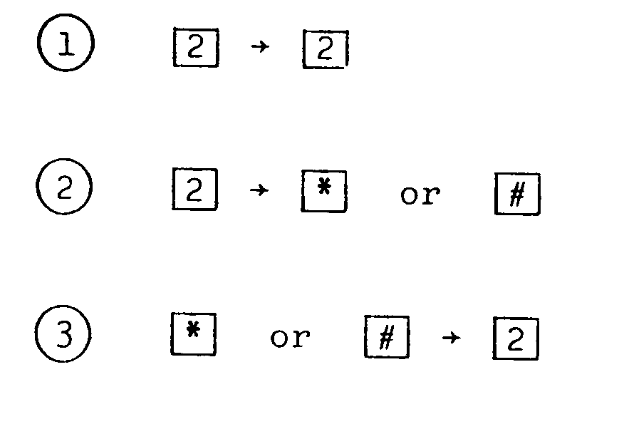
buttons 1a to produce the (E) and (I) marks are designated on the positions numbered "1" and "3" at the top in both side lines of the central line of push-buttons in the above embodiment, it is to be noted that they may be designated at two positions in opposing relationship with each other in both side lines of the central push-button line. - In addition, to prevent the following disadvantage, a push-button may be depressed twice. When it happens that a person gives a voice like the so-called DTMF signals, there may cause the disadvantage that some mode be set in a dictating apparatus without operating a push-button of a telephone.
- In such a case, the push-button may be depressed twice. For example, as in the following button operations in recording, it may be achieved to prevent the disadvantage by depressing the buttons twice.
Claims (10)
- A telephone dictating apparatus into which modes associated with a tape running system can be set in response to DTMF (Dual Tone Multi Frequency) signals from a push-button telephone provided with four push-buttons in each of three longitudinal lines, comprising DTMF signal converting means for converting DTMF signals given by depressing four push-buttons (1a) in one of three longitudinal lines to four mode signals in the same order as that of said four push-buttons,
characterized in that said four push-buttons (1a) comprise a one to one correspondence to four mode setting positions of slide switches (13, 32) for setting modes of a hand microphone (12, 31) for dictation or slide switches (22, 42) for setting modes of a portable dictating apparatus (21, 41), wherein the positions of the telephone push-buttons correspond to the positions of the slide switch belonging to the dictating apparatus. - A telephone dictating apparatus according to Claim 1 in which said DTMF signal converting means converts DTMF signals given by depressing four push-buttons in the central line of said three longitudinal lines to mode signals associated with a tape running system.
- A telephone dictating apparatus according to Claim 2 in which said DTMF signal converting means converts DTMF signals given by depressing two push-buttons (1a) arranged in opposed relationship with each other on both sides of said central line to cue signals for recording different marks ((E), (I)).
- A telephone dictating apparatus according to Claim 3 in which said DTMF signal converting means converts DTMF signals given by depressing two push-buttons (1a) arranged in opposed relationship with each other at the top of both side lines of said central line to cue signals for recording different marks ((E), (I)).
- A telephone dictating apparatus according to Claim 1 or Claim 2 in which said DTMF signal converting means converts DTMF signals given by depressing said four push-buttons (1a) to mode signals for recording, stopping, reproducing and tape rewinding operations.
- A telephone dictating apparatus according to Claim 3 or Claim 4 in which said different marks are an (I) mark corresponding to an instruction and an (E) mark corresponding to a body of dictation.
- A telephone dictating apparatus according to Claim 1 in which the dictating apparatus comprises a DTMF receiver (4) which is the DTMF signal converting means, a main CPU (5), an amplifier (6), a tape deck drive CPU (7), a cassette tape recorder deck (8) and a capacitor (9) for cutting off a DC component.
- A telephone dictating apparatus according to Claim 1 in which the mode setting is effective when push-buttons are depressed twice or more within a given time period.
- A telephone dictating apparatus according to Claim 8 in which a push-button to be depressed later is the same as a push-button depressed first.
- A telephone dictating apparatus according to Claim 8 in which a push-button to be depressed later is different from a push-button depressed first.
Applications Claiming Priority (2)
| Application Number | Priority Date | Filing Date | Title |
|---|---|---|---|
| JP61225213A JP2557050B2 (en) | 1986-09-24 | 1986-09-24 | Dictation device |
| JP225213/86 | 1986-09-24 |
Publications (3)
| Publication Number | Publication Date |
|---|---|
| EP0261680A2 EP0261680A2 (en) | 1988-03-30 |
| EP0261680A3 EP0261680A3 (en) | 1989-06-07 |
| EP0261680B1 true EP0261680B1 (en) | 1993-01-13 |
Family
ID=16825757
Family Applications (1)
| Application Number | Title | Priority Date | Filing Date |
|---|---|---|---|
| EP87113979A Expired - Lifetime EP0261680B1 (en) | 1986-09-24 | 1987-09-24 | Telephon dictating apparatus |
Country Status (4)
| Country | Link |
|---|---|
| US (1) | US4955051A (en) |
| EP (1) | EP0261680B1 (en) |
| JP (1) | JP2557050B2 (en) |
| DE (1) | DE3783547T2 (en) |
Families Citing this family (10)
| Publication number | Priority date | Publication date | Assignee | Title |
|---|---|---|---|---|
| US6002558A (en) * | 1990-09-18 | 1999-12-14 | Rines; Carol Mary | Method of and apparatus for expanding functionality of vehicle cassette tape-player decks to permit dictation or other recording and automatic remote station relaying of the same |
| US5898916A (en) * | 1994-06-30 | 1999-04-27 | Dictaphone Corporation | Cordless telephone for use with dictation system |
| US5598463A (en) * | 1994-10-12 | 1997-01-28 | Saccardo; John | Remote terminal for central dictating system |
| US5828730A (en) | 1995-01-19 | 1998-10-27 | Sten-Tel, Inc. | Method and apparatus for recording and managing communications for transcription |
| DE19528038C2 (en) * | 1995-07-31 | 2002-02-21 | Grundig Ag | Dictaphone with wireless data transmission |
| CA2235572A1 (en) * | 1997-06-18 | 1998-12-18 | Howard B. Rosen | Electronic memo pad for use with touch-tone telephones |
| US5956298A (en) * | 1997-11-10 | 1999-09-21 | Gough; Jesse Lynn | Voice prompting and indexing dictation recorder |
| KR100241790B1 (en) * | 1997-12-31 | 2000-02-01 | 윤종용 | Non-barge-in automatic voice announce unit and method thereof |
| US6888537B2 (en) * | 2002-02-13 | 2005-05-03 | Siemens Technology-To-Business Center, Llc | Configurable industrial input devices that use electrically conductive elastomer |
| CN1889615B (en) * | 2006-07-27 | 2010-09-08 | 赵伟荣 | Hotel check-out controlling system |
Family Cites Families (11)
| Publication number | Priority date | Publication date | Assignee | Title |
|---|---|---|---|---|
| US3647973A (en) * | 1967-12-04 | 1972-03-07 | Peter James | Computer system utilizing a telephone as an input device |
| US4645875A (en) * | 1970-11-12 | 1987-02-24 | Todd Leonard M | Telephone answering programming devices |
| US3725589A (en) * | 1972-02-14 | 1973-04-03 | M Golden | Remote-control system for intelligence-recording apparatus with control tone eliminating switching |
| JPS553577U (en) * | 1978-06-22 | 1980-01-10 | ||
| US4309571A (en) * | 1980-05-05 | 1982-01-05 | Dictaphone Corporation | Telephone-adapter apparatus for a dictation unit |
| JPS5767457U (en) * | 1980-10-09 | 1982-04-22 | ||
| US4488274A (en) * | 1982-03-04 | 1984-12-11 | Lanier Business Products, Inc. | Remote dictation transcription system |
| US4688117A (en) * | 1983-12-21 | 1987-08-18 | Dictaphone Corporation | Display including variable mode for a record and/or playback device |
| US4700376A (en) * | 1984-01-31 | 1987-10-13 | Olympus Optical Co., Ltd. | Automatic telephone answering apparatus with remote control signal muting |
| JPS60250760A (en) * | 1984-05-28 | 1985-12-11 | Tamura Electric Works Ltd | Functional telephone set |
| JPS6170841A (en) * | 1984-09-13 | 1986-04-11 | Hashimoto Corp | Telephone automatic response recording device with ease of operation |
-
1986
- 1986-09-24 JP JP61225213A patent/JP2557050B2/en not_active Expired - Lifetime
-
1987
- 1987-09-22 US US07/099,473 patent/US4955051A/en not_active Expired - Fee Related
- 1987-09-24 EP EP87113979A patent/EP0261680B1/en not_active Expired - Lifetime
- 1987-09-24 DE DE8787113979T patent/DE3783547T2/en not_active Expired - Fee Related
Also Published As
| Publication number | Publication date |
|---|---|
| DE3783547D1 (en) | 1993-02-25 |
| US4955051A (en) | 1990-09-04 |
| JP2557050B2 (en) | 1996-11-27 |
| EP0261680A2 (en) | 1988-03-30 |
| JPS6380664A (en) | 1988-04-11 |
| EP0261680A3 (en) | 1989-06-07 |
| DE3783547T2 (en) | 1993-05-13 |
Similar Documents
| Publication | Publication Date | Title |
|---|---|---|
| CA1326542C (en) | Modular dictation/transcription system | |
| US4860339A (en) | Programmable telephone/dictation terminal and method of operating same | |
| EP0261680B1 (en) | Telephon dictating apparatus | |
| EP0260352A1 (en) | Mobile telephone answering and recording apparatus | |
| US3984644A (en) | Central dictation system with coded constant current levels for transmission of control signals | |
| US4121262A (en) | Magnetic recording/reproducing device | |
| JPH0419671Y2 (en) | ||
| US4933781A (en) | Recording method and a recording and/or reproducing apparatus | |
| CA1279267C (en) | Transcription control over plural interconnected modules | |
| US4788713A (en) | One button control system for telephone answering device | |
| US4975894A (en) | Method and apparatus for controlling dictation on or transcription from recording units in a dictation system | |
| US6314331B1 (en) | Enhanced user control operations for sound recording system | |
| EP0216528B1 (en) | Automatic telephone answering apparatus | |
| JPS627250A (en) | Automatic answering telephone set | |
| GB2158280A (en) | Audio and/or video player | |
| JPS58215851A (en) | Telephone set | |
| JP2563646B2 (en) | Answering machine | |
| JP2760055B2 (en) | Answering machine | |
| JP2762564B2 (en) | Answering machine | |
| CA1048938A (en) | Control current generator for central dictation system | |
| JPS6180642A (en) | tape recorder | |
| GB2179779A (en) | Method and apparatus for controlling dictation on or transcription from recording units in a dictation system | |
| JPS6358419B2 (en) | ||
| JPS6222274A (en) | Central dictating device | |
| JPS6069947A (en) | Message recording device for remote control answering machine |
Legal Events
| Date | Code | Title | Description |
|---|---|---|---|
| PUAI | Public reference made under article 153(3) epc to a published international application that has entered the european phase |
Free format text: ORIGINAL CODE: 0009012 |
|
| AK | Designated contracting states |
Kind code of ref document: A2 Designated state(s): DE FR GB |
|
| PUAL | Search report despatched |
Free format text: ORIGINAL CODE: 0009013 |
|
| AK | Designated contracting states |
Kind code of ref document: A3 Designated state(s): DE FR GB |
|
| 17P | Request for examination filed |
Effective date: 19890811 |
|
| 17Q | First examination report despatched |
Effective date: 19910530 |
|
| GRAA | (expected) grant |
Free format text: ORIGINAL CODE: 0009210 |
|
| AK | Designated contracting states |
Kind code of ref document: B1 Designated state(s): DE FR GB |
|
| REF | Corresponds to: |
Ref document number: 3783547 Country of ref document: DE Date of ref document: 19930225 |
|
| ET | Fr: translation filed | ||
| PLBE | No opposition filed within time limit |
Free format text: ORIGINAL CODE: 0009261 |
|
| STAA | Information on the status of an ep patent application or granted ep patent |
Free format text: STATUS: NO OPPOSITION FILED WITHIN TIME LIMIT |
|
| 26N | No opposition filed | ||
| PGFP | Annual fee paid to national office [announced via postgrant information from national office to epo] |
Ref country code: FR Payment date: 19980909 Year of fee payment: 12 |
|
| PGFP | Annual fee paid to national office [announced via postgrant information from national office to epo] |
Ref country code: GB Payment date: 19981001 Year of fee payment: 12 |
|
| PGFP | Annual fee paid to national office [announced via postgrant information from national office to epo] |
Ref country code: DE Payment date: 19981005 Year of fee payment: 12 |
|
| PG25 | Lapsed in a contracting state [announced via postgrant information from national office to epo] |
Ref country code: GB Free format text: LAPSE BECAUSE OF NON-PAYMENT OF DUE FEES Effective date: 19990924 |
|
| GBPC | Gb: european patent ceased through non-payment of renewal fee |
Effective date: 19990924 |
|
| PG25 | Lapsed in a contracting state [announced via postgrant information from national office to epo] |
Ref country code: FR Free format text: LAPSE BECAUSE OF NON-PAYMENT OF DUE FEES Effective date: 20000531 |
|
| PG25 | Lapsed in a contracting state [announced via postgrant information from national office to epo] |
Ref country code: DE Free format text: LAPSE BECAUSE OF NON-PAYMENT OF DUE FEES Effective date: 20000701 |
|
| REG | Reference to a national code |
Ref country code: FR Ref legal event code: ST |