EP0188271B1 - Error correction encoding system - Google Patents
Error correction encoding system Download PDFInfo
- Publication number
- EP0188271B1 EP0188271B1 EP86100413A EP86100413A EP0188271B1 EP 0188271 B1 EP0188271 B1 EP 0188271B1 EP 86100413 A EP86100413 A EP 86100413A EP 86100413 A EP86100413 A EP 86100413A EP 0188271 B1 EP0188271 B1 EP 0188271B1
- Authority
- EP
- European Patent Office
- Prior art keywords
- data
- error
- side unit
- correcting code
- error correcting
- Prior art date
- Legal status (The legal status is an assumption and is not a legal conclusion. Google has not performed a legal analysis and makes no representation as to the accuracy of the status listed.)
- Expired - Lifetime
Links
- 238000004891 communication Methods 0.000 claims description 26
- 238000000034 method Methods 0.000 claims description 15
- 238000005562 fading Methods 0.000 claims description 9
- 238000001514 detection method Methods 0.000 description 9
- 230000005540 biological transmission Effects 0.000 description 5
- 230000004044 response Effects 0.000 description 5
- 238000010586 diagram Methods 0.000 description 4
- 238000009792 diffusion process Methods 0.000 description 3
- 230000000694 effects Effects 0.000 description 3
- 230000003111 delayed effect Effects 0.000 description 2
- 230000007704 transition Effects 0.000 description 2
- 230000003466 anti-cipated effect Effects 0.000 description 1
- 125000004122 cyclic group Chemical group 0.000 description 1
- 230000001934 delay Effects 0.000 description 1
- 238000002360 preparation method Methods 0.000 description 1
- 230000011664 signaling Effects 0.000 description 1
Images


Classifications
-
- H—ELECTRICITY
- H04—ELECTRIC COMMUNICATION TECHNIQUE
- H04L—TRANSMISSION OF DIGITAL INFORMATION, e.g. TELEGRAPHIC COMMUNICATION
- H04L1/00—Arrangements for detecting or preventing errors in the information received
- H04L1/12—Arrangements for detecting or preventing errors in the information received by using return channel
- H04L1/16—Arrangements for detecting or preventing errors in the information received by using return channel in which the return channel carries supervisory signals, e.g. repetition request signals
- H04L1/18—Automatic repetition systems, e.g. Van Duuren systems
- H04L1/1812—Hybrid protocols; Hybrid automatic repeat request [HARQ]
- H04L1/1819—Hybrid protocols; Hybrid automatic repeat request [HARQ] with retransmission of additional or different redundancy
-
- H—ELECTRICITY
- H03—ELECTRONIC CIRCUITRY
- H03M—CODING; DECODING; CODE CONVERSION IN GENERAL
- H03M13/00—Coding, decoding or code conversion, for error detection or error correction; Coding theory basic assumptions; Coding bounds; Error probability evaluation methods; Channel models; Simulation or testing of codes
- H03M13/03—Error detection or forward error correction by redundancy in data representation, i.e. code words containing more digits than the source words
-
- H—ELECTRICITY
- H04—ELECTRIC COMMUNICATION TECHNIQUE
- H04L—TRANSMISSION OF DIGITAL INFORMATION, e.g. TELEGRAPHIC COMMUNICATION
- H04L1/00—Arrangements for detecting or preventing errors in the information received
- H04L1/0001—Systems modifying transmission characteristics according to link quality, e.g. power backoff
- H04L1/0009—Systems modifying transmission characteristics according to link quality, e.g. power backoff by adapting the channel coding
-
- H—ELECTRICITY
- H04—ELECTRIC COMMUNICATION TECHNIQUE
- H04L—TRANSMISSION OF DIGITAL INFORMATION, e.g. TELEGRAPHIC COMMUNICATION
- H04L1/00—Arrangements for detecting or preventing errors in the information received
- H04L1/0001—Systems modifying transmission characteristics according to link quality, e.g. power backoff
- H04L1/0015—Systems modifying transmission characteristics according to link quality, e.g. power backoff characterised by the adaptation strategy
-
- H—ELECTRICITY
- H04—ELECTRIC COMMUNICATION TECHNIQUE
- H04L—TRANSMISSION OF DIGITAL INFORMATION, e.g. TELEGRAPHIC COMMUNICATION
- H04L1/00—Arrangements for detecting or preventing errors in the information received
- H04L1/0001—Systems modifying transmission characteristics according to link quality, e.g. power backoff
- H04L1/0023—Systems modifying transmission characteristics according to link quality, e.g. power backoff characterised by the signalling
- H04L1/0025—Transmission of mode-switching indication
-
- H—ELECTRICITY
- H04—ELECTRIC COMMUNICATION TECHNIQUE
- H04L—TRANSMISSION OF DIGITAL INFORMATION, e.g. TELEGRAPHIC COMMUNICATION
- H04L1/00—Arrangements for detecting or preventing errors in the information received
- H04L1/004—Arrangements for detecting or preventing errors in the information received by using forward error control
- H04L1/0072—Error control for data other than payload data, e.g. control data
- H04L1/0073—Special arrangements for feedback channel
Definitions
- the present invention relates to an error correction encoding method for use in effecting data communication via a fading channel dominated by burst errors between a transmitting side unit and a receiving side unit as well as to data communication apparatus for use in effecting data communication according to the introductory parts of claims 1 and 2, respectively.
- Error correcting code to automatically correct digital information is indispensable nowadays to improve reliability of computers and data communication systems.
- Two types of error encoding systems are known for the error correcting codes.
- One is suited to random error correction, and the other to burst error correction depending on error patterns to be corrected.
- the burst error is dominant.
- an interleaving system is known as described in "Error Correction Coding Starting to Be Extensively Put into Practice in Various Fields" by Tanaka, Nikkei Electronics, 1975, 12 to 15, PP 48 to 52.
- Both systems are greatly varied in the burst length because in a mobile radio great changes of a vehicle speed ranging from zero to one hundred and several tens of kilometers per hour as well as of a signal reception level ranging from about minus 100 dB to minus several tens of dB occur. Accordingly, several hundred hits of interleave are needed to randomize a signal with use thereof, whereby more delay time is required. Thus, larger capacity memory of a RAM is needed and further throughput efficiency is deteriorated. In addition, to securely effect communication only with an error correcting code having a burst length of several bits, throughput efficiency is sharply deteriorated.
- an error detection system with automatic repeat request is known. Upon detection of an error at the receive terminal, a request for repeat is sent to the transmit terminal via a return channel. Upon receipt of a repeat request in this instance, at least two data blocks are repeated.
- an error involved in the received data is detected as a frame error rate in a block or a bit error rate in the block and an error correcting code is selected in response to the extent of the error rate for encoding and decoding the transmission data.
- An error correction encoding method for use in effecting data communication via a fading channel dominated by burst errors between a transmitting side unit and a receiving side unit is described in claim 1.
- a data communication apparatus according to the invention is described in claim 2.
- the first embodiment of the error correction encoding system detects error frames contained in data received by a receiving side, selects an error correcting code corresponding to a number of error frames contained in block data, and signalling it to a transmitting side, while on the transmitting side, encodes the data with use of the selected error correcting code and transmits it.
- Designated at 1 is a transmitting terminal unit
- 2 is an encoder
- 3 is a transmitter
- 4 is a channel
- 5 is a receiver
- 6 is a decoder
- 8 is a receiving terminal unit
- 9 is an error frame number counter circuit
- 10A is an error correcting code selector
- 11A is an error correcting code memory unit
- 12 is an encoder
- 13 is a transmitter
- 14 is a channel
- 15 is a receiver
- 16 is a decoder
- 11B is an error correcting code memory unit.
- E1, E2, E3 and E4 Four kinds of error correcting codes used in the encoder 2 are known as E1, E2, E3 and E4, and E1 is used in initial setting for encoding (Fig. 2, box 201).
- the encoder 2 gives a number to each frame with use of the correcting code E1, and encodes it.
- the encoder puts together a plurality of the frames into a block to provide encoded data (Fig. 2, box 202).
- the encoded data is modulated in the transmitter 3 and delivered to the channel 4 (Fig. 2, box 301).
- the channel 4 is subjected to fading, and produces burst errors in the modulated signal as a vehicle runs, which is received by the receiving side.
- the receiving side demodulates the received encoded data in the receiver 5 (Fig. 2, box 501).
- the decoder 6 decodes an output from the receiver 5 for each frame corresponding to the error correcting code E1 used in the encoder 2, while error frames are detected by means of an error detecting method based on a cyclic code (Fig. 2, box 601).
- the decoded data is supplied to the receiving terminal unit 8, while the error frame number counter circuit 9 evaluates a rate of an error frame number to all frames contained in a transmitted data block.
- the error correcting code memory unit 11A stores therein numbers corresponding to the error correcting codes E1 to E4.
- the error correcting code selector 10A selects a number indicative of a type of the error correcting code from the error correcting code memory unit 11A corresponding to the error rate of the frames contained in the one block data just received.
- the type number of the error correcting code selected by the error correcting code selector 10A and the number of the error frame are encoded through the encoder 12 and transferred to the transmitter 13 (Fig. 2, box 1201).
- the encoder 12 encodes the data transferred in conformity with the predetermined encoding system.
- the signal modulated by the transmitter 13 is delivered to the transmitting side via the channel 14 (Fig. 2, box 1301).
- the receiver 15, on the receiving side demodulates the received modulated data, and delivers it to the decoder 16 (Fig. 2, box 1501).
- the decoder 16 decodes the type number of the error correcting code and the number of the error frame of the error correcting code supplied from the receiving side (Fig. 2, box 1601).
- the decoder 16 When the decoder 16 detects any error, it requests the receiving side to again transmit the same data to the transmitting side. But, the description is omitted here.
- the decoder 16 takes out the error correcting code from the error correcting code memory unit 11B based on the type number of the received correcting code, and transfers it to the encoder 2 (Fig. 2, box 1602).
- the encoder 2 again transmits the frame data including the frame number received in error to the receiving side via the transmitter 3 with use of the selected error correcting code. Provided that a plurality of the error frames are detected, all the frames are likewise transmitted to the receiving side (Fig. 2, boxes 203, 204, 302).
- the next data from the transmitting terminal unit 1 is transmitted to the receiving side in the same procedure with use of the error correcting code selected by the error correcting code memory unit 11B.
- the error correcting code which the encoder 2 on the transmitting side uses is selected in response to the error rate of the frames within the received data block on the receiving side, and encoded for communication, whereby an encoding system for error correction adapted to communication conditions of the fading channel is provided.
- Fig. 3 illustrates transitions among the error correcting codes E1 to E4.
- the error correcting code E1 is one taking nk bits (n a positive integer) as one block when the bit number possessed by one frame is made k bits (e.g., 1024 bits), having no error correcting bit but only a parity check bit for error detection.
- the error correcting code E2 takes k bits as one block when a bit number possessed by one frame is made k bits, having no bit for error correction but only a parity check bit.
- the error correcting code E3 takes k bits as one block similarly as before, and has an error correcting code with an information rate of 1/2.
- the error correcting code E4 takes k bits as one block and has an error correcting code and a parity check bit. The code further securely transmits data even if an encoding rate is deteriorated to a fraction of several parts by making use of a decoding technique with decision by majority.
- the error correcting codes E1 to E4 are previously stored in the error correcting code memory unit 11B, and selected in response to conditions of a concerning circuit. Namely, when an error produced on the channel 4 has been corrected by making use of the error correcting code E2, provided that conditions of the channel 4 and the speed of an automobile, etc., are kept substantially constant, the error correcting code E2 is not changed, and communication runs with use of the code.
- the state changes to a state with the error correcting code E1 based on information from the receiving side.
- the encoder 2 shown in Fig. 1 is one with use of a diffusion code, and comprises a circuit shown in Fig. 4. It is known that the encoder has in general shift registers and exclusive ORs (mode 2). The circuit of the encoder 2 is uniquely defined as given a generator polynomial. Therefore, with the above diffusion code, the encoder 2 is constructed as shown in Fig. 4. Designated at 30 is an encoding part input terminal, 31 is a b+1 stage shift register, 33 and 35 are b stage shift register, respectively, 32, 34, and 36 are exclusive ORs, respectively, 37 is an information/check changeover switch, and 38 is an encoding part output terminal.
- An information bit supplied to the encoding part input terminal 30 is provided to the information/check changeover switch, while provided to an input of the b+1 stage shift register 31. Thereafter, the information bits are delayed through the respective exclusive ORs and b stage shift registers, and finally a check bit is delivered from an output of the exclusive-OR 36. These information and check bits are alternately sent to the encoding part output terminal 38 with the aid of the information/check changeover switch 37, and transmitted to the transmitter 3.
- the decoder 6 shown in Fig. 1 comprises a circuit shown in Fig. 5.
- the decoder 6 of Fig. 5 is one with use of a diffusion code, and effects majority logic decoding of a convolutional code.
- designated at 42 and 43 are a b stage shift register, respectively, 44 a b+1 stage shift register, and 45 to 49 an exclusive OR, respectively.
- An information bit is supplied to the b stage shift register 42 via the information/check changeover switch 41 serving to alternately switch the information bit and the check bit, and delayed via the b stage shift register 43 and the b+1 stage shift register 44.
- a check bit yielded on the basis of an information bit received from the output of the exclusive OR 46 is delivered.
- the check bit and a check bit supplied via the information check changeover switch 41 are exclusive OR'ed by the exclusive OR circuit 45.
- An output of the exclusive OR 45 is supplied to the exclusive OR 51 on one side, and error detection is effected by the exclusive ORs 51, 54, 55, 57, and 59, a single-stage shift register 52, the b stage shift registers 53, 56, the b+1 stage shift register 58, and a majority element 60.
- an error detector signal for the information bit is available from an output of the majority element 60, while an error detection signal for the check bit available from the output of the exclusive OR 59.
- the output from the majority element 60 is supplied to the exclusive OR 49, whereby an erroneous information bit supplied from the b+1 stage shift register 44 is corrected, and a data output signal is delivered to the receiving terminal unit 8 via the data output terminal 50 of the decoder, while the above output from the majority element 60 is supplied to the information/check changeover switch 61. Further, the output from the exclusive OR 59 is delivered to the information/check switch 61. The information/check changeover switch 61 alternately switches between the error detection signal for the information bit and the error detection signal for the check bit, and delivers them. As a result of it, the error detection signal is supplied to an error frame number counter circuit 9 via an error detection signal output terminal 62.
- the embodiment detects on the receiving side a number of error frames contained in a received data block of data transmitted from the transmitting side, and selects an error correcting code based on a frame error rate.
- the present embodiment is of the same as the first embodiment described before with the exception of a fact that it has not the error correcting code selector and the error correcting code memory unit on the receiving side but having the former only on the transmitting side.
- Fig. 6 designated at 10B is the error correcting code selector, 17 is a unit for preparing data from an error frame number.
- Transmission data transmitted from the transmitting terminal unit 1 is encoded for each frame unit by the encoder 2 with use of the error correcting code E1 in the same way as in Fig. 1, and numbers are assigned to every frames.
- a plurality of the frames are brought together into a block, modulated through the transmitter 3, and delivered to the channel 4.
- the receiving side demodulates the received encoded data by making use of the receiver 5, and thereafter the data is decoded by the decoder 6.
- the decoder 6 decodes the data for every frames as in Fig.
- the error frame number data is encoded in the encoder 12 using a predetermined encoding system, modulated through the transmitter 13, and delivered to the transmitting side.
- the transmitting side receives the transmitted data, demodulates through the receiver 15, and decodes by the decoder 16.
- the error correcting code selector 10B estimates a ratio of an error frame number to a number of all frames within one data block transmitted previously, selects the next error correcting code from the E1 to E4 stored in the error correcting code memory unit 11B corresponding to the error frame rate, and provides it to the encoder 2.
- All the error frames are encoded with use of a newly selected error correcting code, modulated in the transmitter 3, and retransmitted to the receiving side also together with a type of the newly selected error correcting code.
- the next block data is also encoded with the newly selected error correcting code, the error correcting code is changed thereafter corresponding to error frames for every block .
- the error correcting codes E1 to E4 for use in the present embodiment are the same as those described in Fig. 3.
- the present embodiment also effects the error correcting encoding adapted to communication conditions of a fading channel.
- Terminal unit is connected with encoder and decoder.
- Transmitter has the switch between encoder with error correcting code memory unit and encoder with error correcting code selector.
- Receiver has the switch between decoder with error correcting code memory unit and decoder with error frame numbers counter unit.
- the present invention estimates a bit error rate of the whole of one block data received on the receiving side, and selects an error correcting code in response to the estimated bit error rate, while it compares the bit error rate with a channel error rate being specified transmission quality, for thereby deciding the received block data to be proper block data provided that a bit error rate of the received block data is less than the specified channel error rate, while it decides it to be improper if it is more than the specified channel error rate, and as a result of it,it encodes the resulting data with use of the selected error correcting code for retransmission.
- the receiving side estimates the bit error rate of the whole of the one block data with use of the output from the burst length measuring part 7B of Fig. 7, compares the bit error rate with a specified channel error rate, and if improper, requests the transmitting side to retransmit the block data.
- the error correction encoding system transmits the bit error rate estimated thereby, and selects an optimum error correcting code from the error correcting code memory unit based on the bit error rate, and,furthermore,encodes error block data as well as the succeeding data with use of the selected error correcting code and transmits them. Thereafter, the error correcting code is altered corresponding to bit error rates for every blocks.
- K s /N s 1
- K m /N m 0.5
- N m is indicative of an information bit number
- K m is a control bit number, and both are assumed to be 100 and 50 in order.
- a result estimated according to equation (1) i.e., a case according to the embodiment of the present invention are depicted by a solid line A in Fig. 7, while a result evaluated when only a single error correcting code is applied with retransmission depicted by a broken line B in Fig. 7. It is evidenced from the figure that the present invention sharply improves the throughput efficiency.
- the present invention assures an extremely effective error correcting technique upon effecting data communication with use of channels located in strongly varying communication environments. It is anticipated that the throughput efficiency is improved because an optimum error correcting code is selected in conformity with conditions of a communication channel.
Landscapes
- Engineering & Computer Science (AREA)
- Computer Networks & Wireless Communication (AREA)
- Signal Processing (AREA)
- Quality & Reliability (AREA)
- Physics & Mathematics (AREA)
- Probability & Statistics with Applications (AREA)
- Theoretical Computer Science (AREA)
- Detection And Prevention Of Errors In Transmission (AREA)
Description
- The present invention relates to an error correction encoding method for use in effecting data communication via a fading channel dominated by burst errors between a transmitting side unit and a receiving side unit as well as to data communication apparatus for use in effecting data communication according to the introductory parts of
claims - "Error correcting code" to automatically correct digital information is indispensable nowadays to improve reliability of computers and data communication systems. Two types of error encoding systems are known for the error correcting codes. One is suited to random error correction, and the other to burst error correction depending on error patterns to be corrected. In particular, in extremely bad-conditioned channels such for example as fading channels in communication among vehicles such as automobiles, the burst error is dominant. For a system to correct the burst error, an interleaving system is known as described in "Error Correction Coding Starting to Be Extensively Put into Practice in Various Fields" by Tanaka, Nikkei Electronics, 1975, 12 to 15,
PP 48 to 52. This interleaves the burst error, and thereby converts it to a random error which can be then satisfactorily processed with use of proper random error correcting codes. However, the system can not be applied to systems requiring a severe delay time characteristic since the sytem delays in its decoding. - In addition, another error correction system such an automatic repeat request method as being described in Malcolm C. Easton "Bath Throughput Efficiency of ADCCP/HDLC/SDLC Selective Reject Protcols" 1980, IEEE, PP 187 to 195 is known.
- Both systems are greatly varied in the burst length because in a mobile radio great changes of a vehicle speed ranging from zero to one hundred and several tens of kilometers per hour as well as of a signal reception level ranging from about minus 100 dB to minus several tens of dB occur. Accordingly, several hundred hits of interleave are needed to randomize a signal with use thereof, whereby more delay time is required. Thus, larger capacity memory of a RAM is needed and further throughput efficiency is deteriorated. In addition, to securely effect communication only with an error correcting code having a burst length of several bits, throughput efficiency is sharply deteriorated.
- From US-A-3078443 is known a technique to encode the input information data with use of encoding codes different in redundancies and to adaptively alter those encoding codes in response to the error rate of decoded data. This system provides, however, no back-transmission of the information data about error frames.
- From an article in Electronics, Dec. 27, 1965, pages 70 to 79, an error detection system with automatic repeat request is known. Upon detection of an error at the receive terminal, a request for repeat is sent to the transmit terminal via a return channel. Upon receipt of a repeat request in this instance, at least two data blocks are repeated.
- It is an object of the present invention to provide an excellent error correction encoding system capable of data communication with less deteriorated throughput efficiency even if a vehicle changes in its speed from zero to one hundred and several tens of km/h as well as in a signal reception level from a lower one to several tens of dB.
- According to the present invention, in receiving any data sent from a transmitting side to a receiving side, an error involved in the received data is detected as a frame error rate in a block or a bit error rate in the block and an error correcting code is selected in response to the extent of the error rate for encoding and decoding the transmission data.
- An error correction encoding method according to the invention for use in effecting data communication via a fading channel dominated by burst errors between a transmitting side unit and a receiving side unit is described in
claim 1. - A data communication apparatus according to the invention is described in
claim 2. - Fig. 1 is a block diagram illustrating a first embodiment of an error correction encoding system according to the present invention,
- Fig. 2 is a flowchart illustrating operation of the error correction encoding system of Fig. 1,
- Fig. 3 is a schematic showing transitions among respective steps of from E1 to E4 of error correcting codes,
- Fig. 4 is a block diagram of an
encoder 2 shown in Fig. 1, - Fig. 5 is a block diagram of a
decoder 6 of Fig. 1, - Fig. 6 is a block diagram illustrating a second embodiment of the error correction encoding system according to the present invention, and
- Fig. 7 is a schematic illustrating throughput efficiency in the embodiments of the error correction encoding system according to the present invention.
- As shown in Fig. 1, the first embodiment of the error correction encoding system according to the present invention detects error frames contained in data received by a receiving side, selects an error correcting code corresponding to a number of error frames contained in block data, and signalling it to a transmitting side, while on the transmitting side, encodes the data with use of the selected error correcting code and transmits it.
- Designated at 1 is a transmitting terminal unit, 2 is an encoder, 3 is a transmitter, 4 is a channel, 5 is a receiver, 6 is a decoder, 8 is a receiving terminal unit, 9 is an error frame number counter circuit, 10A is an error correcting code selector, 11A is an error correcting code memory unit, 12 is an encoder, 13 is a transmitter, 14 is a channel, 15 is a receiver, 16 is a decoder, and 11B is an error correcting code memory unit. Referring to Fig. 2, operation of the error correction encoding system of Fig. 1 will be described below. Transmission data is delivered from the transmitting
terminal unit 1 to theencoder 2. Four kinds of error correcting codes used in theencoder 2 are known as E1, E2, E3 and E4, and E1 is used in initial setting for encoding (Fig. 2, box 201). Theencoder 2 gives a number to each frame with use of the correcting code E1, and encodes it. The encoder puts together a plurality of the frames into a block to provide encoded data (Fig. 2, box 202). The encoded data is modulated in thetransmitter 3 and delivered to the channel 4 (Fig. 2, box 301). Thechannel 4 is subjected to fading, and produces burst errors in the modulated signal as a vehicle runs, which is received by the receiving side. The receiving side demodulates the received encoded data in the receiver 5 (Fig. 2, box 501). In succession, thedecoder 6 decodes an output from thereceiver 5 for each frame corresponding to the error correcting code E1 used in theencoder 2, while error frames are detected by means of an error detecting method based on a cyclic code (Fig. 2, box 601). The decoded data is supplied to thereceiving terminal unit 8, while the error framenumber counter circuit 9 evaluates a rate of an error frame number to all frames contained in a transmitted data block. The error correctingcode memory unit 11A stores therein numbers corresponding to the error correcting codes E1 to E4. The errorcorrecting code selector 10A selects a number indicative of a type of the error correcting code from the error correctingcode memory unit 11A corresponding to the error rate of the frames contained in the one block data just received. The type number of the error correcting code selected by the errorcorrecting code selector 10A and the number of the error frame are encoded through theencoder 12 and transferred to the transmitter 13 (Fig. 2, box 1201). Theencoder 12 encodes the data transferred in conformity with the predetermined encoding system. The signal modulated by thetransmitter 13 is delivered to the transmitting side via the channel 14 (Fig. 2, box 1301). Thereceiver 15, on the receiving side, demodulates the received modulated data, and delivers it to the decoder 16 (Fig. 2, box 1501). Thedecoder 16 decodes the type number of the error correcting code and the number of the error frame of the error correcting code supplied from the receiving side (Fig. 2, box 1601). When thedecoder 16 detects any error, it requests the receiving side to again transmit the same data to the transmitting side. But, the description is omitted here. In addition, thedecoder 16 takes out the error correcting code from the error correctingcode memory unit 11B based on the type number of the received correcting code, and transfers it to the encoder 2 (Fig. 2, box 1602). Theencoder 2 again transmits the frame data including the frame number received in error to the receiving side via thetransmitter 3 with use of the selected error correcting code. Provided that a plurality of the error frames are detected, all the frames are likewise transmitted to the receiving side (Fig. 2,boxes terminal unit 1 is transmitted to the receiving side in the same procedure with use of the error correcting code selected by the error correctingcode memory unit 11B. With the present embodiment of the encoding system for error correction, the error correcting code which theencoder 2 on the transmitting side uses is selected in response to the error rate of the frames within the received data block on the receiving side, and encoded for communication, whereby an encoding system for error correction adapted to communication conditions of the fading channel is provided. - Fig. 3 illustrates transitions among the error correcting codes E1 to E4. The error correcting code E1 is one taking nk bits (n a positive integer) as one block when the bit number possessed by one frame is made k bits (e.g., 1024 bits), having no error correcting bit but only a parity check bit for error detection. The error correcting code E2 takes k bits as one block when a bit number possessed by one frame is made k bits, having no bit for error correction but only a parity check bit. The error correcting code E3 takes k bits as one block similarly as before, and has an error correcting code with an information rate of 1/2. The error correcting code E4 takes k bits as one block and has an error correcting code and a parity check bit. The code further securely transmits data even if an encoding rate is deteriorated to a fraction of several parts by making use of a decoding technique with decision by majority.
- The error correcting codes E1 to E4 are previously stored in the error correcting
code memory unit 11B, and selected in response to conditions of a concerning circuit. Namely, when an error produced on thechannel 4 has been corrected by making use of the error correcting code E2, provided that conditions of thechannel 4 and the speed of an automobile, etc., are kept substantially constant, the error correcting code E2 is not changed, and communication runs with use of the code. - With the conditions of the
channel 4 bad-conditioned, error bits are increased, and the state of the encoding system for error correction changes to a state with the error correcting code E3 based on information available from the receiving side. - Contrary, with the
channel 4 better-conditioned, the state changes to a state with the error correcting code E1 based on information from the receiving side. - The
encoder 2 shown in Fig. 1 is one with use of a diffusion code, and comprises a circuit shown in Fig. 4. It is known that the encoder has in general shift registers and exclusive ORs (mode 2). The circuit of theencoder 2 is uniquely defined as given a generator polynomial. Therefore, with the above diffusion code, theencoder 2 is constructed as shown in Fig. 4. Designated at 30 is an encoding part input terminal, 31 is a b+1 stage shift register, 33 and 35 are b stage shift register, respectively, 32, 34, and 36 are exclusive ORs, respectively, 37 is an information/check changeover switch, and 38 is an encoding part output terminal. An information bit supplied to the encodingpart input terminal 30 is provided to the information/check changeover switch, while provided to an input of the b+1stage shift register 31. Thereafter, the information bits are delayed through the respective exclusive ORs and b stage shift registers, and finally a check bit is delivered from an output of the exclusive-OR 36. These information and check bits are alternately sent to the encodingpart output terminal 38 with the aid of the information/check changeover switch 37, and transmitted to thetransmitter 3. - In addition, the
decoder 6 shown in Fig. 1 comprises a circuit shown in Fig. 5. Thedecoder 6 of Fig. 5 is one with use of a diffusion code, and effects majority logic decoding of a convolutional code. In Fig. 5, designated at 42 and 43 are a b stage shift register, respectively, 44 a b+1 stage shift register, and 45 to 49 an exclusive OR, respectively. An information bit is supplied to the bstage shift register 42 via the information/check changeover switch 41 serving to alternately switch the information bit and the check bit, and delayed via the bstage shift register 43 and the b+1stage shift register 44. In addition, a check bit yielded on the basis of an information bit received from the output of the exclusive OR 46 is delivered. - The check bit and a check bit supplied via the information
check changeover switch 41 are exclusive OR'ed by the exclusive ORcircuit 45. An output of the exclusive OR 45 is supplied to the exclusive OR 51 on one side, and error detection is effected by theexclusive ORs stage shift register 52, the b stage shift registers 53, 56, the b+1stage shift register 58, and amajority element 60. As a result of it, an error detector signal for the information bit is available from an output of themajority element 60, while an error detection signal for the check bit available from the output of the exclusive OR 59. The output from themajority element 60 is supplied to the exclusive OR 49, whereby an erroneous information bit supplied from the b+1stage shift register 44 is corrected, and a data output signal is delivered to the receivingterminal unit 8 via thedata output terminal 50 of the decoder, while the above output from themajority element 60 is supplied to the information/check changeover switch 61. Further, the output from the exclusive OR 59 is delivered to the information/check switch 61. The information/check changeover switch 61 alternately switches between the error detection signal for the information bit and the error detection signal for the check bit, and delivers them. As a result of it, the error detection signal is supplied to an error framenumber counter circuit 9 via an error detection signal output terminal 62. - A second embodiment of the error correction encoding system according to the present invention will be described with reference to Fig. 6.
- The embodiment detects on the receiving side a number of error frames contained in a received data block of data transmitted from the transmitting side, and selects an error correcting code based on a frame error rate. The present embodiment is of the same as the first embodiment described before with the exception of a fact that it has not the error correcting code selector and the error correcting code memory unit on the receiving side but having the former only on the transmitting side.
- In Fig. 6, designated at 10B is the error correcting code selector, 17 is a unit for preparing data from an error frame number. Other symbols in the same figure are the same as those shown in Fig. 1. Transmission data transmitted from the transmitting
terminal unit 1 is encoded for each frame unit by theencoder 2 with use of the error correcting code E1 in the same way as in Fig. 1, and numbers are assigned to every frames. In addition, a plurality of the frames are brought together into a block, modulated through thetransmitter 3, and delivered to thechannel 4. The receiving side demodulates the received encoded data by making use of thereceiver 5, and thereafter the data is decoded by thedecoder 6. Thedecoder 6 decodes the data for every frames as in Fig. 1, detects an erroneous frame, and prepares data from an error frame number in thedata preparation unit 17. Then, the error frame number data is encoded in theencoder 12 using a predetermined encoding system, modulated through thetransmitter 13, and delivered to the transmitting side. The transmitting side receives the transmitted data, demodulates through thereceiver 15, and decodes by thedecoder 16. In succession, the error correctingcode selector 10B estimates a ratio of an error frame number to a number of all frames within one data block transmitted previously, selects the next error correcting code from the E1 to E4 stored in the error correctingcode memory unit 11B corresponding to the error frame rate, and provides it to theencoder 2. All the error frames are encoded with use of a newly selected error correcting code, modulated in thetransmitter 3, and retransmitted to the receiving side also together with a type of the newly selected error correcting code. Although the next block data is also encoded with the newly selected error correcting code, the error correcting code is changed thereafter corresponding to error frames for every block . Moreover, the error correcting codes E1 to E4 for use in the present embodiment are the same as those described in Fig. 3. As described above, the present embodiment also effects the error correcting encoding adapted to communication conditions of a fading channel. - Although the above two embodiments are described with a half duplex method. This error correcting method can be adapted to full duplex method. This full duplex method can be realized by having the functioning circuits between the transmitting equipment and receiving equipment as shown in Fig. 1. Scheme of the full duplex equipment is as follows: Terminal unit is connected with encoder and decoder. Transmitter has the switch between encoder with error correcting code memory unit and encoder with error correcting code selector. Receiver has the switch between decoder with error correcting code memory unit and decoder with error frame numbers counter unit.
- Then a third embodiment of the present invention will be described.
- The present invention estimates a bit error rate of the whole of one block data received on the receiving side, and selects an error correcting code in response to the estimated bit error rate, while it compares the bit error rate with a channel error rate being specified transmission quality, for thereby deciding the received block data to be proper block data provided that a bit error rate of the received block data is less than the specified channel error rate, while it decides it to be improper if it is more than the specified channel error rate, and as a result of it,it encodes the resulting data with use of the selected error correcting code for retransmission.
- Namely, the receiving side estimates the bit error rate of the whole of the one block data with use of the output from the burst length measuring part 7B of Fig. 7, compares the bit error rate with a specified channel error rate, and if improper, requests the transmitting side to retransmit the block data. Simultaneously, the error correction encoding system transmits the bit error rate estimated thereby, and selects an optimum error correcting code from the error correcting code memory unit based on the bit error rate, and,furthermore,encodes error block data as well as the succeeding data with use of the selected error correcting code and transmits them. Thereafter, the error correcting code is altered corresponding to bit error rates for every blocks.
- Referring to Fig. 7, a throughput efficiency with respect to the bit error rate will be described. Automobile telephones and pocketable telephones relatively often communicate in their stopping. For brevity, such situation of the channel 412 is assumed that the automobile is at a stop and is running at a speed from 20 to 100 km/h.
- It is further assumed that the time interval taken by the automobile in communication at a stop is ts, and that in running tm, and a ratio therebetween with respect to the whole transmission time is 7 to 3. Communication error rates at a stop and in running of the automobile are respectively assumed Ps and Pm. According to experimental data, Ps = 0 and Pm = 10⁻³.
Under the conditions, the throughout efficiency can be approximated by (1).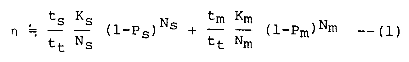
Here, it is a total of the communication time and is equal to the sum of ts and tm. Ks/Ns and Km/Nm are respectively encoding rates of error correction. Since no error is produced at automobile stoppage, Ks/Ns=1, while since in its running error correction is manifested, Km/Nm=0.5. Nm is indicative of an information bit number and Km is a control bit number, and both are assumed to be 100 and 50 in order. A result estimated according to equation (1), i.e., a case according to the embodiment of the present invention are depicted by a solid line A in Fig. 7, while a result evaluated when only a single error correcting code is applied with retransmission depicted by a broken line B in Fig. 7. It is evidenced from the figure that the present invention sharply improves the throughput efficiency. - Although in vehicle communication radio channels are subjected to change of environment at all times due to the influence of fading, as described above, the present invention assures an extremely effective error correcting technique upon effecting data communication with use of channels located in strongly varying communication environments. It is anticipated that the throughput efficiency is improved because an optimum error correcting code is selected in conformity with conditions of a communication channel.
Claims (2)
- An error correction encoding method for use in effecting data communication via a fading channel dominated by burst errors between a transmitting side unit and a receiving side unit, said method supervising an error rate of received data, adaptively changing an error correcting code and comprising the steps of
inputting information data in the transmitting side unit, encoding said input information data with codes of different types with different redundancies and selecting one type of error correcting code according to the initial state or the error rate of decoded data,
transmitting said encoded data to said receiving side unit, receiving data transmitted from said transmitting side unit in the receiving side unit,
decoding said transmitted data using said error correcting code of said selected number,
evaluating the error rate of said decoded data and
changing the error correcting code according to said error rate,
characterised in that
the method further comprises the steps of
providing in the transmitting side unit the encoded data to be transmitted to the receiving side unit by giving a number to each data frame and putting together a plurality of data frames of the input information data into a data block to provide encoded data,
decoding said transmitted data in the receiving side unit for each frame and detecting an erroneous or error frame and the number of the error frame,
encoding the number of the error frame,
transmitting said error frame number data to said transmitting side unit,
receiving data transmitted from said receiving side unit in the transmitting side unit,
decoding said received data using said error correcting code of said selected number,
evaluating as the error rate of said decoded data the ratio of error frames to all data frames within one data block either on the receiving or on the transmitting side and selecting a number indicative of the type of the error correcting code according to said ratio of error frames. - A data communication apparatus for use in effecting data communication via a fading channel dominated by burst errors comprising a transmitting side unit, a receiving side unit and said communication channel between,
said transmitting side unit comprising:
a source (1) of input information data,
a means (2) for encoding said input information data with error correcting codes of different types with different redundancies and for selecting one type of error correcting code according to the initial state or the error rate of decoded data,
a transmitter (3) for transmitting said encoded data to said receiving side unit, and
said receiving side unit comprising:
a receiver (5) for receiving data transmitted from said transmitting side unit, and
a means (6, 7) for decoding the output from said receiver (5) using said error correcting code of said selected number,
the data communication apparatus further comprising:
a means for evaluating the error rate of said decoded data, and
a means for changing the error correcting code according to said error rate,
characterised in that
the communication apparatus has half duplex and/or full duplex function,
the means for encoding on the transmitting side comprises one encoder (2) which gives a number to each data frame and puts together a plurality of data frames of the input information data into a data block to provide encoded data,
the means for decoding on the receiving side comprises one decoder (6) which decodes the output from said receiver (5) for each frame and detects an erroneous or error frame and the number of the error frame,
the receiving side unit comprises:
an encoder (12) for encoding the number of the error frame and
a transmitter (13) for transmitting said error frame number data to said transmitting side unit,
the transmitting side unit comprises:
a receiver (15) for receiving data transmitted from said receiving side unit, and
a decoder (16) for decoding an output from said receiver (15) using said error correcting code for said selected number, and
that the means (9, 10 B) for evaluating the error rate of the decoded data evaluates the ratio of error frames to all data frames within one data block, and
said means for changing the error correction code comprises an error correcting code selector (10 A, 10 B) for selecting a number indicative of the type of the error correcting code according to said ratio of error frames.
Applications Claiming Priority (4)
| Application Number | Priority Date | Filing Date | Title |
|---|---|---|---|
| JP60003381A JPH0697748B2 (en) | 1985-01-14 | 1985-01-14 | Error correction coding method |
| JP3381/85 | 1985-01-14 | ||
| JP500985A JPS61164352A (en) | 1985-01-17 | 1985-01-17 | Burst error detection method |
| JP5009/85 | 1985-01-17 |
Publications (3)
| Publication Number | Publication Date |
|---|---|
| EP0188271A2 EP0188271A2 (en) | 1986-07-23 |
| EP0188271A3 EP0188271A3 (en) | 1989-05-24 |
| EP0188271B1 true EP0188271B1 (en) | 1992-07-15 |
Family
ID=26336954
Family Applications (1)
| Application Number | Title | Priority Date | Filing Date |
|---|---|---|---|
| EP86100413A Expired - Lifetime EP0188271B1 (en) | 1985-01-14 | 1986-01-14 | Error correction encoding system |
Country Status (4)
| Country | Link |
|---|---|
| US (1) | US4701923A (en) |
| EP (1) | EP0188271B1 (en) |
| CA (1) | CA1235189A (en) |
| DE (1) | DE3685962T2 (en) |
Families Citing this family (102)
| Publication number | Priority date | Publication date | Assignee | Title |
|---|---|---|---|---|
| GB2196516A (en) * | 1987-03-10 | 1988-04-27 | British Broadcasting Corp | Data transmission |
| JP2881773B2 (en) * | 1988-07-30 | 1999-04-12 | ソニー株式会社 | Error correction device |
| US7606575B2 (en) * | 1988-08-04 | 2009-10-20 | Broadcom Corporation | Remote radio data communication system with data rate switching |
| US20010050943A1 (en) * | 1989-08-03 | 2001-12-13 | Mahany Ronald L. | Radio frequency communication network having adaptive communication parameters |
| US4937844A (en) * | 1988-11-03 | 1990-06-26 | Racal Data Communications Inc. | Modem with data compression selected constellation |
| US4979174A (en) * | 1988-12-29 | 1990-12-18 | At&T Bell Laboratories | Error correction and detection apparatus and method |
| US5051999A (en) * | 1989-03-13 | 1991-09-24 | Motorola, Inc. | Programmable error correcting apparatus within a paging receiver |
| JP2841460B2 (en) * | 1989-04-20 | 1998-12-24 | ソニー株式会社 | Image data transmission method, transmission device, reception device, and transmission / reception device |
| FR2658683A1 (en) * | 1990-02-16 | 1991-08-23 | Philips Lab Electronique | System for variable-length coding of digital signals |
| US5151904A (en) * | 1990-09-27 | 1992-09-29 | The Titan Corporation | Reconfigurable, multi-user viterbi decoder |
| US5267248A (en) * | 1990-12-24 | 1993-11-30 | Eastman Kodak Company | Method and apparatus for selecting an optimum error correction routine |
| JPH04242287A (en) * | 1991-01-17 | 1992-08-28 | Mitsubishi Electric Corp | Image processing device |
| JP2824474B2 (en) * | 1992-02-17 | 1998-11-11 | 三菱電機株式会社 | Error correction system and decoder using this error correction system |
| US5377184A (en) * | 1992-03-02 | 1994-12-27 | International Business Machines Corporation | Method of controlling TWA link in a communications adapter by monitoring buffer fill levels |
| JP3266932B2 (en) * | 1992-05-18 | 2002-03-18 | キヤノン株式会社 | Reproduction apparatus and method |
| US5379305A (en) * | 1992-07-20 | 1995-01-03 | Digital Equipment Corporation | Error correction system with selectable error correction capabilities |
| FR2694150B1 (en) * | 1992-07-22 | 1994-08-19 | Cit Alcatel | System for transmitting digital information, in particular over an optical link. |
| WO1994011819A1 (en) * | 1992-11-10 | 1994-05-26 | Motorola Inc. | A dual mode radio communication unit |
| CA2116736C (en) * | 1993-03-05 | 1999-08-10 | Edward M. Roney, Iv | Decoder selection |
| US5680642A (en) * | 1993-06-25 | 1997-10-21 | At&T Global Information Solutions Company | Method and apparatus for pseudo-aligned transfers of data to memory wherein a re-alignment is performed based on the data byte control header |
| US5430743A (en) * | 1993-06-29 | 1995-07-04 | Motorola, Inc. | Method and apparatus for recovering data in a radio communication system |
| WO1995008879A1 (en) * | 1993-09-22 | 1995-03-30 | Massachussetts Institute Of Technology | Error-rate based laser drive control |
| JP3360922B2 (en) * | 1994-04-11 | 2003-01-07 | 株式会社日立製作所 | Moving image communication system, image restoration device thereof, and image restoration method thereof |
| US5768296A (en) * | 1994-07-01 | 1998-06-16 | Quantum Corporation | ECC system supporting different-length Reed-Solomon codes whose generator polynomials have common roots |
| US5490168A (en) * | 1994-07-08 | 1996-02-06 | Motorola, Inc. | Method and system for automatic optimization of data throughput using variable packet length and code parameters |
| US5761223A (en) * | 1994-07-21 | 1998-06-02 | Matsushita Electric Industrial Co., Ltd. | Error correcting device |
| JP2611667B2 (en) * | 1994-07-27 | 1997-05-21 | 日本電気株式会社 | Heterogeneous frame format mixed communication system |
| JP3628359B2 (en) * | 1994-10-19 | 2005-03-09 | 株式会社日立製作所 | Data transfer method, data transmission device, data reception device, and video mail system |
| US5768309A (en) * | 1994-10-21 | 1998-06-16 | Rockwell International Corporation | Unified trellis encoder |
| US5600663A (en) * | 1994-11-16 | 1997-02-04 | Lucent Technologies Inc. | Adaptive forward error correction system |
| US6038679A (en) * | 1994-11-30 | 2000-03-14 | International Business Machines Corporation | Adaptive data recovery method and apparatus |
| US5699364A (en) * | 1995-03-16 | 1997-12-16 | Kabushiki Kaisha Toshiba | Data communication system, apparatus and method which optimize the set value of parameters |
| US20010002851A1 (en) * | 1995-04-14 | 2001-06-07 | Takao Shimada | Multimedia data processing system in network |
| US5912932A (en) * | 1995-04-24 | 1999-06-15 | Lucent Technologies Inc. | Apparatus and methods for decoding a communication signal |
| US5715260A (en) * | 1995-06-12 | 1998-02-03 | Telco Systems, Inc. | Method and apparatus for providing a variable reset interval in a transmission system for encoded data |
| NL1000669C2 (en) * | 1995-06-26 | 1996-12-31 | Nederland Ptt | Method and devices for transferring data with control for transmission errors. |
| US5974106A (en) * | 1995-09-01 | 1999-10-26 | Motorola, Inc. | Method and apparatus for multirate data communications |
| US5729557A (en) * | 1995-10-12 | 1998-03-17 | Pacific Communication Systems, Inc. | Cellular communication system with multiple code rates |
| JP2944489B2 (en) * | 1995-10-14 | 1999-09-06 | 日本電気株式会社 | Error correction method in wireless transmission system |
| US5757813A (en) * | 1995-10-18 | 1998-05-26 | Telefonaktiebolaget Lm Ericsson | Method for achieving optimal channel coding in a communication system |
| EP0772317A3 (en) * | 1995-11-06 | 2000-10-18 | Hughes Electronics Corporation | Adaptive power control and coding for satellite communications |
| EP0794631A3 (en) * | 1996-03-07 | 2001-04-04 | Kokusai Denshin Denwa Co., Ltd | Error control method and apparatus for wireless data communication |
| US5828677A (en) * | 1996-03-20 | 1998-10-27 | Lucent Technologies Inc. | Adaptive hybrid ARQ coding schemes for slow fading channels in mobile radio systems |
| US5699365A (en) * | 1996-03-27 | 1997-12-16 | Motorola, Inc. | Apparatus and method for adaptive forward error correction in data communications |
| DE19614701A1 (en) * | 1996-04-15 | 1997-10-16 | Bosch Gmbh Robert | Method for the transmission of coded data |
| CA2230588A1 (en) * | 1996-07-01 | 1998-01-08 | Oki Electric Industry Co., Ltd. | Mobile communication system |
| US6044485A (en) * | 1997-01-03 | 2000-03-28 | Ericsson Inc. | Transmitter method and transmission system using adaptive coding based on channel characteristics |
| DE19728469A1 (en) * | 1997-07-03 | 1999-01-07 | Siemens Ag | Method and arrangement for coding digital data |
| DE19737850A1 (en) | 1997-08-29 | 1999-04-08 | Siemens Ag | Method and communication system for the synchronization of two devices on a predeterminable data transmission method |
| US6009553A (en) * | 1997-12-15 | 1999-12-28 | The Whitaker Corporation | Adaptive error correction for a communications link |
| TW385602B (en) * | 1998-05-26 | 2000-03-21 | Koninkl Philips Electronics Nv | Transmission system with adaptive channel encoder and decoder |
| FR2779591B1 (en) * | 1998-06-03 | 2000-09-01 | Nortel Matra Cellular | TRANSMISSION OF PACKET CODES WITHOUT IDENTIFYING THE EMPLOYEE CODE |
| US6301265B1 (en) | 1998-08-14 | 2001-10-09 | Motorola, Inc. | Adaptive rate system and method for network communications |
| US6279132B1 (en) | 1998-09-28 | 2001-08-21 | Trw Inc. | Concatenated error control method and system for a processing satellite uplink |
| US6625776B1 (en) | 1998-09-30 | 2003-09-23 | Northrop Grumman Corporation | Adaptive coding scheme for a processing communications satellite |
| US6865233B1 (en) * | 1999-02-19 | 2005-03-08 | Telefonaktiebolaget Lm Ericsson (Publ) | Method and system for control signalling enabling flexible link adaptation in a radiocommunication system |
| US6690884B1 (en) | 1999-02-19 | 2004-02-10 | Corvis Corporation | Optical transmission systems including error correction and protection apparatuses and methods |
| WO2000052871A1 (en) * | 1999-03-02 | 2000-09-08 | Legerity, Inc. | Transceiver with adjustable coding gain |
| US6782490B2 (en) * | 1999-03-17 | 2004-08-24 | At&T Corp. | Network-based service for the repair of IP multicast sessions |
| EP1054526A1 (en) * | 1999-05-18 | 2000-11-22 | Lucent Technologies Inc. | Method and apparatus for link adaptation in telecommunications networks |
| US6728918B1 (en) * | 1999-11-01 | 2004-04-27 | Matsushita Electric Industrial Co., Ltd. | Relay transmission method and system, and device used thereof |
| DE10001395A1 (en) * | 2000-01-14 | 2001-08-02 | Infineon Technologies Ag | Coding method for coding actuator control commands and actuator control unit for controlling actuators |
| WO2003007534A1 (en) * | 2001-07-10 | 2003-01-23 | Nokia Corporation | Method and transceiving device for retransmitting erroneous information units in radio links |
| US6961890B2 (en) * | 2001-08-16 | 2005-11-01 | Hewlett-Packard Development Company, L.P. | Dynamic variable-length error correction code |
| US7290184B2 (en) * | 2001-08-23 | 2007-10-30 | Seagate Technology Llc | Emulation system for evaluating digital data channel configurations |
| KR100571802B1 (en) * | 2001-09-03 | 2006-04-17 | 삼성전자주식회사 | Mobile communication system and method for improving communication efficiency |
| EP1341335B1 (en) * | 2002-02-28 | 2015-09-23 | Intel Corporation | Channel monitoring for improved parameter selection in a communication system |
| US7315573B2 (en) * | 2002-02-28 | 2008-01-01 | Texas Instruments Incorporated | Channel monitoring for improved parameter selection in a communication system |
| KR20050071568A (en) * | 2002-10-15 | 2005-07-07 | 코닌클리케 필립스 일렉트로닉스 엔.브이. | System and method for providing error recovery for streaming fgs encoded video over an ip network |
| US7324589B2 (en) * | 2003-02-05 | 2008-01-29 | Fujitsu Limited | Method and system for providing error compensation to a signal using feedback control |
| US7289555B2 (en) * | 2003-02-05 | 2007-10-30 | Fujitsu Limited | Method and system for signal processing using vector output from scalar data |
| US7830956B2 (en) * | 2003-02-05 | 2010-11-09 | Fujitsu Limited | Method and system for processing a sampled signal |
| US7814392B2 (en) * | 2003-06-20 | 2010-10-12 | Intel Corporation | System, apparatus and methods of dynamically determined error correction codes in communication systems |
| RU2292124C2 (en) * | 2004-05-20 | 2007-01-20 | Анатолий Аркадьевич Кохан | Method for precision prototype modulation |
| WO2006013529A1 (en) * | 2004-08-02 | 2006-02-09 | Koninklijke Philips Electronics N.V. | Data storage and replay apparatus |
| JP2006050306A (en) * | 2004-08-05 | 2006-02-16 | Matsushita Electric Ind Co Ltd | Communication apparatus and communication system using the same |
| TW200638335A (en) * | 2005-04-13 | 2006-11-01 | Dolby Lab Licensing Corp | Audio metadata verification |
| US20070180349A1 (en) * | 2006-01-31 | 2007-08-02 | Jacobsen Eric A | Techniques for uequal error protection for layered protection applications |
| KR20070114557A (en) * | 2006-05-29 | 2007-12-04 | 삼성전자주식회사 | Semiconductor memory element having fuse and method for forming same |
| US7817712B2 (en) * | 2006-05-30 | 2010-10-19 | Fujitsu Limited | System and method for independently adjusting multiple compensations applied to a signal |
| US7848470B2 (en) * | 2006-05-30 | 2010-12-07 | Fujitsu Limited | System and method for asymmetrically adjusting compensation applied to a signal |
| US7760798B2 (en) * | 2006-05-30 | 2010-07-20 | Fujitsu Limited | System and method for adjusting compensation applied to a signal |
| US7804921B2 (en) | 2006-05-30 | 2010-09-28 | Fujitsu Limited | System and method for decoupling multiple control loops |
| US7839958B2 (en) | 2006-05-30 | 2010-11-23 | Fujitsu Limited | System and method for the adjustment of compensation applied to a signal |
| US7787534B2 (en) * | 2006-05-30 | 2010-08-31 | Fujitsu Limited | System and method for adjusting offset compensation applied to a signal |
| US7801208B2 (en) * | 2006-05-30 | 2010-09-21 | Fujitsu Limited | System and method for adjusting compensation applied to a signal using filter patterns |
| US7764757B2 (en) * | 2006-05-30 | 2010-07-27 | Fujitsu Limited | System and method for the adjustment of offset compensation applied to a signal |
| US7817757B2 (en) * | 2006-05-30 | 2010-10-19 | Fujitsu Limited | System and method for independently adjusting multiple offset compensations applied to a signal |
| US7839955B2 (en) * | 2006-05-30 | 2010-11-23 | Fujitsu Limited | System and method for the non-linear adjustment of compensation applied to a signal |
| US7804894B2 (en) | 2006-05-30 | 2010-09-28 | Fujitsu Limited | System and method for the adjustment of compensation applied to a signal using filter patterns |
| US8171380B2 (en) * | 2006-10-10 | 2012-05-01 | Marvell World Trade Ltd. | Adaptive systems and methods for storing and retrieving data to and from memory cells |
| US7937640B2 (en) * | 2006-12-18 | 2011-05-03 | At&T Intellectual Property I, L.P. | Video over IP network transmission system |
| US8122323B2 (en) * | 2007-03-08 | 2012-02-21 | Intel Corporation | Method, apparatus, and system for dynamic ECC code rate adjustment |
| DE102007028766A1 (en) * | 2007-06-22 | 2008-12-24 | Continental Teves Ag & Co. Ohg | Test method and electronic circuit for the secure serial transmission of data |
| US8578247B2 (en) * | 2008-05-08 | 2013-11-05 | Broadcom Corporation | Bit error management methods for wireless audio communication channels |
| JP5355033B2 (en) * | 2008-10-24 | 2013-11-27 | 株式会社東芝 | Wireless relay device, wireless reception device, and decoding method |
| JP5312484B2 (en) | 2008-12-26 | 2013-10-09 | パナソニック株式会社 | Encoding method, encoder and decoder |
| WO2012058328A1 (en) * | 2010-10-27 | 2012-05-03 | Sandforce, Inc. | Adaptive ecc techniques for flash memory based data storage |
| JP2015076674A (en) * | 2013-10-07 | 2015-04-20 | 株式会社東海理化電機製作所 | Radio wave receiver |
| US10116336B2 (en) * | 2014-06-13 | 2018-10-30 | Sandisk Technologies Llc | Error correcting code adjustment for a data storage device |
| JP6514570B2 (en) * | 2015-05-29 | 2019-05-15 | アンリツネットワークス株式会社 | Packet transfer system, relay apparatus, packet transfer method and program |
| RU2720901C1 (en) * | 2019-11-19 | 2020-05-14 | Федеральное государственное бюджетное образовательное учреждение высшего образования "Тихоокеанский государственный университет" | Method for noise-protected transmission of telemetric data with adaptation to communication channel state |
Citations (2)
| Publication number | Priority date | Publication date | Assignee | Title |
|---|---|---|---|---|
| JPS52147905A (en) * | 1976-06-03 | 1977-12-08 | Toshiba Corp | Block length variable control system |
| JPS5921149A (en) * | 1982-07-27 | 1984-02-03 | Toshiba Corp | Variable block length retransmitting device |
Family Cites Families (8)
| Publication number | Priority date | Publication date | Assignee | Title |
|---|---|---|---|---|
| CA90552A (en) * | 1904-07-29 | 1904-12-20 | John Frederick Charles Abelspies | Ore concentrator |
| US3078443A (en) * | 1959-01-22 | 1963-02-19 | Alan C Rose | Compound error correction system |
| US3372376A (en) * | 1964-10-05 | 1968-03-05 | Bell Telephone Labor Inc | Error control apparatus |
| US3496549A (en) * | 1966-04-20 | 1970-02-17 | Bell Telephone Labor Inc | Channel monitor for error control |
| US3506961A (en) * | 1966-08-15 | 1970-04-14 | American Computer Commun | Adaptively coded data communications system |
| US3646518A (en) * | 1970-05-05 | 1972-02-29 | Bell Telephone Labor Inc | Feedback error control system |
| SU544152A1 (en) * | 1975-05-15 | 1977-01-25 | Военная Орденов Ленина, Октябрьской Революции И Суворова Академия Им. Ф.Э.Дзержинского | Error correction device for decoding telegraph signal patterns |
| GB2160392B (en) * | 1984-05-02 | 1987-08-19 | Racal Res Ltd | Data transmission |
-
1986
- 1986-01-13 CA CA000499441A patent/CA1235189A/en not_active Expired
- 1986-01-14 EP EP86100413A patent/EP0188271B1/en not_active Expired - Lifetime
- 1986-01-14 US US06/818,825 patent/US4701923A/en not_active Expired - Lifetime
- 1986-01-14 DE DE8686100413T patent/DE3685962T2/en not_active Expired - Fee Related
Patent Citations (2)
| Publication number | Priority date | Publication date | Assignee | Title |
|---|---|---|---|---|
| JPS52147905A (en) * | 1976-06-03 | 1977-12-08 | Toshiba Corp | Block length variable control system |
| JPS5921149A (en) * | 1982-07-27 | 1984-02-03 | Toshiba Corp | Variable block length retransmitting device |
Non-Patent Citations (3)
| Title |
|---|
| Electronics, 27 Dec. 1965, pages 70-79. * |
| G.C. Clark, Jr. & J.B.Cain: " Error correction coding for digital communications ", Plenum Press, New York and London 1981, page 11, 352-354 * |
| IEEE Transactions on communications, vol. com-28, No.2, Feb 1980, pages 187-195. * |
Also Published As
| Publication number | Publication date |
|---|---|
| DE3685962D1 (en) | 1992-08-20 |
| DE3685962T2 (en) | 1993-03-11 |
| CA1235189A (en) | 1988-04-12 |
| US4701923A (en) | 1987-10-20 |
| EP0188271A2 (en) | 1986-07-23 |
| EP0188271A3 (en) | 1989-05-24 |
Similar Documents
| Publication | Publication Date | Title |
|---|---|---|
| EP0188271B1 (en) | Error correction encoding system | |
| EP0197545B1 (en) | Error control encoding system, method and device | |
| EP0290525B1 (en) | Data transmission system with automatic repeat request | |
| EP0993713B1 (en) | Automatic retransmission with order of information changed | |
| EP0931382B1 (en) | Method and apparatus for decoding block codes | |
| CA2283885C (en) | Method and apparatus for communicating a block of digital information between a sending and a receiving station | |
| KR101275962B1 (en) | Multi-layer cyclic redundancy check code in wireless communication system | |
| HK1001484B (en) | Error control encoding system, method and device | |
| EP1662742A2 (en) | Data transmitting method, data transmitting system transmitter, and receiver | |
| KR19990003403A (en) | Data Transmission Method for Diversity Systems | |
| EP0777354B1 (en) | Digital transmission apparatus using differential coding and forward error correction | |
| US6345183B1 (en) | Signalling method and a digital radio system | |
| EP1018816A1 (en) | Accumulative ARQ method and system | |
| US20110214032A2 (en) | Data transmission method, data reception method, mobile terminal and radio communication system | |
| US6678854B1 (en) | Methods and systems for providing a second data signal on a frame of bits including a first data signal and an error-correcting code | |
| US4471485A (en) | Method of protection against errors in transmission of radiotelegraph messages and a device for the application of said method | |
| US6134696A (en) | Encoding and decoding rate-1/n convolutional codes and their punctured versions | |
| CN113507289A (en) | A kind of encoder, decoder and codeword generation method | |
| US5687188A (en) | Method of producing an adjusted metric | |
| KR20010022246A (en) | Transmission system with adaptive channel encoder and decoder | |
| JPS6224739A (en) | Error control coding system | |
| JPH05130081A (en) | Communication system and error correction system in communication system | |
| KR0142312B1 (en) | Automatic Synchronization Detection System of Digital Transmission Signal | |
| CN114095038A (en) | Codec and method and system for generating codewords | |
| Sakakibara et al. | An incremental redundancy hybrid ARQ scheme using punctured MDS codes for frequency-hopping channels |
Legal Events
| Date | Code | Title | Description |
|---|---|---|---|
| PUAI | Public reference made under article 153(3) epc to a published international application that has entered the european phase |
Free format text: ORIGINAL CODE: 0009012 |
|
| AK | Designated contracting states |
Kind code of ref document: A2 Designated state(s): DE FR GB IT NL SE |
|
| PUAL | Search report despatched |
Free format text: ORIGINAL CODE: 0009013 |
|
| AK | Designated contracting states |
Kind code of ref document: A3 Designated state(s): DE FR GB IT NL SE |
|
| 17P | Request for examination filed |
Effective date: 19890721 |
|
| 17Q | First examination report despatched |
Effective date: 19900714 |
|
| GRAA | (expected) grant |
Free format text: ORIGINAL CODE: 0009210 |
|
| AK | Designated contracting states |
Kind code of ref document: B1 Designated state(s): DE FR GB IT NL SE |
|
| REF | Corresponds to: |
Ref document number: 3685962 Country of ref document: DE Date of ref document: 19920820 |
|
| ITF | It: translation for a ep patent filed | ||
| ET | Fr: translation filed | ||
| PLBE | No opposition filed within time limit |
Free format text: ORIGINAL CODE: 0009261 |
|
| STAA | Information on the status of an ep patent application or granted ep patent |
Free format text: STATUS: NO OPPOSITION FILED WITHIN TIME LIMIT |
|
| 26N | No opposition filed | ||
| EAL | Se: european patent in force in sweden |
Ref document number: 86100413.3 |
|
| PGFP | Annual fee paid to national office [announced via postgrant information from national office to epo] |
Ref country code: GB Payment date: 19960105 Year of fee payment: 11 |
|
| PGFP | Annual fee paid to national office [announced via postgrant information from national office to epo] |
Ref country code: FR Payment date: 19960109 Year of fee payment: 11 |
|
| PGFP | Annual fee paid to national office [announced via postgrant information from national office to epo] |
Ref country code: DE Payment date: 19960115 Year of fee payment: 11 |
|
| PGFP | Annual fee paid to national office [announced via postgrant information from national office to epo] |
Ref country code: SE Payment date: 19960119 Year of fee payment: 11 |
|
| PGFP | Annual fee paid to national office [announced via postgrant information from national office to epo] |
Ref country code: NL Payment date: 19960130 Year of fee payment: 11 |
|
| PG25 | Lapsed in a contracting state [announced via postgrant information from national office to epo] |
Ref country code: GB Effective date: 19970114 |
|
| PG25 | Lapsed in a contracting state [announced via postgrant information from national office to epo] |
Ref country code: SE Effective date: 19970115 |
|
| PG25 | Lapsed in a contracting state [announced via postgrant information from national office to epo] |
Ref country code: NL Effective date: 19970801 |
|
| GBPC | Gb: european patent ceased through non-payment of renewal fee |
Effective date: 19970114 |
|
| PG25 | Lapsed in a contracting state [announced via postgrant information from national office to epo] |
Ref country code: FR Effective date: 19970930 |
|
| NLV4 | Nl: lapsed or anulled due to non-payment of the annual fee |
Effective date: 19970801 |
|
| PG25 | Lapsed in a contracting state [announced via postgrant information from national office to epo] |
Ref country code: DE Effective date: 19971001 |
|
| EUG | Se: european patent has lapsed |
Ref document number: 86100413.3 |
|
| REG | Reference to a national code |
Ref country code: FR Ref legal event code: ST |
|
| PG25 | Lapsed in a contracting state [announced via postgrant information from national office to epo] |
Ref country code: IT Free format text: LAPSE BECAUSE OF NON-PAYMENT OF DUE FEES Effective date: 20050114 |