EP0173139A1 - Printing apparatus - Google Patents
Printing apparatus Download PDFInfo
- Publication number
- EP0173139A1 EP0173139A1 EP85109934A EP85109934A EP0173139A1 EP 0173139 A1 EP0173139 A1 EP 0173139A1 EP 85109934 A EP85109934 A EP 85109934A EP 85109934 A EP85109934 A EP 85109934A EP 0173139 A1 EP0173139 A1 EP 0173139A1
- Authority
- EP
- European Patent Office
- Prior art keywords
- platen roller
- paper
- roller
- paper sheet
- predetermined angle
- Prior art date
- Legal status (The legal status is an assumption and is not a legal conclusion. Google has not performed a legal analysis and makes no representation as to the accuracy of the status listed.)
- Ceased
Links
Images


Classifications
-
- B—PERFORMING OPERATIONS; TRANSPORTING
- B41—PRINTING; LINING MACHINES; TYPEWRITERS; STAMPS
- B41J—TYPEWRITERS; SELECTIVE PRINTING MECHANISMS, i.e. MECHANISMS PRINTING OTHERWISE THAN FROM A FORME; CORRECTION OF TYPOGRAPHICAL ERRORS
- B41J11/00—Devices or arrangements of selective printing mechanisms, e.g. ink-jet printers or thermal printers, for supporting or handling copy material in sheet or web form
- B41J11/36—Blanking or long feeds; Feeding to a particular line, e.g. by rotation of platen or feed roller
- B41J11/42—Controlling printing material conveyance for accurate alignment of the printing material with the printhead; Print registering
- B41J11/44—Controlling printing material conveyance for accurate alignment of the printing material with the printhead; Print registering by devices, e.g. programme tape or contact wheel, moved in correspondence with movement of paper-feeding devices, e.g. platen rotation
-
- B—PERFORMING OPERATIONS; TRANSPORTING
- B41—PRINTING; LINING MACHINES; TYPEWRITERS; STAMPS
- B41J—TYPEWRITERS; SELECTIVE PRINTING MECHANISMS, i.e. MECHANISMS PRINTING OTHERWISE THAN FROM A FORME; CORRECTION OF TYPOGRAPHICAL ERRORS
- B41J13/00—Devices or arrangements of selective printing mechanisms, e.g. ink-jet printers or thermal printers, specially adapted for supporting or handling copy material in short lengths, e.g. sheets
- B41J13/02—Rollers
- B41J13/036—Rollers co-operating with a roller platen
Definitions
- Friction rollers 20a and 20b are provided in contact with a lower portion of the platen roller 5 (the friction roller 20b being shown in Fig. 7).
- the paper sheet 6 is fed between the platen roller 5 and friction rollers 20a and 20b.
- the paper sheet 6 is initially set on a hopper (not shown) and then fed into the apparatus with the rotation of the platen roller 5.
Landscapes
- Handling Of Cut Paper (AREA)
Abstract
A printing apparatus is disclosed which comprises a platen roller (5) for feeding a cut paper sheet set on a hopper, a paper bail bar (7a) having paper bail rollers (7) used in conjunction with the platen roller to secure the cut paper sheet against the platen roller, and a paper loading mechanism for loading the cut paper sheet by causing rotation of the platen roller at a predetermined angle. The paper loading mechanism includes a paper bail switch (22) for checking whether the paper bail roller is in contact with the platen roller. When it is detected by the paper bail switch (22) that the paper bail roller is released from the platen roller, the platen roller is rotated in the normal direction at a first predetermined angle. When, it is detected by the paper bail switch (22) that the paper bail rollers are in contact with the platen roller, the platen roller is rotated in the reverse direction at a second predetermined angle.
Description
- This invention relates to a printing apparatus used with cut paper sheets and, more particularly, to improvements in an automatic paper sheet loading mechanism for such a printing apparatus.
- Recently, serial printers used with cut paper sheets are finding extensive application with personal computers and word processors, as well as with data communication system terminal printers. Automatic paper sheet loading is desired for such serial printers. In the prior art, two different types of automatic cut paper sheet loading mechanisms are in practical use, one for loading a plurality of cut paper sheets one after another, and the other for loading only a single cut paper sheet. The former type of loading mechanism requires, in addition to an ordinary paper feeding mechanism consisting of a platen roller or the like and a control circuit therefor, a paper feeding mechanism for feeding cut paper sheets one after another to the platen roller, a paper bail bar drive mechanism for releasing a paper bail bar from the platen roller, and a control circuit for these mechanisms. Therefore, this type of loading mechanism is inevitably large in scale, and high in price. In the latter type of loading mechanism, a cut paper sheet is set on the hopper and the paper bail bar is manually released from the platen roller. Thus, the paper feeding mechanism, paper bail bar drive mechanism and control circuit therefor are unnecessary, so that a simple and low price construction can be realized. On the demerit side, however, a load switch has to be depressed every time a cut paper sheet is loaded. Therefore, the operation is rather cumbersome compared to the former type of loading mechanism. In addition, the latter type of loading mechanism does not have means for determining the presence or absence of paper on the hopper. Therefore, idle paper feeding in. the absence of paper is liable to result. In addition, erroneous paper loading caused by overlap loading of paper is likely to result from turning on the load switch again subsequent to the loading of a cut paper sheet.
- An object of the invention is to provide a printing apparatus which is simple in construction=ahd permits automatic loading' of a cut paper sheet in response to a simple operation.
- Another object of the invention is to provide a printing apparatus which can prevent idle feeding and erroneous loading such as overlap loading.
- According to one aspect of the invention, there is provided a printing apparatus which comprises means for detecting whether a paper bail roller is in contact with a platen roller, and paper loading means for rotating the platen roller in the normal direction at a first predetermined angle when said detecting means detects that the paper bail roller is not in contact with said platen roller, and then rotating the platen roller in the reverse direction at a second predetermined angle.
- According to another aspect of the invention, there is provided a printing apparatus which comprises a hopper for setting a cut paper sheet thereon, a platen roller for feeding said cut sheet set on said hopper, a paper bail bar having a paper bail roller used in conjunction with the platen roller to secure the cut paper sheet against the platen roller, first detecting means for detecting whether a cut paper sheet is set on said hopper, second detecting means for detecting whether a cut paper sheet is secured against the platen roller, third detecting means, interlocked to the paper bail roller, for detecting whether the paper bail roller is in contact with the platen roller, and paper loading means for rotating the platen roller in the normal direction at a first determined angle when said first detecting means detects that a cut paper sheet is set on the hopper, said second detecting means detects that no cut paper sheet is secured against the platen roller and said third detecting means detects that the paper bail roller is not in contact with the platen roller, and then for rotating the platen roller in the reverse direction at a second predetermined angle.
- This invention can be more fully understood from the following detailed description when taken in con- junctio with the accompanying drawings, in which:
- Fig. 1 is a perspective view showing the internal construction of a first embodiment of the printing apparatus according to the invention;
- Fig. 2 is a fragmentary sectional view showing the first embodiment;
- Figs. 3 and 4 are sectional views showing the first embodiment with a paper bail bar in contact with a platen roller;
- Figs. 5 and 6 are sectional views showing the first embodiment with the paper bail bar not in contact with the platen roller;
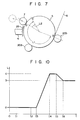
- Fig. 7 is a sectional view showing the platen roller and neighboring components for illustrating a paper sheet loading operation of the first embodiment;
- Fig. 8 is a block diagram showing a control circuit of the first embodiment;
- Fig. 9 is a flow chart for explaining the paper sheet loading operation of the first embodiment;
- Fig. 10 is a graph showing the position of a paper sheet changing with time in the first embodiment;
- Fig. 11 is a sectional view showing a platen roller and neighboring components in a second embodiment of the invention;
- Fig. 12 is a block diagram showing a control circuit of the second embodiment; and
- Fig. 13 is a flow chart explaining the paper sheet loading operation of the second embodiment.
- Now, an embodiment of the printing apparatus according to the invention will be described. Fig. 1 is a perspective view showing a first embodiment of the invention. There is shown a printer body 1 having a
horizontal guide bar 2 for guiding acarriage 3 with aprinting head 4. While the'carriage 3 is driven for reciprocal movement by a carriage motor (not shown), and aplaten roller 5 is driven for rotation in the forward and reverse directions by a platen motor (not shown), printing is done by theprinting head 4 on apaper sheet 6 wound on theplaten roller 5. This embodiment adopts a wire-dot impact printing system using an ink ribbon 4a mounted on thecarriage 3. The winding of thepaper sheet 6 round theplaten roller 5 is effected bypaper bail rollers 7 which are in contact with an upper portion of theplaten roller 5. Thepaper bail rollers 7 are rotatably mounted on a paper bail bar 7a. The paper bail bar 7a can assume two positions, i.e., one in contact with theplaten roller 5 and the other not in contact with theplaten roller 5. When the paper bail bar 7a is in contact with theplaten roller 5, thepaper sheet 6 is pressed against theplaten roller 5 by thepaper bail rollers 7. When the paper bail bar 7a is not in contact with the platen roller, thepaper bail rollers 7 are spaced apart from theplaten roller 5.Friction rollers 20a and 20b are provided in contact with a lower portion of the platen roller 5 (thefriction roller 20b being shown in Fig. 7). Thepaper sheet 6 is fed between theplaten roller 5 andfriction rollers 20a and 20b. Thepaper sheet 6 is initially set on a hopper (not shown) and then fed into the apparatus with the rotation of theplaten roller 5. - Fig. 2 is a sectional view showing part of a right frame la of the printer body 1 shown in Fig. 1. A
shaft 12 is rotatably connected to the right frame la and asupport plate 11 fixed to the right frame la. Aroller release lever 10, which is integral with ashaft 12, is shown. An upper portion of theroller release lever 10, projecting from the printer body 1, is manually operable. One end of theshaft 12 projects outwardly from the right frame la. Secured by ascrew 14 to the projecting end of theshaft 12 is adrive arm 13 extending parallel to the right frame la. Aroller 15 is rotatably mounted by apin 16 on the free end of thedrive arm 13 such that it extends parallel to theshaft 12. Thepaper bail rollers 7 are brought into contact with and separated from theplaten roller 5 by operating theroller release lever 10, as will be described in detail later, and, as such, are also referred to as rollers of theroller release lever 10. - Figs. 3 to 7 are sectional views showing part of the printer of Fig. 1 as viewed from the right side. As shown in Figs. 3 and 5, the
roller release lever 10 carries aroller 17 rotatably mounted on its lower portion near theplaten roller 5. Integral with it are a protuberance 10a, formed on the side of its lower portion opposite theplaten roller 5, and also astopper 10b, formed at the lower end. - A
release arm 18 is rotatably mounted on the right frame la beneath theroller release lever 10. Therelease arm 18 has an upper end portion 18a engaging theroller 17 and alower end portion 18b in contact with aleaf spring 19 secured to the right frame la, theleaf spring 19 biasing therelease arm 18 in a clockwise direction. - The protuberance 10a of the
roller lease lever 10 is in contact with aleaf spring 21 secured to the right frame la. It is urged by theleaf spring 21 in the clockwise direction so that theroller lease lever 10 is held in the position shown in Fig. 3 with thestopper 10b in contact with therelease arm 18. When theroller release lever 10 is turned to the position shown in Fig. 5, theroller 17 strikes and is stopped by the upper end portion 18a of therelease arm 18. At this time, theroller release lever 10 is held at the position shown in Fig. 5, with theroller release lever 10 being held in the clockwise direction by a bent portion 21a of theleaf spring 21. - The
shaft 12 of theroller release lever 10 has an integral peripheral protuberance 10c. Apaper bail switch 22 is secured to the right frame la at a position corresponding to the protuberance lOc. Thepaper bail switch 22 is "on" when theroller release lever 10 is at the position of Fig. 3, and it is "off" when theroller release lever 10 is at the position of Fig. 5. - The
paper bail rollers 7 are rotatably mounted on the paper bail bar 7a, the opposite ends of which are, in turn, mounted on respectivepaper bail arms 8 rotatably mounted on the right and left frames la and lb of the printer body 1. As shown in Figs. 4 and 6, aspring 25 is provided between asupport 23 fixed to the right (or left) frame la (or lb) and asupport 24 fixed to the associatedpaper bail arm 8. Thepaper bail arms 8 are urged by thespring 25 such that thepaper bail rollers 7 are pushed against theplaten roller 5 when thepaper bail rollers 7 are close to theplaten roller 5. In contrast thepaper bail rollers 7 are held in contact with thestopper 26 when thepaper bail rollers 7 are separated from theplaten roller 5. - A
link 27 is rotatably mounted by apin 27b on the right frame la. Thelink 27 has aslot 27a formed in its end portion in which thesupport 24 is engaged. The other end of thelink 27 is formed with anotch 28 in which theroller 15 provided on thedrive arm 13 is engaged. Thenotch 28 has a first sloping edge 28a sloping upwardly toward the right, and a third sloping edge 28c sloping downwardly to the right from the first sloping edge portion 28a. - A
paper guide 29 is mounted on thecarriage 3 at a predetermined distance from theplaten roller 25. Thepaper sheet 6, having been fed out from theplaten roller 5, is guided by thepaper guide 29 upwardly through and between theprinting head 4 andplaten roller 5. Thepaper guide 29 has a shape complementary to the outer periphery of theplaten roller 5. - Fig. 7 is a schematic sectional view showing the
platen roller 5 and nearby components and illustrating the operation of loading a paper sheet in the first embodiment. As shown in the Figure, thepaper sheet 6 is pinched between theplaten roller 5 andfriction rollers 20a and 20b, and is fed between theplaten roller 5 andprinting head 4 by the rotation of thefriction rollers 20a and 20b which rotate with the rotation of theplaten roller 5. - Fig. 8 is a block diagram showing a control circuit of the first embodiment.
Paper bail switch 22 is connected to asystem bus 42 via an I/O port 40. ACPU 44 is also connected to thesystem bus 42, and an output signal of thepaper bail switch 22 is fed to theCPU 44. TheCPU 44 generates, according to this output signal, driving signals for driving aplaten motor 46 which drives the platen roller for loading a paper sheet, and acarriage motor 48 which drives the carriage toward the center of the paper sheet. The driving signals from theCPU 44 are fed to the platen andcarriage motors drivers drivers carriage motors system bus 42 are further connected aROM 54, aRAM 56 and atimer 58. In theROM 54 are stored programs which are executed in theCPU 44. TheRAM 56 is used for temporarily storing data during program execution. In thetimer 58 waiting periods of various operations are set, with the timer counting the residual times of these waiting periods. - The operation of the first embodiment will now be described with reference to the flow chart of Fig. 9 and graph of Fig. 10. The flow chart of Fig. 9 illustrates an automatic paper sheet loading operation in the form of an interrupt operation with respect to the main operation of the printer. In step S2 it is determined whether the
paper bail roller 7 is not in contact with theplaten roller 5. This check is done by checking whether thepaper bail switch 22, noted above, is "off". It is assumed that the paper bail bar 7a is released from theplaten'roller 5 by the operator after a paper sheet is set on the hopper. When thepaper sheet 6 is set on the hopper, its leading end is in position a shown in Fig. 7. If thepaper bail roller 7 is in contact with theplaten roller 5, the program returns to step S22 of the printer's main operation. If the paper bail bar 7a is released from theplaten roller 5, step S4 is executed, in which it is determined whether both the platen andcarriage motors carriage motor 48 is controlled to move thecarriage 3 to the center of the paper sheet. The period of movement of the carriage is between instants tl and t2 shown in Fig. 10. With this action, thepaper sheet 6 can be wound on theplaten roller 5 by thepaper sheet guide 29 provided on theprinting head 4. In a subsequent step, step S8, a waiting period, which is a constant period, is set in thetimer 58. This is done because there is a time delay between the instant when the paper bail bar 7a is released from theplaten roller 5 and the instant when thepaper bail switch 22 is turned off. In a subsequent step, S10, it is determined whether the waiting period has expired. When the waiting period (between instants t2 and t3 shown in Fig. 10) has expired, step S12 is executed and theplaten motor 46 is rotated in the normal direction (i.e., clockwise direction in Fig. 7) for a constant period. During this period (between instants t3 and t4 in Fig. 10), theplaten roller 5 is rotated by an amount Ll, as shown in Fig. 7, so that the leading end of thepaper sheet 6 reaches the position c. It is assumed that thepaper bail roller 7 is subsequently brought to a state in contact with theplaten roller 5 by the operator. In a subsequent step, S14, a constant period is set in thetimer 58. This is done in order that the subsequent operation be executed after the lapse of the constant time even if thepaper bail roller 7 is not in contact with theplaten roller 5. In a subsequent step, S16, it is determined whether thepaper bail roller 7 is in contact with theplaten roller 5. If thepaper bail roller 7 is in contact with theplaten roller 5, step S18 is immediately executed. Since the leading end of thepaper sheet 6 has passed the position of the paper bail bar 7a, with thepaper bail roller 7 being in contact with theplaten roller 5, thepaper sheet 6 is securely pinched between thepaper bail rollers 7 andplaten roller 5. If the paper bail bar 7a is released from theplaten roller 5, it is determined whether the waiting period (between instants t4 and t5 shown in Fig. 10) has expired in step 20. When it is determined that the waiting period has expired, step S18 is executed in which theplaten motor 46 is rotated in the reverse direction for a constant period. During this period (between instants t5 and t6 in Fig. 10) theplaten roller 5 is rotated in reverse by an amount of L2 shown in Fig. 7. This brings to an end the loading of thepaper sheet 6. Since the leading end of thepaper sheet 6 is accurately positioned between theplaten roller 5 andpaper bail roller 7, thepaper sheet 6 is perfectly wound on theplaten roller 5 and the waste area of thepaper sheet 6, which is not provided for printing, can be minimized. Subsequently, the program returns to the main operation (step S22). - As has been shown, automatic loading of the paper sheet can be obtained by merely incorporating a single
paper bail switch 22 for detecting the contact of thepaper bail roller 7 with theplaten roller 5 and an input circuit thereof. In other words, the paper bail bar 7a must be manually contacted with or separated from theplaten roller 5, and it is this manual operation that is detected, making it possible to omit an extra operation of turning on a load switch; hitherto a necessity. - Now, a second embodiment of the invention will be described. In the preceding first embodiment, the paper bail bar is released from the
platen roller 5 by the operator when a paper sheet is set on the hopper. However, since there is no means for detecting the presence or absence of the paper sheet on the hopper, it is possible that the paper bail roller may be in contact with theplaten roller 5 without any paper sheet set on the hopper. In such a case, idle paper loading is caused with the start of rotation of the platen roller. In addition, it is likely that overlap loading after a paper sheet has been loaded may occur. The second embodiment is an improvement over the first embodiment in order to prevent the occurrence of such undesired operations. Fig. 11 shows an essential part of the second embodiment. Fig. 11 corresponds to Fig. 7 showing the first embodiment. In the second embodiment, ahopper 60 is provided with a slit or an opening, and a no-paper detector 62 is provided to detect the presence or absence of a paper sheet on thehopper 60. Thedetector 62 is made of a member having a restoring property, e.g., a spring. When apaper sheet 6 is set on thehopper 60, themember 62 is retracted by thesheet 6 to turn on a switch (not shown), whereby the setting of the paper sheet is detected. When there is no paper sheet set on the hopper, the member is in its advanced position, and the switch is "off", detecting the absence of a paper sheet. The other mechanical constructions are the same as in the first embodiment. - Fig. 12 is a block diagram showing a control circuit of the second embodiment. This control circuit is the same as that in the first embodiment except for that a no-
paper detector 62 is further connected to asystem bus 42 via an I/O port 64. - The operation of the second embodiment will now be described with reference to the flow chart of Fig. 13. The operation of the second embodiment includes the same operation as that of the first embodiment, and steps corresponding to those in the flow chart of Fig. 9 are designated by like reference symbols and are not described further. The automatic paper loading operation, like that of the first embodiment, is started when it is detected in step S2 that the paper bail bar has been released from the
platen roller 5. In the case of the first embodiment, the driving of the carriage and platen motors is started as soon as the paper bail par is released from theplaten roller 5. In the second embodiment, however, after it is detected in step S4 that the motors are stopped, it is determined in step S30 whether there is a paper sheet that has been loaded in the printer. This is done by checking whether a load flag is set, it being set after the completion of paper sheet loading, and reset when the paper sheet is discharged from the printer, as described later. When the load flag is reset, i.e., when there is no paper sheet loaded in the printer, it is determined in step S32 whether apaper sheet 6 is set on thehopper 60. With the retraction of the spring member of the no-paper detector 62, it is detected that apaper sheet 6 is set on thehopper 60. That is, when and only when it is detected that there is no loaded paper sheet in the printer but that there is a paper sheet set on thehopper 60, the carriage and platen motors are driven in steps S6 through S18 to load the paper sheet. When the reverse rotation of the platen roller in step S18 is completed, a load flag is set in step S34. In a subsequent step, S36, it is determined whether there is a paper discharge request. If a decision "NO" yields in step S2 or S4, or a decision "YES" yields in step S30 or S32, the step S36 is immediately executed. If the discharge of paper is not necessary, the program goes back to the main operation step S22. If it is necessary to discharge a paper sheet, step S38, in which the platen motor is rotated in the normal direction for a predetermined period of time, is executed, whereby the paper sheet is discharged. In a subsequent step, S40, the load flag is reset to permit the loading of the next paper sheet. The program then returns to the main operation step 822. - In the second embodiment, as described above, the loading operation is prevented if no paper sheet is set on the hopper or there remains a loaded paper sheet in the printer. Thus, idle paper feeding and overlap loading is eliminated.
- As has been described in the foregoing, according to the invention, it is possible to provide a printing apparatus having excellent operability and wherein a cut paper sheet is automatically loaded merely by separating the paper bail bar from the platen roller.
- The above embodiments of the invention are by no means limitative, and various changes and modifications are possible. For example, the roller release lever for releasing or separating the paper bail bar from the platen roller may be omitted, and the paper bail bar may be directly separated by hand. Further, the paper bail switch and no-paper detector may be variously changed in construction.
Claims (8)
1. A printing apparatus comprising a paper bail roller (7) and a platen roller (5) contacting each other to pinch and feed a paper sheet, characterized by comprising:
means (22) for detecting whether said paper bail roller (7) is in contact with said platen roller (5); and
paper loading means (44, 46) for rotating said platen roller (5) in the normal direction at a first predetermined angle when said detecting means (22) detects that said paper bail roller (7) is not in contact with said platen roller (5), and then rotating said platen roller (5) in the reverse direction at a second predetermined angle.
2. The printing apparatus according to claim 1, characterized in that said paper loading means (44, 46) rotates the platen roller in the reverse direction at said second predetermined angle when it is detected by said detecting means (22) that the paper bail roller is in contact with the platen roller after the platen roller has been rotated in the normal direction at said first predetermined angle.
3. The printing apparatus according to claim 1, characterized in that said paper loading means (44, 46) rotates the platen roller in the reverse direction at said second predetermined angle when a predetermined period of time elapses after the platen roller has been rotated in the normal direction at said first predetermined angle.
4. A printing apparatus comprising a hopper (60) for setting a cut paper sheet thereon, a platen roller (5) for feeding said cut paper sheet set on said hopper (60), and a paper bail bar (7a) having a paper bail roller (7) used in conjunction with the platen roller (5) to secure the cut paper sheet against the platen roller, characterized by further comprising:
first detecting means (62) for detecting whether a cut paper sheet is set on the hopper (60);
second detecting means (44) for detecting whether a cut paper sheet is secured against the platen roller (5);
third detecting means (22), interlocked to the paper bail roller, for detecting whether the paper bail roller (7) is in contact with the platen roller (5); and
paper loading means (44, 46) for rotating the platen roller in the normal direction at a first predetermined angle when said first detecting means detects that a cut paper sheet is set on the hopper, said second detecting means detects that no cut paper sheet is secured against the platen roller and said third detecting means detects that the paper bail roller is not in contact with the platen roller, and then for rotating the platen roller in the reverse direction at a second predetermined angle.
5. The printing apparatus according to claim 4, characterized in that said paper loading means (44, 46) rotates the platen roller in the reverse direction at said second predetermined angle when it is detected by said third detecting means (22) that the paper bail roller is in contact with the platen roller after the platen roller has been rotated in the normal direction at said first predetermined angle.
6. The printing apparatus according to claim 4, characterized in that said paper loading means (44, 46) rotates the platen roller in the reverse direction at said second predetermined angle when a predetermined period of time elapses after the platen roller has been rotated in the normal direction at said first predetermined angle.
7. The printing apparatus according to claim 4, characterized in that a printing head (4), reciprocal along said platen roller (5), is provided, said printing head being brought to a position corresponding to the center of a cut paper sheet (6) in the width direction thereof before rotation of the platen roller in the normal direction at said first predetermined angle, said printing head (4) including a guide (29) provided on its front for causing the cut paper sheet (6) to be wound on the platen roller (5) when the platen roller (5) is rotated in the normal direction at said first predetermined angle.
8. A method of loading a cut paper sheet in a printing apparatus characterized by comprising the steps of:
setting a cut paper sheet on a hopper;
releasing a paper bail roller from a platen roller;
rotating the platen roller in the normal direction at a first predetermined angle when the release of the paper bail roller from the platen roller is detected;
urging the paper bail roller against the platen roller; and
rotating the paper bail roller in the reverse .direction at a second predetermined angle.
Applications Claiming Priority (4)
| Application Number | Priority Date | Filing Date | Title |
|---|---|---|---|
| JP18183984A JPS6158772A (en) | 1984-08-31 | 1984-08-31 | Printer |
| JP181857/84 | 1984-08-31 | ||
| JP181839/84 | 1984-08-31 | ||
| JP18185784A JPS6158775A (en) | 1984-08-31 | 1984-08-31 | Printer |
Publications (1)
| Publication Number | Publication Date |
|---|---|
| EP0173139A1 true EP0173139A1 (en) | 1986-03-05 |
Family
ID=26500849
Family Applications (1)
| Application Number | Title | Priority Date | Filing Date |
|---|---|---|---|
| EP85109934A Ceased EP0173139A1 (en) | 1984-08-31 | 1985-08-07 | Printing apparatus |
Country Status (3)
| Country | Link |
|---|---|
| US (1) | US4702632A (en) |
| EP (1) | EP0173139A1 (en) |
| CA (1) | CA1244371A (en) |
Cited By (5)
| Publication number | Priority date | Publication date | Assignee | Title |
|---|---|---|---|---|
| DE3709127A1 (en) * | 1986-03-26 | 1987-10-01 | Seiko Epson Corp | AUTOMATIC PAPER FEEDER FOR PRINTER |
| US4780014A (en) * | 1986-11-26 | 1988-10-25 | Alps Electric Co., Ltd. | Paper feeding controlling method for a printer including printing at the leading edge of the paper |
| EP0288089A2 (en) * | 1987-04-23 | 1988-10-26 | Brother Kogyo Kabushiki Kaisha | Recording paper transporting device in a recording apparatus |
| DE4138873A1 (en) * | 1990-11-27 | 1992-06-04 | Tokyo Electric Co Ltd | PAPER FEEDER |
| CN110701983A (en) * | 2019-11-19 | 2020-01-17 | 中国兵器装备集团自动化研究所 | Changeable turned angle measuring device of same pivot multi-angle measuring range |
Families Citing this family (8)
| Publication number | Priority date | Publication date | Assignee | Title |
|---|---|---|---|---|
| JPS63207671A (en) * | 1987-02-24 | 1988-08-29 | Alps Electric Co Ltd | Automatic paper feed controlling system for printer |
| US4808019A (en) * | 1987-05-29 | 1989-02-28 | Hewlett-Packard Company | Unified paper path printer |
| JP2676061B2 (en) * | 1989-02-07 | 1997-11-12 | スター精密株式会社 | Printer bail device |
| US5346322A (en) * | 1989-04-24 | 1994-09-13 | Brother Kogyo Kabushiki Kaisha | Printing device having paper feed control |
| JPH0342262A (en) * | 1989-07-08 | 1991-02-22 | Brother Ind Ltd | Printer |
| US5133611A (en) * | 1989-10-19 | 1992-07-28 | Canon Kabushiki Kaisha | Recording apparatus |
| JPH04126274A (en) * | 1990-09-18 | 1992-04-27 | Brother Ind Ltd | printer |
| JP2751621B2 (en) * | 1990-10-31 | 1998-05-18 | ブラザー工業株式会社 | Printer |
Citations (2)
| Publication number | Priority date | Publication date | Assignee | Title |
|---|---|---|---|---|
| GB2055768A (en) * | 1979-07-30 | 1981-03-11 | Ricoh Kk | Automatic sheet feeding system in printing apparatus |
| WO1982001514A1 (en) * | 1980-11-04 | 1982-05-13 | Wang Laboratories | Paper insertion and feeding controlled by upper paper bail |
Family Cites Families (17)
| Publication number | Priority date | Publication date | Assignee | Title |
|---|---|---|---|---|
| US2566930A (en) * | 1948-07-23 | 1951-09-04 | Ibm | Paper bail mechanism for typewriters |
| US3430748A (en) * | 1966-11-04 | 1969-03-04 | Gwynn J Parri | Paper feeder coordinated with platen |
| US4113244A (en) * | 1975-04-15 | 1978-09-12 | Kurt Ruenzi | Apparatus for automatically feeding individual sheets from a stack through an office machine |
| US4266880A (en) * | 1978-09-26 | 1981-05-12 | International Business Machines Corporation | Paper insertion apparatus |
| JPS5625488A (en) * | 1979-08-09 | 1981-03-11 | Canon Inc | Printer |
| JPS56144983A (en) * | 1980-04-15 | 1981-11-11 | Brother Ind Ltd | Typewriter |
| JPS56162677A (en) * | 1980-05-20 | 1981-12-14 | Toshiba Corp | Paper feeder |
| JPS5745084A (en) * | 1980-09-01 | 1982-03-13 | Canon Inc | Printer |
| US4386864A (en) * | 1980-11-04 | 1983-06-07 | Wang Laboratories, Inc. | Selective paper insertion and feeding means for individual sheet printing apparatus |
| US4486108A (en) * | 1980-11-06 | 1984-12-04 | Ricoh Company Ltd. | Semi-automatic paper insertion apparatus |
| JPS5784885A (en) * | 1980-11-14 | 1982-05-27 | Usac Electronics Ind Co Ltd | Leading-end protruding method for slip form medium in printer |
| JPS57151385A (en) * | 1981-03-17 | 1982-09-18 | Canon Inc | Paper feed mechanism |
| DE3133297A1 (en) * | 1981-08-22 | 1983-03-03 | Olympia Werke Ag, 2940 Wilhelmshaven | METHOD AND DEVICE FOR GUIDING PAPER IN WRITING OR SIMILAR OFFICE MACHINES |
| JPS5863486A (en) * | 1981-10-12 | 1983-04-15 | Ricoh Co Ltd | Semi-automatic paper setting system for printer |
| IT1155264B (en) * | 1982-02-03 | 1987-01-28 | Olivetti & Co Spa | DOCUMENT INTRODUCER |
| JPS5924682A (en) * | 1982-08-03 | 1984-02-08 | Tokyo Juki Ind Co Ltd | Printer paper setting device |
| JPS59188464A (en) * | 1983-04-11 | 1984-10-25 | Tokyo Electric Co Ltd | Printer |
-
1985
- 1985-08-07 EP EP85109934A patent/EP0173139A1/en not_active Ceased
- 1985-08-07 CA CA000488254A patent/CA1244371A/en not_active Expired
- 1985-08-14 US US06/765,500 patent/US4702632A/en not_active Expired - Fee Related
Patent Citations (2)
| Publication number | Priority date | Publication date | Assignee | Title |
|---|---|---|---|---|
| GB2055768A (en) * | 1979-07-30 | 1981-03-11 | Ricoh Kk | Automatic sheet feeding system in printing apparatus |
| WO1982001514A1 (en) * | 1980-11-04 | 1982-05-13 | Wang Laboratories | Paper insertion and feeding controlled by upper paper bail |
Cited By (7)
| Publication number | Priority date | Publication date | Assignee | Title |
|---|---|---|---|---|
| DE3709127A1 (en) * | 1986-03-26 | 1987-10-01 | Seiko Epson Corp | AUTOMATIC PAPER FEEDER FOR PRINTER |
| US4780014A (en) * | 1986-11-26 | 1988-10-25 | Alps Electric Co., Ltd. | Paper feeding controlling method for a printer including printing at the leading edge of the paper |
| EP0288089A2 (en) * | 1987-04-23 | 1988-10-26 | Brother Kogyo Kabushiki Kaisha | Recording paper transporting device in a recording apparatus |
| EP0288089A3 (en) * | 1987-04-23 | 1990-07-04 | Brother Kogyo Kabushiki Kaisha | Recording paper transporting device in a recording apparatus |
| US5071274A (en) * | 1987-04-23 | 1991-12-10 | Brother Kogyo Kabushiki Kaisha | Recording paper transporting device for aligning top print line margin and cutting line |
| DE4138873A1 (en) * | 1990-11-27 | 1992-06-04 | Tokyo Electric Co Ltd | PAPER FEEDER |
| CN110701983A (en) * | 2019-11-19 | 2020-01-17 | 中国兵器装备集团自动化研究所 | Changeable turned angle measuring device of same pivot multi-angle measuring range |
Also Published As
| Publication number | Publication date |
|---|---|
| CA1244371A (en) | 1988-11-08 |
| US4702632A (en) | 1987-10-27 |
Similar Documents
| Publication | Publication Date | Title |
|---|---|---|
| EP0173139A1 (en) | Printing apparatus | |
| EP1093928B1 (en) | Roll-paper holder for a printer | |
| US6185478B1 (en) | Printing apparatus, control method for a printing apparatus, and recording medium for recording a control program for a printing apparatus | |
| JP2697276B2 (en) | Printer | |
| US4802778A (en) | Carriage drive control device in a printing device | |
| EP0313404B1 (en) | Automatic paper loading apparatus for printer having paper bail actuating device | |
| EP0202129B1 (en) | Feeding apparatus for printing medium | |
| JPH0764101B2 (en) | Line feed method and single-cut set device in printer | |
| KR100415608B1 (en) | Method for preventing paper jam in printer and apparatus therefor | |
| JP3444055B2 (en) | Paper feeding mechanism | |
| JPS60171183A (en) | Printer | |
| US5020929A (en) | Paper feed device | |
| JP3097705B2 (en) | Printer | |
| JPS60217192A (en) | Printer | |
| JP2615838B2 (en) | Printer automatic paper feed system | |
| JP2006198859A (en) | Recording apparatus and recording apparatus control method | |
| JPH01206077A (en) | Printing device | |
| JP2771646B2 (en) | Method for determining the number of steps of the motor for opening and closing the paper holding roller | |
| JP3642070B2 (en) | Printing apparatus, printing system using the same, and method for controlling the printing apparatus | |
| JP2582417B2 (en) | Printer | |
| JPS58205788A (en) | Typewriter | |
| JPH0336072A (en) | Recording apparatus | |
| JPS63112179A (en) | Recorder | |
| JPH0299362A (en) | Recorder | |
| JPH0223354B2 (en) |
Legal Events
| Date | Code | Title | Description |
|---|---|---|---|
| PUAI | Public reference made under article 153(3) epc to a published international application that has entered the european phase |
Free format text: ORIGINAL CODE: 0009012 |
|
| 17P | Request for examination filed |
Effective date: 19850904 |
|
| AK | Designated contracting states |
Kind code of ref document: A1 Designated state(s): DE FR GB |
|
| 17Q | First examination report despatched |
Effective date: 19870601 |
|
| STAA | Information on the status of an ep patent application or granted ep patent |
Free format text: STATUS: THE APPLICATION HAS BEEN REFUSED |
|
| 18R | Application refused |
Effective date: 19881013 |
|
| RIN1 | Information on inventor provided before grant (corrected) |
Inventor name: TAKETANI, MITSUHIROC/O PATENT DIVISION |