EP0150370B1 - Méthode et dispositif pour la détermination rapide d'une tension de référence synchronisée avec le secteur pour un convertisseur piloté par le secteur après une panne de secteur - Google Patents
Méthode et dispositif pour la détermination rapide d'une tension de référence synchronisée avec le secteur pour un convertisseur piloté par le secteur après une panne de secteur Download PDFInfo
- Publication number
- EP0150370B1 EP0150370B1 EP84115092A EP84115092A EP0150370B1 EP 0150370 B1 EP0150370 B1 EP 0150370B1 EP 84115092 A EP84115092 A EP 84115092A EP 84115092 A EP84115092 A EP 84115092A EP 0150370 B1 EP0150370 B1 EP 0150370B1
- Authority
- EP
- European Patent Office
- Prior art keywords
- frequency
- vector
- transformation
- network
- transformed
- Prior art date
- Legal status (The legal status is an assumption and is not a legal conclusion. Google has not performed a legal analysis and makes no representation as to the accuracy of the status listed.)
- Expired
Links
- 238000000034 method Methods 0.000 title claims description 30
- 230000001360 synchronised effect Effects 0.000 title claims description 8
- 239000013598 vector Substances 0.000 claims description 231
- 230000009466 transformation Effects 0.000 claims description 124
- 230000010355 oscillation Effects 0.000 claims description 38
- 238000009499 grossing Methods 0.000 claims description 34
- 230000033228 biological regulation Effects 0.000 claims description 22
- 230000001105 regulatory effect Effects 0.000 claims description 7
- 230000001629 suppression Effects 0.000 claims description 4
- 239000013078 crystal Substances 0.000 claims description 3
- 230000000694 effects Effects 0.000 claims description 3
- 239000010453 quartz Substances 0.000 claims description 3
- VYPSYNLAJGMNEJ-UHFFFAOYSA-N silicon dioxide Inorganic materials O=[Si]=O VYPSYNLAJGMNEJ-UHFFFAOYSA-N 0.000 claims description 3
- 230000003321 amplification Effects 0.000 claims 1
- 238000003199 nucleic acid amplification method Methods 0.000 claims 1
- 230000006870 function Effects 0.000 description 16
- 230000010363 phase shift Effects 0.000 description 8
- 230000008569 process Effects 0.000 description 6
- 238000006243 chemical reaction Methods 0.000 description 4
- 238000012935 Averaging Methods 0.000 description 3
- 230000004913 activation Effects 0.000 description 3
- 238000013459 approach Methods 0.000 description 3
- 230000006399 behavior Effects 0.000 description 3
- 230000015572 biosynthetic process Effects 0.000 description 3
- 230000015556 catabolic process Effects 0.000 description 3
- 238000005259 measurement Methods 0.000 description 3
- 238000012546 transfer Methods 0.000 description 3
- 230000001052 transient effect Effects 0.000 description 3
- 230000005540 biological transmission Effects 0.000 description 2
- 238000012545 processing Methods 0.000 description 2
- 238000000844 transformation Methods 0.000 description 2
- 230000001960 triggered effect Effects 0.000 description 2
- 206010034016 Paronychia Diseases 0.000 description 1
- 230000008859 change Effects 0.000 description 1
- 238000012937 correction Methods 0.000 description 1
- 230000001419 dependent effect Effects 0.000 description 1
- 238000001514 detection method Methods 0.000 description 1
- 238000011161 development Methods 0.000 description 1
- 230000018109 developmental process Effects 0.000 description 1
- 230000005283 ground state Effects 0.000 description 1
- 238000012544 monitoring process Methods 0.000 description 1
- 230000004044 response Effects 0.000 description 1
- 230000000284 resting effect Effects 0.000 description 1
- 230000000717 retained effect Effects 0.000 description 1
- 238000010408 sweeping Methods 0.000 description 1
- 238000011144 upstream manufacturing Methods 0.000 description 1
- 230000004304 visual acuity Effects 0.000 description 1
Images


Classifications
-
- H—ELECTRICITY
- H02—GENERATION; CONVERSION OR DISTRIBUTION OF ELECTRIC POWER
- H02M—APPARATUS FOR CONVERSION BETWEEN AC AND AC, BETWEEN AC AND DC, OR BETWEEN DC AND DC, AND FOR USE WITH MAINS OR SIMILAR POWER SUPPLY SYSTEMS; CONVERSION OF DC OR AC INPUT POWER INTO SURGE OUTPUT POWER; CONTROL OR REGULATION THEREOF
- H02M7/00—Conversion of AC power input into DC power output; Conversion of DC power input into AC power output
-
- H—ELECTRICITY
- H02—GENERATION; CONVERSION OR DISTRIBUTION OF ELECTRIC POWER
- H02M—APPARATUS FOR CONVERSION BETWEEN AC AND AC, BETWEEN AC AND DC, OR BETWEEN DC AND DC, AND FOR USE WITH MAINS OR SIMILAR POWER SUPPLY SYSTEMS; CONVERSION OF DC OR AC INPUT POWER INTO SURGE OUTPUT POWER; CONTROL OR REGULATION THEREOF
- H02M1/00—Details of apparatus for conversion
- H02M1/08—Circuits specially adapted for the generation of control voltages for semiconductor devices incorporated in static converters
- H02M1/084—Circuits specially adapted for the generation of control voltages for semiconductor devices incorporated in static converters using a control circuit common to several phases of a multi-phase system
-
- H—ELECTRICITY
- H02—GENERATION; CONVERSION OR DISTRIBUTION OF ELECTRIC POWER
- H02M—APPARATUS FOR CONVERSION BETWEEN AC AND AC, BETWEEN AC AND DC, OR BETWEEN DC AND DC, AND FOR USE WITH MAINS OR SIMILAR POWER SUPPLY SYSTEMS; CONVERSION OF DC OR AC INPUT POWER INTO SURGE OUTPUT POWER; CONTROL OR REGULATION THEREOF
- H02M7/00—Conversion of AC power input into DC power output; Conversion of DC power input into AC power output
- H02M7/02—Conversion of AC power input into DC power output without possibility of reversal
- H02M7/04—Conversion of AC power input into DC power output without possibility of reversal by static converters
- H02M7/12—Conversion of AC power input into DC power output without possibility of reversal by static converters using discharge tubes with control electrode or semiconductor devices with control electrode
- H02M7/145—Conversion of AC power input into DC power output without possibility of reversal by static converters using discharge tubes with control electrode or semiconductor devices with control electrode using devices of a thyratron or thyristor type requiring extinguishing means
- H02M7/155—Conversion of AC power input into DC power output without possibility of reversal by static converters using discharge tubes with control electrode or semiconductor devices with control electrode using devices of a thyratron or thyristor type requiring extinguishing means using semiconductor devices only
- H02M7/162—Conversion of AC power input into DC power output without possibility of reversal by static converters using discharge tubes with control electrode or semiconductor devices with control electrode using devices of a thyratron or thyristor type requiring extinguishing means using semiconductor devices only in a bridge configuration
- H02M7/1623—Conversion of AC power input into DC power output without possibility of reversal by static converters using discharge tubes with control electrode or semiconductor devices with control electrode using devices of a thyratron or thyristor type requiring extinguishing means using semiconductor devices only in a bridge configuration with control circuit
- H02M7/1626—Conversion of AC power input into DC power output without possibility of reversal by static converters using discharge tubes with control electrode or semiconductor devices with control electrode using devices of a thyratron or thyristor type requiring extinguishing means using semiconductor devices only in a bridge configuration with control circuit with automatic control of the output voltage or current
Definitions
- the invention relates to a method for determining a grid-synchronous reference voltage for a control set of a grid-guided converter, in particular in the case of an AC voltage network which is subject to harmonics after a grid fault.
- the invention further relates to a device for performing the method according to the preamble of claim 14.
- a device for in-phase smoothing of vector component voltages is known from German published application 20 19 263.
- Two voltages are perceived as orthogonal components of a vector in a spatially fixed orthogonal reference system and fed to the vector input of a vector rotator.
- Two normalized voltages are input to the angle signal input of the vector rotator, which as sine and cosine of a variable angle correspond to the Cartesian spatial coordinates of a unit vector rotating with a transformation frequency.
- These normalized voltages serve as transformation elements for a coordinate transformation, so that the vector rotator at the output supplies the orthogonal components of the vector in a reference system that rotates synchronously with the unit vector.
- the quotient of these circumferential orthogonal components corresponds to the tangent of the angular coordinate of the transformed vector and is fed to a controller, the output signal of which is input as a frequency-proportional control voltage to a sine and cosine generator to form the normalized voltages for the angular signal input of the vector rotator. It is thereby achieved that the rotating unit vector tracks the predetermined vector so that the angular coordinate in the rotating reference system becomes zero.
- the transformed component of the vector which is parallel to the unit vector, is fed to a further controller, the output signal of which, when the angular coordinate is adjusted, represents the magnitude of the vector. Multiplying this amount by the outputs of the sine-cosine function generator then results in the smoothed orthogonal, spatially fixed vector components that are sought.
- EP-A-117 421 belongs to the state of the art in technology to expand this method to a low-noise frequency measurement on a multi-phase line system for electrical power transmission.
- z. B. the frequency of an AC voltage network are detected
- two voltage signals are formed from the measured values, which define an actual vector describing the mains voltage system as orthogonal components in a fixed reference system.
- These spatially fixed vector components are converted into two frequency-transformed orthogonal co-system components by a frequency transformation which is carried out by the vector rotator mentioned.
- the frequency of the transform elements i.e.
- the frequency of the unit vector entered at the angle signal input of the vector rotator is now determined by specifying a setpoint for the angular coordinate of the transformed vector and correcting the control deviation of the angular coordinate from this setpoint. It is provided that the frequency of the transformation elements is precontrolled with the nominal frequency of the AC voltage network, which represents the approximate mean value of the network frequency. As long as the AC voltage network is present, the frequency of the frequency-variable transformation elements corresponds to the sought network frequency in the adjusted state, so that the oscillation frequency is tapped directly at the frequency control input of the sine-cosine encoder as the frequency measurement value sought.
- the recurring voltage does not only consist of an abruptly switched on fundamental oscillation, but also upper frequencies with an unknown frequency as well as transient processes with various unknown frequencies and decaying amplitudes occur, these harmonic components representing an asymmetrically decaying system.
- These harmonic frequencies are not necessarily integer multiples of the mains frequency, even if they usually begin with the second harmonic frequency and often contain pronounced harmonic vibrations of third and higher atomic numbers.
- the invention is based on the object of specifying a method and a device which make it possible to provide a grid-synchronous reference voltage as soon as possible after a grid fault has ended, with which the control rate of a grid-guided converter can be controlled without fear of commutation errors .
- a first vector rotator transforms the fixed components into a rotating reference system, which is based on the orthogonal axes ⁇ ', ⁇ '.
- the actual vector has the transformed components U ⁇ "U ⁇ " which define the actual value vector in the form of the transformed vector U ⁇ ' ⁇ ⁇ .
- a first smoothing element 3 forms the components from the transformed components by smoothing and which are referred to as "transformed co-system components" and a vector establish.
- the polar angular coordinate of this vector is in the following with designated.
- a vector analyzer 5 supplies as a phase difference generator at its angle signal output an angle signal pair cos shown as a double arrow sin for this angular coordinate where the individual signal sin can be compared at a comparison point 6 with a setpoint sin ⁇ *.
- this control deviation of the sine functions corresponds to the control deviation of the corresponding angle.
- a control amplifier is connected downstream, by means of which the control deviation can be corrected with a control loop gain that increases disproportionately for increasing values.
- this non-linear control amplifier 7 is connected in parallel with an integral controller 8 for generating an integrating gain component.
- the phase difference generator is followed by an actuator which forms the fixed components of the rotating reference axis a ', i.e. the variables cos (p s and sin (p s) , which are passed as transformation elements to the angle signal input 2a of the first vector rotator 2'.
- this actuator consists of an integrator 9 fed by the amplified control deviation, which is followed by a sine-cosine encoder 10.
- a changeover switch 11 is provided, by means of which the frequency specification of the transformation elements can be switched over between a control system with a stored frequency value f o in the event of a network fault (open switch 11) and a control system (closed switch 11), so that the Control after the return of the AC voltage network can correct the control deviation formed by the phase difference generator.
- the stored frequency value f o which can in particular be set to the nominal frequency of the network, is also applied to the frequency control input 16 of the actuator in the case of the undisturbed mains voltage, which precontrols the transformation frequency with the stored frequency f o , which corresponds to a predetermined mean value for the network frequency.
- the switch 11 is actuated by a control device 12 as a function of a fault signal formed by a network monitor 13, which indicates the start and end of the network fault.
- a control device 12 from the system deviation that is, for. B. the angle signal of the vector analyzer 5
- the phase ⁇ s of the transformation elements corresponds in the balanced state, as will be explained later, directly to the phase of the co-system fundamental oscillation of the network. If it is sufficient to detect only the co-system basic oscillation phase as the network-synchronous reference signal, z. B. the signal pair cos ⁇ s , sin ⁇ s can be tapped directly at output 14. If, on the other hand, the amplitude of the co-system fundamental oscillation is also required for the reference signal, the transformation elements can be weighted with this amplitude. This is done in FIG. 1 in that the magnitude output of the vector analyzer 5 is fed to a multiplier 4a 'for the transformation elements.
- the fundamental oscillation of the voltage system also contains a negative system, which should be taken into account when forming the network psychronic reference voltage.
- the components and that of the multiplier 4a 'as spatially fixed orthogonal components of the co-system vector are provided, subtracted from the corresponding spatially fixed components U a and U ß of the actual vector U ⁇ ß .
- the difference vector U ⁇ ⁇ - formed by the corresponding subtraction stage 18 is transformed into an oppositely rotating reference system by means of a second vector rotator, which is likewise acted upon by the transformation elements cos ⁇ s , sin ⁇ s .
- This second reference system is based on the Cartesian axes ⁇ "and ⁇ ", the a "axis rotating at the frequency -f s , ie including the angle -cp s with respect to the fixed a-axis.
- ⁇ system the actual vector has the orthogonal components U ⁇ "and Uß", which describe a vector U ⁇ " ⁇ ", and the difference vector has the orthogonal components of a vector U ⁇ " ⁇ "
- Another downstream vector rotator 4 "now transforms these negative sequence components and back into the fixed a, ß system and thus supplies the fixed components U “a and U” ß of the negative system vector the fundamental vibration.
- An addition point 19 is used for vector addition of the two vectors and so that now the sum vector is available, which describes the entire basic oscillation and to which the corresponding fundamental oscillations UR U s and U T of the phase voltages can be assigned by a 2/3 converter 20.
- Figure 2 shows a slightly modified embodiment in which the components designated by the reference numerals of Figure 1 are unchanged.
- a vector rotator 4' inverse to the first vector rotator 2 '. This vector rotator transforms the components and from the a ', ß' system rotating at the frequency of the transformation elements back into the fixed system, so it delivers the same output signal as the multiplier 4a 'without the magnitude coordinate itself would be needed.
- this coordinate of magnitude is formed in a Cartesian / polar coordinate converter 5a and can be tapped at the output 21.
- the angular coordinate from can be used directly with the setpoint ⁇ * to form the control deviation.
- the pre-control of the transformation frequency with the stored frequency f o is the addition point 16 Better understanding in Figure 2 placed at the output of the integrator 9 and serves to control the integrator output signal, which determines the transformation phase cp s of the frequency transformations, with the pilot control angle ⁇ 0, which in turn must be variable with the stored frequency value f o and its phase if necessary, can be shifted by a constant additional phase angle ⁇ ⁇ z in accordance with the short-term activation of the additional frequency value f z .
- phase ⁇ p s of the transformation elements is thus present at the output of the adder 16 and is converted into cos ⁇ s , sin ⁇ s by a polar / Cartesian converter 10a in accordance with the function generator 10.
- the 3/2 converter 1 and the inverse 2/3 converter represent the relationship between the individual phase voltages and the Cartesian vector components that describe these voltages, according to respectively.
- Such a computing element which is acted upon by input signals corresponding to Cartesian coordinates and determines the polar coordinates, is known as a Cartesian / polar "k / p converter" and z. B. described in German Offenlegungsschrift 28 16 661.
- the inverse conversion of polar coordinates to Cartesian coordinates can be carried out by a p / k converter in accordance with German laid-open specification 28 16 614.
- the angle coordinate ⁇ ⁇ of the vector U ⁇ described by U a and U ß can be understood as the phase angle of the voltage U R or as the phase of the entire mains voltage system. If this phase of the mains voltage system is further understood as the angle between the actual vector U ⁇ and the axis a of the Cartesian coordinate system a, ⁇ , a coordinate system that is fixed in space is thereby determined.
- the vector rotator 2 ' is formed therefrom the transformed orthogonal components
- the vector U ⁇ thus rotates uniformly in the a, ß system, and if the transformation phase cp s in the steady, balanced state is synchronous with the network phase ⁇ ⁇ , the vector rotator 2 'supplies two constant transformed orthogonal components.
- the transformed network phase ⁇ is therefore constant. Consequently, the smoothing element 2 '(e.g. a filter for each component) is not loaded and the average values at its output are equal to the input values.
- the vector rotator 4 now transforms this vector, referred to as the "co-system vector", from the rotating a', ß 'system back into the fixed a, ß system.
- This inverse transformation corresponds to the transformation (4), only the sign of the transformation angle ⁇ s being negative, ie the vector rotator 4 'requires the same transformation elements, only the assignment and sign of the transformation elements to the corresponding vector rotation inputs being changed.
- the k / p converter thus forms the corresponding polar vector components (corresponding to the Cartesian / polar coordinate conversion listed below) from the output variables of the smoothing element 3 '(ie the Cartesian vector components according to the first definition equations).
- the coordinate converter 5a thus delivers for small angle values ⁇ 0) the actual angle value sin required to track the transformation angle cp s which is derived from the actual tensions of the network through this special type of averaging.
- the second vector rotator 4 transforms the Cartesian components and this vector back into the fixed a, ß system and therefore forms the fixed orthogonal components and of the co-system: with the fixed angular coordinate
- the multiplier 4a 'of FIG. 1 and the vector rotator 4' of FIG. 2 are equivalent in terms of their output signals, which are used as vectors describe the corresponding, non-standardized mains voltages.
- the components 9, 10 in FIG. 1 and 9, 10a in FIG. 2 represent a pilot-controlled vector oscillator.
- the integrator 9 for example a frequency-controlled oscillator with a downstream, resettable counter
- ⁇ O 2 ⁇ f o x dt
- a downstream function transmitter e.g. a read-only memory
- Activation of the control deviation ( ⁇ * - or (sin ⁇ p * sin means that this frequency and thus the angle is changed until the control deviation disappears.
- the fundamental frequency in a symmetrical system has been described.
- Such symmetrical systems have two degrees of freedom (amplitude and phase), with the individual voltages of this voltage system arising from one another only by a phase shift.
- the fundamental oscillation of the mains voltage system (fundamental frequency f) is composed of individual harmonic oscillations of this frequency, each of which has two degrees of freedom, ie the following applies:
- the transformed co-system vector rests in this co-rotating a ', ⁇ ' system, its transformed orthogonal components corresponding to the mean values formed by the smoothing element 3 '.
- the transformed negative system vector rotates in the rotating a ', ⁇ ' system in opposite directions and at twice the frequency, so its transformed orthogonal components are averaged away by the smoothing element 3 '. Therefore, the smoothing member 3 'provides the smoothed vector actually in the co-rotating a ', ß' system the current co-system, which after transformation back into the spatially fixed a, ⁇ system the co-system vector indicates.
- the entire basic vibration can be determined according to (7) or (8), this can be done in that the actual vector U ⁇ also in a counter-rotating reference system with the reference axes ⁇ ", ⁇ " is transformed, whereby a transformed vector Ua " ⁇ ⁇ with the transformed orthogonal components U ⁇ " and U ⁇ "is obtained.
- ⁇ "system the negative sequence system now has constant orthogonal components, corresponding to a negative sequence vector resting in the negative sequence system while the co-system represents alternating variables, corresponding to a vector rotating at double frequency
- the transformation of the actual vector U ⁇ into the a ", ⁇ " system corresponds to the transformation (4) with a transformation angle -cp s .
- This is exactly the transformation which the vector rotator 4 'already described has to carry out, so that such a vector rotator with the transformation elements cos ⁇ s , -sin cp s can be used for the transformation into the a ", ß" system.
- the back transformation from the a ", ß" system into the fixed a, ß system is the same as the transformation using the vector rotator 2 'already described.
- Figures 1 and 2 show with the corresponding vector rotators 2 "and 4" and the intervening smoothing element 3 "for the two transformed orthogonal components the necessary building blocks for determining the opposite system, the addition element 19 adding the two vectors vectorially.
- the 2/3 converter 20 supplies the individual stresses according to (8) according to the relationship (2).
- the negative sequence amplitude is usually only small compared to the positive sequence amplitude. Therefore, the dimensioning of the smoothing element 3 'to determine the co-system presents no difficulties. However, the smoothing element 3 "must suppress the high vibrations generated by the co-system in the a", ⁇ "system. This is facilitated by the fact that not the transformed orthogonal components of the entire actual vector are smoothed, but rather the one belonging to the difference between the overall system and co-system Vector U ⁇ " ⁇ ..
- This vectorial difference is advantageously carried out already in the fixed reference frame by the subtraction element 18 upstream of the vector rotator 2 ".
- the control device 12 of FIG. 1 stores the frequency value f s that occurred last at the frequency control input of the vector oscillator 9, 10, which corresponds to the actual fundamental frequency at this point in time, and this stored value for the frequency control of the transformation elements during the occurrence of the network fault the disturbance used. Since this controlled operation is only required during the mains disturbance, the switch 11 can also be designed as a changeover switch, which switches over from controlled operation (frequency control through the control deviation) to controlled operation (frequency control through the stored frequency value).
- this predetermined frequency value can also be applied to the frequency control input of the vector oscillator 9, 10 in controlled operation, so that, in the case of an existing network (closed switch 11), only the slight control deviation between the network frequency and the nominal frequency has to be corrected.
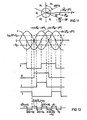
- the dashed lines in FIG. 4 represent for t> t, the course cos cp s and sin cp s for the case that the tracking control is not switched on when the network returns, that is to say the transformation elements are not synchronized with the recurring fundamental oscillation of the network.
- orthogonal components shown for the recurring network each completely describe the current network status, i.e. they always contain the complete information about the frequencies, phase positions and amplitudes of the fundamental frequency and all harmonic frequencies that are present in the recurring network.
- the associated spatially fixed vector of this harmonic therefore does not describe a uniform rotation with a circular locus in the a, ß system, but a rotation with an elliptical locus.
- this harmonic is present in the individual phase voltages with different amplitudes and phase positions, that is to say represents a highly asymmetrical system. Such asymmetries are of course also possible for the other frequencies, but are less clearly visible in FIG.
- the vector rotator 2 transforms the orthogonal components U a and U ß into a rotating a', ⁇ 'system, the a' axis of which does not fall in the direction of the vector _Uass. If you now disassemble the orthogonal components formed by the vector rotator 2 'and transformed into the non-synchronous ⁇ ', ⁇ 'system, you will first find a major part with only slightly variable orthogonal components. This is the co-system fundamental oscillation of the network, which in the a, ß system is given and in the non-synchronously rotating a ', ß' system appears and is variable with the difference frequency of nominal frequency and mains frequency. (Fig. 6).
- the fundamental oscillation counter-system which in the spatially fixed a, ß system as a vector rotating in opposite directions with the fundamental frequency appears, occurs in the rotating a 'ß' system as a vector rotating in opposite directions at double frequency.
- FIG. 6 naturally also contains the third-order harmonic negative-system vector which rotates in the rotating a ' ⁇ ' system at four times the fundamental frequency. Upper frequencies of higher order have been omitted in FIG. 6 for better understanding.
- the vector rotator 2 ' only has to carry out multiplications and can therefore carry out the transformation within a few microseconds. Therefore, the output signals of the vector rotator 2 'actually represent the superimposition of the signals shown in FIG. 6 practically immediately after network return.
- the smoothing element 3 ' is designed as a filter, which above all has to suppress the harmonics shown in FIG.
- certain asymmetry and harmonic ratios can be expected when the network returns.
- the filter 3 ' must be designed primarily for a double fundamental frequency (corresponding to the rotating negative system vector rotating in the a', ⁇ '-system).
- the counter-oscillation of good vibrations is relatively low or decays quickly, whereas upper frequencies, which are not an integral multiple of the network frequency, are particularly disruptive.
- the filter is advantageously designed in such a way that it shields the most critical harmonics (as a rule, at least the critical harmonic with the lowest atomic number) to such an extent that their residual amplitude is less than 2% of the fundamental vibration amplitude.
- a simple follow-up element with the complex transfer function 1 / (1 + sx T 1 ) is not sufficient.
- FIG. 7 and FIG. 8 show the structure and transfer function of a preferred smoothing element which is tuned to the suppression of a critical harmonic at 120 Hz.
- FIG. 9 shows the output signal of the filter 3 'with broken lines for the area of the network return for t 1 ... t 2 .
- the output signals are in turn normalized to the actual co-system amplitude, and the exponentially slowly increasing signal curve shows that the filter only slowly increases to the cos values and sin settles in.
- the final values of these signals would then only change slowly in the steady state.
- these curves correspond to a locus of the vector the length of which gradually increases to the actual amplitude in accordance with the swinging in of the filter and the direction of which swings in accordance with the behavior of the vector analyzer about the direction given by the transformation angle.
- the transformation angle which is finally tapped as a measured value for the phase position of the fundamental, is initially not related to the actual fundamental system.
- the transformation angle is adjusted to the actual phase of the fundamental oscillation system. Therefore, at time t 3, the measured values run into the values of the actual orthogonal components of the fundamental system. Deviations between the solid lines for the actual voltage curve and the dashed lines for the measured values are now only due to the counter-oscillation system and the harmonics of the actual values. In the time interval t 2. . . t 3 therefore approaches the locus of the vector described by the measured values to the actual mains voltage vector to the extent that the phase-locked loop regulates the rotating a'-axis to the direction of the actual vector.
- the procedure is such that in addition to the control deviation, a quantized value of the control deviation is formed and that the control or regulation of the transformation frequency is temporarily intervened in such a way that the phase ⁇ s of the transformation elements is adjusted by this quantized value.
- This process is controlled by the control device 12, which is explained for an analog technique in FIGS. 11 to 13.
- the associated circuit is shown in Figure 12.
- the output signals are cos and sin of the vector analyzer 5 limit value indicators GA, GB, GC and GD, which form the signals A, B, C and D according to FIG.
- the outputs of these limit detectors are linked with each other via a logic circuit, this logic circuit having its own output for each angular range A 1 ... A 5 (an output assigned to the range A o corresponding to the control deviation zero is not necessary).
- the logical combination ensures that a signal is only present at the output that corresponds to the currently occupied angular range. This creates an analog angle discriminator 30.
- FIG. 14 shows the further part of the control device 12 in which the output signals A 1 to A 5 of this angle discriminator are processed further.
- the network monitor 13 provides z. B. by monitoring the network amplitude, as can be determined, for example, by a vector analyzer 31 connected to the 3/2 converter, the breakdown of the network is fixed.
- a flip-flop 32 is set, by which the switch 11 is opened (time t o ).
- a delay stage 33 first ensures that a z. B. time t 1 ... t 2 required for starting the vector analyzer 5 is waited before the fast synchronization of the transformation elements takes place.
- a pulse shaper 34 then delivers a short pulse at this time t 2 , by means of which AND gates G 1 ... G 5 are released, which are connected to the outputs of the angle discriminator 30.
- Each output of these gates is connected to a timer with the activation times T 1 ... T 5 . Since only the signal output An belonging to the instantaneous angular range leads to a signal at time t 2, only a certain time element to be assigned to the respective angular range is triggered.
- An OR gate 35 combines the output signals of the time stages T 1 ... T 5 into a switch-on signal for a switch 36. This switch 36 thus only connects during the period n belonging to the current angular range An.
- T o one Constant voltage source with an adder 17, to which the additional frequency value f z thus formed is now applied to the stored frequency value f o .
- FIG. 16 schematically shows a somewhat simplified embodiment of the invention, in which the actual vector U ⁇ generated by the 3/2 converter 1 is not further processed in Cartesian coordinates, but by means of a k / p converter 41 into its polar coordinates U and ⁇ ⁇ is converted.
- the transformation into the coordinate system rotating with the transformation frequency f s takes place in that the transformation angle ⁇ s is subtracted directly from the angle coordinate ⁇ ⁇ (subtraction point 42).
- the two components 41 and 42 now supply the actual vector U ⁇ in the form of its transformed polar coordinates, likewise in the rotating ' ⁇ , ⁇ ' system. Consequently, the same physical information is obtained as by the vector rotator 2 'in FIG.
- the smoothing element 3' would have the same input and output variables in both cases for an almost symmetrical network of the form U a ⁇ U. cos ⁇ a , U ß m U sin ⁇ ⁇ thus the inputs U ⁇ . ⁇ U cos ( ⁇ ⁇ - ⁇ s ), U ⁇ , ⁇ U sin. ( ⁇ ⁇ - ⁇ s ) and the outputs
- the smoothing element 3 'thus provides mean values in which, compared to FIGS. 1 and 2, the other systems superimposed on the co-system are weighted differently, so that the mean values of the polar coordinates of the transformed actual vector (FIG 16) and the mean values of the transformed orthogonal components of the vector (FIGS. 1 and 2) approach each other.
- the inverse transformation of the vector formed by the averaging can be formed simply by adding the transformation angle cp s and the averaged angle coordinate at the addition point 43.
- values are present at terminals 44 and 45 which, according to the inaccuracies mentioned, describe the amount and phase position of a vector which is approximately synchronous with the network.
- a corresponding sine-cosine encoder can be connected downstream of terminal 44.
- the fixed Cartesian coordinates can be formed by a downstream multiplier, corresponding to the multiplier 4a 'in FIG. 1.
- This digitized variant of fast synchronization can also be applied to the device according to FIG. 1.
- an integrator 9 z. B. uses a voltage controlled crystal oscillator. Quartz oscillators have an excellent frequency stability, which can only be changed within certain limits by applying an additional control voltage. In the uncontrolled state, the quartz oscillator oscillates at the constant frequency f o , to which a subsequent pulse counter is tuned so that it is reset at the counter reading corresponding to a full period of the nominal frequency.
- a vector analyzer is functionally a k / p converter for the formation of magnitude and angle and a downstream sine / cosine encoder for converting the angle into the angle functions
- a k / p converter can ultimately be used alone in the arrangement just described, to form the angular coordinate used for digitization directly from the output signals of the smoothing element 3 '.
- the preferred embodiment of FIG. 17 provides for the vector analyzer to be retained.
- the component is sin at the angle signal output of the vector analyzer, on the one hand, the control controller 7, 8 is directly connected as the actual value, on the other hand, both angle functions supplied by the vector analyzer are fed to an analog / digital converter 52.
- the conversion of the angle functions into the corresponding angle itself is carried out digitally by a microcomputer 53.
- this digital angle formation is also a k / p conversion, it is easy to carry out due to the standardized input voltages.
- the microcomputer 53 is only in operation when the network monitor 13 reports the beginning and end of a network fault and therefore the switch 11 must be operated in the manner already described.
- the integrator 9 of the figure is replaced by the mentioned crystal oscillator 9a, whose fundamental frequency is f o , with the counter 50 connected downstream.
- the data bus at the output of the microcomputer only gives a one-time pulse to the adder 51 at time t, which is just the digital value of the angular coordinate corresponds and causes the aforementioned adjustment of the transformation angle.
- the counter 51 uses the digital angle cp s to address the read-only memory 54, whose output variables cos ⁇ s , sin ⁇ s, by means of a multiplying digital / analog converter 4b 'into the analog signals corresponding to the output signal of the multiplier 4a 'in Fig. 1, and converted together with the components of the opposing system are processed further.
- the points p 1 ... P7 now represent the end points of the vector, which is determined by the output signals of the vector analyzer 5 in each case 1 ... 7 ms after the network returns. At this point, switch 11 in FIG. 17 is still open. If the vector analyzer were to work ideally, as explained with the dashed lines in FIG. 9, these points would practically coincide with the point U o , since the inputs of the vector analyzer increase practically exponentially in accordance with the settling of the filter 3 ', this exponentially increases Increase due to the formation of quotients
- the time t 2 at which the switch 11 is closed is thus reached after only 7 ms.
- This has the effect that, due to the high computing speed of the microcomputer 53, the a'-axis in the fixed system is moved almost immediately by the angle belonging to the point P7 , so that the a'-axis coincides with the actual network vector at this point in time. Since the tracking control is now switched on, the a 'axis now moves synchronously with the actual vector of the fundamental oscillation, the harmonics being filtered out.
- the transformation element cos (p s then describes the mitsystem fundamental oscillation of the phase voltage U R or the mains voltage system normalized to the actual mitsystem fundamental oscillation amplitude.
- the digital / analog converter 4b In order to arrive at the actual fundamental oscillation from these standardized values, the digital / analog converter 4b 'uses 17 multiplies the corresponding transformation element in each case by the magnitude coordinate determined by the vector analyzer 5. Accordingly, a detected fundamental vibration vector results at time t 7 that matches the actual vector in its direction, its amount however, it still deviates from the actual fundamental oscillation vector to the extent that the still oscillating filter 3 'detects a measurement value which is still incorrect for the actual fundamental vibration amplitude.
Landscapes
- Engineering & Computer Science (AREA)
- Power Engineering (AREA)
- Ac-Ac Conversion (AREA)
- Control Of Eletrric Generators (AREA)
- Inverter Devices (AREA)
Claims (18)
dérivée des composantes de la fréquence transformée, et une valeur de consigne prédéterminée (ϕ*) de la phase (figures 1, 2 et 16: amplificateurs de réglage 7, 8; circuits de réglage 9 et 10 ou 10a); - en tant que vecteur de la tension de référence, synchronisé avec le réseau, on prélève soit le vecteur de transformation normalisé par rapport à une amplitude constante (figures 1 et 2: cos cps, sin cps, sortie 14), soit on prélève les composantes
ainsi que par les phases opératoires suivantes dans le cas d'un dérangement du réseau:


Applications Claiming Priority (2)
| Application Number | Priority Date | Filing Date | Title |
|---|---|---|---|
| DE3346291 | 1983-12-21 | ||
| DE19833346291 DE3346291A1 (de) | 1983-12-21 | 1983-12-21 | Verfahren und vorrichtung zum schnellen ermitteln einer netzsynchronen referenzspannung fuer einen netzgefuehrten stromrichter nach einer netzstoerung |
Publications (3)
| Publication Number | Publication Date |
|---|---|
| EP0150370A2 EP0150370A2 (fr) | 1985-08-07 |
| EP0150370A3 EP0150370A3 (en) | 1985-08-21 |
| EP0150370B1 true EP0150370B1 (fr) | 1987-07-22 |
Family
ID=6217616
Family Applications (1)
| Application Number | Title | Priority Date | Filing Date |
|---|---|---|---|
| EP84115092A Expired EP0150370B1 (fr) | 1983-12-21 | 1984-12-10 | Méthode et dispositif pour la détermination rapide d'une tension de référence synchronisée avec le secteur pour un convertisseur piloté par le secteur après une panne de secteur |
Country Status (5)
| Country | Link |
|---|---|
| US (1) | US4665474A (fr) |
| EP (1) | EP0150370B1 (fr) |
| JP (1) | JPS60156275A (fr) |
| CA (1) | CA1224244A (fr) |
| DE (2) | DE3346291A1 (fr) |
Families Citing this family (14)
| Publication number | Priority date | Publication date | Assignee | Title |
|---|---|---|---|---|
| DE3664180D1 (en) * | 1985-04-09 | 1989-08-03 | Siemens Ag | Method and device to determine the phase position of a multiphase measure value system |
| DE3632178A1 (de) * | 1986-09-22 | 1988-03-31 | Siemens Ag | Verfahren und vorrichtung zur schnellen erfassung von netzfehlern |
| DE3701219C1 (de) * | 1987-01-17 | 1988-09-01 | Guenter Frohn | Verfahren zum Innenschleifen von Bohrungen mit geringem Durchmesser-/Laengenverhaeltnis |
| EP0308765A1 (fr) * | 1987-09-24 | 1989-03-29 | Siemens Aktiengesellschaft | Procédé et dispositif de détermination de la valeur réelle de l'angle d'extinction d'un onduleur |
| EP0315871A1 (fr) * | 1987-11-12 | 1989-05-17 | Siemens Aktiengesellschaft | Procédé et dispositif de contrôle d'un redresseur de courant sur un réseau asymétrique |
| FI90294C (fi) * | 1990-05-03 | 1994-01-10 | Kone Oy | Menetelmä tasasuuntaajan tasajännitteen säätämiseksi |
| JP2889133B2 (ja) * | 1994-11-02 | 1999-05-10 | 関西電力株式会社 | 電力変換器の制御装置 |
| DE4443428A1 (de) * | 1994-12-06 | 1996-06-13 | Siemens Ag | Verfahren und Vorrichtung zur Erzeugung eines beliebigen m-phasigen Stromsystems n-ter Ordnung einer umrichtergespeisten Einrichtung |
| US6239997B1 (en) * | 2000-09-01 | 2001-05-29 | Ford Motor Company | System for connecting and synchronizing a supplemental power source to a power grid |
| US6919650B2 (en) * | 2002-05-31 | 2005-07-19 | Ballard Power Systems Corporation | Hybrid synchronization phase angle generation method |
| CN100420118C (zh) * | 2003-09-23 | 2008-09-17 | 艾劳埃斯·乌本 | 风力设备及其操作方法 |
| US8248038B2 (en) * | 2009-05-27 | 2012-08-21 | Empire Technology Development Llc | Synchronous generator protection |
| US9966889B2 (en) * | 2013-05-12 | 2018-05-08 | Infineon Technologies Ag | Optimized control for synchronous motors |
| US12224591B2 (en) * | 2022-05-16 | 2025-02-11 | Ge Infrastructure Technology Llc | Virtual impedance current limiting control for grid forming inverter-based resources |
Family Cites Families (8)
| Publication number | Priority date | Publication date | Assignee | Title |
|---|---|---|---|---|
| US3824437A (en) * | 1969-08-14 | 1974-07-16 | Siemens Ag | Method for controlling asynchronous machines |
| DE2106789C3 (de) * | 1971-02-12 | 1978-03-02 | Siemens Ag, 1000 Berlin Und 8000 Muenchen | Einrichtung zur Steuerung oder Regelung des Ständerstromvektors einer Asynchronmaschine |
| CH531272A (de) * | 1970-08-18 | 1972-11-30 | Siemens Ag | Einrichtung zur Steuerung netzgeführter Stromrichter, insbesondere für Anlagen zur Hochspannungs-Gleichstromübertragung |
| US3922594A (en) * | 1974-10-15 | 1975-11-25 | Lorain Prod Corp | Control system for phase displacement regulator circuits |
| DE2813253C2 (de) * | 1978-03-28 | 1982-12-16 | Siemens AG, 1000 Berlin und 8000 München | Schaltungsanordnung zum Anfahren eines fahrweggebundenen elektrischen Triebfahrzeuges mit einem eisenlosen synchronen Linearmotor |
| DE2816661C3 (de) * | 1978-04-17 | 1980-10-23 | Siemens Ag, 1000 Berlin Und 8000 Muenchen | Koordinatenwandler zur Umwandlung von kartesischen VektorgröBen in polare Vektorgrößen |
| DE3303454A1 (de) * | 1983-02-02 | 1984-08-02 | Siemens AG, 1000 Berlin und 8000 München | Verfahren und vorrichtung zur rauscharmen frequenzmessung bei einer mehrphasigen elektrischen leistungsuebertragung |
| JPS59169369A (ja) * | 1983-03-16 | 1984-09-25 | Toshiba Corp | 交流電流制御装置 |
-
1983
- 1983-12-21 DE DE19833346291 patent/DE3346291A1/de not_active Withdrawn
-
1984
- 1984-12-10 EP EP84115092A patent/EP0150370B1/fr not_active Expired
- 1984-12-10 DE DE8484115092T patent/DE3464997D1/de not_active Expired
- 1984-12-13 US US06/681,257 patent/US4665474A/en not_active Expired - Fee Related
- 1984-12-19 CA CA000470486A patent/CA1224244A/fr not_active Expired
- 1984-12-20 JP JP59270595A patent/JPS60156275A/ja active Pending
Also Published As
| Publication number | Publication date |
|---|---|
| EP0150370A2 (fr) | 1985-08-07 |
| JPS60156275A (ja) | 1985-08-16 |
| CA1224244A (fr) | 1987-07-14 |
| DE3464997D1 (en) | 1987-08-27 |
| EP0150370A3 (en) | 1985-08-21 |
| DE3346291A1 (de) | 1985-07-04 |
| US4665474A (en) | 1987-05-12 |
Similar Documents
| Publication | Publication Date | Title |
|---|---|---|
| EP0150370B1 (fr) | Méthode et dispositif pour la détermination rapide d'une tension de référence synchronisée avec le secteur pour un convertisseur piloté par le secteur après une panne de secteur | |
| DE2926378C2 (de) | Schaltungsanordnung zum Wiederanfahren eines verzögerten Induktionsmotors | |
| DE2109491C3 (de) | Dreiphasiger Wechselrichter | |
| DE2929127A1 (de) | Elektrische schaltungsanordnung zum erzeugen einer ausgangsgroesse variabler frequenz | |
| DE3213057C2 (de) | Anordnung zum Regeln des Arbeitsstroms eines über einen Umformer an eine Stromquelle angeschlossenen Gleichstromverbrauchers | |
| EP0134050B1 (fr) | Circuit pour le fonctionnement de lampes de décharge à gaz à haute pression | |
| DE2941191C2 (de) | System zur Erzeugung und Selbstkontrolle des Kurvenverlaufs von Spannung oder Strom beim elektrolytischen Einfärben von eloxiertem Aluminium | |
| DE69024285T2 (de) | Servosteuerungsanordnung für ein System mit Rückführung und Anwendung davon bei Verstärken und Servomechanismen | |
| DE4205300C1 (en) | Digital determination of phase and amplitude of periodic signal in phase locked loop - sampling periodic signal using sampling period to give constant whole number of measured value samples and phase estimates per period | |
| WO2018072791A1 (fr) | Procédé et circuit pour commander un moteur pas à pas | |
| DE4426764C2 (de) | Verfahren zur Ansteuerung eines Pulswechselrichters durch Stellbefehle eines Pulsmustergenerators | |
| WO1987003112A1 (fr) | Circuit de production d'un signal de mesure pour la frequence d'un signal c.a. | |
| DE2010046C3 (de) | Zündsteuergerät für einen netzgeführten Stromrichter | |
| DE3529591A1 (de) | Verfahren und vorrichtung zum betrieb eines wechselrichters | |
| DE3203257A1 (de) | Vorrichtung zum bestimmen der gemeinsamen frequenz zweier unabhaengig veraenderlicher wechselgroessen, insbesondere bei einer drehfeldmaschine | |
| EP0097958B1 (fr) | Procédé et dispositif pour réduire les grandeurs parasites contenues dans un système de grandeurs de sortie d'un organe de régulation et application à un cyclo convertisseur direct à sortie à courant triphasé | |
| EP1816903B1 (fr) | Commutateur variable d'une correction du point zéro | |
| EP0063673B1 (fr) | Circuit pour générer une tension de synchronisation sinusoidale pour l'allumage de thyristors | |
| DE1762872A1 (de) | Schaltungsanordnung zur Phasensynchronisierung | |
| DE2530724C2 (de) | Verfahren zur Verbesserung des dynamischen Führungs- und Störverhaltens eines Stromrichter-Regelkreises | |
| EP0533978B1 (fr) | Méthode et dispositif pour commander un onduleur à impulsions | |
| EP0216224B1 (fr) | Disposition de circuit pour rendre une installation de puissance indépendante de la fréquence du réseau et pour compenser la dispersion des paramètres lors du découpage | |
| DE2832022C2 (fr) | ||
| CH459334A (de) | Schaltungsanordnung zur elektronischen Regelung der Drehzahl einer Antriebsvorrichtung | |
| DE2917380C2 (de) | Synchronisierschaltung, insbesondere von Wechselrichtern |
Legal Events
| Date | Code | Title | Description |
|---|---|---|---|
| PUAI | Public reference made under article 153(3) epc to a published international application that has entered the european phase |
Free format text: ORIGINAL CODE: 0009012 |
|
| PUAL | Search report despatched |
Free format text: ORIGINAL CODE: 0009013 |
|
| AK | Designated contracting states |
Designated state(s): CH DE FR GB LI SE |
|
| AK | Designated contracting states |
Designated state(s): CH DE FR GB LI SE |
|
| 17P | Request for examination filed |
Effective date: 19850925 |
|
| 17Q | First examination report despatched |
Effective date: 19860619 |
|
| GRAA | (expected) grant |
Free format text: ORIGINAL CODE: 0009210 |
|
| STAA | Information on the status of an ep patent application or granted ep patent |
Free format text: STATUS: THE PATENT HAS BEEN GRANTED |
|
| AK | Designated contracting states |
Kind code of ref document: B1 Designated state(s): CH DE FR GB LI SE |
|
| REF | Corresponds to: |
Ref document number: 3464997 Country of ref document: DE Date of ref document: 19870827 |
|
| ET | Fr: translation filed | ||
| PLBE | No opposition filed within time limit |
Free format text: ORIGINAL CODE: 0009261 |
|
| 26N | No opposition filed | ||
| PGFP | Annual fee paid to national office [announced via postgrant information from national office to epo] |
Ref country code: GB Payment date: 19911120 Year of fee payment: 8 |
|
| PGFP | Annual fee paid to national office [announced via postgrant information from national office to epo] |
Ref country code: FR Payment date: 19911217 Year of fee payment: 8 |
|
| PGFP | Annual fee paid to national office [announced via postgrant information from national office to epo] |
Ref country code: SE Payment date: 19911219 Year of fee payment: 8 |
|
| PGFP | Annual fee paid to national office [announced via postgrant information from national office to epo] |
Ref country code: DE Payment date: 19920225 Year of fee payment: 8 |
|
| PGFP | Annual fee paid to national office [announced via postgrant information from national office to epo] |
Ref country code: CH Payment date: 19920324 Year of fee payment: 8 |
|
| PG25 | Lapsed in a contracting state [announced via postgrant information from national office to epo] |
Ref country code: GB Effective date: 19921210 |
|
| PG25 | Lapsed in a contracting state [announced via postgrant information from national office to epo] |
Ref country code: SE Effective date: 19921211 |
|
| PG25 | Lapsed in a contracting state [announced via postgrant information from national office to epo] |
Ref country code: LI Effective date: 19921231 Ref country code: CH Effective date: 19921231 |
|
| GBPC | Gb: european patent ceased through non-payment of renewal fee |
Effective date: 19921210 |
|
| PG25 | Lapsed in a contracting state [announced via postgrant information from national office to epo] |
Ref country code: FR Effective date: 19930831 |
|
| REG | Reference to a national code |
Ref country code: CH Ref legal event code: PL |
|
| PG25 | Lapsed in a contracting state [announced via postgrant information from national office to epo] |
Ref country code: DE Effective date: 19930901 |
|
| REG | Reference to a national code |
Ref country code: FR Ref legal event code: ST |
|
| EUG | Se: european patent has lapsed |
Ref document number: 84115092.3 Effective date: 19930709 |