EP0132077B1 - Thermochromic liquid crystal displays - Google Patents
Thermochromic liquid crystal displays Download PDFInfo
- Publication number
- EP0132077B1 EP0132077B1 EP84304522A EP84304522A EP0132077B1 EP 0132077 B1 EP0132077 B1 EP 0132077B1 EP 84304522 A EP84304522 A EP 84304522A EP 84304522 A EP84304522 A EP 84304522A EP 0132077 B1 EP0132077 B1 EP 0132077B1
- Authority
- EP
- European Patent Office
- Prior art keywords
- display
- liquid crystal
- wall
- grating
- crystal material
- Prior art date
- Legal status (The legal status is an assumption and is not a legal conclusion. Google has not performed a legal analysis and makes no representation as to the accuracy of the status listed.)
- Expired
Links
Images


Classifications
-
- G—PHYSICS
- G02—OPTICS
- G02F—OPTICAL DEVICES OR ARRANGEMENTS FOR THE CONTROL OF LIGHT BY MODIFICATION OF THE OPTICAL PROPERTIES OF THE MEDIA OF THE ELEMENTS INVOLVED THEREIN; NON-LINEAR OPTICS; FREQUENCY-CHANGING OF LIGHT; OPTICAL LOGIC ELEMENTS; OPTICAL ANALOGUE/DIGITAL CONVERTERS
- G02F1/00—Devices or arrangements for the control of the intensity, colour, phase, polarisation or direction of light arriving from an independent light source, e.g. switching, gating or modulating; Non-linear optics
- G02F1/01—Devices or arrangements for the control of the intensity, colour, phase, polarisation or direction of light arriving from an independent light source, e.g. switching, gating or modulating; Non-linear optics for the control of the intensity, phase, polarisation or colour
- G02F1/13—Devices or arrangements for the control of the intensity, colour, phase, polarisation or direction of light arriving from an independent light source, e.g. switching, gating or modulating; Non-linear optics for the control of the intensity, phase, polarisation or colour based on liquid crystals, e.g. single liquid crystal display cells
- G02F1/132—Thermal activation of liquid crystals exhibiting a thermo-optic effect
-
- G—PHYSICS
- G02—OPTICS
- G02F—OPTICAL DEVICES OR ARRANGEMENTS FOR THE CONTROL OF LIGHT BY MODIFICATION OF THE OPTICAL PROPERTIES OF THE MEDIA OF THE ELEMENTS INVOLVED THEREIN; NON-LINEAR OPTICS; FREQUENCY-CHANGING OF LIGHT; OPTICAL LOGIC ELEMENTS; OPTICAL ANALOGUE/DIGITAL CONVERTERS
- G02F1/00—Devices or arrangements for the control of the intensity, colour, phase, polarisation or direction of light arriving from an independent light source, e.g. switching, gating or modulating; Non-linear optics
- G02F1/01—Devices or arrangements for the control of the intensity, colour, phase, polarisation or direction of light arriving from an independent light source, e.g. switching, gating or modulating; Non-linear optics for the control of the intensity, phase, polarisation or colour
- G02F1/13—Devices or arrangements for the control of the intensity, colour, phase, polarisation or direction of light arriving from an independent light source, e.g. switching, gating or modulating; Non-linear optics for the control of the intensity, phase, polarisation or colour based on liquid crystals, e.g. single liquid crystal display cells
- G02F1/133—Constructional arrangements; Operation of liquid crystal cells; Circuit arrangements
- G02F1/1333—Constructional arrangements; Manufacturing methods
- G02F1/133377—Cells with plural compartments or having plurality of liquid crystal microcells partitioned by walls, e.g. one microcell per pixel
-
- G—PHYSICS
- G02—OPTICS
- G02F—OPTICAL DEVICES OR ARRANGEMENTS FOR THE CONTROL OF LIGHT BY MODIFICATION OF THE OPTICAL PROPERTIES OF THE MEDIA OF THE ELEMENTS INVOLVED THEREIN; NON-LINEAR OPTICS; FREQUENCY-CHANGING OF LIGHT; OPTICAL LOGIC ELEMENTS; OPTICAL ANALOGUE/DIGITAL CONVERTERS
- G02F1/00—Devices or arrangements for the control of the intensity, colour, phase, polarisation or direction of light arriving from an independent light source, e.g. switching, gating or modulating; Non-linear optics
- G02F1/01—Devices or arrangements for the control of the intensity, colour, phase, polarisation or direction of light arriving from an independent light source, e.g. switching, gating or modulating; Non-linear optics for the control of the intensity, phase, polarisation or colour
- G02F1/13—Devices or arrangements for the control of the intensity, colour, phase, polarisation or direction of light arriving from an independent light source, e.g. switching, gating or modulating; Non-linear optics for the control of the intensity, phase, polarisation or colour based on liquid crystals, e.g. single liquid crystal display cells
- G02F1/133—Constructional arrangements; Operation of liquid crystal cells; Circuit arrangements
- G02F1/1333—Constructional arrangements; Manufacturing methods
- G02F1/1337—Surface-induced orientation of the liquid crystal molecules, e.g. by alignment layers
-
- G—PHYSICS
- G02—OPTICS
- G02F—OPTICAL DEVICES OR ARRANGEMENTS FOR THE CONTROL OF LIGHT BY MODIFICATION OF THE OPTICAL PROPERTIES OF THE MEDIA OF THE ELEMENTS INVOLVED THEREIN; NON-LINEAR OPTICS; FREQUENCY-CHANGING OF LIGHT; OPTICAL LOGIC ELEMENTS; OPTICAL ANALOGUE/DIGITAL CONVERTERS
- G02F1/00—Devices or arrangements for the control of the intensity, colour, phase, polarisation or direction of light arriving from an independent light source, e.g. switching, gating or modulating; Non-linear optics
- G02F1/01—Devices or arrangements for the control of the intensity, colour, phase, polarisation or direction of light arriving from an independent light source, e.g. switching, gating or modulating; Non-linear optics for the control of the intensity, phase, polarisation or colour
- G02F1/13—Devices or arrangements for the control of the intensity, colour, phase, polarisation or direction of light arriving from an independent light source, e.g. switching, gating or modulating; Non-linear optics for the control of the intensity, phase, polarisation or colour based on liquid crystals, e.g. single liquid crystal display cells
- G02F1/133—Constructional arrangements; Operation of liquid crystal cells; Circuit arrangements
- G02F1/1333—Constructional arrangements; Manufacturing methods
- G02F1/1341—Filling or closing of cells
Definitions
- thermochromic liquid crystal displays use the selective reflection of cholesteric liquid crystal materials. The observed colour is dependent on the cholesteric material pitch and usually varies with temperature.
- thermometry e.g. digital thermometers
- medical applications e.g. diagnoses of vascular disorders
- non-destructive testing e.g. of welding flaws
- radiation sensors e.g. thermal imaging, etc.
- the device has: reliability, with high chemical and photo-chemical stability and physical toughness; accuracy, with repeatable colour calibration; quality of observed colour purity and brightness.
- suitable liquid crystal compounds for example those described in GB-A-1,556,994, GB-A-1,596,012, GB-A-1,596,013, GB-A-1,596,014, GB-A-1,592,161.
- Other requirements are physical i.e. containing the liquid crystal material where needed.
- Most known devices contain liquid crystal material on a supporting substrate.
- An ink is prepared and printed on the substrate. This ink incorporates liquid crystal material in small droplets.
- Two known methods of preparing the ink use micro-encapsulation, and polymerdispersion.
- micro-encapsulation involves encasing droplets of liquid crystal (diameters 5-50 pm) in polymer sheets made from one or a combination of the following: a gelatine-gum arabic system, a polyvinyl alcohol-based system, a zein based system or an amnoblast condensate such as resorcinol-formaldehyde.
- a gelatine-gum arabic system a polyvinyl alcohol-based system
- a zein based system a zein based system
- amnoblast condensate such as resorcinol-formaldehyde.
- the technique of polymerdispersion is similar to the above technique with the difference that the dispersed liquid crystal droplets in the binder polymer film are not first pre-coated with a polymer shell.
- the droplets are located in cavities within a continuous polymer matrix layer.
- US-A-1,161,039 and 3,872,050 describe two different methods of producing the polymerdispersions.
- Liquid crystal material has been arranged to provide colour changes without encapsulation.
- US-A-4,251,137 describes a liquid crystal cell in which a layer of nematic liquid crystal material is contained between cell walls. The inner surface of these walls is profiled in a fine rectangular wave pattern, i.e. a light grating. When an electric field is applied across the layer thickness the refractive index of the liquid crystal changes from that of the zero voltage state. Two different colours are observed depending on the voltage on or off state of the liquid crystal material. The wall surface profile determines the observed colours.
- This device is not thermochromic i.e. does not change colour with temperature.
- thermochromic liquid crystal display comprising a layer of short pitch cholesteric liquid crystal material contained between two walls at least one of which is surface profiled in a fine grating to align the liquid crystal molecules in contact therewith.
- the walls may be flexible or non-flexible, and thick or thin, and combinations thereof.
- Short pitch of the cholesteric material may be defined as a pitch suitable for selectively reflecting light, e.g. a pitch typically 0.2 pm to 0.7 ⁇ m or more.
- the layer of liquid crystal material is 10 11m or more thick e.g. 10-50 ⁇ m.
- Both walls may have surface gratings of equal or different pitch and/or profile.
- one wall has a grating whilst the other wall is untreated or treated to give homeotropic alignment.
- Surface gratings may be provided by embossing thin sheets of plastic material. This grating may have a rectangular, or square, saw tooth, triangular, trapezoidal, sine wave, or approximations to these profiles, sufficient to give a closely spaced series of aligning grooves.
- the display may operate by reflection in which case the rear wall is covered with an absorbing layer or is formed as an absorbing layer.
- the display may be arranged to operate as a narrow band transmission filter by arranging a plurality of displays optically in series.
- An enhanced reflective display may be formed by arranging a half wave plate between two displays, the rear display having an absorbing rear surface.
- a memory effect may be built into the display by providing a very strong surface alignment which tends to prevent molecular realignment after a localised-heating has been removed. Return to the original condition may then be achieved e.g. by local deformation as by flexing.
- Displays may be provided in larger sheets bonded at their edges and spaced apart by spacer pillars formed on embossed sheets of plastic.
- the displays may be of various shapes, large or small, punched out of larger displays; the act of punching being arranged to heat seal the edges.
- the particular liquid crystal material used is selected to give the desired colour at a given temperature. This is achieved by mixing materials to give the required pitch and refractive index at a given temperature. Wavelength of reflected light ( ⁇ ) is proportional to the average of the refractive indices (no + n e )/2, and cholesteric pitch p. Pitch p varies with temperature.
- a thermochromic display cell 1 comprises a thin flexible front wall 2 and a thin flexible rear wall 3 bonded at their edges 4 to enclose a short pitch cholesteric liquid crystal material 5.
- a black absorbing layer 6 e.g. of Gold Black is formed on the rear of the rear wall 3 or the wall itself formed of a black opaque material e.g. black Melinex ® .
- Both walls 2, 3 may be of a 30 ⁇ m thick transparent plastic sheet such as Melinex 301 (I.C.I. material) which is a polyester co-extruded film with an amorphous surface layer which can be embossed. The thickness of this amorphous layer depends upon the size of profile required. For example the layer may be 3 pm or more thick.
- the rear wall 3 of the cell is embossed with a grating 7 shown more clearly in Figure 2.
- This grating 7 has a square or rectangular profile, typical groove width is 0.05 to 12 pm and depth 0.05 to 0.1 pm.
- the front wall 2 is flat and untreated but may also be embossed and the grating aligned non-parallel to the rear grating. Alternatively the front wall 2 may be treated, e.g. by dipping in lecithin to give a homeotropic alignment.
- the cholesteric liquid crystal material 5 is aligned by the grating 7 with the helical axis of the director perpendicular to the walls 2, 3. This results in substantially all the liquid crystal molecules being in the ideal alignment for maximum reflection of a single wavelength.
- the liquid crystal material 5 has a pitch, p, which selectively reflects visible light e.g. light between 380 and 780 nm wavelength.
- suitable materials are B.D.H. catalogue numbers TM 74A, TM 74B, TM 75A, and TM 75B. These are mixed to give a colour and a temperature range as required.
- One example is a mixture giving a colour play of red-blue over a temperature range of 21° to 25.5°C. This is formed of 40% by weight of mixture A + 60% by weight of mixture B.
- Mixture A 30% weight of TM 74A + 70% weight TM 75A.
- Mixture B 30% weight of TM 74B + 70% weight TM 75B.
- a fine tuning of the range and colour may be made by adding small amounts of mixture A, B, TM 74A or TM 75B.
- Liquid crystal material is introduced between the walls by spreading a thin layer e.g. 10 ⁇ m thick over the profiled surface of one wall.
- the other wall is laid over the liquid crystal and the edges sealed e.g. by punching out shapes or pressure and temperature e.g. 100°C where required.
- Suitable materials for mixing are:
- the grating 7 may be formed on the Melinex ® (I.C.I.) by embossing.
- a copper plate or roller is coated on a surface with a nickel plating. This plating is then selectively removed using standard photolithographic techniques to give a square or rectangular profile. Typically the grooves are 0.05 to 12 ⁇ m wide and 0.05-12 ⁇ m deep.
- the nickel layer is coated with a thin, less than 1 pm, layer of a release agent such as Fluorad Surfactant FC 721.
- the plate or roller is heated to about 105-115°C and pressed onto the amorphous surface layer of the Melinex 301 shet. A typical pressure is 3-5 atmospheres (2.9 x 10 5- 4.9 x 10 5 Pa). This forms a fine grating on the Melinex 301.
- the actual colour of reflected light is governed by the cholesteric pitch and refractive index, n
- Figure 3 shows the surface profile of a cell 1 wall for use in larger displays.
- the wall 3 is embossed to give both a grating 7, as in Figure 2, and pillars 9. These pillars help give a reasonably uniform thickness to the complete cell 1.
- the pillars are of square section 25 pm x 25 pm, 25 pm high, and spaced 250-300 11m apart. Two sections of embossed Melinex may be brought into contact and quickly heated to fuse the pillars of one sheet onto the adjacent sheet.
- the cell walls 2, 3 may also be formed by thicker sheets of material, e.g. glass but in these cases the temperature changes are slower and the cell is not so flexible.
- a thin front wall 11 is embossed on its inner surface with a fine grating.
- a fine grating For example a grating of square or sine wave profile with a pitch less than 5 pm e.g. a groove width of less than 2.5 ⁇ m, and with a groove depth of less than 0.1 pm.
- the rear wall 13 is embossed with a coarse profile 14. For example a groove 15 width of 100 pm, a groove depth of 10 ⁇ m to 50 pm, with a gap or web 16 between grooves of 25 pm.
- the grooves in the front and rear walls may be arranged parallel or non-parallel e.g. orthogonal to one another.
- An absorber 6 covers the rear of the rear wall.
- the coarse grating may have grooves 15a extending the whole length of a sheet.
- the grooves may have cross webs 17 to form elongated 15b or square 15c depressions in the wall 13 surface. These depressions may have rounded corners, and may be oval or even circular in plan.
- liquid crystal material is spread over a large sheet 13 having the coarse grating e.g. by silk screen printing, a roller, ink jet printing, or spraying to a depth of about 10 pm.
- the front wall 11, in the form of a large sheet, is placed over the rear wall 13 and the two pressed together with an amount of heating e.g. to 100°C to seal the webs against the front wall.
- an amount of heating e.g. to 100°C to seal the webs against the front wall.
- the coarse grating has cross webs 17 the result is a plurality of closed cells.
- the complete display may then be cut with a knife or scissors into different shapes.
- Different compositions of liquid crystal material may be printed in different areas of the rear wall. These different compositions may be separated by areas of non-liquid crystal material or be left empty.
- the bottom of the groove 15 of the coarse grating may have superimposed thereon a fine grating.
- the grooves may have homeotropic or homogeneous surface alignment treatment.
- a memory effect may be provided by varying the profile of the grating 7, for example decreasing the depth and/or spacing of the grooves to reduce the aligning of liquid crystal molecules.
- One use for the display of this invention is for a thermal imaging system retina onto which an image of a thermal scene is focussed.
- a large number of very small display discs are mounted on a thin support of low lateral thermal conductivity. This separation of discs provides a reticulation and reduces lateral spread of the thermal image. Temperature variations across the retina are observed as different colours representing the thermal scene.
Landscapes
- Physics & Mathematics (AREA)
- Nonlinear Science (AREA)
- Chemical & Material Sciences (AREA)
- Crystallography & Structural Chemistry (AREA)
- General Physics & Mathematics (AREA)
- Optics & Photonics (AREA)
- Mathematical Physics (AREA)
- Spectroscopy & Molecular Physics (AREA)
- Liquid Crystal (AREA)
- Liquid Crystal Substances (AREA)
- Devices For Indicating Variable Information By Combining Individual Elements (AREA)
Description
- This invention relates to thermochromic liquid crystal displays. Such displays use the selective reflection of cholesteric liquid crystal materials. The observed colour is dependent on the cholesteric material pitch and usually varies with temperature.
- Thermochromic displays have many uses. For example thermometry e.g. digital thermometers; medical applications e.g. diagnoses of vascular disorders; non-destructive testing e.g. of welding flaws; radiation sensors e.g. thermal imaging, etc. For all these applications it is important that the device has: reliability, with high chemical and photo-chemical stability and physical toughness; accuracy, with repeatable colour calibration; quality of observed colour purity and brightness. Some of these requirements are chemical and can be solved by use of suitable liquid crystal compounds, for example those described in GB-A-1,556,994, GB-A-1,596,012, GB-A-1,596,013, GB-A-1,596,014, GB-A-1,592,161. Other requirements are physical i.e. containing the liquid crystal material where needed.
- Most known devices contain liquid crystal material on a supporting substrate. An ink is prepared and printed on the substrate. This ink incorporates liquid crystal material in small droplets. Two known methods of preparing the ink use micro-encapsulation, and polymerdispersion.
- The technique of micro-encapsulation is disclosed in US-A-3,585,381. It involves encasing droplets of liquid crystal (diameters 5-50 pm) in polymer sheets made from one or a combination of the following: a gelatine-gum arabic system, a polyvinyl alcohol-based system, a zein based system or an amnoblast condensate such as resorcinol-formaldehyde. A slurry of these capsules in a water/polymer solution gives the 'ink'.
- The technique of polymerdispersion is similar to the above technique with the difference that the dispersed liquid crystal droplets in the binder polymer film are not first pre-coated with a polymer shell. The droplets are located in cavities within a continuous polymer matrix layer. US-A-1,161,039 and 3,872,050 describe two different methods of producing the polymerdispersions.
- There are problems with both micro-encapsulation and polymerdispersion. The observed colour purity and brightness is low partly because only a part of the liquid crystal material is in the best orientation of cholesteric helices for optimum reflection.
- Liquid crystal material has been arranged to provide colour changes without encapsulation. For example US-A-4,251,137 describes a liquid crystal cell in which a layer of nematic liquid crystal material is contained between cell walls. The inner surface of these walls is profiled in a fine rectangular wave pattern, i.e. a light grating. When an electric field is applied across the layer thickness the refractive index of the liquid crystal changes from that of the zero voltage state. Two different colours are observed depending on the voltage on or off state of the liquid crystal material. The wall surface profile determines the observed colours. This device is not thermochromic i.e. does not change colour with temperature.
- The problem of colour purity and low reflectance is solved according to the present invention by a thermochromic liquid crystal display comprising a layer of short pitch cholesteric liquid crystal material contained between two walls at least one of which is surface profiled in a fine grating to align the liquid crystal molecules in contact therewith.
- The walls may be flexible or non-flexible, and thick or thin, and combinations thereof.
- Short pitch of the cholesteric material may be defined as a pitch suitable for selectively reflecting light, e.g. a pitch typically 0.2 pm to 0.7 µm or more.
- Preferably the layer of liquid crystal material is 10 11m or more thick e.g. 10-50 µm.
- Both walls may have surface gratings of equal or different pitch and/or profile. Alternatively one wall has a grating whilst the other wall is untreated or treated to give homeotropic alignment. Surface gratings may be provided by embossing thin sheets of plastic material. This grating may have a rectangular, or square, saw tooth, triangular, trapezoidal, sine wave, or approximations to these profiles, sufficient to give a closely spaced series of aligning grooves.
- The display may operate by reflection in which case the rear wall is covered with an absorbing layer or is formed as an absorbing layer. Alternatively the display may be arranged to operate as a narrow band transmission filter by arranging a plurality of displays optically in series.
- An enhanced reflective display may be formed by arranging a half wave plate between two displays, the rear display having an absorbing rear surface.
- A memory effect may be built into the display by providing a very strong surface alignment which tends to prevent molecular realignment after a localised-heating has been removed. Return to the original condition may then be achieved e.g. by local deformation as by flexing.
- Displays may be provided in larger sheets bonded at their edges and spaced apart by spacer pillars formed on embossed sheets of plastic. Alternatively the displays may be of various shapes, large or small, punched out of larger displays; the act of punching being arranged to heat seal the edges.
- The particular liquid crystal material used is selected to give the desired colour at a given temperature. This is achieved by mixing materials to give the required pitch and refractive index at a given temperature. Wavelength of reflected light (λ) is proportional to the average of the refractive indices (no + ne)/2, and cholesteric pitch p. Pitch p varies with temperature.
- The invention will now be described by way of example only with reference to the accompanying drawings of which:
- Figure 1 is a sectional view of a thermochromic liquid crystal display, not drawn to scale;
- Figure 2 is an enlarged view of part of one wall of Figure 1 showing a profiled inner surface; and
- Figure 3 is a sectional view of an alternative wall, useful in larger displays.
- Figure 4 is a sectional view of an alternative display showing the two walls only; and
- Figure 5 is a perspective view of one wall of the display of Figure 4.
- As shown in Figures 1, A thermochromic display cell 1 comprises a thin flexible front wall 2 and a thin flexible
rear wall 3 bonded at theiredges 4 to enclose a short pitch cholestericliquid crystal material 5. A black absorbinglayer 6 e.g. of Gold Black is formed on the rear of therear wall 3 or the wall itself formed of a black opaque material e.g. black Melinex®. Bothwalls 2, 3 may be of a 30 µm thick transparent plastic sheet such as Melinex 301 (I.C.I. material) which is a polyester co-extruded film with an amorphous surface layer which can be embossed. The thickness of this amorphous layer depends upon the size of profile required. For example the layer may be 3 pm or more thick. - The
rear wall 3 of the cell is embossed with a grating 7 shown more clearly in Figure 2. This grating 7 has a square or rectangular profile, typical groove width is 0.05 to 12 pm and depth 0.05 to 0.1 pm. As shown only therear wall 3 is embossed. The front wall 2 is flat and untreated but may also be embossed and the grating aligned non-parallel to the rear grating. Alternatively the front wall 2 may be treated, e.g. by dipping in lecithin to give a homeotropic alignment. - The cholesteric
liquid crystal material 5 is aligned by the grating 7 with the helical axis of the director perpendicular to thewalls 2, 3. This results in substantially all the liquid crystal molecules being in the ideal alignment for maximum reflection of a single wavelength. - The
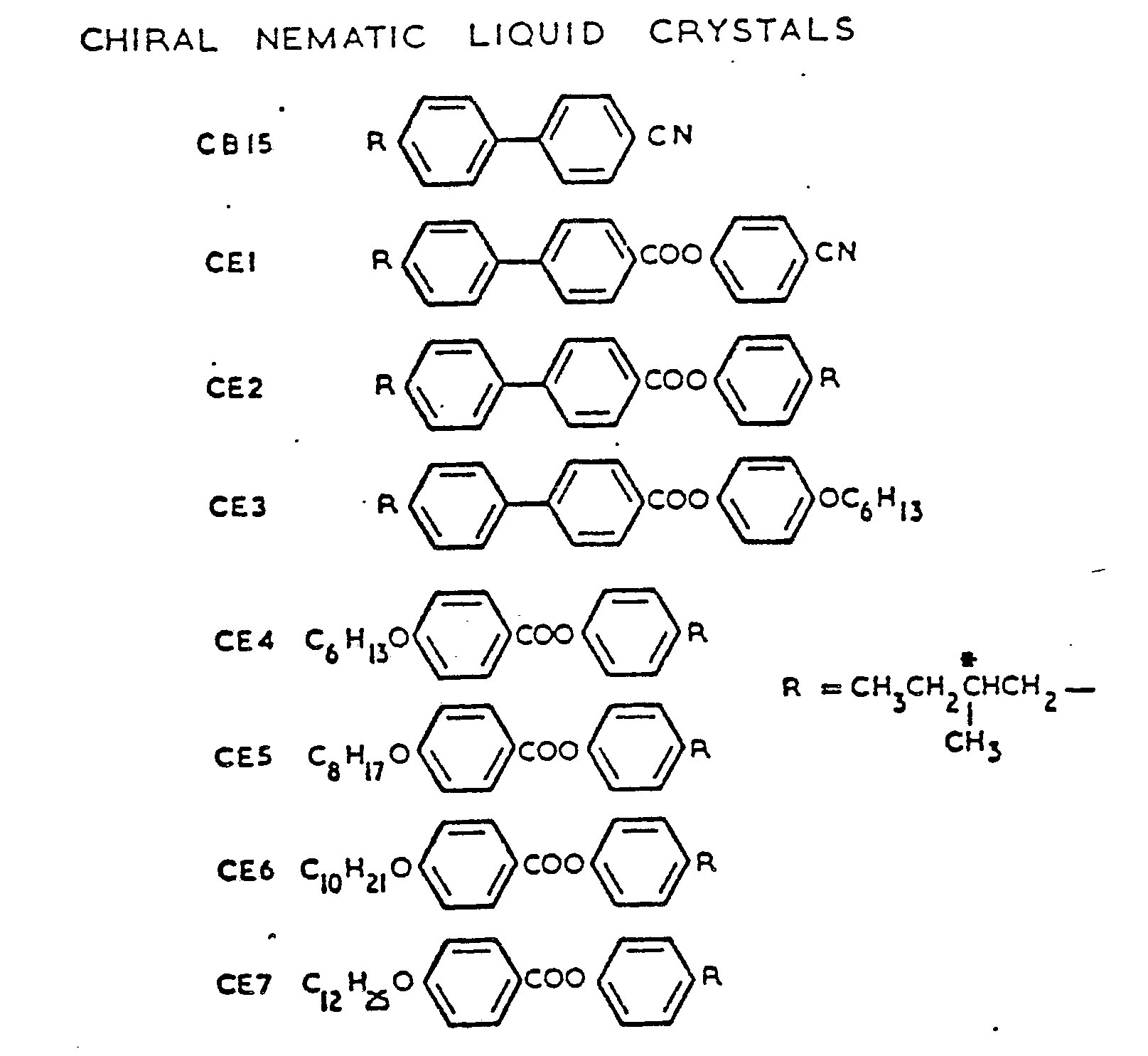
liquid crystal material 5 has a pitch, p, which selectively reflects visible light e.g. light between 380 and 780 nm wavelength. Examples of suitable materials are B.D.H. catalogue numbers TM 74A, TM 74B, TM 75A, and TM 75B. These are mixed to give a colour and a temperature range as required. One example is a mixture giving a colour play of red-blue over a temperature range of 21° to 25.5°C. This is formed of 40% by weight of mixture A + 60% by weight of mixture B. - Mixture A = 30% weight of TM 74A + 70% weight TM 75A.
- Mixture B = 30% weight of TM 74B + 70% weight TM 75B.
- A fine tuning of the range and colour may be made by adding small amounts of mixture A, B, TM 74A or TM 75B.
- Liquid crystal material is introduced between the walls by spreading a thin layer e.g. 10 µm thick over the profiled surface of one wall. The other wall is laid over the liquid crystal and the edges sealed e.g. by punching out shapes or pressure and temperature e.g. 100°C where required.
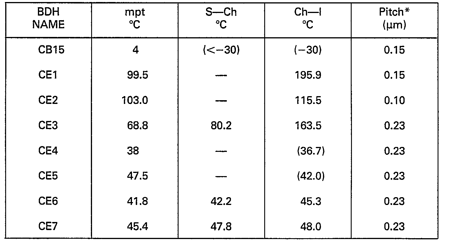
- Suitable materials for mixing are:
- The grating 7 may be formed on the Melinex® (I.C.I.) by embossing. A copper plate or roller is coated on a surface with a nickel plating. This plating is then selectively removed using standard photolithographic techniques to give a square or rectangular profile. Typically the grooves are 0.05 to 12 µm wide and 0.05-12 µm deep. The nickel layer is coated with a thin, less than 1 pm, layer of a release agent such as Fluorad Surfactant FC 721. The plate or roller is heated to about 105-115°C and pressed onto the amorphous surface layer of the Melinex 301 shet. A typical pressure is 3-5 atmospheres (2.9 x 10⁵-4.9 x 10⁵ Pa). This forms a fine grating on the Melinex 301.
- In operation white light is incident on the front wall of the cell. Coloured light e.g. red of one sense of circular polarisation is reflected back to an observer 8. The same red coloured light of the opposite sense of circular polarisation is transmitted through both
walls 2, 3 of the well to be absorbea. 6. Other wavelengths of light pass through the cell 1 and are absorbed by theabsorber 6. - The actual colour of reflected light is governed by the cholesteric pitch and refractive index, n
- As the temperature of the cholesteric changes pitch p changes and a different colour is observed. The amount and small range of frequencies reflected, i.e. colour purity, is enhanced by the accurate alignment of the cholesteric axis over the whole display.
- Figure 3 shows the surface profile of a cell 1 wall for use in larger displays. The
wall 3 is embossed to give both a grating 7, as in Figure 2, andpillars 9. These pillars help give a reasonably uniform thickness to the complete cell 1. Typically the pillars are of square section 25 pm x 25 pm, 25 pm high, and spaced 250-300 11m apart. Two sections of embossed Melinex may be brought into contact and quickly heated to fuse the pillars of one sheet onto the adjacent sheet. - The
cell walls 2, 3 may also be formed by thicker sheets of material, e.g. glass but in these cases the temperature changes are slower and the cell is not so flexible. - An alternative arrangement of display is shown in Figures 4 and 5. A thin
front wall 11 is embossed on its inner surface with a fine grating. For example a grating of square or sine wave profile with a pitch less than 5 pm e.g. a groove width of less than 2.5 µm, and with a groove depth of less than 0.1 pm. - The
rear wall 13 is embossed with acoarse profile 14. For example agroove 15 width of 100 pm, a groove depth of 10 µm to 50 pm, with a gap orweb 16 between grooves of 25 pm. The grooves in the front and rear walls may be arranged parallel or non-parallel e.g. orthogonal to one another. Anabsorber 6 covers the rear of the rear wall. - As seen in Figure 5 the coarse grating may have
grooves 15a extending the whole length of a sheet. Alternatively the grooves may havecross webs 17 to form elongated 15b or square 15c depressions in thewall 13 surface. These depressions may have rounded corners, and may be oval or even circular in plan. - To form a display cell liquid crystal material is spread over a
large sheet 13 having the coarse grating e.g. by silk screen printing, a roller, ink jet printing, or spraying to a depth of about 10 pm. Thefront wall 11, in the form of a large sheet, is placed over therear wall 13 and the two pressed together with an amount of heating e.g. to 100°C to seal the webs against the front wall. When the coarse grating hascross webs 17 the result is a plurality of closed cells. The complete display may then be cut with a knife or scissors into different shapes. - Different compositions of liquid crystal material may be printed in different areas of the rear wall. These different compositions may be separated by areas of non-liquid crystal material or be left empty.
- The bottom of the
groove 15 of the coarse grating may have superimposed thereon a fine grating. Alternatively the grooves may have homeotropic or homogeneous surface alignment treatment. - A memory effect may be provided by varying the profile of the grating 7, for example decreasing the depth and/or spacing of the grooves to reduce the aligning of liquid crystal molecules. Thus a change in molecular ordering caused by local heating is retained on cooling. Local deformation is needed to cause the display to return to its original state.
- One use for the display of this invention is for a thermal imaging system retina onto which an image of a thermal scene is focussed. A large number of very small display discs are mounted on a thin support of low lateral thermal conductivity. This separation of discs provides a reticulation and reduces lateral spread of the thermal image. Temperature variations across the retina are observed as different colours representing the thermal scene.
Claims (9)
Applications Claiming Priority (2)
| Application Number | Priority Date | Filing Date | Title |
|---|---|---|---|
| GB8318863 | 1983-07-12 | ||
| GB838318863A GB8318863D0 (en) | 1983-07-12 | 1983-07-12 | Thermochromic liquid crystal displays |
Publications (2)
| Publication Number | Publication Date |
|---|---|
| EP0132077A1 EP0132077A1 (en) | 1985-01-23 |
| EP0132077B1 true EP0132077B1 (en) | 1987-09-09 |
Family
ID=10545617
Family Applications (1)
| Application Number | Title | Priority Date | Filing Date |
|---|---|---|---|
| EP84304522A Expired EP0132077B1 (en) | 1983-07-12 | 1984-07-02 | Thermochromic liquid crystal displays |
Country Status (5)
| Country | Link |
|---|---|
| US (1) | US4834500A (en) |
| EP (1) | EP0132077B1 (en) |
| JP (1) | JPS6052890A (en) |
| DE (1) | DE3466085D1 (en) |
| GB (2) | GB8318863D0 (en) |
Families Citing this family (77)
| Publication number | Priority date | Publication date | Assignee | Title |
|---|---|---|---|---|
| JPS5531512A (en) * | 1978-08-16 | 1980-03-05 | Mitsubishi Electric Corp | Controlling method of spark machining |
| GB8515510D0 (en) * | 1985-06-19 | 1985-07-24 | Secr Defence | Thermochromic liquid crystal materials |
| US5299037A (en) * | 1985-08-07 | 1994-03-29 | Canon Kabushiki Kaisha | Diffraction grating type liquid crystal display device in viewfinder |
| GB2194351B (en) * | 1986-06-27 | 1989-12-20 | Gen Electric Plc | Thermal imaging device |
| GB8703306D0 (en) * | 1987-02-13 | 1987-03-18 | Ici Plc | Devices |
| US4952033A (en) * | 1987-07-13 | 1990-08-28 | James L. Fergason | Liquid crystal medical device |
| US5058999A (en) * | 1987-07-13 | 1991-10-22 | Frederick Davis | Liquid crystal device having distinguishing means |
| US5124819A (en) * | 1987-07-13 | 1992-06-23 | James L. Fergason | Liquid crystal medical device having distinguishing means |
| GB8804177D0 (en) * | 1988-02-23 | 1988-03-23 | Secr Defence | Surface temperature mapping using liquid crystal materials |
| EP0357844B1 (en) * | 1988-09-09 | 1993-05-12 | Akzo Nobel N.V. | Thermochromic effect coating |
| US5223958A (en) * | 1988-12-30 | 1993-06-29 | Hyperdesign, Inc. | Heat activated amusement device employing microencapsulated thermochromic liquid crystal |
| US5231528A (en) * | 1989-06-23 | 1993-07-27 | Hoechst Aktiengesellschaft | Ferroelectric liquid crystal components having high spontaneous polarization and low helical pitch |
| JP2682310B2 (en) * | 1991-12-02 | 1997-11-26 | 三菱電機株式会社 | Wire electric discharge machining method and apparatus |
| US5268782A (en) * | 1992-01-16 | 1993-12-07 | Minnesota Mining And Manufacturing Company | Micro-ridged, polymeric liquid crystal display substrate and display device |
| US5365356A (en) * | 1992-08-11 | 1994-11-15 | Minnesota Mining And Manufacturing Company | Method of fabricating an encapsulated liquid crystal display |
| US5441418A (en) * | 1993-05-20 | 1995-08-15 | Binney & Smith Inc. | Thermochromic drawing device |
| US5514635A (en) * | 1993-12-29 | 1996-05-07 | Optum Corporation | Thermal writing surface and method for making the same |
| US5717422A (en) * | 1994-01-25 | 1998-02-10 | Fergason; James L. | Variable intensity high contrast passive display |
| US5541745A (en) * | 1994-01-25 | 1996-07-30 | Fergason; James L. | Illumination system for a display using cholesteric liquid crystal reflectors |
| US5532854A (en) * | 1994-01-25 | 1996-07-02 | Fergason; James L. | Folded variable birefringerence zeroth order hybrid aligned liquid crystal apparatus |
| GB9402492D0 (en) * | 1994-02-09 | 1994-03-30 | Secr Defence | Liquid crystal device alignment |
| GB9402513D0 (en) * | 1994-02-09 | 1994-03-30 | Secr Defence | Bistable nematic liquid crystal device |
| US5401947A (en) * | 1994-03-15 | 1995-03-28 | Poland; Terrell A. | Information display and product identification system |
| US6184969B1 (en) * | 1994-10-25 | 2001-02-06 | James L. Fergason | Optical display system and method, active and passive dithering using birefringence, color image superpositioning and display enhancement |
| US5715029A (en) * | 1994-10-25 | 1998-02-03 | Fergason; James L. | Optical dithering system using birefringence for optical displays and method |
| US5537256A (en) * | 1994-10-25 | 1996-07-16 | Fergason; James L. | Electronic dithering system using birefrigence for optical displays and method |
| US5572341A (en) * | 1994-10-25 | 1996-11-05 | Fergason; James L. | Electro-optical dithering system using birefringence for optical displays and method |
| US6243055B1 (en) | 1994-10-25 | 2001-06-05 | James L. Fergason | Optical display system and method with optical shifting of pixel position including conversion of pixel layout to form delta to stripe pattern by time base multiplexing |
| CA2166847C (en) * | 1995-09-19 | 2000-09-05 | Frederick Davis | Multilayered dispersed thermochromic liquid crystal |
| SE515437C2 (en) * | 1997-10-22 | 2001-08-06 | Lars Andersson | Figure Painting |
| JP3773723B2 (en) * | 1999-01-29 | 2006-05-10 | シャープ株式会社 | Liquid crystal display |
| DE10101897A1 (en) * | 2001-01-16 | 2002-07-18 | Sunyx Gmbh | Device for monitoring temperatures comprises a container incorporating a surface that is both hydrophobic and oleophobic, and holding a liquid with a temperature dependent expansion coefficient |
| EP1381910A1 (en) * | 2001-04-24 | 2004-01-21 | MERCK PATENT GmbH | Liquid crystal device exhibiting optical properties which are changeable after assembly |
| US7064740B2 (en) * | 2001-11-09 | 2006-06-20 | Sharp Laboratories Of America, Inc. | Backlit display with improved dynamic range |
| EP2209027A1 (en) | 2002-02-13 | 2010-07-21 | MERCK PATENT GmbH | Security marking comprising an anisotropic polymer film on a substrate with a structured surface |
| DE60332784D1 (en) * | 2002-02-13 | 2010-07-15 | Merck Patent Gmbh | A method of making an anisotropic polymer film on a substrate having a structured surface |
| US8243004B2 (en) | 2003-03-10 | 2012-08-14 | Fergason Patent Properties, Llc | Apparatus and method for preparing, storing, transmitting and displaying images |
| WO2005052673A2 (en) | 2003-11-21 | 2005-06-09 | Sharp Laboratories Of America, Inc. | Liquid crystal display with adaptive color |
| JP4757201B2 (en) * | 2003-12-18 | 2011-08-24 | シャープ株式会社 | Dynamic gamma for liquid crystal displays |
| US8395577B2 (en) * | 2004-05-04 | 2013-03-12 | Sharp Laboratories Of America, Inc. | Liquid crystal display with illumination control |
| US20050248553A1 (en) * | 2004-05-04 | 2005-11-10 | Sharp Laboratories Of America, Inc. | Adaptive flicker and motion blur control |
| US7505018B2 (en) * | 2004-05-04 | 2009-03-17 | Sharp Laboratories Of America, Inc. | Liquid crystal display with reduced black level insertion |
| US7872631B2 (en) * | 2004-05-04 | 2011-01-18 | Sharp Laboratories Of America, Inc. | Liquid crystal display with temporal black point |
| US7777714B2 (en) * | 2004-05-04 | 2010-08-17 | Sharp Laboratories Of America, Inc. | Liquid crystal display with adaptive width |
| US7532192B2 (en) * | 2004-05-04 | 2009-05-12 | Sharp Laboratories Of America, Inc. | Liquid crystal display with filtered black point |
| US7612757B2 (en) * | 2004-05-04 | 2009-11-03 | Sharp Laboratories Of America, Inc. | Liquid crystal display with modulated black point |
| US7023451B2 (en) * | 2004-06-14 | 2006-04-04 | Sharp Laboratories Of America, Inc. | System for reducing crosstalk |
| US7556836B2 (en) * | 2004-09-03 | 2009-07-07 | Solae, Llc | High protein snack product |
| US7898519B2 (en) * | 2005-02-17 | 2011-03-01 | Sharp Laboratories Of America, Inc. | Method for overdriving a backlit display |
| US8050512B2 (en) | 2004-11-16 | 2011-11-01 | Sharp Laboratories Of America, Inc. | High dynamic range images from low dynamic range images |
| US7525528B2 (en) * | 2004-11-16 | 2009-04-28 | Sharp Laboratories Of America, Inc. | Technique that preserves specular highlights |
| US8050511B2 (en) * | 2004-11-16 | 2011-11-01 | Sharp Laboratories Of America, Inc. | High dynamic range images from low dynamic range images |
| US9143657B2 (en) * | 2006-01-24 | 2015-09-22 | Sharp Laboratories Of America, Inc. | Color enhancement technique using skin color detection |
| US8121401B2 (en) * | 2006-01-24 | 2012-02-21 | Sharp Labortories of America, Inc. | Method for reducing enhancement of artifacts and noise in image color enhancement |
| US8941580B2 (en) * | 2006-11-30 | 2015-01-27 | Sharp Laboratories Of America, Inc. | Liquid crystal display with area adaptive backlight |
| US20090108009A1 (en) | 2007-10-27 | 2009-04-30 | Sar Holdings International Limited | Silicone Baby Products |
| TW200941076A (en) * | 2008-03-31 | 2009-10-01 | Ind Tech Res Inst | Color cholesteric liquid crystal display devices and fabrication methods thereof |
| US20140274439A1 (en) | 2013-03-15 | 2014-09-18 | Sanwood Llc | Impact Indication and Data Tracking Devices and Methods |
| AU2015323940B2 (en) | 2014-09-29 | 2021-05-20 | Magic Leap, Inc. | Architectures and methods for outputting different wavelength light out of waveguides |
| KR102630754B1 (en) | 2015-03-16 | 2024-01-26 | 매직 립, 인코포레이티드 | Augmented Reality Pulse Oximetry |
| KR102449800B1 (en) | 2015-06-15 | 2022-09-29 | 매직 립, 인코포레이티드 | Virtual and augmented reality systems and methods |
| WO2017176898A1 (en) | 2016-04-08 | 2017-10-12 | Magic Leap, Inc. | Augmented reality systems and methods with variable focus lens elements |
| WO2017196999A1 (en) | 2016-05-12 | 2017-11-16 | Magic Leap, Inc. | Wavelength multiplexing in waveguides |
| US11067860B2 (en) | 2016-11-18 | 2021-07-20 | Magic Leap, Inc. | Liquid crystal diffractive devices with nano-scale pattern and methods of manufacturing the same |
| US10908423B2 (en) | 2016-11-18 | 2021-02-02 | Magic Leap, Inc. | Multilayer liquid crystal diffractive gratings for redirecting light of wide incident angle ranges |
| EP3542215B1 (en) | 2016-11-18 | 2022-11-02 | Magic Leap, Inc. | Spatially variable liquid crystal diffraction gratings |
| WO2018094093A1 (en) | 2016-11-18 | 2018-05-24 | Magic Leap, Inc. | Waveguide light multiplexer using crossed gratings |
| EP4002000B1 (en) | 2016-12-08 | 2025-02-19 | Magic Leap, Inc. | Diffractive devices based on cholesteric liquid crystal |
| KR102550742B1 (en) | 2016-12-14 | 2023-06-30 | 매직 립, 인코포레이티드 | Patterning of liquid crystals using soft-imprint replication of surface alignment patterns |
| CN110462460B (en) | 2017-01-23 | 2022-10-14 | 奇跃公司 | Eyepiece for virtual, augmented or mixed reality systems |
| KR102574219B1 (en) | 2017-02-23 | 2023-09-01 | 매직 립, 인코포레이티드 | Variable-focus virtual image devices based on polarization conversion |
| AU2018239264B2 (en) | 2017-03-21 | 2023-05-18 | Magic Leap, Inc. | Eye-imaging apparatus using diffractive optical elements |
| IL273397B2 (en) | 2017-09-21 | 2024-09-01 | Magic Leap Inc | Augmented reality display with waveguide configured to capture images of eye and/or environment |
| AU2018386296B2 (en) | 2017-12-15 | 2023-11-23 | Magic Leap, Inc. | Eyepieces for augmented reality display system |
| WO2020106824A1 (en) | 2018-11-20 | 2020-05-28 | Magic Leap, Inc. | Eyepieces for augmented reality display system |
| CN114286962A (en) | 2019-06-20 | 2022-04-05 | 奇跃公司 | Eyepiece for augmented reality display system |
| CN112040052B (en) * | 2020-08-12 | 2022-05-17 | 维沃移动通信有限公司 | A detection module and electronic equipment |
Family Cites Families (14)
| Publication number | Priority date | Publication date | Assignee | Title |
|---|---|---|---|---|
| US3533399A (en) * | 1965-08-02 | 1970-10-13 | Westinghouse Electric Corp | Temperature sensing means and methods |
| FR2189767B1 (en) * | 1972-06-23 | 1976-06-11 | Western Electric Co | |
| US3978580A (en) * | 1973-06-28 | 1976-09-07 | Hughes Aircraft Company | Method of fabricating a liquid crystal display |
| JPS5410501B2 (en) * | 1974-11-14 | 1979-05-07 | ||
| GB1571496A (en) * | 1976-05-04 | 1980-07-16 | Standard Telephones Cables Ltd | Cholesteric liquid crystal cells |
| AT369901B (en) * | 1976-06-25 | 1983-02-10 | Rupert Dipl Ing Dr Chabicovsky | METHOD FOR PRODUCING ELECTRODES FOR LIQUID CRYSTAL CELLS |
| US4140016A (en) * | 1977-04-07 | 1979-02-20 | Becton, Dickinson And Company | Novel compositions, devices and method |
| US4251137A (en) * | 1977-09-28 | 1981-02-17 | Rca Corporation | Tunable diffractive subtractive filter |
| US4256787A (en) * | 1978-05-03 | 1981-03-17 | Massachusetts Institute Of Technology | Orientation of ordered liquids and their use in devices |
| NL7808899A (en) * | 1978-08-30 | 1980-03-04 | Philips Nv | DISPLAY WITH LIQUID CRYSTAL. |
| US4388139A (en) * | 1980-07-14 | 1983-06-14 | Fuller David L | Thermosensing article and method of manufacture |
| US4398805A (en) * | 1981-07-06 | 1983-08-16 | General Electric Company | Transflective liquid crystal display |
| NL8200069A (en) * | 1982-01-11 | 1983-08-01 | Philips Nv | DISPLAY WITH LIQUID CRYSTAL. |
| JPS612130A (en) * | 1984-06-14 | 1986-01-08 | Sharp Corp | liquid crystal display element |
-
1983
- 1983-07-12 GB GB838318863A patent/GB8318863D0/en active Pending
-
1984
- 1984-07-02 EP EP84304522A patent/EP0132077B1/en not_active Expired
- 1984-07-02 DE DE8484304522T patent/DE3466085D1/en not_active Expired
- 1984-07-09 GB GB08417499A patent/GB2143323B/en not_active Expired
- 1984-07-10 JP JP59143175A patent/JPS6052890A/en active Granted
-
1987
- 1987-02-19 US US07/016,621 patent/US4834500A/en not_active Expired - Fee Related
Also Published As
| Publication number | Publication date |
|---|---|
| GB2143323A (en) | 1985-02-06 |
| EP0132077A1 (en) | 1985-01-23 |
| GB2143323B (en) | 1987-03-25 |
| JPS6052890A (en) | 1985-03-26 |
| GB8318863D0 (en) | 1983-08-10 |
| US4834500A (en) | 1989-05-30 |
| GB8417499D0 (en) | 1984-08-15 |
| DE3466085D1 (en) | 1987-10-15 |
| JPH0564358B2 (en) | 1993-09-14 |
Similar Documents
| Publication | Publication Date | Title |
|---|---|---|
| EP0132077B1 (en) | Thermochromic liquid crystal displays | |
| EP0908745B1 (en) | Lighting device and liquid crystal display | |
| KR100502208B1 (en) | Liquid crystal display device for forming a color image display screen | |
| US5148302A (en) | Optical modulation element having two-dimensional phase type diffraction grating | |
| US4606611A (en) | Enhanced scattering in voltage sensitive encapsulated liquid crystal | |
| US4729640A (en) | Liquid crystal light modulation device | |
| CA1262485A (en) | Encapsulated liquid crystal material, apparatus and method | |
| DE69209534T2 (en) | Reflective liquid crystal display device and method of manufacturing the same | |
| EP2159610B1 (en) | Optical element, display device, and optical device | |
| EP0351200B1 (en) | Liquid crystal display apparatus | |
| KR930006492A (en) | Liquid crystal display | |
| US6906764B2 (en) | Reflective cholesteric filter | |
| CN102713726B (en) | Adhesive film for orientation treatment of photo-alignment film | |
| US4810063A (en) | Enhanced scattering voltage sensitive encapsulated liquid crystal with light directing and interference layer features | |
| JP6268941B2 (en) | Device for preventing forgery and method for manufacturing the same | |
| GB2052779A (en) | Liquid Crystal Display Cell | |
| EP1780582A1 (en) | Polarized diffractive filter and layered polarized diffractive filter | |
| US6130738A (en) | Liquid crystal device having a resin wall using different resins with different surface interactions structure and manufacturing method for same | |
| Kishino et al. | Wideband reflection wavelength tuning by bending of cholesteric liquid crystal elastomer films | |
| EP0278721A2 (en) | Electro-optical devices and methods for making them | |
| EP0023421A1 (en) | Liquid crystal display device | |
| WO2005116735A1 (en) | Reflective liquid crystal display with infrared reflection | |
| US4844596A (en) | Aligning and distorting features in enhanced scattering voltage sensitive encapsulated liquid crystal | |
| KR20030085517A (en) | Twisted nematic micropolarizer and its method of manufacturing | |
| Date et al. | Droplet size effect on the memory-mode operating temperature of smectic-A holographic polymer dispersed liquid crystal |
Legal Events
| Date | Code | Title | Description |
|---|---|---|---|
| PUAI | Public reference made under article 153(3) epc to a published international application that has entered the european phase |
Free format text: ORIGINAL CODE: 0009012 |
|
| AK | Designated contracting states |
Designated state(s): DE FR IT |
|
| 17P | Request for examination filed |
Effective date: 19850604 |
|
| 17Q | First examination report despatched |
Effective date: 19861031 |
|
| ITF | It: translation for a ep patent filed | ||
| GRAA | (expected) grant |
Free format text: ORIGINAL CODE: 0009210 |
|
| AK | Designated contracting states |
Kind code of ref document: B1 Designated state(s): DE FR IT |
|
| ET | Fr: translation filed | ||
| REF | Corresponds to: |
Ref document number: 3466085 Country of ref document: DE Date of ref document: 19871015 |
|
| PLBE | No opposition filed within time limit |
Free format text: ORIGINAL CODE: 0009261 |
|
| STAA | Information on the status of an ep patent application or granted ep patent |
Free format text: STATUS: NO OPPOSITION FILED WITHIN TIME LIMIT |
|
| 26N | No opposition filed | ||
| ITTA | It: last paid annual fee | ||
| PGFP | Annual fee paid to national office [announced via postgrant information from national office to epo] |
Ref country code: FR Payment date: 19990615 Year of fee payment: 16 |
|
| PGFP | Annual fee paid to national office [announced via postgrant information from national office to epo] |
Ref country code: DE Payment date: 19990628 Year of fee payment: 16 |
|
| PG25 | Lapsed in a contracting state [announced via postgrant information from national office to epo] |
Ref country code: FR Free format text: LAPSE BECAUSE OF NON-PAYMENT OF DUE FEES Effective date: 20010330 |
|
| REG | Reference to a national code |
Ref country code: FR Ref legal event code: ST |
|
| PG25 | Lapsed in a contracting state [announced via postgrant information from national office to epo] |
Ref country code: DE Free format text: LAPSE BECAUSE OF NON-PAYMENT OF DUE FEES Effective date: 20010501 |