EP0060203A2 - Tenon-and-mortise type connection, and furniture incorporating the same - Google Patents
Tenon-and-mortise type connection, and furniture incorporating the same Download PDFInfo
- Publication number
- EP0060203A2 EP0060203A2 EP82400426A EP82400426A EP0060203A2 EP 0060203 A2 EP0060203 A2 EP 0060203A2 EP 82400426 A EP82400426 A EP 82400426A EP 82400426 A EP82400426 A EP 82400426A EP 0060203 A2 EP0060203 A2 EP 0060203A2
- Authority
- EP
- European Patent Office
- Prior art keywords
- mortise
- tenon
- assembled
- assembly
- housing
- Prior art date
- Legal status (The legal status is an assumption and is not a legal conclusion. Google has not performed a legal analysis and makes no representation as to the accuracy of the status listed.)
- Withdrawn
Links
- 239000002023 wood Substances 0.000 claims description 4
- 230000000295 complement effect Effects 0.000 claims description 3
- 230000004308 accommodation Effects 0.000 claims description 2
- 230000021615 conjugation Effects 0.000 claims description 2
- 230000000712 assembly Effects 0.000 description 5
- 238000000429 assembly Methods 0.000 description 5
- 239000002184 metal Substances 0.000 description 5
- CNQCVBJFEGMYDW-UHFFFAOYSA-N lawrencium atom Chemical compound [Lr] CNQCVBJFEGMYDW-UHFFFAOYSA-N 0.000 description 3
- 239000000463 material Substances 0.000 description 2
- 238000005553 drilling Methods 0.000 description 1
Images


Classifications
-
- F—MECHANICAL ENGINEERING; LIGHTING; HEATING; WEAPONS; BLASTING
- F16—ENGINEERING ELEMENTS AND UNITS; GENERAL MEASURES FOR PRODUCING AND MAINTAINING EFFECTIVE FUNCTIONING OF MACHINES OR INSTALLATIONS; THERMAL INSULATION IN GENERAL
- F16B—DEVICES FOR FASTENING OR SECURING CONSTRUCTIONAL ELEMENTS OR MACHINE PARTS TOGETHER, e.g. NAILS, BOLTS, CIRCLIPS, CLAMPS, CLIPS OR WEDGES; JOINTS OR JOINTING
- F16B12/00—Jointing of furniture or the like, e.g. hidden from exterior
- F16B12/10—Jointing of furniture or the like, e.g. hidden from exterior using pegs, bolts, tenons, clamps, clips, or the like
- F16B12/12—Jointing of furniture or the like, e.g. hidden from exterior using pegs, bolts, tenons, clamps, clips, or the like for non-metal furniture parts, e.g. made of wood, of plastics
- F16B12/125—Jointing of furniture or the like, e.g. hidden from exterior using pegs, bolts, tenons, clamps, clips, or the like for non-metal furniture parts, e.g. made of wood, of plastics using mortise and tenon joints
-
- F—MECHANICAL ENGINEERING; LIGHTING; HEATING; WEAPONS; BLASTING
- F16—ENGINEERING ELEMENTS AND UNITS; GENERAL MEASURES FOR PRODUCING AND MAINTAINING EFFECTIVE FUNCTIONING OF MACHINES OR INSTALLATIONS; THERMAL INSULATION IN GENERAL
- F16B—DEVICES FOR FASTENING OR SECURING CONSTRUCTIONAL ELEMENTS OR MACHINE PARTS TOGETHER, e.g. NAILS, BOLTS, CIRCLIPS, CLAMPS, CLIPS OR WEDGES; JOINTS OR JOINTING
- F16B12/00—Jointing of furniture or the like, e.g. hidden from exterior
- F16B12/10—Jointing of furniture or the like, e.g. hidden from exterior using pegs, bolts, tenons, clamps, clips, or the like
- F16B12/12—Jointing of furniture or the like, e.g. hidden from exterior using pegs, bolts, tenons, clamps, clips, or the like for non-metal furniture parts, e.g. made of wood, of plastics
- F16B12/24—Jointing of furniture or the like, e.g. hidden from exterior using pegs, bolts, tenons, clamps, clips, or the like for non-metal furniture parts, e.g. made of wood, of plastics using separate pins, dowels, or the like
-
- Y—GENERAL TAGGING OF NEW TECHNOLOGICAL DEVELOPMENTS; GENERAL TAGGING OF CROSS-SECTIONAL TECHNOLOGIES SPANNING OVER SEVERAL SECTIONS OF THE IPC; TECHNICAL SUBJECTS COVERED BY FORMER USPC CROSS-REFERENCE ART COLLECTIONS [XRACs] AND DIGESTS
- Y10—TECHNICAL SUBJECTS COVERED BY FORMER USPC
- Y10T—TECHNICAL SUBJECTS COVERED BY FORMER US CLASSIFICATION
- Y10T403/00—Joints and connections
- Y10T403/44—Three or more members connected at single locus
-
- Y—GENERAL TAGGING OF NEW TECHNOLOGICAL DEVELOPMENTS; GENERAL TAGGING OF CROSS-SECTIONAL TECHNOLOGIES SPANNING OVER SEVERAL SECTIONS OF THE IPC; TECHNICAL SUBJECTS COVERED BY FORMER USPC CROSS-REFERENCE ART COLLECTIONS [XRACs] AND DIGESTS
- Y10—TECHNICAL SUBJECTS COVERED BY FORMER USPC
- Y10T—TECHNICAL SUBJECTS COVERED BY FORMER US CLASSIFICATION
- Y10T403/00—Joints and connections
- Y10T403/55—Member ends joined by inserted section
- Y10T403/551—Externally bridged
-
- Y—GENERAL TAGGING OF NEW TECHNOLOGICAL DEVELOPMENTS; GENERAL TAGGING OF CROSS-SECTIONAL TECHNOLOGIES SPANNING OVER SEVERAL SECTIONS OF THE IPC; TECHNICAL SUBJECTS COVERED BY FORMER USPC CROSS-REFERENCE ART COLLECTIONS [XRACs] AND DIGESTS
- Y10—TECHNICAL SUBJECTS COVERED BY FORMER USPC
- Y10T—TECHNICAL SUBJECTS COVERED BY FORMER US CLASSIFICATION
- Y10T403/00—Joints and connections
- Y10T403/70—Interfitted members
- Y10T403/7075—Interfitted members including discrete retainer
- Y10T403/7077—Interfitted members including discrete retainer for telescoping members
- Y10T403/7079—Transverse pin
- Y10T403/7084—Bolt, rivet, or screw
Definitions
- the invention relates to the field of assembly systems of the tenon and mortise type. It is most advantageously applicable for assembling wooden elements, for example for making furniture of all kinds, in particular shelves, cupboards, etc. It goes without saying, however, that the invention can be used with elements made of materials other than wood, in particular metallic or plastic elements.
- Assembly systems of the tenon and mortise type are well known in the art. They have been widely used in the wood industry, in particular. It is important, however, to find improvements to this basic system, in order to produce precision assemblies as well as to allow arrangements of elements arranged in various planes. It is for example desirable to produce assemblies in three dimensions.
- the subject of the invention is such an assembly system which makes it possible to mount elements with great precision and security, even in several planes orthogonal to each other.
- the invention in its general form, relates to an assembly system of the tenon and mortise type, characterized in that it essentially comprises a mortise or sheath, produced in a first element to be assembled and comprising at least one housing and at least a pair of studs, the two studs of a pair being provided respectively on two other elements to be assembled, the number of pairs of studs corresponding to that of said housings, each of the studs cooperating by conjugation in form with a housing, the arrangement being such that when assembling the two studs of a pair of studs say pose vis-à-vis with their contact surface inside the housing, the volume of a pair of pins assembled being substantially equal to the interior volume of the corresponding housing.
- the shape of the housing (s) can be any: cylindrical or prismatic.
- the section of the housing (s) can be a curve, advantageously a circle, or a polygon or a mixed line comprising arcs, preferably circular and straight segments.
- the shape of the tenons must correspond to that of the housing, into which they are introduced for the purpose of assembly.
- the two studs provided respectively on the other two elements to be assembled are inserted in a housing of the mortise so that the end faces of the two studs come into contact inside the housing.
- the pins are then themselves cylindrical and the end faces of the two pins abut one against the other, their contact surface then being contained in a plane perpendicular to the axis of the housing or oblique to it.
- the assembly system comprises a mortise with a housing, of parallelepiped shape, produced in a first element to be assembled and two tenons produced respectively on two other elements to be assembled, each tenon having the shape of a prism with a base consisting of a rectangular trapezoid, the slope of the trapezoidal faces of each tenon being equal and in the same direction, the assembly being such that the two tenons, the respective volume of which is substantially equal to half the useful volume of the mortise, are engaged in the latter on either side of the mortise, so that their respective trapezoidal faces come into application one against the other.
- each tenon is provided with a transverse bore, that the mortise has two holes coinciding respectively with the bores of the two tenons when the assembly is finished, that each additional element to be assembled has two orifices, an orifice being located in alignment with a hole in the mortise and the corresponding tenon drilling, thus constituting a transverse passage, and that connecting means are housed in each of said transverse passages o
- the connecting means comprise a threaded rod cooperating with a complementary thread insert disposed in each transverse bore of a tenon.
- the connecting means may consist simply of a threaded rod passing right through the transverse passage and comprising an end bolt.
- the two tenons of a pair come to nest in the mortise without there being any play in the assembly, especially when they have a rectangular trapezoid shape.
- the two tenons are engaged head to tail in the mortise, on both sides of it. We thus obtain, in a simple way, a very safe mounting and a precise assembly of the elements.
- Element 1 has a mortise 2 of parallelepiped shape (in this particular example the section is rectangular). At the mortise 2, two transverse holes 2a, 2b are made passing right through the element 1.
- the element 3 and the element 6 respectively comprise two tenons 4 and 7.
- the volume of each of these tenons is substantially equal to half the useful volume of the mortise 2.
- the shape of the tenons 4 and 7 constitutes an advantageous characteristic of the invention.
- the posts have a prismatic shape with a base consisting of a rectangular trapezoid.
- the trapezoidal faces 5 and 8 have equal slopes and in the same direction.
- the post 4 has a bore 4b which, in the example chosen, is established for wear a threaded metal insert.
- the post 7 has a bore 7a provided with a threaded insert.
- the mounting of elements 3 and 6 on element 1 is carried out, in accordance with the invention, by engaging in the mortise 2 the respective tenons 4 and 7 of elements 3 and 6.
- the arrangement is such that the trapezoidal faces 5 and 8 are applied one against the other, being housed in the useful volume of the mortise 2.
- the holes 2a and 2b of the mortise come exactly opposite the holes 7a and 4b of elements 3 and 6.
- FIG. 1 there is illustrated the mounting not only of elements 3 and 6 on element 1, but also of elements 9 and 10 which are arranged in a plane perpendicular to the mean plane of element 1
- the element 9 has two holes, 9a and 9b, while the element 10 has two corresponding holes 10a and 10b.
- the connecting means which are necessary for assembly.
- the rod 11 passes through the orifice 9a of the element 9 and the hole 2a of the mortise 2, before cooperating by screwing with the insert housed in the bore 7a of the tenon 7 of the element 6.
- the threaded rod 12 passes through the orifice 10b and the hole 2b to screw into the insert housed in the hole 4b.
- Figure 2 is a perspective view showing the elements 1, 3, 6, 9 and 10 in the assembly position.
- FIGS 3 and 4 illustrate the application of the assembly system according to the invention, for the production of furniture, for example shelves.
- an element 21 is assembled on the one hand with two pairs of elements 23, 33, and 26, 36, and, on the other hand, with two elements 29 and 30 in the form of shelves.
- the element 21 comprises two mortises 22, 32 provided with respective holes 22a, 22b and 32a, 32b.
- the elements 23 and 33 each comprising a tenon, produced in the manner described and illustrated above with reference to FIGS. 1 and 2.
- the element 23 comprises a trapezoidal tenon 24, intended to be housed in the mortise 22.
- the element 33 comprises a trapezoidal pin 34, intended to be housed in the mortise 32.
- the pins 24 and 34 are provided with threaded inserts 24b and 34b respectively.
- the elements 23 and 33 have tenons 34 ′, 35 ′ at the other end, advantageously identical to the tenons 24 and 34.
- the configuration of the elements 26 and 36 is similar to that of the elements 23 and 33. They have at one end tenons 27, 37, having respective inserts 27a, 37a. At their other end, they have studs 27 ', 37'.
- the trapezoidal surfaces 25 of the tenon 24 and 28 of the tenon 27, come opposite, apply one against the other inside the mortise 22. This is even for the trapezoidal surfaces 35 of the tenon 34 and 38 of the tenon 37, which are applied inside the mortise 32.
- the insert 24b comes exactly in alignment with the hole 22a
- the insert 27a comes in alignment with hole 22b
- insert 37a lines up with hole 32a
- insert 34b lines up with hole 32b.
- the element 29 comprises for example orifices 29a, 29b, intended to constitute a transverse passage with the holes 22a, 22b of the mortise 22. Opposite, the orifices 30a, 30b, of the element 30, are place in correspondence and alignment.
- the connecting means are threaded rods 40 and 50 which are respectively housed in the inserts provided in the corresponding studs.
- FIGS. 1 and 2 have been shown by making the face of the elements 9, 10 visible, which is normally hidden during assembly. It is the same for elements 29 and 30 of FIGS. 3 and 4. It will in fact be noted that during the production of an item of furniture, the connecting means are preferably hidden by the corresponding elements, such as the elements 9, 10, and 29.30.
- FIG. 5 illustrates in exploded perspective, in the same manner as Figure 1, an alternative embodiment of the assembly system according to the invention.
- the mortise provided in the element 101 comprises two housings 102, 102 '.
- these housings are cylindrical and their section is circular. It goes without saying that any other form or section would also be suitable.
- Each housing 102, 102 ' is provided with transverse holes 102b, 102a, passing right through the element 101.
- the element 103 comprises tenons 104 and 104 'of cylindrical shape corresponding to that of the housings 102 and 102'.
- the pin 104 has a bore 104b which can receive a threaded metal insert.
- the element 106 has pins 107 and 107 'of cylindrical shape, corresponding to that of the housings 102 and 102'.
- the pin 107 ' has a hole 107a which can receive a threaded metal insert.
- the pins 104 and 107 engage in the housing 102 and their faces 105 and 108 come into contact inside the housing 102.
- the total volume of the pins 104 and 107 corresponds substantially to the interior volume of the housing 102.
- the bore 104b of the tenonl04 comes to the alignment of the hole 102b.
- the pins 104 'and 107' engage in the housing 102 'and their faces 105' and 108 'come into contact inside the housing 102'.
- the total volume of the tenons 104 'and 107' corresponds substantially to the interior volume of the lodge ment 102 '.
- FIG. 5 also shows two elements 109 and 110 to illustrate an assembly in two orthogonal planes.
- the element 109 has two orifices 109a and 109b while the element 110 has two orifices 110a and 110b.
- threaded rods 111 and 112 which are representative of the connecting means necessary for assembly.
- the rod 111 passes through the orifice 109a of the element 109 and the hole 102a of the housing 102 ', before cooperating by screwing with the insert housed in the bore 107a of the tenon 107' of the element 106.
- the threaded rod2 passes through the hole 110b and the hole 102b to be screwed into the insert housed in the bore 104b of the tenon 104 of the element 103.
- the invention offers a general assembly system, which allows the production of a wide variety of furniture items. It is naturally advantageous that the design is modular, that is to say that the manufacturer has elements of dimensions determined in advance.
Landscapes
- Engineering & Computer Science (AREA)
- General Engineering & Computer Science (AREA)
- Mechanical Engineering (AREA)
- Furniture Connections (AREA)
- Assembled Shelves (AREA)
- Mutual Connection Of Rods And Tubes (AREA)
Abstract
Nouveau système d'assemblage du genre à tenon et mortaise et articles mobiliers incorporant ledit système. Il comprend essentiellement une mortaise ou fourreau (2) de forme parallélépipédique, réalisée dans un premier élément (1) à assembler, et deux tenons (4,7) réalisés respectivement sur deux autres éléments (3,6) à assembler, chaque tenon (4,7) ayant la forme d'un prisme avec une base constituée d'un trapèze rectangle, la pente des faces trapézoïdales (5,8) de chaque tenon étant égale et de même sens. Chaque tenon (4,7) est muni d'un perçage transversal (4b, 7a). La mortaise (2) comporte deux trous (2a, 2b) coïncidant respectivement avec les perçages (7a, 7b) des deux tenons (7,4) lorsque l'assemblage est terminé. Chaque élément supplémentaire (9, 10) à assembler présente deux orifices (9a, 9b; 10a, 10b). Des moyens (11, 12) assurent la liaison du système.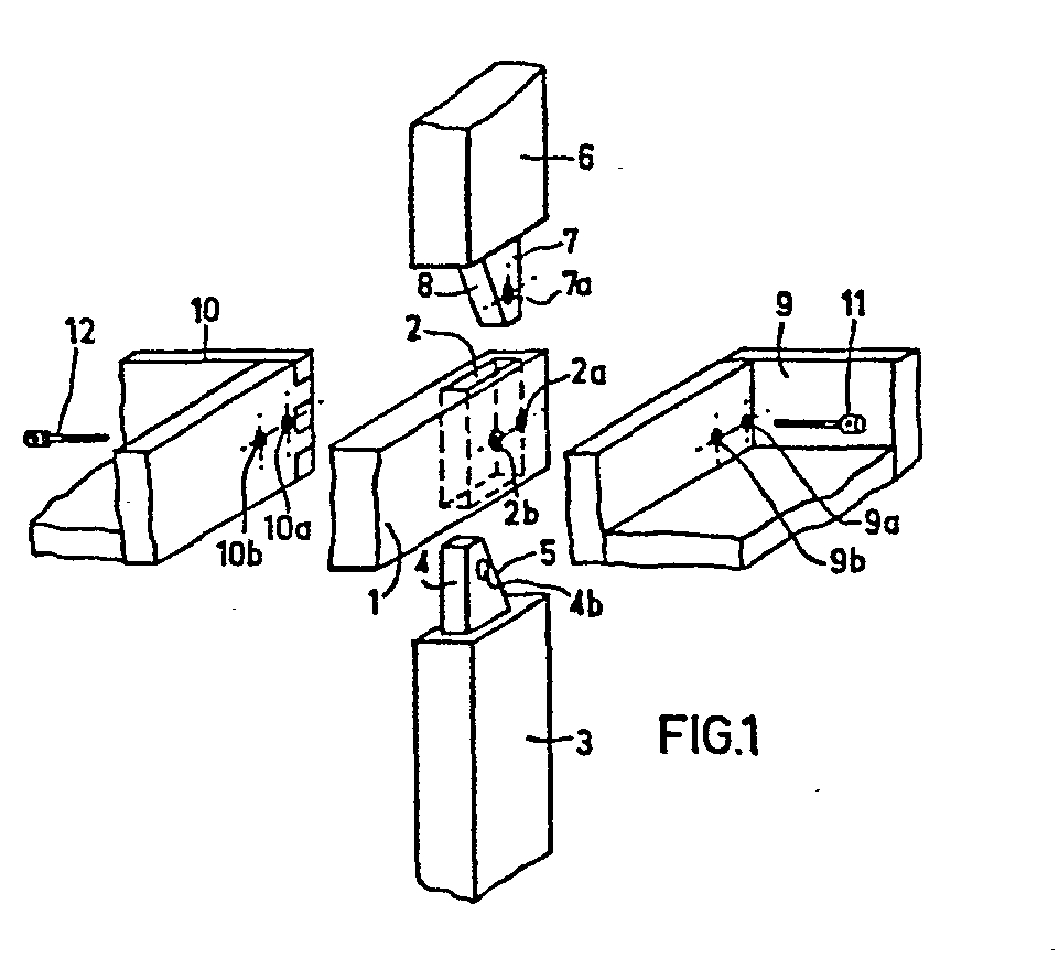
Description
L'invention concerne le domaine des systèmes d'- assemblage du genre à tenon et mortaise. Elle est applicable le plus avantageusement pour assembler des éléments en bois, par exemple pour réaliser des articles mobiliers de tout genre, notamment des étagères, des armoires, etc.... Il va sans dire, cependant, que l'invention est utilisable avec des éléments constitués de matières autres que le bois, en particulier des éléments métalliques ou en matière plastique.The invention relates to the field of assembly systems of the tenon and mortise type. It is most advantageously applicable for assembling wooden elements, for example for making furniture of all kinds, in particular shelves, cupboards, etc. It goes without saying, however, that the invention can be used with elements made of materials other than wood, in particular metallic or plastic elements.
Les systèmes d'assemblage du genre à tenon et mortaise sont bien connus de la technique. Ils ont été largement utilisés dans le domaine du bois, notamment. Il importe, cependant, de trouver des améliorations à ce système de base, en vue de réaliser des montages de précision ainsi que de permettre des agencements d'éléments disposés dans divers plans. Il est par exemple souhaitable de réaliser des assemblages en trois dimensions.Assembly systems of the tenon and mortise type are well known in the art. They have been widely used in the wood industry, in particular. It is important, however, to find improvements to this basic system, in order to produce precision assemblies as well as to allow arrangements of elements arranged in various planes. It is for example desirable to produce assemblies in three dimensions.
L'invention a pour objet un tel système d'assemblage qui permet de monter des éléments avec beaucoup de précision et de sécurité, même dans plusieurs plans orthogonaux entre eux.The subject of the invention is such an assembly system which makes it possible to mount elements with great precision and security, even in several planes orthogonal to each other.
Sous sa forme générale, l'invention concerne un système d'assemblage du genre à tenon et mortaise, caractérisé en ce qu'il comprend essentiellement une mortaise ou fourreau,réalisée dans un premier élément à assembler et comprenant au moins un logement et au moins une paire de tenons, les deux tenons d'une paire étant prévus respectivement sur deux autres éléments à assembler, le nombre de paires de tenons correspondant à celui desdits logements, chacun des tenons coopérant par conjugaison de forme avec un logement, la disposition étant telle qu'à l'assemblage les deux tenons d'une paire de tenons se disposent en vis-à-vis avec leur surface de contact à l'- intérieur du logement, le volume d'une paire de tenons assemblés étant sensiblement égal au volume intérieur du logement correspondant.In its general form, the invention relates to an assembly system of the tenon and mortise type, characterized in that it essentially comprises a mortise or sheath, produced in a first element to be assembled and comprising at least one housing and at least a pair of studs, the two studs of a pair being provided respectively on two other elements to be assembled, the number of pairs of studs corresponding to that of said housings, each of the studs cooperating by conjugation in form with a housing, the arrangement being such that when assembling the two studs of a pair of studs say pose vis-à-vis with their contact surface inside the housing, the volume of a pair of pins assembled being substantially equal to the interior volume of the corresponding housing.
Pour les besoins pratiques, il est le plus souvent suffisant de prévoir une mortaise comprenant un ou deux logements.For practical purposes, it is most often sufficient to provide a mortise comprising one or two dwellings.
La forme du ou des logements peut être quelconque : cylindrique ou prismatique. Ainsi la section du ou des logements peut être une courbe, avantageusement un cercle, ou un polygone ou une ligne mixte comprenant des arcs, de préférence circulaires et des segments de droite. Bien entendu la forme des tenons doit correspondre à celle dulogement, dans lequel ils sont introduits en vue de l'assemblage.The shape of the housing (s) can be any: cylindrical or prismatic. Thus, the section of the housing (s) can be a curve, advantageously a circle, or a polygon or a mixed line comprising arcs, preferably circular and straight segments. Of course, the shape of the tenons must correspond to that of the housing, into which they are introduced for the purpose of assembly.
Les deux tenons prévus respectivement sur les deux autres éléments à assembler s'insérent dans un logement de la mortaise de manière que les faces extrêmes des deux tenons viennent en contact à l'intérieur du logement.The two studs provided respectively on the other two elements to be assembled are inserted in a housing of the mortise so that the end faces of the two studs come into contact inside the housing.
Si le logement est cylindrique, les tenons sont alors eux-mêmes cylindriques et les faces extrêmes des deux tenons viennent en butée l'une contre l'autre, leur surface de contact étant alors contenue dans un plan perpendiculaire à l'axe du logement ou oblique par rapport à celui-ci.If the housing is cylindrical, the pins are then themselves cylindrical and the end faces of the two pins abut one against the other, their contact surface then being contained in a plane perpendicular to the axis of the housing or oblique to it.
Selon une forme préférée de réalisation, le système d'assemblage selon l'invention comprend une mortaise à un logement, de forme parallélépipédique, réalisée dans un premier élément à assembler et deux tenons réalisés respectivement sur deux autres éléments à assembler, chaque tenon ayant la forme d'un prisme avec une base constituée d'un trapèze rectangle, la pente des faces trapézoïdales de chaque tenon étant égale et de même sens, l'assemblage étant tel que les deux tenons, dont le volume respectif est sensiblement égal à la moitié du volume utile de la mortaise, sont engagés dans celle-ci de part et d'autre de la mortaise, de manière que leurs faces trapézoïdales respectives viennent en application l'une contre l'autre.According to a preferred embodiment, the assembly system according to the invention comprises a mortise with a housing, of parallelepiped shape, produced in a first element to be assembled and two tenons produced respectively on two other elements to be assembled, each tenon having the shape of a prism with a base consisting of a rectangular trapezoid, the slope of the trapezoidal faces of each tenon being equal and in the same direction, the assembly being such that the two tenons, the respective volume of which is substantially equal to half the useful volume of the mortise, are engaged in the latter on either side of the mortise, so that their respective trapezoidal faces come into application one against the other.
Si, comme il est fréquent, on souhaite adjoindre à l'assemblage des éléments supplémentaires disposés dans un plan perpendiculaire au plan moyen de la mortaise, l'invention prévoit que chaque tenon est muni d'un perçage transversal, que la mortaise comporte deux trous coïncidant respectivement avec les perçages des deux tenons lorsque l'assemblage est terminé, que chaque élément supplémentaire à assembler présente deux orifices, un orifice étant situé dans l'alignement d'un trou de la mortaise et du perçage du tenon correspondant, en constituant ainsi un passage transversal, et que des moyens de liaison sont logés dans chacun desdits passages transversauxo If, as is frequent, it is desired to add to the assembly additional elements arranged in a plane perpendicular to the mean plane of the mortise, the invention provides that each tenon is provided with a transverse bore, that the mortise has two holes coinciding respectively with the bores of the two tenons when the assembly is finished, that each additional element to be assembled has two orifices, an orifice being located in alignment with a hole in the mortise and the corresponding tenon drilling, thus constituting a transverse passage, and that connecting means are housed in each of said transverse passages o
Dans une forme préférée de réalisation, les moyens de liaison comprennent une tige filetée coopérant avec un insert de filetage complémentaire disposé dans chaque perçage transversal d'un tenon.In a preferred embodiment, the connecting means comprise a threaded rod cooperating with a complementary thread insert disposed in each transverse bore of a tenon.
En variante, dans le cas où l'utilisation d'un insert dans les tenons n'est pas nécessaire, les moyens de liaison peuvent consister simplement en une tige filetée traversant de part en part le passage transversal et comportant un boulon d'extrémité.Alternatively, in the case where the use of an insert in the studs is not necessary, the connecting means may consist simply of a threaded rod passing right through the transverse passage and comprising an end bolt.
Selon la caractéristique essentielle de l'invention, les deux tenons d'une paire viennent s'imbriquer dans la mortaise sans qu'il yait de jeu à l'assemblage, surtout lorsqu'ils ont une forme en trapèze rectangle. Les deux tenons sont engagés tête-bêche dans la mortaise, de part et d'autre de celle-ci. On obtient ainsi, de façon simple, un montage très sûr et un assemblage précis des éléments.According to the essential characteristic of the invention, the two tenons of a pair come to nest in the mortise without there being any play in the assembly, especially when they have a rectangular trapezoid shape. The two tenons are engaged head to tail in the mortise, on both sides of it. We thus obtain, in a simple way, a very safe mounting and a precise assembly of the elements.
L'invention sera maintenant illustrée sans être aucunement limitée, par la description ci-après de certains exemples de réalisation, en référence aux dessins annexés sur lesquels :
- Fig. 1 est une vue éclatée en perspective montrant le système avant assemblage.
- Fig. 2 est une vue correspondant à la figure 1, montrant les éléments assemblés.
- Fig. 3 est une vue en perspective éclatée, montrant une application du système d'assemblage selon les figures 1 et 2 pour la réalisation d'articles mobiliers.
- Fig. 4 est une vue correspondant à la figure 3, montrant les éléments du système assemblés.
- Fig. 5 est une vue en perspective éclatée d'une variante du système d'assemblage.
- Fig. 1 is an exploded perspective view showing the system before assembly.
- Fig. 2 is a view corresponding to FIG. 1, showing the assembled elements.
- Fig. 3 is an exploded perspective view showing an application of the assembly system according to Figures 1 and 2 for the production of furniture articles.
- Fig. 4 is a view corresponding to FIG. 3, showing the elements of the system assembled.
- Fig. 5 is an exploded perspective view of a variant of the assembly system.
Dans la forme de réalisation représentée aux figures 1 et 2,les éléments à assembler sont désignés par les références 1, 3, 6, 9 et 10. Dans l'exemple choisi, il s'agit d'éléments en bois. L'élément 1 comporte une mortaise 2 de forme parallélépipédique (dans cet exemple particulier la section est rectangulaire). Au niveau de la mortaise 2, sont pratiqués deux trous transversaux 2a, 2b traversant de part en part l'élément 1.In the embodiment shown in Figures 1 and 2, the elements to be assembled are designated by the
L'élément 3 et l'élément 6 comportent respectivement deux tenons 4 et 7. Le volume de chacun de ces tenons est sensiblement égal à la moitié du volume utile de la mortaise 2. La forme des tenons 4 et 7 constitue une caractéristique avantageuse de l'invention. Comme le représente le dessin, les tenons ont une forme prismatique avec une base constituée d'un trapèze rectangle. Les faces trapézoïdales 5 et 8 présentent des pentes égales et de même sens. Par ailleurs, le tenon 4 comporte un perçage 4b qui, dans l'exemple choisi, est établi pour comporter un insert métallique fileté. De même le tenon 7 comporte un perçage 7a muni d'un insert taraudéeThe
Le montage des éléments 3 et 6 sur l'élément 1 s'effectue, conformément à l'invention, en engageant dans la mortaise 2 les tenons respectifs 4 et 7 des éléments 3 et 6. La disposition est telle que les faces trapézoïdales 5 et 8 viennent s'appliquer l'une contre l'autre, en se logeant dans le volume utile de la mortaise 2. Au cours de l'assemblage, également, les trous 2a et 2b de la mortaise viennent exactement en regard des perçages 7a et 4b des éléments 3 et 6.The mounting of
Dans l'exemple représenté à la figure 1, on a illustré le montage non seulement des éléments 3 et 6 sur l'élément 1, mais aussi des éléments 9 et 10 qui sont disposés dans un plan perpendiculaire au plan moyen de l'élément 1. L'élément 9 comporte deux orifices, 9a et 9b, tandis que l'élément 10 comporte deux orifices correspondants 10a et 10b. On a représenté d'- une manière schématique, par des tiges filetées 11 et 12, les moyens de liaison qui sont nécessaires à l'assemblage.Comme on le voit, la tige 11 traverse l'orifice 9a de l'élément 9 et le trou 2a de la mortaise 2, avant de coopérer par vissage avec l'insert logé dans le perçage 7a du tenon 7 de l'élément 6. De même, la tige filetée 12 passe à travers l'orifice 10b et le trou 2b pour se visser dans l'insert logé dans le perçage 4b.In the example shown in Figure 1, there is illustrated the mounting not only of
La figure 2 est une vue en perspective qui montre les éléments 1, 3, 6, 9 et 10 en position d'assemblage.Figure 2 is a perspective view showing the
Dans l'exemple décrit ci-dessus, on a choisi le cas d'une liaison par insert logé dans les tenons, et capable de recevoir l'extrémité d'une tige filetée. Il va sans dire que l'invention couvre également la variante selon laquelle le moyen de liaison consisterait en une tige filetée traversant de part en part un orifice d'un élément 9 ou 10, le trou de la mortaise et le perçage correspondant du tenon, pour recevoir un boulon d'extrémité. La forme de réalisation avec un insert dans le tenon, est préférée lorsqu'il s'agit d'éléments en bois à assembler avec précision.In the example described above, we chose the case of an insert connection housed in the studs, and capable of receiving the end of a threaded rod. It goes without saying that the invention also covers the variant according to which the connecting means would consist of a threaded rod passing right through an orifice of an
Les figures 3 et 4 illustrent l'application du système d'assemblage selon l'invention, en vue de la réalisation d'articles mobiliers, par exemple des étagères.Figures 3 and 4 illustrate the application of the assembly system according to the invention, for the production of furniture, for example shelves.
Comme le représente la figure 3, un élément 21 est assemblé d'une part avec deux paires d'éléments 23, 33, et 26, 36, et, d'autre part, avec deux éléments 29 et 30 en forme de tablettes.As shown in Figure 3, an element 21 is assembled on the one hand with two pairs of
L'élément 21 comporte deux mortaises 22, 32 munies de trous respectifs 22a, 22b et 32a, 32b. A la partie inférieure de la figure 3, on voit les éléments 23 et 33 comportant chacun un tenon, réalisé de la manière décrite et illustrée précédemment en référence aux figures 1 et 2. Ainsi, l'élément 23 comporte un tenon trapézoïdal 24, destiné à se loger dans la mortaise 22. De même, l'élément 33 comporte un tenon trapézoïdal 34, destiné à se loger dans la mortaise 32. Les tenons 24 et 34 sont munis respectivement d'inserts taraudés 24b et 34b. Comme le montre la figure 3, les éléments 23 et 33 comportent à l'autre extrémité, des tenons 34', 35', avantageusement identiques aux tenons 24 et 34.The element 21 comprises two mortises 22, 32 provided with
La configuration des éléments 26 et 36 est semblable à celle des éléments 23 et 33. Ils comportent à une extrémité des tenons 27, 37, comportant des inserts respectifs 27a, 37a. A leur autre extrémité, ils présentent des tenons 27', 37'. Lors de l'assemblage, les surfaces trapézoïdales 25 du tenon 24 et 28 du tenon 27, viennent en vis-à-vis, s'appliquer l'une contre l'autre à l'intérieur de la mortaise 22. Il en est de même pour les surfaces trapézoïdales 35 du tenon 34 et 38 du tenon 37, qui viennent s'appliquer à l'intérieur de la mortaise 32. Dans cet assemblage, l'insert 24b vient exactement en alignement du trou 22a, l'insert 27a vient en alignement avec le trou 22b, l'insert 37a s'aligne avec le trou 32a et l'insert 34b s'aligne avec le trou 32b.The configuration of the
Dans un plan perpendiculaire à celui qui contient l'élément 21 et les deux paires d'éléments 23, 33 et 26,36, il est prévu selon l'invention, d'assembler deux éléments 29, 30 réalisés sous forme de tablettes dans l'exemple représenté. Chacun de ces éléments 29, 30 présente deux paires d'orifices. On illustrera maintenant la disposition et la fonction d'une paire de ces orifices, les autres étant identiques. L'élément 29 comporte par exemple des orifices 29a, 29b, destinés à constituer un passage transversal avec les trous 22a, 22b de la mortaise 22. En vis-à-vis, les orifices 30a, 30b, de l'élément 30, se placent en correspondance et en alignement . Dans l'exemple choisi, les moyens de liaison sont des tiges filetées 40 et 50 qui viennent respectivement se loger dans les inserts prévus dans les tenons correspondants.In a plane perpendicular to that which contains the element 21 and the two pairs of
Une fois l'assemblage réalisé, les éléments prennent la disposition représentée à la figure 4.Once the assembly has been completed, the elements take the arrangement shown in FIG. 4.
Pour faciliter la vue en perspective, les dessins des figures 1 et 2 ont été représentés en rendant apparente la face des éléments 9, 10, qui est normalement cachée au montage. Il en est de même pour les éléments 29 et 30 des figures 3 et 4. On notera en effet que lors de la réalisation d'un article de mobilier, les moyens de liaison sont de préférence cachés par les éléments correspondants, tels que les éléments 9, 10, et 29,30.To facilitate the perspective view, the drawings of FIGS. 1 and 2 have been shown by making the face of the
La figure 5 illustre en perspective éclatée, de la même manière que la figure 1, une variante de réalisation du système d'assemblage selon l'invention. Dans ce cas la mortaise prévue dans l'élément 101 comprend deux logements 102, 102'. Dans l'exemple choisi et illustré, ces logements sont cylindriques et leur section est circulaire. Il va sans dire que toute autre forme ou section conviendrait également. Chaque logement 102, 102' est muni de trous transversaux 102b, 102a, traversant de part en part l'élément 101.Figure 5 illustrates in exploded perspective, in the same manner as Figure 1, an alternative embodiment of the assembly system according to the invention. In this case the mortise provided in the
L'élément 103 comporte des tenons 104 et 104' de forme cylindrique correspondant à celle des logements 102 et 102'. Le tenon 104 comporte un perçage 104b qui peut recevoir un insert.métallique fileté. Les faces extrêmes des tenons 104 et 104' sont désignées par 105 et 105', respectivement.The
Semblablement, l'élément 106 comporte des tenons 107 et 107' de forme cylindrique, correspondant à celle des logements 102 et 102'. Le tenon 107' comporte un perçage 107a qui peut recevoir un insert métallique fileté. Les faces extrêmes des tenons 107 et 107' sont désignées par 108 et 108' respectivement.Similarly, the
Au montage, les tenons 104 et 107 s'engagent dans le logement 102 et leurs faces 105 et 108 viennent en contact à l'intérieur du logement 102. Le volume total des tenons 104 et 107 correspond sensiblement au volume intérieur du logement 102. Une fois l'assemblage terminé, le perçage 104b du tenonl04 vient à l'alignement du trou 102b. De même, les tenons 104' et 107' s'engagent dans le logement 102' et leurs faces 105'et 108' viennent en contact à l'intérieur du logement 102'. Le volume total des tenons 104' et 107' correspond sensiblement au volume intérieur du logement 102'. Pour un assemblage précis, on a adopté sur l'élément 103 une disposition de tenons symétrique et complémentaire de celle de l'élément106. Ainsi les paires de tenons 104, 107 et 104', 107' sont réalisées comme représenté au dessin de la figure 5, mais on notera que toute autre disposition pourrait être adoptée, dès lors que le volume total des paires de tenons correspond sensiblement à celui du logement considéré. Une fois l'assemblage terminé, le perçage 107a du tenon 107' vient en alignement avec le trou 102a.During assembly, the
On a également représenté à la figure 5 deux éléments 109 et 110 pour illustrer un montage dans deux plans orthogonaux.FIG. 5 also shows two
L'élément 109 comporte deux orifices 109a et 109b tandis que l'élément 110 comporte deux orifices 110a et 110b. On voit des tiges filetées 111 et 112 qui sont représentatives des moyens de liaison nécessaires à l'assemblage.The
La tige 111 traverse l'orifice 109a de l'élément 109 et le trou 102a du logement 102', avant de coopérer par vissage avec l'insert logé dans le perçage 107a du tenon 107' de l'élément 106. De même, la tige filetéell2 passe à travers l'orifice 110b et le trou 102b pour se visser dans l'insert logé dans le perçage 104b du tenon 104 de l'élément 103.The
En l'absence d'inserts métalliques dans les perçages 107aet 104b, il suffirait bien entendu de prévoir un montage avec tige filetée et boulon d'extrémité, ainsi qu'on l'a indiqué précédemment pour le mode de réalisation représenté à la figure 1.In the absence of metal inserts in the
L'homme de l'art apercevra que l'invention offre un système d'assemblage général, qui permet la réalisation d'articles de mobilier les plus divers. Il est naturellement avantageux que la conception soit modulaire, c'est-à-dire que le constructeur dispose d'éléments de dimensions déterminées à l'avance.Those skilled in the art will appreciate that the invention offers a general assembly system, which allows the production of a wide variety of furniture items. It is naturally advantageous that the design is modular, that is to say that the manufacturer has elements of dimensions determined in advance.
Dans l'exemple de réalisation représenté aux figures 3 et 4, on voit aussi que les tenons 34', 35' des éléments 23 et 33, ainsi que les tenons 27' et 37' des éléments 26 et 36, permettent le montage, conformément à l'invention, d'une série d'autres éléments analogues. Les possibilités d'assemblage sont donc très variées.In the embodiment shown in Figures 3 and 4, we also see that the pins 34 ', 35' of the
On a dit précédemment que l'invention offrait le plus d'avantages pour la réalisation d'assemblages d'éléments en bois. Jusqu'à présent, les assemblages par tenons et mortaise d'éléments en bois, n'offraient pas une précision suffisante. L'invention, au contraire, procure un moyen de réaliser des montages précis et surs.It has been said previously that the invention offers the most advantages for making assemblies of wooden elements. Until now, the tenon and mortise assemblies of wooden elements have not provided sufficient precision. The invention, on the contrary, provides a means of producing precise and safe assemblies.
Il va sans dire cependant, que les moyens de l'invention peuvent être mis en oeuvre avec des matériaux autres que le bois, par exemple des éléments réalisés en matière plastique ou en métal.It goes without saying, however, that the means of the invention can be implemented with materials other than wood, for example elements made of plastic or metal.
Claims (11)
Applications Claiming Priority (2)
| Application Number | Priority Date | Filing Date | Title |
|---|---|---|---|
| FR8104746A FR2501805A1 (en) | 1981-03-10 | 1981-03-10 | NEW TYPE TENON AND MORTISE GENDER ASSEMBLY SYSTEM AND FURNITURE ARTICLES INCORPORATING THE SAME SYSTEM |
| FR8104746 | 1981-03-10 |
Publications (2)
| Publication Number | Publication Date |
|---|---|
| EP0060203A2 true EP0060203A2 (en) | 1982-09-15 |
| EP0060203A3 EP0060203A3 (en) | 1983-10-19 |
Family
ID=9256043
Family Applications (1)
| Application Number | Title | Priority Date | Filing Date |
|---|---|---|---|
| EP82400426A Withdrawn EP0060203A3 (en) | 1981-03-10 | 1982-03-09 | Tenon-and-mortise type connection, and furniture incorporating the same |
Country Status (7)
| Country | Link |
|---|---|
| US (1) | US4403886A (en) |
| EP (1) | EP0060203A3 (en) |
| CA (1) | CA1166301A (en) |
| DK (1) | DK102282A (en) |
| ES (1) | ES272002Y (en) |
| FR (1) | FR2501805A1 (en) |
| PT (1) | PT74554B (en) |
Cited By (27)
| Publication number | Priority date | Publication date | Assignee | Title |
|---|---|---|---|---|
| WO2017138875A1 (en) | 2016-02-09 | 2017-08-17 | Välinge Innovation AB | A set of three panel-shaped elements |
| US10486245B2 (en) | 2016-02-09 | 2019-11-26 | Valinge Innovation Ab | Element and method for providing dismantling groove |
| US10548397B2 (en) | 2016-01-26 | 2020-02-04 | Valinge Innovation Ab | Panels comprising a mechanical locking device and an assembled product comprising the panels |
| US10669716B2 (en) | 2015-12-03 | 2020-06-02 | Valinge Innovation Ab | Panels comprising a mechanical locking device and an assembled product comprising the panels |
| US10670064B2 (en) | 2015-04-21 | 2020-06-02 | Valinge Innovation Ab | Panel with a slider |
| US10724564B2 (en) | 2016-10-27 | 2020-07-28 | Valinge Innovation Ab | Set of panels with a mechanical locking device |
| US10731688B2 (en) | 2013-09-16 | 2020-08-04 | Valinge Innovation Ab | Assembled product and a method of assembling the assembled product |
| US10736416B2 (en) | 2018-03-23 | 2020-08-11 | Valinge Innovation Ab | Panels comprising a mechanical locking device and an assembled product comprising the panels |
| US10830266B2 (en) | 2016-02-15 | 2020-11-10 | Valinge Innovation Ab | Method for forming a panel |
| US10871179B2 (en) | 2011-05-06 | 2020-12-22 | Valinge Innovation Ab | Mechanical locking system for building panels |
| US10876563B2 (en) | 2013-09-16 | 2020-12-29 | Valinge Innovation Ab | Assembled product and a method of assembling the product |
| US10876562B2 (en) | 2014-05-09 | 2020-12-29 | Valinge Innovation Ab | Mechanical locking system for building panels |
| US10968936B2 (en) | 2015-04-30 | 2021-04-06 | Valinge Innovation Ab | Panel with a fastening device |
| US11076691B2 (en) | 2018-04-18 | 2021-08-03 | Valinge Innovation Ab | Set of panels with a mechanical locking device |
| US11083287B2 (en) | 2014-12-19 | 2021-08-10 | Valinge Innovation Ab | Panels comprising a mechanical locking device and an assembled product comprising the panels |
| US11137007B2 (en) | 2016-02-04 | 2021-10-05 | Valinge Innovation Ab | Set of panels for an assembled product |
| US11246415B2 (en) | 2015-09-22 | 2022-02-15 | Valinge Innovation Ab | Panels comprising a mechanical locking device and an assembled product comprising the panels |
| US11272783B2 (en) | 2017-12-22 | 2022-03-15 | Valinge Innovation Ab | Set of panels |
| US11371542B2 (en) | 2017-12-22 | 2022-06-28 | Valinge Innovation Ab | Set of panels |
| US11448249B2 (en) | 2014-01-10 | 2022-09-20 | Valinge Innovation Ab | Panels comprising a mechanical locking device and an assembled product comprising the panels |
| US11448252B2 (en) | 2018-04-18 | 2022-09-20 | Valinge Innovation Ab | Set of panels with a mechanical locking device |
| US11445819B2 (en) | 2018-08-30 | 2022-09-20 | Valinge Innovation Ab | Set of panels with a mechanical locking device |
| US11506235B2 (en) | 2017-05-15 | 2022-11-22 | Valinge Innovation Ab | Elements and a locking device for an assembled product |
| US11536307B2 (en) | 2018-04-18 | 2022-12-27 | Valinge Innovation Ab | Symmetric tongue and t-cross |
| US11614114B2 (en) | 2018-04-19 | 2023-03-28 | Valinge Innovation Ab | Panels for an assembled product |
| US11703072B2 (en) | 2018-04-18 | 2023-07-18 | Valinge Innovation Ab | Set of panels with a mechanical locking device |
| US12495898B2 (en) | 2018-08-30 | 2025-12-16 | Välinge Innovation AB | Set of panels with a mechanical locking device |
Families Citing this family (23)
| Publication number | Priority date | Publication date | Assignee | Title |
|---|---|---|---|---|
| US4768656A (en) * | 1987-03-09 | 1988-09-06 | Hartley David A | Collapsible stackable saddle rack |
| US4890953A (en) * | 1987-07-23 | 1990-01-02 | Malatesta Natale D | Wood beam joint and method of forming |
| FR2625425B1 (en) * | 1988-01-05 | 1991-06-07 | Moransais Charles | DISPLAY |
| US4940149A (en) * | 1988-07-15 | 1990-07-10 | Vineis Donna L | Building assembly system |
| US5294009A (en) * | 1992-07-20 | 1994-03-15 | Maurer David A | Laundry cart apparatus |
| DE4330967A1 (en) * | 1993-09-13 | 1995-03-16 | Pfersee Chem Fab | Compositions containing organic silicon compounds for the treatment of fiber materials |
| US5411153A (en) * | 1993-10-22 | 1995-05-02 | Unfried; Greg J. | Storage rack assembly system |
| US5531464A (en) * | 1994-12-09 | 1996-07-02 | Maurer; Raymond N. | Cart with snap-locking members |
| US6047838A (en) * | 1997-03-14 | 2000-04-11 | Kewaunee Scientific Corp. | Modular support post |
| US6260719B1 (en) * | 1998-06-08 | 2001-07-17 | Michael J. Azzopardi | Method for converting pre-existing racking systems to dual pallet, vehicle loadable racking system |
| ITRN990031A1 (en) * | 1999-10-28 | 2001-04-28 | Omicron Srl | COMPLEX OF ELEMENTS FOR THE COMPOSITION OF FURNITURE ITEMS. |
| LV12815A (en) | 2000-10-16 | 2002-04-20 | Saga Sia | Mortise-and-tenon joint for wooden parts of furniture |
| GB0508216D0 (en) * | 2005-04-23 | 2005-06-01 | Reality Products Ltd | Structural joint |
| US7828158B2 (en) * | 2005-07-14 | 2010-11-09 | Displays Plus, Inc. | Merchandise dispensing apparatus providing theft deterrence |
| ES2307362A1 (en) * | 2005-12-14 | 2008-11-16 | Alfonso Lozano Martinez-Luengas | Wood-wood unión system through elements of plywood board. (Machine-translation by Google Translate, not legally binding) |
| US20080000851A1 (en) * | 2006-06-02 | 2008-01-03 | Rohm And Haas Electronic Materials Llc | Apparatus with fillet radius joints |
| US7998549B2 (en) * | 2009-01-08 | 2011-08-16 | Thermwood Corporation | Structure and method of assembly thereof |
| US10578140B2 (en) * | 2014-07-08 | 2020-03-03 | James Blake PORTER | Magnetic fasteners and related articles and methods |
| CN104819192A (en) * | 2015-04-23 | 2015-08-05 | 吴中区光福明仕阁古典家具厂 | Furniture combination of T-shaped square log |
| US10273999B2 (en) * | 2016-02-02 | 2019-04-30 | Benjamin Che-Ming Chang | Mortise and tenon system |
| CN106724088A (en) * | 2017-03-01 | 2017-05-31 | 宋建军 | A kind of many cabinet solid wood wardrobes of full joinery and its construction formula |
| US10694846B2 (en) * | 2018-04-25 | 2020-06-30 | Jim E Fulbrook | Bedding rack multifunctional apparatus |
| US10690164B2 (en) | 2018-09-14 | 2020-06-23 | Door County Rustic, LLC | Fasteners, systems, and methods for wood construction |
Family Cites Families (12)
| Publication number | Priority date | Publication date | Assignee | Title |
|---|---|---|---|---|
| US904603A (en) * | 1906-08-31 | 1908-11-24 | Allis Chalmers | Connector. |
| US1127002A (en) * | 1912-10-22 | 1915-02-02 | Hincher Mfg Co Inc | Display-rack. |
| US2018539A (en) * | 1933-10-05 | 1935-10-22 | Charles M Soule | Adjustable terminal |
| FR1001933A (en) * | 1946-06-27 | 1952-02-29 | Timber construction | |
| FR1575193A (en) * | 1968-07-26 | 1969-07-18 | ||
| FR2087105A5 (en) * | 1970-05-05 | 1971-12-31 | Losserand Paul | |
| FR2258554A1 (en) * | 1974-01-18 | 1975-08-18 | Rolland Pierre | Fastener for scaffolding elements - has forked ends and slotting into forked ends of upper and lower fasteners |
| DE2556955A1 (en) * | 1974-12-18 | 1976-06-24 | Matthias Heider | Structure of interlocking bars - passed on through a slot in the other and secured against sliding |
| DE2522076A1 (en) * | 1975-05-17 | 1976-11-25 | Bukenberger Moebelwerke Ohg | Furniture quick assembly fasteners - has half cylindrical fasteners drilled to take dowel and screw pegs |
| AT348705B (en) * | 1975-08-05 | 1979-02-26 | Herig Willi | COMPONENT SET FOR MANUFACTURING CABINET WALLS OD. DGL. |
| DE2541074A1 (en) * | 1975-09-15 | 1976-09-23 | Seedorff Ing & Co Kg | Readily collapsible shelving with easily interconnected uprights - uses common connecting pins with slit ends for engaging in aligned tapering blind holes |
| JPS55110812U (en) * | 1979-01-29 | 1980-08-04 |
-
1981
- 1981-03-10 FR FR8104746A patent/FR2501805A1/en active Granted
-
1982
- 1982-03-05 US US06/355,111 patent/US4403886A/en not_active Expired - Fee Related
- 1982-03-08 CA CA000397783A patent/CA1166301A/en not_active Expired
- 1982-03-09 EP EP82400426A patent/EP0060203A3/en not_active Withdrawn
- 1982-03-09 DK DK102282A patent/DK102282A/en not_active Application Discontinuation
- 1982-03-09 PT PT74554A patent/PT74554B/en unknown
- 1982-03-09 ES ES1982272002U patent/ES272002Y/en not_active Expired
Cited By (43)
| Publication number | Priority date | Publication date | Assignee | Title |
|---|---|---|---|---|
| US11781577B2 (en) | 2011-05-06 | 2023-10-10 | Valinge Innovation Ab | Mechanical locking system for building panels |
| US10871179B2 (en) | 2011-05-06 | 2020-12-22 | Valinge Innovation Ab | Mechanical locking system for building panels |
| US11428253B2 (en) | 2011-05-06 | 2022-08-30 | Valinge Innovation Ab | Mechanical locking system for building panels |
| US12276293B2 (en) | 2011-05-06 | 2025-04-15 | Välinge Innovation AB | Mechanical locking system for building panels |
| US11680596B2 (en) | 2013-09-16 | 2023-06-20 | Valinge Innovation Ab | Assembled product and a method of assembling the assembled product |
| US11649843B2 (en) | 2013-09-16 | 2023-05-16 | Valinge Innovation Ab | Assembled product and a method of assembling the product |
| US11204051B2 (en) | 2013-09-16 | 2021-12-21 | Valinge Innovation Ab | Assembled product and a method of assembling the assembled product |
| US10731688B2 (en) | 2013-09-16 | 2020-08-04 | Valinge Innovation Ab | Assembled product and a method of assembling the assembled product |
| US10876563B2 (en) | 2013-09-16 | 2020-12-29 | Valinge Innovation Ab | Assembled product and a method of assembling the product |
| US11448249B2 (en) | 2014-01-10 | 2022-09-20 | Valinge Innovation Ab | Panels comprising a mechanical locking device and an assembled product comprising the panels |
| US11326636B2 (en) | 2014-05-09 | 2022-05-10 | Valinge Innovation Ab | Mechanical locking system for building panels |
| US11885355B2 (en) | 2014-05-09 | 2024-01-30 | Välinge Innovation AB | Mechanical locking system for building panels |
| US10876562B2 (en) | 2014-05-09 | 2020-12-29 | Valinge Innovation Ab | Mechanical locking system for building panels |
| US11083287B2 (en) | 2014-12-19 | 2021-08-10 | Valinge Innovation Ab | Panels comprising a mechanical locking device and an assembled product comprising the panels |
| US10670064B2 (en) | 2015-04-21 | 2020-06-02 | Valinge Innovation Ab | Panel with a slider |
| US10968936B2 (en) | 2015-04-30 | 2021-04-06 | Valinge Innovation Ab | Panel with a fastening device |
| US11246415B2 (en) | 2015-09-22 | 2022-02-15 | Valinge Innovation Ab | Panels comprising a mechanical locking device and an assembled product comprising the panels |
| US11098484B2 (en) | 2015-12-03 | 2021-08-24 | Valinge Innovation Ab | Panels comprising a mechanical locking device and an assembled product comprising the panels |
| US10669716B2 (en) | 2015-12-03 | 2020-06-02 | Valinge Innovation Ab | Panels comprising a mechanical locking device and an assembled product comprising the panels |
| US12453413B2 (en) | 2016-01-26 | 2025-10-28 | Välinge Innovation AB | Panels comprising a mechanical locking device and an assembled product comprising the panels |
| US10548397B2 (en) | 2016-01-26 | 2020-02-04 | Valinge Innovation Ab | Panels comprising a mechanical locking device and an assembled product comprising the panels |
| US11445820B2 (en) | 2016-01-26 | 2022-09-20 | Valinge Innovation Ab | Panels comprising a mechanical locking device and an assembled product comprising the panels |
| US11137007B2 (en) | 2016-02-04 | 2021-10-05 | Valinge Innovation Ab | Set of panels for an assembled product |
| WO2017138875A1 (en) | 2016-02-09 | 2017-08-17 | Välinge Innovation AB | A set of three panel-shaped elements |
| US10486245B2 (en) | 2016-02-09 | 2019-11-26 | Valinge Innovation Ab | Element and method for providing dismantling groove |
| US10415613B2 (en) | 2016-02-09 | 2019-09-17 | Valinge Innovation Ab | Set of panel-shaped elements for a composed element |
| EP3413752A4 (en) * | 2016-02-09 | 2019-07-24 | Välinge Innovation AB | ASSEMBLY OF THREE PANEL-SHAPED ELEMENTS |
| US10830266B2 (en) | 2016-02-15 | 2020-11-10 | Valinge Innovation Ab | Method for forming a panel |
| US10724564B2 (en) | 2016-10-27 | 2020-07-28 | Valinge Innovation Ab | Set of panels with a mechanical locking device |
| US11506235B2 (en) | 2017-05-15 | 2022-11-22 | Valinge Innovation Ab | Elements and a locking device for an assembled product |
| US11371542B2 (en) | 2017-12-22 | 2022-06-28 | Valinge Innovation Ab | Set of panels |
| US11272783B2 (en) | 2017-12-22 | 2022-03-15 | Valinge Innovation Ab | Set of panels |
| US10736416B2 (en) | 2018-03-23 | 2020-08-11 | Valinge Innovation Ab | Panels comprising a mechanical locking device and an assembled product comprising the panels |
| US11933335B2 (en) | 2018-04-18 | 2024-03-19 | Valinge Innovation Ab | Symmetric tongue and T-cross |
| US11703072B2 (en) | 2018-04-18 | 2023-07-18 | Valinge Innovation Ab | Set of panels with a mechanical locking device |
| US11448252B2 (en) | 2018-04-18 | 2022-09-20 | Valinge Innovation Ab | Set of panels with a mechanical locking device |
| US11076691B2 (en) | 2018-04-18 | 2021-08-03 | Valinge Innovation Ab | Set of panels with a mechanical locking device |
| US12320374B2 (en) | 2018-04-18 | 2025-06-03 | Välinge Innovation AB | Symmetric tongue and T-cross |
| US11536307B2 (en) | 2018-04-18 | 2022-12-27 | Valinge Innovation Ab | Symmetric tongue and t-cross |
| US11614114B2 (en) | 2018-04-19 | 2023-03-28 | Valinge Innovation Ab | Panels for an assembled product |
| US11445819B2 (en) | 2018-08-30 | 2022-09-20 | Valinge Innovation Ab | Set of panels with a mechanical locking device |
| US12408748B2 (en) | 2018-08-30 | 2025-09-09 | Välinge Innovation AB | Set of panels with a mechanical locking device |
| US12495898B2 (en) | 2018-08-30 | 2025-12-16 | Välinge Innovation AB | Set of panels with a mechanical locking device |
Also Published As
| Publication number | Publication date |
|---|---|
| CA1166301A (en) | 1984-04-24 |
| FR2501805A1 (en) | 1982-09-17 |
| ES272002U (en) | 1984-02-01 |
| PT74554A (en) | 1982-04-01 |
| FR2501805B1 (en) | 1983-06-10 |
| US4403886A (en) | 1983-09-13 |
| ES272002Y (en) | 1984-10-01 |
| DK102282A (en) | 1982-09-11 |
| PT74554B (en) | 1984-05-14 |
| EP0060203A3 (en) | 1983-10-19 |
Similar Documents
| Publication | Publication Date | Title |
|---|---|---|
| EP0060203A2 (en) | Tenon-and-mortise type connection, and furniture incorporating the same | |
| BE1022779B1 (en) | SYSTEM FOR ASSEMBLING PANELS FOLLOWING A DIEDRE FOR MAKING A FURNITURE AND FURNITURE SO PRODUCED | |
| EP0342119A1 (en) | Connecting device for dismountable or modular elements | |
| FR2602013A1 (en) | Assembly system of the mortice and tenon type which can be easily mounted and dismounted | |
| EP3407431B1 (en) | Compact connector | |
| CH661110A5 (en) | REMOVABLE STRUCTURE. | |
| FR2468022A1 (en) | Detachable connector for straight or curved tubes - comprises part cylindrical components thrust apart against inside faces of tube walls | |
| FR2523318A1 (en) | CONNECTOR FOR LIGHT WAVEGUIDES | |
| FR2647861A1 (en) | System for assembling two elements of mechanical structures | |
| FR2756978A1 (en) | MODULAR CIRCULAR CONNECTOR | |
| FR2475969A1 (en) | DOWELING TOOL | |
| EP3675511B1 (en) | Frame for speaker system comprising a device for connecting to another speaker system and speaker system comprising such a frame | |
| WO1990006449A1 (en) | System for the high-speed mutual assembly of two elements and process for its implementation | |
| EP0373008B1 (en) | Connecting device for the assembly of profiles | |
| FR2736379A1 (en) | Hinge for door frame - comprises two rigid parts, each having fixing for joining to door and frame respectively, and housings for crimping heads of flexible interconnectors joining rigid parts which enable their relative rotation | |
| EP0175196B1 (en) | Member, construction system with a support to be assembled with at least one member of such a kind and dismountable structure realized by assembling a plurality of such members and supports | |
| FR2596824A1 (en) | Tenon and mortice assembly device for assembling two identical structural elements | |
| FR2566067A1 (en) | Rebating assembly and item of furniture obtained by the latter. | |
| FR3009042A1 (en) | ASSEMBLY ASSEMBLY FOR MANUFACTURING DRAWER BELTS | |
| FR3048595A1 (en) | PANEL FOR THE PRODUCTION OF A MODULAR CONSTRUCTION SUCH AS A FURNITURE OR A FURNISHING ELEMENT, AND MODULAR CONSTRUCTION COMPRISING AT LEAST ONE SUCH PANEL | |
| FR2569093A3 (en) | Drawer structure for furniture, composed of panels capable of being coupled immediately and without preparation by means of screws | |
| EP3844405B1 (en) | Device for connecting tubular elements | |
| FR2944074A1 (en) | MODULAR KIT FOR ASSEMBLING MODULES. | |
| FR2461068A3 (en) | PARTITION ASSEMBLY DEVICE | |
| EP3673766B1 (en) | Dismountable item of furniture with panel and insert |
Legal Events
| Date | Code | Title | Description |
|---|---|---|---|
| PUAI | Public reference made under article 153(3) epc to a published international application that has entered the european phase |
Free format text: ORIGINAL CODE: 0009012 |
|
| AK | Designated contracting states |
Designated state(s): BE CH DE FR GB IT NL SE |
|
| PUAL | Search report despatched |
Free format text: ORIGINAL CODE: 0009013 |
|
| AK | Designated contracting states |
Designated state(s): BE CH DE FR GB IT LI NL SE |
|
| 17P | Request for examination filed |
Effective date: 19840124 |
|
| STAA | Information on the status of an ep patent application or granted ep patent |
Free format text: STATUS: THE APPLICATION HAS BEEN WITHDRAWN |
|
| 18W | Application withdrawn |
Withdrawal date: 19850916 |