EP0041260B1 - Sound absorbing element utilizing the effect of coincidence - Google Patents
Sound absorbing element utilizing the effect of coincidence Download PDFInfo
- Publication number
- EP0041260B1 EP0041260B1 EP81104147A EP81104147A EP0041260B1 EP 0041260 B1 EP0041260 B1 EP 0041260B1 EP 81104147 A EP81104147 A EP 81104147A EP 81104147 A EP81104147 A EP 81104147A EP 0041260 B1 EP0041260 B1 EP 0041260B1
- Authority
- EP
- European Patent Office
- Prior art keywords
- coincidence
- wave
- sound
- membrane
- guides
- Prior art date
- Legal status (The legal status is an assumption and is not a legal conclusion. Google has not performed a legal analysis and makes no representation as to the accuracy of the status listed.)
- Expired
Links
- 230000000694 effects Effects 0.000 title claims abstract description 8
- 238000010521 absorption reaction Methods 0.000 claims abstract description 31
- 239000007789 gas Substances 0.000 claims abstract description 16
- 238000005452 bending Methods 0.000 claims abstract description 12
- 239000001307 helium Substances 0.000 claims abstract description 6
- 229910052734 helium Inorganic materials 0.000 claims abstract description 6
- SWQJXJOGLNCZEY-UHFFFAOYSA-N helium atom Chemical compound [He] SWQJXJOGLNCZEY-UHFFFAOYSA-N 0.000 claims abstract description 6
- 239000001257 hydrogen Substances 0.000 claims abstract description 6
- 229910052739 hydrogen Inorganic materials 0.000 claims abstract description 6
- XAGFODPZIPBFFR-UHFFFAOYSA-N aluminium Chemical compound [Al] XAGFODPZIPBFFR-UHFFFAOYSA-N 0.000 claims abstract description 5
- 229910052782 aluminium Inorganic materials 0.000 claims abstract description 5
- UFHFLCQGNIYNRP-UHFFFAOYSA-N Hydrogen Chemical compound [H][H] UFHFLCQGNIYNRP-UHFFFAOYSA-N 0.000 claims abstract description 4
- 229910000831 Steel Inorganic materials 0.000 claims abstract description 4
- 239000010959 steel Substances 0.000 claims abstract description 4
- 230000005284 excitation Effects 0.000 claims abstract description 3
- 230000000737 periodic effect Effects 0.000 claims abstract description 3
- 229920003023 plastic Polymers 0.000 claims abstract 6
- 239000004033 plastic Substances 0.000 claims abstract 6
- 239000004411 aluminium Substances 0.000 claims abstract 3
- 239000012528 membrane Substances 0.000 claims description 25
- 239000000463 material Substances 0.000 claims description 8
- 239000004020 conductor Substances 0.000 description 9
- 239000006096 absorbing agent Substances 0.000 description 3
- 230000001419 dependent effect Effects 0.000 description 3
- 238000009413 insulation Methods 0.000 description 3
- 230000002745 absorbent Effects 0.000 description 2
- 239000002250 absorbent Substances 0.000 description 2
- 229910052790 beryllium Inorganic materials 0.000 description 2
- ATBAMAFKBVZNFJ-UHFFFAOYSA-N beryllium atom Chemical compound [Be] ATBAMAFKBVZNFJ-UHFFFAOYSA-N 0.000 description 2
- 239000004918 carbon fiber reinforced polymer Substances 0.000 description 2
- 238000010276 construction Methods 0.000 description 2
- 150000002431 hydrogen Chemical class 0.000 description 2
- 239000002775 capsule Substances 0.000 description 1
- 230000001427 coherent effect Effects 0.000 description 1
- 230000008602 contraction Effects 0.000 description 1
- 238000013016 damping Methods 0.000 description 1
- 239000002657 fibrous material Substances 0.000 description 1
- 238000006386 neutralization reaction Methods 0.000 description 1
- 239000011148 porous material Substances 0.000 description 1
- 125000006850 spacer group Chemical group 0.000 description 1
- 239000000126 substance Substances 0.000 description 1
- 238000009423 ventilation Methods 0.000 description 1
Images

Classifications
-
- G—PHYSICS
- G10—MUSICAL INSTRUMENTS; ACOUSTICS
- G10K—SOUND-PRODUCING DEVICES; METHODS OR DEVICES FOR PROTECTING AGAINST, OR FOR DAMPING, NOISE OR OTHER ACOUSTIC WAVES IN GENERAL; ACOUSTICS NOT OTHERWISE PROVIDED FOR
- G10K11/00—Methods or devices for transmitting, conducting or directing sound in general; Methods or devices for protecting against, or for damping, noise or other acoustic waves in general
- G10K11/16—Methods or devices for protecting against, or for damping, noise or other acoustic waves in general
Definitions
- the invention relates to a wall element for sound absorption with a closed surface and high mechanical, corrosive and thermal strength using the coincidence effect. It is intended to provide sound insulation and sound insulation in ducts, capsules, rooms and in intake and outlet flows.
- Absorbent materials of various designs are known for this task. With these, the frictional movement of the sound fast and the absorption material converts the sound into heat. In order to achieve high absorption values, it is important to have a soft, open-pore absorber surface and a sufficient absorber depth. In addition, when using absorbent room walls or ceilings, a minimum distance of about a quarter of the sound wavelength from the absorber to the wall is necessary in order to be in the range of effective rapid movements.
- a disadvantage of the absorption materials described is their low resistance to mechanical stress, moisture and rotting.
- the object of the invention is to provide a wall element for sound absorption using the coincidence effect.
- coincidence transducers are provided which have a volume stroke. Compared to the prior art, this also results in sound attenuation and sound insulation with coherent exposure to sound on both sides. Thanks to the volume stroke, even when the front and rear sides are acted on identically, the pressure forces acting on both sides are not canceled, but both sides are individually excited to produce coincidence vibrations. This not only results in a double use of space, but also saves a special covering of one side of the wall to avoid pressure neutralization.
- this object is achieved in that bending waveguides as coincidence waveguides with profile shapes with a high area moment of inertia J, e.g. trapezoidal, wavy and made of a material with high elastic modulus E and low density g, e.g. Aluminum, beryllium, steel, GRP and CFRP materials are used. With these conditions, sufficiently high bending wave speeds can be achieved with a low basis weight and therefore a high acoustic effect.
- two coincidence waveguides are connected together essentially in parallel, the gap which is formed being sealed gas-tight and with a gas with high speed of sound, for. B. helium, hydrogen is filled.
- a gas with high speed of sound for. B. helium, hydrogen is filled.
- flat or strip-shaped membranes are used as the coincidence waveguides, which are under a biaxial or uniaxial tensile load, so that the membrane wave velocity is equal to the speed of sound of the surrounding medium.
- the tensile load on flat membrane surfaces can be caused by the edge clamping. Another possibility is to hold curved membrane surfaces under tensile load by one-sided vacuum or vacuum pressure.
- the edges of the flexible waveguides used as coincidence waveguides are not fixed against each other, but can swing freely thanks to a spring-soft connection.
- the entire length of the coincidence waveguide acts.
- the rear end of the coincidence waveguide, as seen in the sound direction, is damped. This can be achieved in a manner known per se by a reflection-free termination of the coincidence waveguide.
- the terminating impedance is matched to that of the flexible waveguide. This mechanism is also used, for example, for the edge damping of window panes using putty.
- the coincidence waveguides are additionally covered with conventional, porous absorption mats.
- the high frequencies in particular can thus be damped.
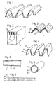
- the absorption element 1 shows the basic design of an absorption element 1. It consists of 2 coincidence conductors 2, which have a periodic, trapezoidal cross section. There is an intermediate space 3 between the two coincidence conductors 2. The intermediate space 3 is sealed gas-tight to the outside and is sealed with a gas with a high speed of sound, e.g. B. hydrogen or helium filled with ambient pressure.
- a gas with a high speed of sound e.g. B. hydrogen or helium filled with ambient pressure.
- the coincidence conductors 2 represent flexible waveguides. Given the wall thickness and trapezoidal height, they have an area moment of inertia in the axial direction. With the modulus of elasticity E, mass allocation m and at Excitation frequencies w the coincidence conductor has a bending wave velocity C ⁇ .
- a plurality of absorption elements 1 tuned to different frequencies are to be used to attenuate broadband noise signals.
- Materials with a high modulus of elasticity E and low density for example aluminum, fiber materials such as GRP and CFRP, beryllium and also steel, are particularly suitable as the material for the coincidence ladder 2.
- Fig. 2 shows an analogous embodiment to Fig. 1.
- the absorption element 11 consists of 2 coincidence conductors 12 with a wavy profile.
- In the intermediate space 13 there is again a gas with high speed of sound (hydrogen, helium) with ambient pressure and the roller-shaped fixings 14.
- the coincidence conductors 12 again represent flexible waveguides, the bending wave speed of which depends on that of the surrounding medium.
- B. air is matched.
- the absorption elements are attached, for example, in a ventilation duct 15.
- any cross-sectional shapes per se can be selected.
- the profile shape serves in particular to increase the area moment of inertia and thus the bending shaft speed.
- a double-corrugated profile shape of the coincidence waveguide 22 is shown.
- a pulling mechanism 23 is provided at the same time, by means of which the coincidence waveguides 22 can be stretched (shortened) in the transverse direction. This also changes the profile height and thus the bending shaft speed. In this way, these changed operating conditions can be adapted.
- An automatic, temperature-dependent control results when using bimetal strips. With barometer springs, pressure-dependent control can also be implemented.
- absorption elements 31 are shown in FIG. 4 for a broadband sound influencing, the coincidence conductors 32 of which have different profile heights and thus the coincidence speed adapted for the different frequencies of the sound speed.
- FIG. 5 shows an absorption element 41 in a longitudinal section. It is characterized in that the profile height of the coincidence conductors 42 increases in the longitudinal direction. Such a measure ensures, as in FIG. 4, that in the case of broadband noise, the individual noise frequencies each find suitable sections with a coincidence condition.
- FIG. 6 is a cross section through an absorption element 51 with a double tubular coincidence waveguide 52. In the gas-tight space 53 there is again gas with a high speed of sound.
- FIG. 7 shows the cross section of an absorption element 61 with coincidence waveguides 62 consisting of honeycomb plates, which are joined in a gas-tight manner to form the intermediate space 63.
- the cover plates oriented towards the intermediate space 63 expediently have openings 64, so that a relatively large volume is formed in the intermediate space 63.
- air can also be provided in the intermediate space 63 instead of a gas with a high speed of sound.
- FIG. 8 shows an absorption element 71 whose coincidence waveguide 72 executes membrane waves. It is spanned by a back shell 74.
- the space 73 between the coincidence waveguide 72 and the back shell 74 is evacuated or partially evacuated. In the latter case, the residual gas (hydrogen, helium) has a high speed of sound.
- the vacuum load results in a tensile load in the coincidence waveguide 72.
- the tensile load and mass assignment result in a frequency-independent membrane speed in a manner known per se. This is designed for coincidence with the surrounding medium.
- the pressure difference AP. from the front and back is the radius of curvature r, which gives the coincidence speed c.
- FIG. 9 shows an absorption element 81 integrated into a tube. It consists of a cylindrical coincidence waveguide 82 which is held by a tube jacket 84. The space 83 between the coincidence waveguide 82 and the tubular jacket 84 is fully or partially evacuated. As a result, there is a voltage in the coincidence waveguide 82, which results in a frequency-independent membrane wave velocity. Thanks to the transverse contraction, the primary ring stresses are also converted into longitudinal stresses, so that the membrane shaft speed can be made equal in both directions to the speed of sound of the medium flowing through the pipe.
- FIG. 10 shows the case inverse to FIG. 9.
- the absorption element 91 consists of a tubular coincidence waveguide 92. This is at an internal pressure AP., the compressed gas consisting of low molecular weight substances with a high speed of sound.
- the membrane pressure can be set to coincidence by the internal pressure.
- FIG. 11 shows a double-acting absorption element 101, which has tensioned membranes on its outer sides as coincidence waveguides 102.
- the tension a exists in both diaphragm directions, so that sound can be absorbed from all angular directions.
- a single-axis membrane tension is sufficient in narrow channels with a preferred direction.
- the tension itself can be maintained by springs 105 (e.g. buckling springs). These springs 105 are particularly recommended because of their spring constancy, so that the same membrane tension is always maintained regardless of expansions.
- the springs 105 themselves are supported on a middle plate 104.
- the interior 103 is filled with a gas of high speed of sound.
Landscapes
- Physics & Mathematics (AREA)
- Engineering & Computer Science (AREA)
- Acoustics & Sound (AREA)
- Multimedia (AREA)
- Soundproofing, Sound Blocking, And Sound Damping (AREA)
- Exhaust Silencers (AREA)
Abstract
Description
Die Erfindung bezieht sich auf ein Wandelement zur Schallabsorption mit geschlossener Oberfläche und hoher mechanischer, korrosiver und thermischer Festigkeit unter Ausnützung des Koinzidenzeffektes. Es ist beabsichtigt, eine Schalldämpfung und Schalldämmung in Kanälen, Kapseln, Räumen und bei Ansaug- und Auslassströmungen herbeizuführen.The invention relates to a wall element for sound absorption with a closed surface and high mechanical, corrosive and thermal strength using the coincidence effect. It is intended to provide sound insulation and sound insulation in ducts, capsules, rooms and in intake and outlet flows.
Bekannt für diese Aufgabenstellung sind Absorptionsmaterialien der verschiedensten Ausführungsformen. Bei diesen wird durch die Reibbewegung von Schallschnelle und Absorptionsstoff der Schall in Wärme überführt. Um hohe Absorptionswerte zu erreichen, kommt es darauf an, eine möglichst weiche, offenporige Absorberfläche und eine ausreichende Absorbertiefe zur Verfügung zu haben. Ausserdem ist beim Einsatz von absorbierenden Raumwänden bzw. Decken ein Mindestabstand von ca. einem Viertel der Schallwellenlänge vom Absorber zur Wand notwendig, um im Bereich wirksamer Schnellebewegungen zu liegen.Absorbent materials of various designs are known for this task. With these, the frictional movement of the sound fast and the absorption material converts the sound into heat. In order to achieve high absorption values, it is important to have a soft, open-pore absorber surface and a sufficient absorber depth. In addition, when using absorbent room walls or ceilings, a minimum distance of about a quarter of the sound wavelength from the absorber to the wall is necessary in order to be in the range of effective rapid movements.
Ein Nachteil der beschriebenen Absorptionsmaterialien ist deren geringe Widerstandsfähigkeit gegen mechanische Beanspruchung, Feuchtigkeit und Verrottung.A disadvantage of the absorption materials described is their low resistance to mechanical stress, moisture and rotting.
Mit DE-A1-P 25 31 866 ist ein Wandelement bekannt geworden, das ebenfalls den Koinzidenzeffekt zur Schallabsorption ausnützt. Der Nachteil dieser Konstruktion ist jedoch, dass diese Elemente Biegeschwinger sind und keinen Volumenhub aufweisen. Das hat zur Folge, dass diese nicht wirken, wenn sie beidseitig kohärent vom Schall beaufschlagt sind.With DE-A1-P 25 31 866 a wall element has become known which also uses the coincidence effect for sound absorption. The disadvantage of this construction, however, is that these elements are flexural vibrators and have no volume stroke. As a result, they do not work if they are coherently impacted by sound on both sides.
Aufgabe der Erfindung ist die Angabe eines Wandelementes zur Schallabsorption unter Ausnützung des Koinzidenzeffektes. Im besonderen sind Koinzidenzschwinger vorgesehen, die einen Volumenhub aufweisen. Damit ergibt sich gegenüber dem Stand der Technik auch eine Schall- dämpfung und Schalldämmung bei beidseitiger kohärenter Beaufschlagung mit Schall. Dank des Volumenhubes kommt es auch bei identischer Beaufschlagung der Vorder- und Rückseite zu keiner Aufhebung der auf beiden Seiten wirkenden Druckkräfte, sondern beide Seiten werden individuell zu Koinzidenzschwingungen angeregt. Das ergibt nicht nur eine doppelte Flächenausnützung, sondern erspart auch eine spezielle Abdeckung einer Wandseite zur Vermeidung einer Druckneutralisation.The object of the invention is to provide a wall element for sound absorption using the coincidence effect. In particular, coincidence transducers are provided which have a volume stroke. Compared to the prior art, this also results in sound attenuation and sound insulation with coherent exposure to sound on both sides. Thanks to the volume stroke, even when the front and rear sides are acted on identically, the pressure forces acting on both sides are not canceled, but both sides are individually excited to produce coincidence vibrations. This not only results in a double use of space, but also saves a special covering of one side of the wall to avoid pressure neutralization.
Erfindungsgemäss wird diese Aufgabe dadurch gelöst, dass Biegewellenleiter als Koinzidenzwellenleiter mit Profilformen mit hohem Flächenträgheitsmoment J, z.B. trapezförmig, wellenförmig und aus einem Material mit hohem Elastizitätsmodul E und geringer Dichte g, z.B. Aluminium, Beryllium, Stahl, GFK- und CFK-Materialien verwendet werden. Mit diesen Bedingungen lassen sich bei kleinem Flächengewicht und deshalb hoher akustischen Wirkung ausreichend hohe Biegewellengeschwindigkeiten erreichen.According to the invention, this object is achieved in that bending waveguides as coincidence waveguides with profile shapes with a high area moment of inertia J, e.g. trapezoidal, wavy and made of a material with high elastic modulus E and low density g, e.g. Aluminum, beryllium, steel, GRP and CFRP materials are used. With these conditions, sufficiently high bending wave speeds can be achieved with a low basis weight and therefore a high acoustic effect.
Nach einem weiteren Merkmal der Erfindung werden jeweils 2 Koinzidenzwellenleiter im wesentlichen parallel zusammengeschlossen, wobei der sich bildende Zwischenraum gasdicht abgeschlossen und mit einem Gas mit hoher Schallgeschwindigkeit, z. B. Helium, Wasserstoff gefüllt ist. Eine solche Massnahme ergibt im Zwischenraum dank der hohen Schallgeschwindigkeit Druckausgleich, so dass auch bei kleinem Abstand der Koinzidenzwellenleiter die Federeigenschaften des Gaspolsters weniger stören.According to a further feature of the invention, two coincidence waveguides are connected together essentially in parallel, the gap which is formed being sealed gas-tight and with a gas with high speed of sound, for. B. helium, hydrogen is filled. Such a measure results in pressure equalization in the space thanks to the high speed of sound, so that even with a small distance between the coincidence waveguides, the spring properties of the gas cushion are less disturbed.
Nach einem weiteren Merkmal der Erfindung werden als Kainzidenzwellenleiter flächen- oder streifenförmige Membrane verwendet, die unter einer zwei- oder einachsigen Zugbelastung stehen, so dass die Membranwellengeschwindigkeit gleich der Schallgeschwindigkeit des umgebenden Mediums ist. Die Zugbelastung bei planen Membranflächen kann durch die Randeinspannung erfolgen. Eine andere Möglichkeit besteht darin, durch einseitige Vakuum- oder Unterdruckbelastung gewölbte Membranflächen unter Zugbelastung zu halten.According to a further feature of the invention, flat or strip-shaped membranes are used as the coincidence waveguides, which are under a biaxial or uniaxial tensile load, so that the membrane wave velocity is equal to the speed of sound of the surrounding medium. The tensile load on flat membrane surfaces can be caused by the edge clamping. Another possibility is to hold curved membrane surfaces under tensile load by one-sided vacuum or vacuum pressure.
Nach einem weiteren Merkmal der Erfindung sind die Ränder der als Koinzidenzwellenleiterverwendeten Biegewellenleiter nicht fest gegeneinander fixiert, sondern können dank einer federweichen Verbindnung frei schwingen. Dadurch wirkt die gesamte Länge des Koinzidenzwellenleiters. Im weiteren ist das in Schallrichtung gesehen hintere Ende des Koinzidenzwellenleiters bedämpft. Dies kann in an sich bekannter Weise durch einen reflexionsfreien Abschluss des Koinzidenzwellenleiters erreicht werden. In diesem Fall ist die Abschlussimpedanz auf die des Biegewellenleiters abgestimmt. Dieser Mechanismus wird beispielsweise auch bei der Randdämpfung von Fensterscheiben mittels Kitt angewendet.According to a further feature of the invention, the edges of the flexible waveguides used as coincidence waveguides are not fixed against each other, but can swing freely thanks to a spring-soft connection. As a result, the entire length of the coincidence waveguide acts. Furthermore, the rear end of the coincidence waveguide, as seen in the sound direction, is damped. This can be achieved in a manner known per se by a reflection-free termination of the coincidence waveguide. In this case, the terminating impedance is matched to that of the flexible waveguide. This mechanism is also used, for example, for the edge damping of window panes using putty.
Nach einem weiteren Merkmal der Erfindung werden die Koinzidenzwellenleiter zusätzlich mit konventionellen, porösen Absorptionsmatten abgedeckt. Damit können insbesondere die hohen Frequenzen gedämpft werden.According to a further feature of the invention, the coincidence waveguides are additionally covered with conventional, porous absorption mats. The high frequencies in particular can thus be damped.
Die Erfindung ist anhand der folgende zeich- nungsbeschreibungen näher erläutert. Es zeigen.
- Fig. 1 bis Fig. 7 Absorbtionselemente mit Koinzidenzwellenleitern unter Benützung von Biegewellen,
- Fig. 8 bis Fig. 11 Absorptionselemente mit Koinzidenzwellenleitern unter Benützung von Membranwellen.
- 1 to 7 absorption elements with coincidence waveguides using bending waves,
- 8 to 11 absorption elements with coincidence waveguides using membrane waves.
Fig. 1 zeigt die Grundausführung eines Absorptionselementes 1. Es besteht aus 2 Koinzidenzleitern 2, die einen periodischen, trapezförmigen Querschnitt aufweisen. Zwischen den beiden Koinzidenzleitern 2 befindet sich ein Zwischenraum 3. Der Zwischenraum 3 ist gasdicht nach aussen abgeschlossen und ist mit einem Gas mit hoher Schallgeschwindigkeit, z. B. Wasserstoff oder Helium mit Umgebungsdruck gefüllt.1 shows the basic design of an
Zur gegenseitigen Fixierung dienen Distanzhalter 4 in Rollenform. Die Koinzidenzleiter 2 stellen Biegewellenleiter dar. Gegeben durch Wandstärke und Trapezhöhe weisen diese in Achsenrichtung ein Flächenträgheitsmoment auf. Mit dem Elastizitätsmodul E, Massenbelegung m und bei der Anregungsfrequenzen w hat der Koinzidenzleiter eine Biegewellengeschwindigkeit Cε.
Diese wird nun so gewählt, dass sie mit der Spurgeschwindigkeit Cs einer unter dem Winkel a einfallenden Schallwelle übereinstimmt.![]()
![]()
Zur Dämpfung breitbandiger Lärmsignale sind mehrere auf verschiedene Frequenzen abgestimmte Absorptionselemente 1 zu verwenden. Bei parallelem Schalleinfall ist insbesondere Cs = C = CB (C = Schallgeschwindigkeit). Als Material für die Koinzidenzleiter 2 eignen sich insbesondere Stoffe mit hohem Elastizitätsmodul E und kleiner Dichte, z.B. Aluminium, Faserstoffe wie GFK und CFK, Beryllium und auch Stahl.A plurality of
Fig. 2 stellt eine analoge Ausführung zu Fig. 1 dar. Das Absorptionselement 11 besteht aus 2 Koinzidenzleitern 12 mit wellenförmigem Profil. Im Zwischenraum 13 befindet sich wieder ein Gas mit hoher Schallgeschwindigkeit (Wasserstoff, Helium) mit Umgebungsdruck und die rollenförmigen Fixierungen 14.Fig. 2 shows an analogous embodiment to Fig. 1. The
Die Koinzidenzleiter 12 stellen wieder Biegewellenleiter dar, deren Biegewellengeschwindigkeit auf die des umgebenden Mediums z. B. Luft abgestimmt ist. Die Absorptionselemente sind beispielsweise in einem Lüftungskanal 15 angebracht.The
Neben den in den vorangegangenen Beschreibungsbeispielen Trapez- oder Wellenform des Koinzidenzleiterquerschnitt können an sich beliebige Querschnittsformen gewählt werden. Die Profilform dient im besonderen zur Erhöhung der Flächenträgheitsmomentes und damit der Biegewellengeschwindigkeit. In Fig. 3 beispielsweise ist eine doppelt gewellte Profilform der Koinzidenzwellenleiter 22 dargestellt. In diesem Fall ist gleichzeitig ein Zugmechanismus 23 vorgesehen, durch den die Koinzidenzwellenleiter 22 in Querrichtung gestreckt (verkürzt) werden können. Dadurch ändert sich auch die Profilhöhe und damit die Biegewellengeschwindigkeit. Auf diese Weise kann diese veränderten Betriebsbedingungen angepasst werden. Eine automatische, temperaturabhängige Regelung ergibt sich bei Verwendung von Bimetallstreifen. Durch Barometerfedern lässt sich analog eine druckabhängige Regelung realisieren.In addition to the trapezoidal or waveform of the coincidence conductor cross section in the preceding description examples, any cross-sectional shapes per se can be selected. The profile shape serves in particular to increase the area moment of inertia and thus the bending shaft speed. 3, for example, a double-corrugated profile shape of the
Da die Biegewellengeschwindigkeit frequenzabhängig ist, sind für eine breitbandige Schallbeeinflussung in Fig.4 Absorptionselemente 31 dargestellt, deren Koinzidenzleiter 32 unterschiedliche Profilhöhe und damit für die unterschiedlichen Frequenzen der Schallgeschwindigkeit angepasste Koinzidenzgeschwindigkeit aufweisen.Since the bending wave speed is frequency-dependent,
In Fig. 5 ist ein Absorptionselement 41 im Längsschnitt dargestellt. Es ist dadurch gekennzeichnet, dass die Profilhöhe der Koinzidenzleiter 42 in Längsrichtung anwächst. Eine solche Massnahme gewährleistet wie in Fig. 4, dass bei breitbandigem Lärm die einzelnen Lärmfrequenzen jeweils passende Abschnitte mit Koinzidenzbedingung finden.5 shows an
Fig. 6 ist ein Querschnitt durch ein Absorptionselement 51 mit einem doppelrohrförmigen Koinzidenzwellenleiter 52. Im gasdicht abgeschlossenen Zwischenraum 53 befindet sich wieder Gas mit hoher Schallgeschwindigkeit.6 is a cross section through an absorption element 51 with a double
Fig.'7 zeigt den Querschnitt eines Absorptionselementes 61 mit aus Honeycomb-Platten bestehenden Koinzidenzwellenleiter 62, die unter Bildung des Zwischenraumes 63 gasdicht zusammengefügt sind. Zweckmässigerweise haben die zum Zwischenraum 63 hin orientierten Deckplatten Öffnungen 64, so dass ein relativ grosses Volumen im Zwischenraum 63 gebildet wird. In diesem Fall kann anstelle eines Gases mit hoher Schallgeschwindigkeit auch Luft im Zwischenraum 63 vorgesehen werden.FIG. 7 shows the cross section of an
Während in den Ausführungsbeispielen nach Fig. 1 bis 7 jeweils Biegewellenleiter benützt wurden, sind in Fig. 8 bis 11 Membranwellenleiter zugrundegelegt.While bending waveguides were used in the exemplary embodiments according to FIGS. 1 to 7, membrane waveguides are used as the basis in FIGS. 8 to 11.
Fig. 8 stellt ein Absorptionselement 71 dar, dessen Koinzidenzwellenleiter 72 Membranwellen ausführt. Es wird aufgespannt durch eine Rückenschale 74. Der Raum 73 zwischen Koinzidenzwellenleiter 72 und Rückenschale 74 ist evakuiert oder teilevakuiert. Im letzteren Fall hat das Restgas (Wasserstoff, Helium) eine hohe Schallgeschwindigkeit. Die Unterdruckbelastung ergibt in dem Koinzidenzwellenleiter 72 eine Zugbelastung. Zugbelastung und Massenbelegung ergibt in an sich bekannter Weise eine frequenzunabhängige Membrangeschwindigkeit. Diese wird auf Koinzidenz mit dem Umgebungsmedium ausgelegt.8 shows an
Da die Druckbelastung des Koinzidenzwellenleiter 72 eine Krümmung ergibt, ist es vorteilhaft, eine solche Konstruktion gleichzeitig als Umlenkelement in einem Krümmer einzusetzen.Since the pressure load on the
Bei einer Massenbelegung m der Membran, dem Druckunterschied AP. von Vorder- und Rückseite beträgt der Krümmungsradius r, der die Koinzidenzgeschwindigkeit c ergibt.![]()
![]()
Fig. 9 stellt ein zu einem Rohr integrierten Absorptionselement 81 dar. Es besteht aus einem zylinderförmigen Koinzidenzwellenleiter 82, der durch einen Rohrmantel 84 gehalten ist. Der Raum 83 zwischen Koinzidenzwellenleiter 82 und Rohrmantel 84 ist voll- oder teilevakuiert. Dadurch besteht eine Spannung im Koinzidenzwellenleiter 82, die eine frequenzunabhängige Membranwellengeschwindigkeit ergibt. Dank der Querkontraktion setzen sich die primären Ringspannungen ebenfalls in Längsspannungen um, so dass die Membranwellengeschwindigkeit in beiden Richtungen gleich der Schallgeschwindigkeit des das Rohr druchströmenden Mediums gemacht werden kann.FIG. 9 shows an
Fig. 10 stellt den zu Fig. 9 inversen Fall dar. Hier besteht das Absorptionselement 91 aus einem schlauchförmigen Koinzidenzwellenleiter 92. Dieser steht unter einem Innendruck AP., wobei das Druckgas aus niedermolekularen Stoffen mit hoher Schallgeschwindigkeit besteht. Durch den Innendruck kann analog die Membranwellengeschwindigkeit auf Koinzidenz eingestellt werden.FIG. 10 shows the case inverse to FIG. 9. Here the
Fig. 11 zeigt ein zweiseitig wirkendes Absorptionselement 101, das an seinen Aussenseiten gespannte Membrane als Koinzidenzwellenleiter 102 aufweist. Bei einer Membrandichte p [kg/m3] erhält diese eine Spannung a [N/m], so dass die Membrangeschwindigkeit CM = V α/g gleich der Schallgeschwindigkeit des umgebenden Mediums, z.B. Luft ist. Die Spannung a besteht in beiden Membranrichtungen, so dass Schall aus allen Winkelrichtungen absorbiert werden kann. In engen Kanälen mit einer Vorzugsrichtung genügt eine einachsige Membranspannung.FIG. 11 shows a double-acting
Die Spannung selbst kann durch Federn 105 (z. B. Knickfedern) aufrechterhalten werden. Diese Federn 105 empfehlen sich besonders wegen ihrer Federkonstanz, so dass unabhängig von Dehnungen immer dieselbe Membranspannung aufrecht erhalten wird. Die Federn 105 selbst stützen sich auf eine Mittelplatte 104 ab. Der Innenraum 103 ist mit einem Gas grosser Schallgeschwindigkeit erfüllt.The tension itself can be maintained by springs 105 (e.g. buckling springs). These
Claims (9)
Priority Applications (1)
| Application Number | Priority Date | Filing Date | Title |
|---|---|---|---|
| AT81104147T ATE9119T1 (en) | 1980-06-02 | 1981-05-30 | COINCIDENCE SILENCER. |
Applications Claiming Priority (2)
| Application Number | Priority Date | Filing Date | Title |
|---|---|---|---|
| DE19803020830 DE3020830A1 (en) | 1980-06-02 | 1980-06-02 | COINCIDENCE SILENCER |
| DE3020830 | 1980-06-02 |
Publications (2)
| Publication Number | Publication Date |
|---|---|
| EP0041260A1 EP0041260A1 (en) | 1981-12-09 |
| EP0041260B1 true EP0041260B1 (en) | 1984-08-22 |
Family
ID=6103735
Family Applications (1)
| Application Number | Title | Priority Date | Filing Date |
|---|---|---|---|
| EP81104147A Expired EP0041260B1 (en) | 1980-06-02 | 1981-05-30 | Sound absorbing element utilizing the effect of coincidence |
Country Status (3)
| Country | Link |
|---|---|
| EP (1) | EP0041260B1 (en) |
| AT (1) | ATE9119T1 (en) |
| DE (1) | DE3020830A1 (en) |
Families Citing this family (3)
| Publication number | Priority date | Publication date | Assignee | Title |
|---|---|---|---|---|
| DE4217767C1 (en) * | 1992-05-29 | 1993-08-26 | Deutsche Aerospace Ag, 8000 Muenchen, De | |
| FR2704969B1 (en) * | 1993-05-06 | 1995-07-28 | Centre Scient Tech Batiment | Acoustic attenuation device with active double wall. |
| FR2726681B1 (en) * | 1994-11-03 | 1997-01-17 | Centre Scient Tech Batiment | ACTIVE DOUBLE WALL ACOUSTIC MITIGATION DEVICE |
Family Cites Families (12)
| Publication number | Priority date | Publication date | Assignee | Title |
|---|---|---|---|---|
| DE1572497A1 (en) * | 1967-06-27 | 1970-02-19 | Siemens Ag | Sound insulation bodies, in particular for encapsulating machines |
| DE1803810A1 (en) * | 1967-10-21 | 1969-06-12 | Waertsilae Oy Ab | Sound absorbers, especially for water pipes |
| DE2215083B2 (en) * | 1972-03-28 | 1975-01-09 | Max-Planck-Gesellschaft Zur Foerderung Der Wissenschaften E.V., 3400 Goettingen | Device for reducing the propagation of sound in liquid-filled pipes and ducts |
| DE2540439A1 (en) * | 1974-09-16 | 1976-03-25 | Bfg Glassgroup | Multiple glazing unit - with different thickness panes enclosed controlled atmospheres |
| DE2527440A1 (en) * | 1975-06-20 | 1976-12-30 | Schmidt Ernst Guenther Dipl Ph | Sound damping by isolating sources - uses evacuated cells whose walls need stand only a few cm. outside ach each sound source |
| DE2531866C2 (en) * | 1975-07-17 | 1981-11-12 | Messerschmitt-Bölkow-Blohm GmbH, 8000 München | Wall element for broadband sound absorption using the coincidence effect |
| DE2609872A1 (en) * | 1976-03-10 | 1977-09-15 | Freudenberg Carl Fa | Absorption sound damper for flow channels - with flat structures of closed cell soft foam contg. lead balls |
| DE2834823C2 (en) * | 1978-08-09 | 1980-07-17 | Messerschmitt-Boelkow-Blohm Gmbh, 8000 Muenchen | Volume-changing resonators based on the disc spring principle |
| DE2746061A1 (en) * | 1977-10-13 | 1979-04-19 | Rolf Jerke | Heat and sound insulating panel - comprises hollow casing with evacuated interior supported against collapse by small dia. spacers |
| DK142710B (en) * | 1977-11-10 | 1980-12-29 | Elektronikcentralen | Sound absorbing structure. |
| DE2965890D1 (en) * | 1979-03-07 | 1983-08-25 | Caterpillar Tractor Co | Hydraulic noise attenuator |
| DE2947026C2 (en) * | 1979-11-22 | 1981-10-01 | Messerschmitt-Bölkow-Blohm GmbH, 8000 München | Silators to reduce noise |
-
1980
- 1980-06-02 DE DE19803020830 patent/DE3020830A1/en not_active Withdrawn
-
1981
- 1981-05-30 EP EP81104147A patent/EP0041260B1/en not_active Expired
- 1981-05-30 AT AT81104147T patent/ATE9119T1/en not_active IP Right Cessation
Also Published As
| Publication number | Publication date |
|---|---|
| ATE9119T1 (en) | 1984-09-15 |
| DE3020830A1 (en) | 1981-12-10 |
| EP0041260A1 (en) | 1981-12-09 |
Similar Documents
| Publication | Publication Date | Title |
|---|---|---|
| DE69525886T2 (en) | Sound absorption arrangement using a porous material | |
| DE3715999C2 (en) | ||
| DE19509972C2 (en) | Sandwich plate | |
| US7395898B2 (en) | Sound attenuating structures | |
| DE2834823C2 (en) | Volume-changing resonators based on the disc spring principle | |
| EP0477418A1 (en) | Ultrasonic flowmeter unit to be intented in a measuring tube | |
| DE4408782A1 (en) | Foil sound absorber | |
| DE112006002411T5 (en) | Double-wall structure | |
| EP0041260B1 (en) | Sound absorbing element utilizing the effect of coincidence | |
| EP0368105A2 (en) | Deformable wall | |
| EP0894253A1 (en) | Wind tunnel | |
| Roy et al. | Wave attenuation in periodic structures | |
| DE102015103936A1 (en) | Sound insulation device with a membrane and a mass | |
| EP0742322B1 (en) | Sound damping device | |
| DE112005002128T5 (en) | Double-wall structure | |
| DE4409200A1 (en) | Sound shield plate and application of a sound shield plate to the floor assembly of an engine compartment of a motor vehicle | |
| DE602004005060T2 (en) | ELECTROMECHANICAL POWER TRANSFORMER | |
| EP3246479B1 (en) | Absorber unit for absorbing sound | |
| DE8032078U1 (en) | Coincidence silencer | |
| CH646407A5 (en) | INSULATED GLASS UNIT. | |
| DE7838529U1 (en) | SOUND AND THERMAL INSULATION MULTI-PANEL INSULATED GLAZING | |
| DE2609872A1 (en) | Absorption sound damper for flow channels - with flat structures of closed cell soft foam contg. lead balls | |
| EP2104934A2 (en) | Underwater antenna | |
| DE3217783C2 (en) | Sound-absorbing and sound-absorbing element with resonators | |
| DE19524705C2 (en) | Device and method for local and directional detection of sound waves |
Legal Events
| Date | Code | Title | Description |
|---|---|---|---|
| PUAI | Public reference made under article 153(3) epc to a published international application that has entered the european phase |
Free format text: ORIGINAL CODE: 0009012 |
|
| AK | Designated contracting states |
Designated state(s): AT FR GB IT |
|
| RBV | Designated contracting states (corrected) |
Designated state(s): AT FR GB IT |
|
| 17P | Request for examination filed |
Effective date: 19820607 |
|
| ITF | It: translation for a ep patent filed | ||
| GRAA | (expected) grant |
Free format text: ORIGINAL CODE: 0009210 |
|
| AK | Designated contracting states |
Designated state(s): AT FR GB IT |
|
| REF | Corresponds to: |
Ref document number: 9119 Country of ref document: AT Date of ref document: 19840915 Kind code of ref document: T |
|
| ET | Fr: translation filed | ||
| PG25 | Lapsed in a contracting state [announced via postgrant information from national office to epo] |
Ref country code: AT Effective date: 19850530 |
|
| PLBE | No opposition filed within time limit |
Free format text: ORIGINAL CODE: 0009261 |
|
| STAA | Information on the status of an ep patent application or granted ep patent |
Free format text: STATUS: NO OPPOSITION FILED WITHIN TIME LIMIT |
|
| 26N | No opposition filed | ||
| PG25 | Lapsed in a contracting state [announced via postgrant information from national office to epo] |
Ref country code: FR Free format text: LAPSE BECAUSE OF NON-PAYMENT OF DUE FEES Effective date: 19880129 |
|
| REG | Reference to a national code |
Ref country code: FR Ref legal event code: ST |
|
| PG25 | Lapsed in a contracting state [announced via postgrant information from national office to epo] |
Ref country code: GB Free format text: LAPSE BECAUSE OF NON-PAYMENT OF DUE FEES Effective date: 19881118 |