EP0008049B1 - Dc micromotor for driving a dental tool - Google Patents
Dc micromotor for driving a dental tool Download PDFInfo
- Publication number
- EP0008049B1 EP0008049B1 EP79102687A EP79102687A EP0008049B1 EP 0008049 B1 EP0008049 B1 EP 0008049B1 EP 79102687 A EP79102687 A EP 79102687A EP 79102687 A EP79102687 A EP 79102687A EP 0008049 B1 EP0008049 B1 EP 0008049B1
- Authority
- EP
- European Patent Office
- Prior art keywords
- sleeve
- motor
- permanent magnets
- sections
- miniature
- Prior art date
- Legal status (The legal status is an assumption and is not a legal conclusion. Google has not performed a legal analysis and makes no representation as to the accuracy of the status listed.)
- Expired
Links
- 239000000696 magnetic material Substances 0.000 claims abstract description 13
- 230000004907 flux Effects 0.000 claims description 22
- 239000000463 material Substances 0.000 claims description 6
- XEEYBQQBJWHFJM-UHFFFAOYSA-N Iron Chemical compound [Fe] XEEYBQQBJWHFJM-UHFFFAOYSA-N 0.000 description 20
- 230000008859 change Effects 0.000 description 13
- 229910052742 iron Inorganic materials 0.000 description 10
- 230000005284 excitation Effects 0.000 description 3
- 230000006698 induction Effects 0.000 description 3
- 230000008901 benefit Effects 0.000 description 2
- 230000005540 biological transmission Effects 0.000 description 2
- 238000005553 drilling Methods 0.000 description 2
- 238000000227 grinding Methods 0.000 description 2
- 230000006872 improvement Effects 0.000 description 2
- 238000003801 milling Methods 0.000 description 2
- 230000035699 permeability Effects 0.000 description 2
- 230000009467 reduction Effects 0.000 description 2
- 229910052772 Samarium Inorganic materials 0.000 description 1
- 230000008878 coupling Effects 0.000 description 1
- 238000010168 coupling process Methods 0.000 description 1
- 238000005859 coupling reaction Methods 0.000 description 1
- 230000005347 demagnetization Effects 0.000 description 1
- 230000001419 dependent effect Effects 0.000 description 1
- 238000010586 diagram Methods 0.000 description 1
- 238000005516 engineering process Methods 0.000 description 1
- 238000012423 maintenance Methods 0.000 description 1
- 238000004519 manufacturing process Methods 0.000 description 1
- 239000012811 non-conductive material Substances 0.000 description 1
- 238000005498 polishing Methods 0.000 description 1
- 230000000069 prophylactic effect Effects 0.000 description 1
- 230000001681 protective effect Effects 0.000 description 1
- KZUNJOHGWZRPMI-UHFFFAOYSA-N samarium atom Chemical compound [Sm] KZUNJOHGWZRPMI-UHFFFAOYSA-N 0.000 description 1
- 229920006395 saturated elastomer Polymers 0.000 description 1
- 230000007704 transition Effects 0.000 description 1
- 230000003313 weakening effect Effects 0.000 description 1
Images

Classifications
-
- A—HUMAN NECESSITIES
- A61—MEDICAL OR VETERINARY SCIENCE; HYGIENE
- A61C—DENTISTRY; APPARATUS OR METHODS FOR ORAL OR DENTAL HYGIENE
- A61C1/00—Dental machines for boring or cutting ; General features of dental machines or apparatus, e.g. hand-piece design
- A61C1/02—Dental machines for boring or cutting ; General features of dental machines or apparatus, e.g. hand-piece design characterised by the drive of the dental tools
- A61C1/06—Dental machines for boring or cutting ; General features of dental machines or apparatus, e.g. hand-piece design characterised by the drive of the dental tools with electric drive
-
- H—ELECTRICITY
- H02—GENERATION; CONVERSION OR DISTRIBUTION OF ELECTRIC POWER
- H02K—DYNAMO-ELECTRIC MACHINES
- H02K23/00—DC commutator motors or generators having mechanical commutator; Universal AC/DC commutator motors
- H02K23/02—DC commutator motors or generators having mechanical commutator; Universal AC/DC commutator motors characterised by arrangement for exciting
- H02K23/04—DC commutator motors or generators having mechanical commutator; Universal AC/DC commutator motors characterised by arrangement for exciting having permanent magnet excitation
-
- H—ELECTRICITY
- H02—GENERATION; CONVERSION OR DISTRIBUTION OF ELECTRIC POWER
- H02K—DYNAMO-ELECTRIC MACHINES
- H02K23/00—DC commutator motors or generators having mechanical commutator; Universal AC/DC commutator motors
- H02K23/40—DC commutator motors or generators having mechanical commutator; Universal AC/DC commutator motors characterised by the arrangement of the magnet circuits
- H02K23/44—DC commutator motors or generators having mechanical commutator; Universal AC/DC commutator motors characterised by the arrangement of the magnet circuits having movable, e.g. turnable, iron parts
Definitions
- the invention relates to a DC miniature motor with permanent magnetic excitation for driving a tool rotatably mounted in a dental hand instrument, containing a cylindrical motor housing with a stationary backing and for this purpose soft magnetic material, in the diametrically opposed pairs of permanent magnets Excitation of the armature are arranged.
- a small machine in which a revolving armature is provided between a fixed permanent magnet core and a return ring for setting the engine speed, also within the framework of optimal setting of the working point.
- the return ring is screwable in the motor housing and can be moved axially against the permanent magnet core.
- the invention specified in claims 1 and 4 is based on the object to provide an improvement and simplification.
- a small DC motor for driving dental tools is to be created in which the speed range can be changed while largely maintaining the power and the previous speed setting option (by changing the armature voltage) without having to exchange or change the gearbox with the different mechanical gearboxes provided handpiece parts is required.
- a major advantage of the invention is the fact that the previously required basic set of straight and contra-angle handpieces with different gear ratios can be considerably reduced, which results in less frequent coupling and uncoupling of the instruments to and from the drive part.
- the drive motor 1 shows a diagram of a drive motor 1 for a dental handpiece and contra-angle handpiece 2.
- the drive motor 1 an electric DC motor with permanent magnetic excitation, is connected via a supply hose (not shown) which is attached to the rear end 3 of the motor. supplied with electrical energy, contact members 4 being provided for the current transmission from the supply hose to the motor.
- a protective sleeve 6 surrounding the drive shaft 5 of the motor projects from the front end of the motor housing.
- the drive shaft 5 is in engagement with a drive shaft 7 of the handpiece 2, which drives a tool 9 (e.g. drill) which is rotatably mounted on the head part 8.
- a tool 9 e.g. drill
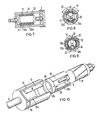
- FIG. 2 shows a basic illustration of the motor 1 with the sleeve 10 partially pushed on.
- 11 denotes the rotor or armature of the motor, 12, 12a two diametrically opposed permanent magnets with a length L and 13 the permanent magnets receiving motor housing, which parts together form the stator of the motor.
- the housing 13 is also made of soft magnetic material and simultaneously represents the magnetic yoke of the stator magnets for the magnetic flux both in the area of the permanent magnets and on the end face.
- the yoke thus formed is a stationary yoke, in contrast to the push-on sleeve 10 made of a material soft magnetic properties, which represents a variable conclusion.
- the wall thickness of the sleeve 10 which can be pushed over the housing 13 is considerably thicker in comparison to the housing wall thickness; with an assumed housing wall thickness of approximately 0.6 mm, it is somewhat three to four times this wall thickness.
- Suitable materials for the permanent magnets 12, 12a are all those materials which have a demagnetization characteristic that is as flat as possible, but advantageously Cobald Samarium (CoSm S ).
- the drive motor is shown once without (FIG. 3) and once with (FIG. 4) the sleeve 10 pushed on.
- the pushed-on sleeve 10 allows the magnetic flux to be changed both with regard to the flow through the armature and with regard to the return flow.
- the magnetic resistance between the pole ends of the magnets is significantly lower than without the sleeve.
- the reduction factor for a speed range reduction is approximately 0.5, depending on the thickness of the sleeve.
- the flux determining the speed is limited by reaching the magnetic saturation at a certain wall thickness of the sleeve forming the inference.
- the speed range which can be changed by changing the flow makes it possible to dispense with gear ratios in the handpiece 2, as a result of which the handpiece 2 can be manufactured considerably more easily.
- the handpieces only need to be equipped with or without a sleeve, depending on the speed range for which they are required.
- the sleeve 10 can also be detachably held as a separate part on the handpiece 2 or can also be part of the drive motor 1.
- FIGS. 5 and 6 show a variant of the embodiment shown in FIGS. 2 to 4.
- a sleeve 14 with diametrically opposite recesses 15 is provided, the two rod-shaped sections 16, 16a with an annular cross section and a circumference form an angle of approximately 120 °.
- the sections 16, 16a are connected to one another at the end face by webs or the like made of preferably magnetically non-conductive material.
- the sleeve 14 with the two sections 16, 16a is arranged such that it can be rotated through 90 ° relative to the motor housing 13, so that the two sections 16, 16a can be brought into the position shown in FIG. 6, in which they hold the ends of the permanent magnets 12, 12a overlap each other so that there is a good flow transition from the permanent magnets 12, 12a to the sections 16, 16a.
- this position there is a larger yoke cross section with a lower magnetic resistance and thus a better magnetic yoke compared to the position according to FIG. 5.
- According to the relationship 6 again results in a reduced speed of the motor.
- a change in speed is achieved by changing the air gap between the stator and rotor and by a magnetic short circuit (shunt) of the magnets.
- the motor housing again consisting of soft magnetic material, in the exemplary embodiment according to FIG. 7 is relatively thick-walled, so that a relatively high stationary inference, but no leakage flux, is already present to the outside.
- the magnetic resistance between the pole ends of the magnets is also low.
- Between the permanent magnets 12, 12a and the rotor 11 are two yoke elements 22, 22a made of soft magnetic material which, as can be seen from FIGS. 8 and 9, can be inserted between the stator 13 and rotor 11, so that the effective Air gap between the permanent magnets 12, 12a and the rotor 11 is changed.
- the yoke elements 22, 22a extend essentially over the same angular range a as the permanent magnets 12, 12a.
- FIG. 10 shows the exemplary embodiment shown schematically in FIGS. 7 to 9 again in a diagrammatic representation, in particular in order to show the possibility of adjustment for the inference elements 22, 22a.
- the two inference elements are held by a ring 24, which is made of a non-magnetic material to prevent magnetic short circuits.
- An actuating pin 25 protrudes radially from the ring 24 and protrudes radially from a guide groove 26 arranged in the motor housing 13 over an angular range of 90 °.
- H m is the field strength in the magnet
- ⁇ R v the sum of all air gap resistances in the magnetic circuit.
- the speed can be changed over a larger range (by a factor of 0.5 to a maximum of 0.3).
- the speed can also be changed in a known manner for a fine adjustment by changing the armature voltage.
Landscapes
- Health & Medical Sciences (AREA)
- Engineering & Computer Science (AREA)
- Power Engineering (AREA)
- Life Sciences & Earth Sciences (AREA)
- Dentistry (AREA)
- Epidemiology (AREA)
- Oral & Maxillofacial Surgery (AREA)
- Animal Behavior & Ethology (AREA)
- General Health & Medical Sciences (AREA)
- Public Health (AREA)
- Veterinary Medicine (AREA)
- Dental Tools And Instruments Or Auxiliary Dental Instruments (AREA)
- Dc Machiner (AREA)
- Permanent Field Magnets Of Synchronous Machinery (AREA)
Abstract
Description
Die Erfindung bezieht sich auf einen Gleichstrom-Kleinstmotor mit permanentmagnetischer Erregung zum Antrieb eines in einem zahnärztlichen Handinstrument drehbar gelagerten Werkzeuges, enthaltend ein zylindrisches Motorgehäuse mit einer einen stationären Rückschluß bildenden und zu diesem Zweck weichmagnetischen Material Bestehenden Hülse, in der diametral einander gegenüberliegend paarweise Dauermagnete zur Erregung des Ankers angeordnet sind.The invention relates to a DC miniature motor with permanent magnetic excitation for driving a tool rotatably mounted in a dental hand instrument, containing a cylindrical motor housing with a stationary backing and for this purpose soft magnetic material, in the diametrically opposed pairs of permanent magnets Excitation of the armature are arranged.
Bei solchen Kleinstmotoren ist es an sich üblich, die Drehzahl innerhalb eines vorgegebenen Drehzahlbereiches kontinuierlich zu ändern. Dies geschieht in bekannter Weise z.B. mit Hilfe eines als Fußschalter ausgebildeten Potentiometers durch Änderung der Ankerspannung. Der mit dem Potentiometer zu bestreichende Drehzahlbereich beträgt etwa 1:10, z.B. 4.000 bis 40.000 Upm, oder 12.000 bis 120.000 Upm, je nachdem, welches Handstück verwendet wird.In the case of such small motors, it is per se common to change the speed continuously within a predetermined speed range. This is done in a known manner e.g. with the help of a potentiometer designed as a foot switch by changing the armature voltage. The speed range to be covered with the potentiometer is about 1:10, e.g. 4,000 to 40,000 rpm, or 12,000 to 120,000 rpm, depending on which handpiece is used.
Bei nicht für zahnärztliche Zwecke (zum Antrieb von zahnärztlichen Werkzeugen) bestimmten Gleichstrommotoren ist es bekannt, zum Zwecke des optimalen Einstellens bzw. Bestimmens des Arbeitspunktes de Motors dessen Magnetfluß zu ändern. In der CH-A-391 070 beispielsweise wird hierzu u.a. vorgeschlagen, auf die Innenflächen der beiden Dauermagnete, auf denen außen ein als Rückschluß dienender Zylinder aus Weicheisen sitzt, einen abgeschrägten Weicheisenzylinder verfrehbar anzuordnen. Nach dem Zusammenbau des Motors kann mit Hilfe eines Werkzeuges, das von außen in eine Aussparung eingeführt wird, der abgeschrägte Weicheisenzylinder verdreht und damit der Magnetfluß des Motors verändert werden.In the case of direct current motors which are not intended for dental purposes (for driving dental tools), it is known to change the magnetic flux of the motor for the purpose of optimally setting or determining the operating point of the motor. In CH-A-391 070, for example, proposed to arrange a beveled soft iron cylinder on the inner surfaces of the two permanent magnets, on which there is a soft iron cylinder serving as a yoke. After assembling the motor, the beveled soft iron cylinder can be rotated with the help of a tool that is inserted from the outside into a recess, and thus the magnetic flux of the motor can be changed.
Um insbesondere die Anlaufspannung eines Elektromotors ändern zu können, ist es außerdem aus der FR-A-467 012 bekannt, in den Luftspalt zwischen Läufer und Magnetpolen des Ständers einen Ring mit Segmenten aus weichmagnetischem Material anzuordnen und den Ring verdrehbar zu lagern. Durch Verdrehen des Ringes kann so der Magnetfluß und damit die Anlaufspannung des Motors verändert werden. Nähere Details, insbesondere über die Verstellbarkeit des Ringes, sind der Druckschrift nicht zu entnehmen.In order to be able in particular to change the starting voltage of an electric motor, it is also known from FR-A-467 012 to arrange a ring with segments of soft magnetic material in the air gap between the rotor and the magnetic poles of the stator and to rotate the ring. By turning the ring, the magnetic flux and thus the starting voltage of the motor can be changed. Further details, in particular about the adjustability of the ring, cannot be found in the publication.
Aus der DE-C-939 463 ist außerdem eine Kleinmaschine bekannt, beit der zur Einstellung' der Motordrehzahl ebenfalls im Rahmen eines optimalen Einstellens des Arbeitspunktes ein umlaufender Anker zwischen einem feststehenden Dauermagnetkern und einem Rückschlußring vergesehen ist. Der Rückschlußring ist schraubbar im Motorgehäuse angeordnet und läßt sich axial gegen den Dauermagnetkern verschieben.From DE-C-939 463 a small machine is also known, in which a revolving armature is provided between a fixed permanent magnet core and a return ring for setting the engine speed, also within the framework of optimal setting of the working point. The return ring is screwable in the motor housing and can be moved axially against the permanent magnet core.
In der zahnärztlichen Technik, wo man die eingangs genannten Gleichstrom-Kleinstmotoren zum Antrieb von Bohr-, Schleif- oder Fräswerkzeugen einsetzt, liegt eine völlig andere Problemstellung vor.There is a completely different problem in dental technology, where the small DC motors mentioned at the beginning are used to drive drilling, grinding or milling tools.
Hier besteht, um den unterschiedlichen Forderungen, die bei den verschiedensten Arbeiten, die in der zahnärztlichen Praxis mit einem Handstück durchzuführen sind (prophylaktische Arbeiten, Bohren, Schleifen, Fräsen, Polieren), gerecht zu werden, neben der eingangs bereits erwähnten, sich in einem vorgegegenen Drehzahlbereich bewegenden Drehzahländerungsmöglichkeit noch die weitere Fordernung, den vorhandenen Drehzahlbereich nach oben oder unten hin erweitern zu können. Bisher war dies nur über mechanische Getriebe durch Auswechseln eines anderen, auf den Antriebsmotor aufsteckbaren Handstückes mit einem anderen geeigneten Unter- order Übersetzungsgetriebe möglich.Here, in order to meet the different requirements that must be met in the most varied of work that must be carried out in the dental practice with a handpiece (prophylactic work, drilling, grinding, milling, polishing), there is one in one speed change moving speed range still the further requirement to be able to expand the existing speed range up or down. Until now, this was only possible via mechanical gearboxes by exchanging another handpiece that can be plugged onto the drive motor with another suitable sub or transmission gearbox.
Nun stellen aber mechanische Getriebe ohnehin und insbesondere bei so kleinen Abmessungen und relativ hohen Drehzahlen, wie sie bei den zahnärztlichen Handstückantrieben gegeben sind, besonders wartungsbedürftige Verschleißteile dar. Außerdem erfordern sie einen relativ großen Fertigungsaufwand. Wegen des bei solchen, zum Antrieb zahnärztlicher Werkzeuge vorgesehenen Kleinstmotoren zur Verfügung stehenden, relativ geringen Raumes zur Unterbringung eines Getriebes, werden an die Getriebeteile außerdem besonders hohe Anforderungen an Material und Einhaltung von Passungen gestellt. Ein weiterer Nachteil bei den bekannten zahnärztlichen Handstücksystemen ist der häufige Wechsel der Handstücke, den der Arzt während einer Patientenbehandlung durchführenmuß, um in unterschiedlichen Drehzahlbereichen arbeiten zu können.Now, however, mechanical gears anyway, and especially with such small dimensions and relatively high speeds as are given in the dental handpiece drives, are wear parts that require maintenance. In addition, they require a relatively large production outlay. Because of the relatively small space available for accommodating a gearbox in the case of such small motors provided for driving dental tools, particularly high demands are placed on the gear parts in terms of material and compliance with fits. Another disadvantage of the known dental handpiece systems is the frequent changing of the handpieces, which the doctor has to carry out during patient treatment in order to be able to work in different speed ranges.
Der in den Ansprüchen 1 und 4 angegebenen Erfindung liegt die Aufgabe zugrunde, demgegenüber eine Verbesserung und Vereinfachung zu schaffen. Es soll also ein Gleichstrom-Kleinstmotor zum Antrieb zahnärztlicher Werkzeuge geschaffen werden, bei dem unter weitgehender Beibehaltung der Leistung und der bisherigen Drehzahleinstellmöglichkeit (durch Änderung der Ankerspannung) der Drehzahlbereich verändert werden kann, ohne daß ein Getriebeaustausch oder ein Wechsel der mit den unterschiedlichen mechanischen Getrieben versehenen Handstückteile erforderlich ist.The invention specified in claims 1 and 4 is based on the object to provide an improvement and simplification. A small DC motor for driving dental tools is to be created in which the speed range can be changed while largely maintaining the power and the previous speed setting option (by changing the armature voltage) without having to exchange or change the gearbox with the different mechanical gearboxes provided handpiece parts is required.
Ein wesentlicher Vorteil der Erfindung ist darin zu sehen, daß der bisher notwedige Basissatz an Hand- und Winkelstücken mit unterschiedlichen Getriebeabstufungen erheblich reduziert werden kann, wodurch sich ein weniger häufiges An- und Abkuppeln der Instrumente an bzw. vom Antriebsteil ergibt.A major advantage of the invention is the fact that the previously required basic set of straight and contra-angle handpieces with different gear ratios can be considerably reduced, which results in less frequent coupling and uncoupling of the instruments to and from the drive part.
Vorteilhafte Weiterbildungen und Ausgestaltungen der Erfindung sind in abhängigen Ansprüchen enthalten.Advantageous further education and training designs of the invention are contained in dependent claims.
Die im Anspruch 4 angegebene Lösung, nach der die den Magnetfluß ändernden Mittel dem mit dem Antrieb kuppelbaren Handstück zugeordnet sind, hat den Vorteil, daß motorseitig kein Eingriff erforderlich ist.The solution specified in claim 4, according to which the means that change the magnetic flux are assigned to the handpiece that can be coupled to the drive, has the advantage that no intervention is required on the motor side.
Mehrere Ausführungsbeispiele der Erfindung werden anhand der Figuren näher erläutert. Es zeigen:
- Fig. 1 einen Antriebsmotor zum Antrieb eines zahnärztlichen Hand- und Winkelstückes in schaubildlicher Darstellung,
- Fig. 2 bis 4 den prinzipiellen Aufbau des Antriebsmotors nach Fig. 1, im Längs- und Querschnitt.
- Fig. 5 und 6 eine Variante zu der in den Fig. 3 und 4 dargestellten Ausführungsform,
- Fig. 7 bis 9 ein weiteres Ausführungsbeispiel des erfindungsgemäßen Motors im Längs- und Querschnitt,
- Fig. 10 das in Fig. 7 im Prinzip dargestellte Ausführungsbeispiel in einer schaublidlichen Darstellung.
- 1 shows a drive motor for driving a dental handpiece and contra-angle handpiece in a diagrammatic representation,
- Fig. 2 to 4 the basic structure of the drive motor according to Fig. 1, in longitudinal and cross section.
- 5 and 6 a variant of the embodiment shown in FIGS. 3 and 4,
- 7 to 9 a further embodiment of the motor according to the invention in longitudinal and cross section,
- FIG. 10 shows the exemplary embodiment shown in principle in FIG. 7 in a graphical representation.
Die Fig. 1 zeigt in einer schaubildlichen Darstellung einen Antriebsmotor 1 für ein zahnärztliches Hand- und Winkelstück 2. Der Antriebsmotor 1, ein Elektro-Gleichstrommotor mit permanentmagnetischer Erregung, wird über einen nicht dargestellten Versorgungsschlauch, der am rückwärtigen Ende 3 des Motors befestigt wird, mit elektrischer Energie versorgt, wobei zur Stromübertragung vom Versorgungsschlauch zum Motor Kontaktglieder 4 vorgesehen sind.1 shows a diagram of a drive motor 1 for a dental handpiece and contra-
Aus dem vorderen Ende des Motorgehäuses ragt eine die Antriebswelle 5 des Motors umgebende Schutzhülse 6 vor. Die Antriebswelle 5 steht bei aufgesetzten Handstück 2 in Eingriff mit einer Triebwelle 7 des Handstückes 2, die ein am Kopfteil 8 drehbar gelagertes Werkzeug 9 (z.B. Bohrer) antreibt.A
Mit 10 ist eine am Handstück 2 befestigte, im Querschnitt kreisringförmige Hülse aus weichmagnetischem Werkstoff (St 37) bezeichnet, die bei an das Handstück angekuppeltem Antriebsmotor 1 den Motor bis zum rückwärtigen Ende 3 umschließt. Durch das Aufschieben der Hülse über den Antriebsmotor wird-infolge der Vergrößerung bzw. Verbesserung des Weicheisenrückschlusses--der Magnetfluß geändert, wodurch der normalerweise durch Anderung der Ankerspannun ohnehin erzielbare Drehzahlbereich zusätzlich noch um einen bestimmten Bereich nach unten hin geändert werden kann.With 10 is attached to the
Die Fig. 2 zeigt in einer Prinzipdarstellung den Motor 1 mit teilweise aufgeschobener Hülse 10. In der Darstellung ist mit 11 der Rotor oder Anker des Motors bezeichnet, mit 12, 12a zwei diametral einander gegenüberstehende Dauermagnete mit einer Länge L und mit 13 das die Dauermagnete aufnehmende Motorgehäuse, welche Teile zusammen den Ständer des Motors bilden. Das Gehäuse 13 besteht ebenfalls aus weichmagnetischem Werkstoff und stellt für den Magnetfluß sowohl im Bereich der Dauermagnete als auch stirnseitig gleichzeitig den magnetischen Rückschluß der Statormagnete dar. Der so gebildete Rückschluß ist ein Stationärer Rückschluß, im Gegensatz zu der aufschiebbaren Hülse 10 aus ebenfalls einem Material mit weichmagnetischen Eigenschaften, die einen ortsveränderbaren Rückschluß darstellt. Die Wandstärke der über das Gehäuse 13 schiebbaren Hülse 10 ist im Vergleich zur Gehäusewandstärke wesentlich dicker; sie beträgt bei einer angenommenen Gehäusewandstärke von etwa 0,6 mm etwas das Dreibis Vierfache dieser Wandstärke. Als Werkstoff für die Dauermagnete 12, 12a kommen all jene Werkstoffe in Frage, die eine möglichst flache Entmagnetisierungskennlinie aufweisen, vorteilhafterweise aber Cobald-Samarium (CoSmS).2 shows a basic illustration of the motor 1 with the
In den Fig. 3, 4, die den Antriebsmotor 1 entlang der Linie 11-11 in Fig. 2 im Querschnitt zeigen, ist der Antriebsmotor einmal ohne (Fig. 3) und einmal mit (Fig. 4) aufgeschobener Hülse 10 dargestellt. Wie im Anschluß an die Figurenbeschreibung noch näher erläutert wird, läßt sich durch die aufgeschobene Hülse 10 der magnetische Fluß sowohl bezüglich der Durchflutung des Ankers als auch im Hinblick auf den Rückfluß verändern. Bei aufgeschobener Hülse ist der magnetische Widerstand zwischen den Polenden der Magnete wesentlich kleiner als ohne Hülse. Durch die Vergrößerung des Flusses wird die Drehzahl entsprechend der Beziehung.
Der durch Änderung des Flusses veränderbare Drehzahlbereich erlaubt es, auf Getriebeabstufungen im Handstück 2 zu verzichten, wodurch sich das Handstück 2 erheblich einfacher herstellen läßt. Die Handstücke brauchen lediglich, je nachdem, für welchen Drehzahlbereich sie benötigt werden, entweder mit oder ohne Hülse ausgestattet zu werden. Die Hülse 10 kann auch als separates Teil am Handstück 2 abnehmbar gehaltert oder auch Bestandteil des Antriebsmotors 1 sein.The speed range which can be changed by changing the flow makes it possible to dispense with gear ratios in the
In den Fig. 5 und 6 ist eine Variante zu der in den Fig. 2 bis 4 dargestellten Ausführung gezeigt. Anstelle der im Querschnitt kreisringförmigen Hülse 10 in Fig. 4 ist eine Hülse 14 mit diametral einander gegenüberliegenden Ausnehmungen 15 vorgesehen, die zwei stabförmige Abschnitte 16, 16a mit kreisringförmigem Querschnitt und einem Umfangswinkel von etwa 120° bilden. Die Abschnitte 16, 16a sind stirnseitig durch Stege od. dgl. aus vorzugsweise magnetisch nichtleitendem Material miteinander verbunden.5 and 6 show a variant of the embodiment shown in FIGS. 2 to 4. Instead of the
Die Hülse 14 mit den beiden Abschnitten 16, 16a ist gegen das Motorgehäuse 13 um 90° drehbar angeordnet, so daß die beiden Abschnitte 16, 16a in die in Fig. 6 dargestellte Lage gebracht werden können, in der sie die Enden der Dauermagnete 12, 12a jeweils überlappen, so daß ein guter Flußübergang von den Dauermagneten 12, 12a zu den Abschnitten 16, 16a gegeben ist. In dieser Stellung ist ein größerer Jochquerschnitt mit geringerem magnetischen Widerstand und damit ein besserer magnetischer Rückschluß im Vergleich zu der Stellung nach Fig. 5 vorhanden. Entsprechend der Beziehung
Bei dem Ausführungsbeispiel nach den Fig. 7 bis 10 wird eine Drehzahländerung durch eine Luftspaltänderung zwischen Stator und Rotor sowie durch einen magnetischen Kurzschluß (Nebenschluß) der Magnete erzielt.In the embodiment according to FIGS. 7 to 10, a change in speed is achieved by changing the air gap between the stator and rotor and by a magnetic short circuit (shunt) of the magnets.
Das wiederum aux weichmagnetischem Material bestehende Motorgehäuse bei dem Ausführungsbeispiel nach Fig. 7 ist relativ dickwandig, so- daß an sich schon ein relativ hoher stationärer Rückschluß, aber kein Streufluß, nach außen vorhanden ist. Der magnetische Widerstand zwischen den Polenden der Magnete ist ebenfalls gering. Zwischen den Permanentmagneten 12, 12a und dem Rotor 11 sind zwei Rückschlußelemente 22, 22a aus weichmagnetischen Material angeordnet, die, wie aus den Fig. 8 und 9 ersichtlicht ist, zwischen Stator 13 und Rotor 11 eingeschoben werden können, und zwar so daß der wirksame Luftspalt zwischen den Permanentmagneten 12, 12a und dem Rotor 11 verändert wird. Die Rückschlußelemente 22, 22a erstrecken sich im wesentlichen über den gleichen Winkelbereich a wie die Dauermagnete 12, 12a.The motor housing, again consisting of soft magnetic material, in the exemplary embodiment according to FIG. 7 is relatively thick-walled, so that a relatively high stationary inference, but no leakage flux, is already present to the outside. The magnetic resistance between the pole ends of the magnets is also low. Between the
In der Anfangsstellung (Fig. 8) ist der Luftspalt relativ klein; der Anker 11 wird von gesamten Magnetfluß φ durchflutet. In der Endstellung (Fig. 9) dagegen ist zwischen Rotor 11 und Dauermagnete 12, 12a ein relativ großer Luftspalt 23 und damit ein großer magnetischer Widerstand vorhanden; außerdem wird ein Teil des gesamten Magnetflusses über die gegenüber der Stellung nach Fig. 8 um 90° verdrehten Rückschlußelemente 22, 22a kurzgeschlossen. Der Magnetfluß im Anker ist dadurch im Vergleich zu der Stellung nach Fig. 8 kleiner, die Drehzahl nach der Beziehung
In Fig. 10 ist das in den Fig. 7 bis 9 schematisch dargestellte Ausführungsbeispiel nochmals in schaubildlicher Darstellung aufgezeigt, insbesondere um die Verstellmöglichkeit für die Rückschlußelemente 22, 22a aufzuzeigen. Die beiden Rückschlußelemente sind durch einen Ring 24 gehalten ,der zur Verhinderung magnetischer Kurzschlüsse aus einem nichtmagnetischen Werkstoff besteht. Am Ring 24 steht radial ein Betätigungsstift 25 vor, der aus einer im Motorgehäuse 13 über einen Winkelbereich von 90° angeordneten Führungsnut 26 radial vorsteht. Dadurch kann eine Verstellung von der in Fig. 8 gezeigten Stellung in die in Fig. 9 dargestellte Lage bei Bedarf von Hand leicht durchgeführt werden.FIG. 10 shows the exemplary embodiment shown schematically in FIGS. 7 to 9 again in a diagrammatic representation, in particular in order to show the possibility of adjustment for the
Aus den Ausführungsbeispielen lassen sich drei Grundprinzipien einer Drehzahländerung durch Flußänderung ableiten:
- 1 ) Flußänderung durch Änderung des Querschnittes im Weicheisenrückschluß,
- 2) Flußänderung durch Luftspaltänderung, und
- 3) Flußänderung duch magnetischen Kurzschluß (Fig. 7), wobei, wie aus den Ausführungsbeispielen ersichtlicht ist, auch eine Kombination mehrerer der drei Prinzipien möglich ist. So dienen die bei der zuletzt dargestellten Ausführungsform verstellbaren Rückschlußelemente einerseits in Stellung nach Fi. 8 zur Überbrückung des Luftspaltes, andererseits schließen sie in Stellung nach Fig. 9 Teile der Magnete kurz.
- 1) change in flow by changing the cross section in the soft iron yoke,
- 2) Flow change due to air gap change, and
- 3) Flow change by means of a magnetic short circuit (FIG. 7), wherein, as can be seen from the exemplary embodiments, a combination of several of the three principles is also possible. Thus, the yoke elements adjustable in the last illustrated embodiment serve on the one hand in the position according to FIG. 8 for bridging the air gap, on the other hand they short parts of the magnets in the position shown in FIG. 9.
Bei der Lösung nach 1) wird zunächst davon ausgegangen, daß die Querschnitte von Anker und Rückschluß so bemessen sind, daß die magnetische Induktion im Anker (BA) und im Rückschluß (BR) unterhalb der Sättigungsinduktion des weichmagnetischen Werkstoffes liegt und daß die Permeabilität für Eisen sehr viel größer ist als für Luft. Bei ausreichender Dimensionierung der Eisenwege fällt dann die gesamte magnetische Spannung normalerweise im Luftspalt zwischen Magnete und Anker ab. Wird der Querschnitt des Eisenrückschlusses so weit verringert, daß die Sättigungsinduktion des Rückschlußmaterials erreicht wird, so wird der Magnetfluß im wesentlichen vom Querschnitt des Eisenrückschlusses begrenzt. Bei Vernachlässigung des Anteils des Streuflusses am Gesamtfluß ergibt sich näherungsweise die Beziehung 0-qR, wobei qR der Querschnitt des gesättigten Weicheisenrückschlusses ist.In the solution according to 1) it is initially assumed that the cross sections of the armature and yoke are dimensioned such that the magnetic induction in the armature (B A ) and in the yoke (B R ) is below the saturation induction of the soft magnetic material and that the permeability for iron is much larger than for air. If the iron paths are adequately dimensioned, the entire magnetic voltage then normally drops in the air gap between the magnet and the armature. If the cross section of the iron yoke is reduced to such an extent that the saturation induction of the yoke material is achieved, the magnetic flux is essentially limited by the cross section of the iron yoke. If the proportion of the stray flux in the total flux is neglected, the relationship 0-qR is approximately obtained, where q R is the cross section of the saturated soft iron inference.
Beim Lösungsprinzip nach 2) wird davon ausgegangen, daß die magnetischen Widerstände des Ankers und des weichmagnetischen Rückschlusses gegenüber den sich im Magnetkreis befindlichen Luftspaltwiderständen vernachlässigbar klein sind.The solution principle according to 2) assumes that the magnetic resistances of the armature and the soft magnetic Inference to the air gap resistances located in the magnetic circuit are negligibly small.
Für den Fluß im Magnetkreis gilt kann die Gleichung

Dabei ist
Mit obigen Beziehungen ergibt sich mit Änderung der Luftspaltlänge eine Flußänderung nach der Beziehung![]()
![]()
Bei dem Lösungsplinzip nach 3) wird davon ausgegangen, daß der Magnetfluß im Anker vom Fluß der Magnete abzüglich der Flußanteile im Kurzschluß abhängt, und zwar nach der Beziehung![]()
![]()
Mit den aufgezeigten Lösungsmöglichkeiten kann die Drehzahl über einen größeren Bereich (etwa um den Faktor 0,5 bis max. 0,3) verändert werden. Zusätzlich zu dieser Grobeinstellung kann für eine Feineinstellung in bekannter Weise die Drehzahl noch durch Änderung der Ankerspannung verändert werden.With the solution options shown, the speed can be changed over a larger range (by a factor of 0.5 to a maximum of 0.3). In addition to this rough setting, the speed can also be changed in a known manner for a fine adjustment by changing the armature voltage.
Claims (7)
Priority Applications (1)
| Application Number | Priority Date | Filing Date | Title |
|---|---|---|---|
| AT79102687T ATE1208T1 (en) | 1978-08-03 | 1979-07-27 | MINIATURE DC MOTOR TO DRIVE DENTAL TOOLS. |
Applications Claiming Priority (2)
| Application Number | Priority Date | Filing Date | Title |
|---|---|---|---|
| DE2834099 | 1978-08-03 | ||
| DE2834099A DE2834099C2 (en) | 1978-08-03 | 1978-08-03 | Permanently magnetically excited DC micromotor for driving a connectable dental hand instrument |
Publications (2)
| Publication Number | Publication Date |
|---|---|
| EP0008049A1 EP0008049A1 (en) | 1980-02-20 |
| EP0008049B1 true EP0008049B1 (en) | 1982-06-16 |
Family
ID=6046143
Family Applications (1)
| Application Number | Title | Priority Date | Filing Date |
|---|---|---|---|
| EP79102687A Expired EP0008049B1 (en) | 1978-08-03 | 1979-07-27 | Dc micromotor for driving a dental tool |
Country Status (6)
| Country | Link |
|---|---|
| US (1) | US4278907A (en) |
| EP (1) | EP0008049B1 (en) |
| JP (3) | JPS5526097A (en) |
| AT (1) | ATE1208T1 (en) |
| DD (1) | DD145592A5 (en) |
| DE (1) | DE2834099C2 (en) |
Families Citing this family (20)
| Publication number | Priority date | Publication date | Assignee | Title |
|---|---|---|---|---|
| DE2930037A1 (en) * | 1979-07-24 | 1981-02-12 | Siemens Ag | DC CURRENT MOTOR, IN PARTICULAR FOR THE DRIVE OF DENTAL TOOLS |
| JPS5837781U (en) * | 1981-09-04 | 1983-03-11 | 三菱電機株式会社 | starting motor |
| DE3221146A1 (en) * | 1982-06-04 | 1983-12-08 | Kaltenbach & Voigt Gmbh & Co, 7950 Biberach | Dental handpiece |
| FR2589644B1 (en) * | 1985-11-06 | 1987-12-04 | Paris & Du Rhone | ELECTRIC STARTER FOR FLOW VARIABLE THERMAL ENGINE |
| GB8531212D0 (en) * | 1985-12-18 | 1986-01-29 | Lynch C | Electrical machines |
| JPH0824420B2 (en) * | 1986-03-17 | 1996-03-06 | 株式会社日立製作所 | Permanent magnet field type DC machine |
| US4766362A (en) * | 1986-11-24 | 1988-08-23 | Simmonds Precision Products, Inc. | Regulatable permanent magnet alternator |
| US4857785A (en) * | 1988-09-09 | 1989-08-15 | Allied-Signal Inc. | Torque coupling device |
| US5787587A (en) * | 1996-04-19 | 1998-08-04 | Wahl Clipper Corp. | Vibrator motor |
| JP3638056B2 (en) * | 1996-05-21 | 2005-04-13 | 株式会社デンソー | Fuel pump and manufacturing method thereof |
| DE19644491A1 (en) * | 1996-10-25 | 1998-04-30 | Kaltenbach & Voigt | Dental handpiece |
| DE19843951C2 (en) * | 1998-05-26 | 2002-03-14 | Kaltenbach & Voigt | Drive system for dental handpieces |
| US6208053B1 (en) * | 1999-08-30 | 2001-03-27 | Mpc Products Corporation | Adjustable torque hysteresis clutch |
| DE10061900B4 (en) * | 2000-12-12 | 2007-10-31 | Sirona Dental Systems Gmbh | Dental instrument with a driven tool and a transmission device with magnetic coupling elements |
| US6781267B2 (en) * | 2001-06-14 | 2004-08-24 | Black & Decker Inc. | Motor for a power tool |
| US6750628B2 (en) | 2001-12-03 | 2004-06-15 | Electric Boat Corporation | Flux shunt wave shape control arrangement for permanent magnet machines |
| DE102006051510A1 (en) | 2006-03-09 | 2007-09-13 | Kaltenbach & Voigt Gmbh | Dental, dental or dental technical handpiece with electric motor |
| ITCR20130007A1 (en) * | 2013-02-21 | 2014-08-22 | E M B Di Bergamaschini Alfonso | CENTRIFUGAL PUMP FOR ASPIRATION OF AERIFORMS FLUIDS |
| JP2018152924A (en) * | 2015-08-03 | 2018-09-27 | ヤマハ発動機株式会社 | Starter motor for saddle type vehicle, engine starter, and saddle type vehicle |
| JP2018152923A (en) * | 2015-08-03 | 2018-09-27 | ヤマハ発動機株式会社 | Brush motor |
Family Cites Families (23)
| Publication number | Priority date | Publication date | Assignee | Title |
|---|---|---|---|---|
| DE217597C (en) * | ||||
| US501532A (en) * | 1893-07-18 | Device for regulating constant-current dynamo-electric machines | ||
| DE148716C (en) * | ||||
| US1072647A (en) * | 1908-10-14 | 1913-09-09 | Cleveland Armature Works | Dynamo-electric machine. |
| US996253A (en) * | 1911-01-09 | 1911-06-27 | Frederic Ayres Johnson | Dynamo-electric machine. |
| FR467012A (en) * | 1914-01-05 | 1914-06-02 | Maurice Prost | Method for varying the voltage of a generator machine or an electric motor at will |
| US1377229A (en) * | 1917-07-25 | 1921-05-10 | Tanner Engineering Company Inc | Dynamo-field regulator |
| DE340672C (en) * | 1919-02-04 | 1921-09-15 | Carl Otto Steigleiter | Device for regulating the voltage of vehicle light dynamos |
| US1470092A (en) * | 1919-06-11 | 1923-10-09 | Camillo Olivetti & C Ing | Magneto-electric machine |
| US1399803A (en) * | 1919-08-20 | 1921-12-13 | Firm Of Robert Bosch Ag | Magneto-electric sparking apparatus |
| DE434005C (en) * | 1924-08-27 | 1926-09-20 | Siemens Schuckertwerke G M B H | Arrangement for the stable control of self-excited DC machines by changing the effective power flow cross-section |
| DE868175C (en) * | 1941-01-16 | 1953-02-23 | Gossen & Co G M B H P | Arrangement for regulating the magnetic field of small magnet-electric machines |
| DE939463C (en) * | 1942-06-24 | 1956-02-23 | Siemens Ag | Small machine |
| US2949552A (en) * | 1957-05-23 | 1960-08-16 | Steb Soc | Magnetic drives notably those of tachometers |
| US3209457A (en) * | 1960-05-23 | 1965-10-05 | Ritter Co Inc | Dual controller for dental drills |
| DE1147674B (en) * | 1961-02-23 | 1963-04-25 | Licentia Gmbh | Process for the production of magnetic stands for small direct current motors |
| GB995691A (en) * | 1963-07-10 | 1965-06-23 | Smith & Sons Ltd S | Improvements in or relating to permanent magnet stator direct current motors |
| DE6610841U (en) * | 1964-10-10 | 1977-10-27 | Siemens Ag | SMALL DENTAL DRILLING MACHINE |
| DE1282778B (en) * | 1964-12-21 | 1968-11-14 | Licentia Gmbh | DC machine with device for field weakening |
| US3842300A (en) * | 1973-04-30 | 1974-10-15 | Ford Motor Co | Laminated rotor structure for a dynamoelectric machine |
| DE2454609A1 (en) * | 1974-11-18 | 1976-05-20 | Siemens Ag | Variable speed electric motor - has movable permeable yoke bridging air gap between permanent stator magnets to alter flux |
| DE2613061C3 (en) * | 1976-03-26 | 1984-06-14 | Siemens AG, 1000 Berlin und 8000 München | Drive motor for a dental handpiece and contra-angle |
| US4110649A (en) * | 1976-11-22 | 1978-08-29 | Electric Vehicle Corporation Of America | Variable speed DC motor |
-
1978
- 1978-08-03 DE DE2834099A patent/DE2834099C2/en not_active Expired
-
1979
- 1979-07-20 US US06/059,295 patent/US4278907A/en not_active Expired - Lifetime
- 1979-07-27 EP EP79102687A patent/EP0008049B1/en not_active Expired
- 1979-07-27 AT AT79102687T patent/ATE1208T1/en not_active IP Right Cessation
- 1979-07-31 DD DD79214710A patent/DD145592A5/en unknown
- 1979-08-03 JP JP9938379A patent/JPS5526097A/en active Pending
-
1984
- 1984-05-28 JP JP1984078540U patent/JPS6018677U/en active Granted
-
1986
- 1986-01-09 JP JP1986001610U patent/JPS6211192Y2/ja not_active Expired
Also Published As
| Publication number | Publication date |
|---|---|
| JPS6018677U (en) | 1985-02-08 |
| JPS5526097A (en) | 1980-02-25 |
| ATE1208T1 (en) | 1982-07-15 |
| JPS6130456Y2 (en) | 1986-09-05 |
| DD145592A5 (en) | 1980-12-17 |
| US4278907A (en) | 1981-07-14 |
| EP0008049A1 (en) | 1980-02-20 |
| DE2834099C2 (en) | 1987-03-19 |
| DE2834099A1 (en) | 1980-02-21 |
| JPS6211192Y2 (en) | 1987-03-16 |
| JPS61180582U (en) | 1986-11-11 |
Similar Documents
| Publication | Publication Date | Title |
|---|---|---|
| EP0008049B1 (en) | Dc micromotor for driving a dental tool | |
| DE2949172C2 (en) | ||
| EP0012873B1 (en) | Dental handpiece assembly | |
| DE3215255A1 (en) | DENTAL HANDPIECE | |
| DE19500112A1 (en) | Electric drive device with more than one permanent magnet excited rotor | |
| EP0888091B2 (en) | Dental tool holder | |
| DE10161945A1 (en) | Brushless electric motor and instrument for a medical device with such a motor | |
| WO2002026438A2 (en) | Gearless integrated spindle drive for an industrial machine tool | |
| EP0920839B1 (en) | Motor handpiece | |
| DE2451718A1 (en) | Rotating and reciprocating electric motor - comprising generally concentric stator and rotor units has two magnetic systems | |
| EP1214915A1 (en) | Dental instrument with a driven tool and a transmission comprising some magnetic coupling parts | |
| DE102005049530B4 (en) | machine tool | |
| DE19604628A1 (en) | DC motor for driving a dental instrument | |
| EP0581037A2 (en) | Medical or dental treatment instrument comprising a driven treatment tool | |
| DE1202392B (en) | Magnetic centering and drive device with magnetic poles arranged in a ring around the axis of rotation for a floating runner | |
| AT523723B1 (en) | GEAR MOTOR | |
| DE3942811C2 (en) | Manually operated encoder with tactile detent | |
| EP2475498A1 (en) | Rotary indexing table having a direct drive of the transport cam | |
| DE882114C (en) | Device for driving grinding spindles, in particular internal grinding spindles | |
| EP0875982A1 (en) | Electromagnetical linear driving device | |
| DE2659482A1 (en) | Variable speed induction motor - has cooling oil circulated by pump inside casing and motor drives fan through magnetic coupling | |
| DE3527796A1 (en) | Electrical drive system for a dental handpiece | |
| DE2657580C2 (en) | Electromagnetic drive arrangement | |
| EP0023037A1 (en) | Small D.C. motor, especially for driving dentists' tools | |
| DE509273C (en) | Electric gear, especially for vehicle propulsion |
Legal Events
| Date | Code | Title | Description |
|---|---|---|---|
| PUAI | Public reference made under article 153(3) epc to a published international application that has entered the european phase |
Free format text: ORIGINAL CODE: 0009012 |
|
| AK | Designated contracting states |
Designated state(s): AT CH FR GB IT |
|
| 17P | Request for examination filed | ||
| RBV | Designated contracting states (corrected) |
Designated state(s): AT CH FR GB IT |
|
| ITF | It: translation for a ep patent filed | ||
| GRAA | (expected) grant |
Free format text: ORIGINAL CODE: 0009210 |
|
| AK | Designated contracting states |
Designated state(s): AT CH FR GB IT |
|
| REF | Corresponds to: |
Ref document number: 1208 Country of ref document: AT Date of ref document: 19820715 Kind code of ref document: T |
|
| GBPC | Gb: european patent ceased through non-payment of renewal fee | ||
| PG25 | Lapsed in a contracting state [announced via postgrant information from national office to epo] |
Ref country code: GB Free format text: LAPSE BECAUSE OF NON-PAYMENT OF DUE FEES Effective date: 19881118 |
|
| PGFP | Annual fee paid to national office [announced via postgrant information from national office to epo] |
Ref country code: AT Payment date: 19890630 Year of fee payment: 11 |
|
| PGFP | Annual fee paid to national office [announced via postgrant information from national office to epo] |
Ref country code: FR Payment date: 19890720 Year of fee payment: 11 |
|
| ITTA | It: last paid annual fee | ||
| PGFP | Annual fee paid to national office [announced via postgrant information from national office to epo] |
Ref country code: CH Payment date: 19891024 Year of fee payment: 11 |
|
| PG25 | Lapsed in a contracting state [announced via postgrant information from national office to epo] |
Ref country code: AT Effective date: 19900727 |
|
| PG25 | Lapsed in a contracting state [announced via postgrant information from national office to epo] |
Ref country code: CH Effective date: 19900731 |
|
| REG | Reference to a national code |
Ref country code: CH Ref legal event code: PL |
|
| PG25 | Lapsed in a contracting state [announced via postgrant information from national office to epo] |
Ref country code: FR Effective date: 19910329 |
|
| REG | Reference to a national code |
Ref country code: FR Ref legal event code: ST |
|
| PLBE | No opposition filed within time limit |
Free format text: ORIGINAL CODE: 0009261 |
|
| STAA | Information on the status of an ep patent application or granted ep patent |
Free format text: STATUS: NO OPPOSITION FILED WITHIN TIME LIMIT |