DE69936044T2 - DECODING SPACE-TIME-CODED SIGNALS FOR WIRELESS COMMUNICATION - Google Patents
DECODING SPACE-TIME-CODED SIGNALS FOR WIRELESS COMMUNICATION Download PDFInfo
- Publication number
- DE69936044T2 DE69936044T2 DE69936044T DE69936044T DE69936044T2 DE 69936044 T2 DE69936044 T2 DE 69936044T2 DE 69936044 T DE69936044 T DE 69936044T DE 69936044 T DE69936044 T DE 69936044T DE 69936044 T2 DE69936044 T2 DE 69936044T2
- Authority
- DE
- Germany
- Prior art keywords
- antennas
- transmitter
- antenna
- symbol
- diversity
- Prior art date
- Legal status (The legal status is an assumption and is not a legal conclusion. Google has not performed a legal analysis and makes no representation as to the accuracy of the status listed.)
- Expired - Lifetime
Links
- 238000004891 communication Methods 0.000 title description 6
- 238000007476 Maximum Likelihood Methods 0.000 claims description 6
- 230000006870 function Effects 0.000 claims description 6
- 238000012546 transfer Methods 0.000 claims description 5
- 238000001514 detection method Methods 0.000 claims description 3
- 229910052704 radon Inorganic materials 0.000 description 22
- 239000011159 matrix material Substances 0.000 description 19
- 238000013461 design Methods 0.000 description 18
- 238000000034 method Methods 0.000 description 10
- 238000013459 approach Methods 0.000 description 9
- 230000005540 biological transmission Effects 0.000 description 7
- 238000010276 construction Methods 0.000 description 5
- 238000005562 fading Methods 0.000 description 4
- 238000012545 processing Methods 0.000 description 4
- SYUHGPGVQRZVTB-UHFFFAOYSA-N radon atom Chemical compound [Rn] SYUHGPGVQRZVTB-UHFFFAOYSA-N 0.000 description 4
- 230000007704 transition Effects 0.000 description 4
- 238000004422 calculation algorithm Methods 0.000 description 3
- 230000000694 effects Effects 0.000 description 3
- 239000000543 intermediate Substances 0.000 description 3
- 230000008569 process Effects 0.000 description 3
- 230000008901 benefit Effects 0.000 description 2
- 238000010586 diagram Methods 0.000 description 2
- 238000005516 engineering process Methods 0.000 description 2
- 230000002123 temporal effect Effects 0.000 description 2
- 238000003491 array Methods 0.000 description 1
- 238000004364 calculation method Methods 0.000 description 1
- 230000001351 cycling effect Effects 0.000 description 1
- 230000001934 delay Effects 0.000 description 1
- 230000003111 delayed effect Effects 0.000 description 1
- 230000001419 dependent effect Effects 0.000 description 1
- 238000009795 derivation Methods 0.000 description 1
- 230000006866 deterioration Effects 0.000 description 1
- 230000009977 dual effect Effects 0.000 description 1
- 230000000116 mitigating effect Effects 0.000 description 1
- 230000009467 reduction Effects 0.000 description 1
- 238000012552 review Methods 0.000 description 1
- 230000011664 signaling Effects 0.000 description 1
- 238000001228 spectrum Methods 0.000 description 1
Classifications
-
- H—ELECTRICITY
- H04—ELECTRIC COMMUNICATION TECHNIQUE
- H04B—TRANSMISSION
- H04B7/00—Radio transmission systems, i.e. using radiation field
- H04B7/02—Diversity systems; Multi-antenna system, i.e. transmission or reception using multiple antennas
- H04B7/04—Diversity systems; Multi-antenna system, i.e. transmission or reception using multiple antennas using two or more spaced independent antennas
- H04B7/08—Diversity systems; Multi-antenna system, i.e. transmission or reception using multiple antennas using two or more spaced independent antennas at the receiving station
-
- H—ELECTRICITY
- H04—ELECTRIC COMMUNICATION TECHNIQUE
- H04L—TRANSMISSION OF DIGITAL INFORMATION, e.g. TELEGRAPHIC COMMUNICATION
- H04L1/00—Arrangements for detecting or preventing errors in the information received
- H04L1/02—Arrangements for detecting or preventing errors in the information received by diversity reception
- H04L1/06—Arrangements for detecting or preventing errors in the information received by diversity reception using space diversity
- H04L1/0618—Space-time coding
-
- H—ELECTRICITY
- H04—ELECTRIC COMMUNICATION TECHNIQUE
- H04B—TRANSMISSION
- H04B7/00—Radio transmission systems, i.e. using radiation field
- H04B7/02—Diversity systems; Multi-antenna system, i.e. transmission or reception using multiple antennas
- H04B7/04—Diversity systems; Multi-antenna system, i.e. transmission or reception using multiple antennas using two or more spaced independent antennas
- H04B7/06—Diversity systems; Multi-antenna system, i.e. transmission or reception using multiple antennas using two or more spaced independent antennas at the transmitting station
- H04B7/0613—Diversity systems; Multi-antenna system, i.e. transmission or reception using multiple antennas using two or more spaced independent antennas at the transmitting station using simultaneous transmission
- H04B7/0667—Diversity systems; Multi-antenna system, i.e. transmission or reception using multiple antennas using two or more spaced independent antennas at the transmitting station using simultaneous transmission of delayed versions of same signal
- H04B7/0669—Diversity systems; Multi-antenna system, i.e. transmission or reception using multiple antennas using two or more spaced independent antennas at the transmitting station using simultaneous transmission of delayed versions of same signal using different channel coding between antennas
-
- H—ELECTRICITY
- H04—ELECTRIC COMMUNICATION TECHNIQUE
- H04B—TRANSMISSION
- H04B7/00—Radio transmission systems, i.e. using radiation field
- H04B7/02—Diversity systems; Multi-antenna system, i.e. transmission or reception using multiple antennas
- H04B7/04—Diversity systems; Multi-antenna system, i.e. transmission or reception using multiple antennas using two or more spaced independent antennas
- H04B7/08—Diversity systems; Multi-antenna system, i.e. transmission or reception using multiple antennas using two or more spaced independent antennas at the receiving station
- H04B7/0837—Diversity systems; Multi-antenna system, i.e. transmission or reception using multiple antennas using two or more spaced independent antennas at the receiving station using pre-detection combining
- H04B7/0842—Weighted combining
- H04B7/0845—Weighted combining per branch equalization, e.g. by an FIR-filter or RAKE receiver per antenna branch
Landscapes
- Engineering & Computer Science (AREA)
- Computer Networks & Wireless Communication (AREA)
- Signal Processing (AREA)
- Radio Transmission System (AREA)
- Mobile Radio Communication Systems (AREA)
Description
Hintergrund der ErfindungBackground of the invention
Diese Erfindung bezieht sich auf drahtlose Kommunikation und insbesondere auf Verfahren für effektive drahtlose Kommunikation bei Vorhandensein von Fading und anderen Verschlechterungen.These This invention relates to wireless communication, and more particularly on procedures for effective wireless communication in the presence of fading and other deteriorations.
Die effektivste Technik zur Milderung von Mehrweg-Fading in einem drahtlosen Funkkanal besteht darin, den Fading-Effekt an dem Sender durch Steuerung der Senderleistung aufzuheben. Das heißt, falls die Kanalbedingungen an dem Sender (auf einer Seite der Verbindung) bekannt sind, dass dann der Sender das Signal vorverzerren kann, um den Effekt des Kanals an dem Empfänger (auf der anderen Seite) zu überwinden. Es gibt jedoch zwei grundlegende Probleme bei diesem Ansatz. Das erste Problem ist der dynamische Bereich des Senders. Damit der Sender einen Schwund von x dB überwinden kann, muss er seine Leistung um x dB erhöhen, was in den meisten Fällen wegen den Beschränkungen der Strahlungsleistung und der Größe und Kosten von Verstärkern nicht praktisch ist. Das zweite Problem ist, dass der Sender über keine Kenntnis darüber verfügt, wie der Kanal von dem Empfänger gesehen wird (mit Ausnahme von Zeitduplex-Systemen (TDD), in denen der Sender die Leistung von einem bekannten anderen Sender über denselben Kanal empfängt). Wenn man einen Sender auf der Basis von Kanalcharakteristika steuern will, muss deshalb Kanalinformation von dem Empfänger zu dem Sender gesendet werden, was zu einer Durchsatzherabsetzung und zusätzlicher Komplexität sowohl an dem Sender als auch an dem Empfänger führt.The most effective technique for mitigating multipath fading in a wireless Radio channel is to control the fading effect on the transmitter cancel the transmitter power. That is, if the channel conditions at the transmitter (on one side of the connection) are known that then the transmitter can pre-distort the signal to the effect of Channel at the receiver (on the other side) to overcome. However, there are two fundamental problems with this approach. The first problem is the dynamic range of the transmitter. So the Transmitters overcome a fade of x dB can, he must increase his performance by x dB, which in most cases because of the restrictions the radiant power and the size and cost of amplifiers is practical. The second problem is that the transmitter has no Knowledge about it features, like the channel from the receiver is seen (with the exception of time-duplex systems (TDD), in which the transmitter receives the power from a known other transmitter over it Channel receives). When controlling a transmitter based on channel characteristics Therefore, channel information must be sent from the receiver to the transmitter resulting in a throughput reduction and additional complexity both at the transmitter and at the receiver.
Andere effektive Verfahren sind Zeit- und Frequenzdiversität. Die Verwendung von zeitlicher Verschachtelung zusammen mit Kodierung kann eine Verbesserung der Diversität bieten. Dasselbe gilt für Frequenzsprung und Spreizspektrum. Zeitliche Verschachtelung führt jedoch zu unnötig großen Verzögerungen, wenn der Kanal sich langsam verändert. Gleichermaßen sind Verfahren der Frequenzdiversität uneffektiv, wenn die Kohärenzbandbreite des Kanals groß ist (Spreizung mit kleiner Verzögerung).Other effective methods are time and frequency diversity. The usage of temporal nesting together with coding can one Improving diversity Offer. The same applies to Frequency hopping and spread spectrum. However, temporal nesting results too unnecessary huge Delays, though the channel changes slowly. equally For example, frequency diversity techniques are ineffective when the coherence bandwidth the channel is big (Spread with a small delay).
Es ist wohl bekannt, dass in den meisten streuenden Umgebungen, Antennendiversität, das am meisten praktische und effektive Verfahren, zur Verringerung des Effektes von Mehrweg-Fading ist. Der klassische Ansatz zu Antennendiversität besteht darin, mehrere Antennen an dem Empfänger zu verwenden und eine Kombination (oder Selektion) durchzuführen, um die Qualität des empfangenen Signals zu verbessern.It It is well known that in most scattering environments, antenna diversity, the Most practical and effective procedures to reduce the Effect of multipath fading is. The classic approach to antenna diversity exists to use multiple antennas on the receiver and a combination (or selection) to perform for the quality of the received signal.
Das Hauptproblem bei Verwendung des Ansatzes der Empfängerdiversität in gegenwärtigen drahtlosen Kommunikationssystemen, wie z. B. (S-136 und GSM, sind die Beschränkungen der Kosten, Größe und des Stromverbrauches der Empfänger. Aus offensichtlichen Gründen sind kleine Größe, Gewicht und Kosten vorrangig. Der Zusatz von mehreren Antennen und RF-Ketten (oder Selektions- und Schaltungsstromkreisen) in Empfängern ist derzeit nicht ausführbar. Als Folge sind Diversitätsverfahren häufig nur angewendet worden, um die Sendequalität des Up-Links (Empfänger zu Basis) mit mehreren Antennen (und Empfängern) an der Basisstation zu verbessern. Weil eine Basisstation häufig Tausenden von Empfängern dient, ist es ökonomischer, Ausstattung den Basisstationen anstelle von den Empfängern hinzuzufügen.The Main problem using the receiver diversity approach in current wireless Communication systems, such. B. (S-136 and GSM are the limitations the cost, size and the Power consumption of the receiver. For obvious reasons are small size, weight and costs prioritized. The addition of several antennas and RF chains (or selection and circuit circuits) in receivers currently not executable. As a result, diversity procedures often only been applied to the transmission quality of the up-link (receiver to Base) with multiple antennas (and receivers) at the base station to improve. Because a base station often serves thousands of recipients, is it more economical To add equipment to the base stations instead of the receivers.
Kürzlich sind einige interessante Ansätze für Senderdiversität vorgeschlagen worden. Ein Schema der Verzögerungsdiversität wurde von A. Wittneben in "Base Station Modulation Diversity for Digital SIMULCAST", Proceeding of the 1991 IEEE Vehicular Technology Conference (VTC 41st), Seiten 848–853, Mai 1991, und in "A New Bandwidth Efficient Transmit Antenna Modulation Diversity Scheme For Linear Digital Modulation", in Proceeding of the 1993 IEEE International Conference an Communications (IICC '93), Seiten 1630–1634, Mai 1993 vorgeschlagen. Der Vorschlag besteht darin, dass eine Basisstation eine Symbolsequenz über eine Antenne und dieselbe Symbolsequenz – aber verzögert – über eine andere Antenne übertragen soll.Recently some interesting approaches proposed for transmitter diversity Service. A scheme of delay diversity was by A. Wittneben in "Base Station Modulation Diversity for Digital SIMULCAST ", Proceeding of the 1991 IEEE Vehicular Technology Conference (VTC 41st), pp. 848-853, May 1991, and in "A New Bandwidth Efficient Transmit Antenna Modulation Diversity Scheme For Linear Digital Modulation ", in Proceeding of the 1993 IEEE International Conference on Communications (IICC '93), pages 1630-1634, May 1993. The proposal is that a base station a symbol sequence over an antenna and the same symbol sequence - but delayed - transmitted via another antenna should.
Das
an Nambirajan Seshadri am 26. Dezember 1995 vergebene
Noch ein weiterer interessanter Ansatz wird von Tarokh, Seshadri, Calderbank und Naguib in der US-Anmeldung, Seriennummer 08/847635, eingereicht am 25. April 1997 (auf der Basis einer am 7. November 1996 eingereichten provisorischen Anmeldung) offenbart, in der Symbole gemäß den Antennen kodiert werden, über die sie gleichzeitig gesendet werden, und unter Verwendung eines Maximum-Likelihood-Dekoders dekodiert werden. Noch spezifischer verarbeitet der Prozess an dem Sender die Information in Blöcken von M1 Bit, wobei M1 ein Mehrfaches von M2 ist, d.h. M1 = k*M2. Er wandelt jede nachfolgende Gruppe von M2 Bit in Informationssymbole um (erzeugt dadurch k Informationssymbole), kodiert jede Sequenz von k Informationssymbolen in n Kanalcodes (entwickelt dadurch eine Gruppe von n Kanalcodes für jede Sequenz von k Informationssymbolen) und wendet jeden Code einer Codegruppe auf eine unterschiedliche Antenne an.Yet Another interesting approach is by Tarokh, Seshadri, Calderbank and Naguib in U.S. Application Serial No. 08 / 847,635 on April 25, 1997 (based on a filed on November 7, 1996 provisional application) in which symbols according to the antennas be encoded over which they are sent at the same time, and using one Maximum likelihood decoders are decoded. More specific the process at the sender processes the information in blocks of M1 Bit, where M1 is a multiple of M2, i. M1 = k * M2. He walks each subsequent group of M2 bits in information symbols (generated thereby k information symbols), encodes each sequence of k information symbols in n channel codes (thereby developing a set of n channel codes for every Sequence of k information symbols) and applies each code to one Code group on a different antenna.
Kürzlich wurde
ein leistungsfähiger
Ansatz von Alamouti et al. in der
Die gute Leistungsfähigkeit dieses offenbarten Ansatzes bildet einen Anstoß zum Auffinden anderer Systeme mit einer größeren Anzahl von Sendeantennen, die eine gleich gute Leistungsfähigkeit aufweist.The good performance This disclosed approach provides an impetus for finding other systems with a larger number from transmit antennas, which have equally good performance having.
ZusammenfassungSummary
Die
Lehre des Standes der Technik zur Kodierung von Signalen und ihrer
Sendung über
eine Vielzahl von Antennen wird durch die Offenbarung eines Empfängers zur
Dekodierung für
eine beliebige Anzahl von Sendeantennen erweitert, wie durch den
Anspruch 1 oder Anspruch 2 bestimmt wird. Ferner wird ein verallgemeinerter
Ansatz zur Maximum-Likelihood-Dekodierung offenbart, worin eine
Entscheidungsregel für
sämtliche
der Sendeantennen eines Senders gebildet wird und eine Entscheidung
zugunsten der gesendeten Symbole getroffen wird, um die Gleichung ![]()
![]()
- r j / t das in dem Zeitintervall t an der Empfangsantenne j empfangene Signal ist,
- die komplex Konjugierte der Kanalübertragungsfunktion zwischen der Sendeantenne, die das Symbol ci sendet, und der Empfangsantenne j ist, und

- δt(j) das Vorzeichen des Symbols ci in dem Zeitintervall t ist.
- rj / t is the signal received in the time interval t at the receiving antenna j,
- the complex conjugate of the channel transfer function between the transmitting antenna transmitting the symbol c i and the receiving antenna j, and
- δ t (j) is the sign of the symbol c i in the time interval t.
Kurze Beschreibung der ZeichnungenBrief description of the drawings
Detaillierte BeschreibungDetailed description
Die
Sendung kann mittels der folgenden Matrix ausgedrückt werden ![]()
![]()
Das
entsprechende empfangene Signal (unter Vernachlässigung des Rauschens) ist: ![]()
![]()
Unter
Ausweitung hiervon auf n Antennen an der Basisstation und in Antennen
in den entfernten Einheiten, repräsentiert das Signal r t / j das zu
der Zeit t von der Antenne j empfangene Signal, und das ist durch folgendes
gegeben ![]()
![]()
Unter
Annahme einer perfekten Kenntnis der Kanalkoeffizienten hij von der Sendeantenne i zu der Empfangsantenne
j, ist die Entscheidungsmetrik des Empfängers ![]()
![]()
Was für eine Konstellation mit reellen Symbolen erwünscht ist, ist eine orthogonale Matrix der Größe n mit den Intermediaten ±c1, ±c2, ..., ±cn. Das Existenzproblem für orthogonale Ausgestaltungen ist in der Mathematikliteratur als das Hurwitz-Radon-Problem bekannt und wurde von Radon zu Beginn des 20. Jahrhunderts vollständig gelöst. Was gezeigt wurde, ist, dass eine orthogonale Ausgestaltung genau dann existiert, wenn n = 2, 4 oder 8 ist.What is desired for a constellation with real symbols is an orthogonal matrix of size n with the intermediates ± c 1 , ± c 2 , ..., ± c n . The existential problem for orthogonal designs is known in mathematics literature as the Hurwitz-Radon problem and was fully solved by Radon at the beginning of the 20th century. What has been shown is that an orthogonal design exists if and only if n = 2, 4 or 8.
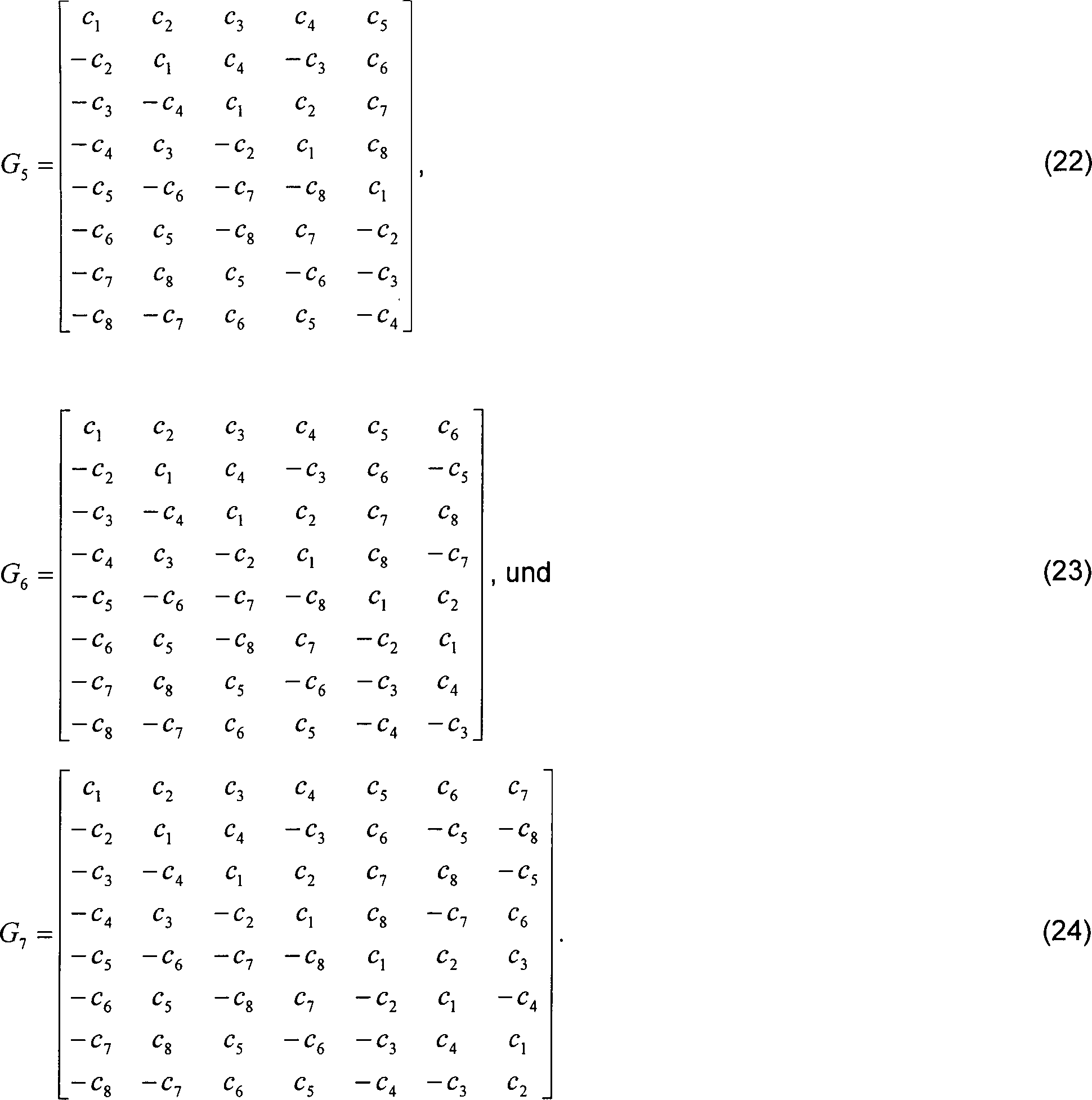
Tatsächlich kann
eine derartige Matrix für
das System der 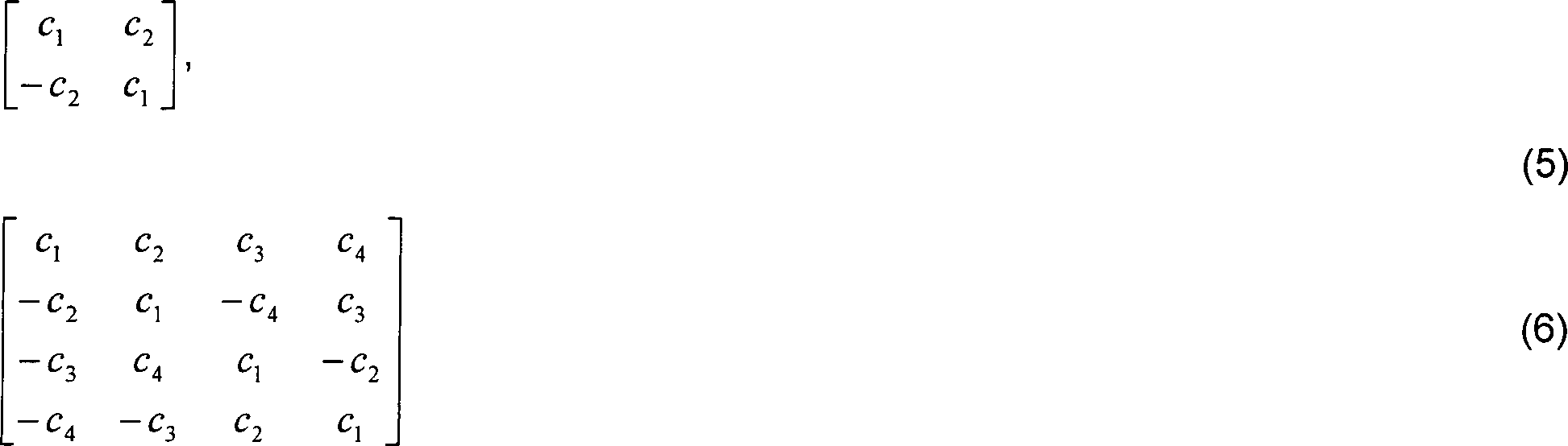
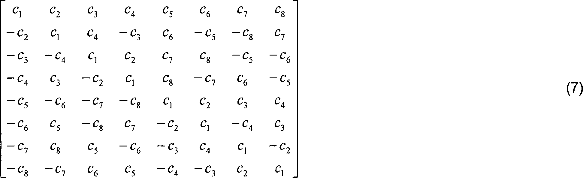
Das bedeutet zum Beispiel, dass, wenn ein Sender 8 Antennen verwendet, er einen Frame von 8 Bit akkumuliert und zu Beginn des nächsten Frames in dem ersten Zeitintervall die 8 Antennen die Bit c1, c2, c3, c4, c5, c6, c7, c8 (die erste Reihe von Symbolen) senden. Während des zweiten Zeitintervalls, senden die 8 Antennen die Bit –c2, c1, c4, –c3, c6, –c5, –c8, c7 (die zweite Reihe von Symbolen) usw.This means, for example, that if a transmitter uses 8 antennas, it will accumulate a frame of 8 bits and at the beginning of the next frame in the first time interval the 8 antennas will store the bits c 1 , c 2 , c 3 , c 4 , c 5 , c 6 , c 7 , c 8 (the first row of symbols). During the second time interval, the 8 antennas transmit bits -c 2 , c 1 , c 4 , -c 3 , c 6 , -c 5 , -c 8 , c 7 (the second row of symbols), etc.
Eine Durchsicht der obigen Matrizen ergibt, dass die Reihen lediglich Permutationen der ersten Reihe, mit möglichen unterschiedlichen Vorzeichen sind. Die Permutationen können durch εk(p) beschrieben werden, so dass εk(p) = q bedeutet, dass in der Reihe k das Symbol cp in der Spalte q erscheint. Die unterschiedlichen Vorzeichen können ausgedrückt werden, indem man das Vorzeichen von ci in der Reihe k durch δk(i) beschreibt.A review of the above matrices reveals that the rows are only permutations of the first row, with possible different signs. The permutations can be described by ε k (p), so that ε k (p) = q means that in the row k the symbol c p appears in the column q. The different signs can be expressed by describing the sign of c i in the row k by δ k (i).
Es
kann gezeigt werden, dass die Minimierung der Metrik der Gleichung
(4) äquivalent
zur Minimierung der folgenden Summe ist ![]()
![]()
Da
der Term![]()
![]()
![]()
![]()
![]()
![]()
Das ist eine sehr einfache Dekodierungsstrategie, die Diversität bereitstellt.The is a very simple decoding strategy that provides diversity.
Es gibt zwei Vorzüge bei der Bereitstellung von Sendediversität über orthogonale Ausgestaltungen.
- • Es gibt keinen Verlust bei der Bandbreite in dem Sinne, dass die orthogonalen Ausgestaltungen die maximal mögliche Senderate bei völliger Diversität bereitstellen.
- • Es gibt einen äußerst einfachen Maximum-Likelihood-Dekodierungsalgorithmus, der nur lineare Kombination an dem Empfänger verwendet. Die Einfachheit des Algorithmus stammt aus der Orthogonalität der Spalten der orthogonalen Ausgestaltung.
- There is no loss in bandwidth in the sense that the orthogonal designs provide the maximum possible transmission rate with complete diversity.
- There is a very simple maximum likelihood decoding algorithm that uses only linear combination at the receiver. The simplicity of the algorithm comes from the orthogonality of the columns of orthogonal design.
Die obigen Eigenschaften werden sogar bewahrt, falls eine lineare Verarbeitung an dem Sender zugelassen ist. Gemäß den hierin offenbarten Prinzipien wird deshalb die Definition orthogonaler Arrays aufgeweicht, um eine lineare Verarbeitung an dem Sender zu gestatten. Von verschiedenen Antennen gesendete Signale sind nun lineare Kombinationen von Konstellationssymbolen.The above properties are even preserved if linear processing is allowed on the transmitter. According to the principles disclosed herein Therefore, the definition of orthogonal arrays is softened to to allow linear processing at the transmitter. Of different Antenna transmitted signals are now linear combinations of constellation symbols.
Das Folgende definiert eine Hurwitz-Radon-Matrizenfamilie.The The following defines a Hurwitz-Radon template family.
Definition:
Ein Satz von n×n
reellen Matrizen {B1, B2,
..., Bk} wird eine Hurwitz-Radon-Matrizenfamilie der
Größe k genannt,
falls
Es ist von Radon gezeigt worden, dass, wenn n = 2ab ist, wobei b ungerade ist und a = 4c + d mit 0 ≤ d < 4 und 0 ≤ c ist, dann die Hurwitz-Radon-Familie von n×n Matrizen weniger als ρ(n) = 8c + 2d ≤ n Matrizen enthält (die maximale Anzahl von Mitgliedern in der Familie ist p(n) – 1). Eine Hurwitz-Radon-Familie, die n – 1 Matrizen enthält, existiert genau dann, wenn n = 2, 4 oder 8 ist.It has been shown by Radon that when n = 2 a b, where b is odd and a = 4c + d where 0 ≤ d <4 and 0 ≤ c, then the Hurwitz-Radon family of n × n Matrices containing less than ρ (n) = 8c + 2 d ≤ n matrices (the maximum number of members in the family is p (n) - 1). A Hurwitz-Radon family containing n - 1 matrices exists if and only if n = 2, 4 or 8.
Definition:
A sei eine p×q
Matrix mit den Termen aij und B sei eine
beliebige willkürliche
Matrix. Das Tensorprodukt A⊗B
ist gegeben durch 
Beweis:
Der Beweis erfolgt über
explizite Konstruktion. Ib soll die Einheitsmatrix
der Größe b bezeichnen.
Wir beachten zunächst,
dass, wenn n = 2ab mit ungeradem b ist,
dann folgt daraus, dass ρ(n)
= ρ(2a) ist, da ρ(n) unabhängig von b(ρ(n) = 8c + 2d)
ist. Außerdem
ist bei einer gegebenen Familie von 2a×2a ganzzahligen Hurwitz-Radon-Matrizen {A1, A2, ..., Ak} der Größe s = ρ(2a) – 1
der Satz {A1 ⊗ In,
A2 ⊗ Ib, ..., Ak ⊗ Ib} eine Hurwitz-Radon-Familie von n×n ganzzahligen
Matrizen der Größe ρ(n) – 1. In
Anbetracht dieser Beobachtung ist es ausreichend, das Lemma für n = 2a zu beweisen. Dafür können wir einen Satz von Hurwitz-Radon-Matrizen
wählen,
wie ![]()
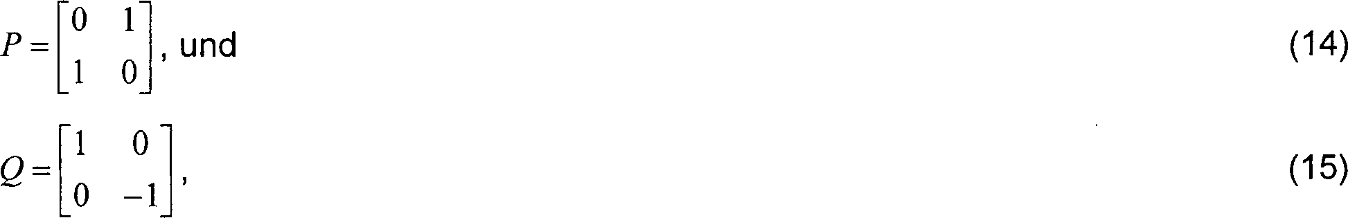
![]()
Man
kann beobachten, dass die Matrix R eine ganzzahlige Hurwitz-Radon-Familie
der Größe ρ(2) – 1 ist,
dass {R ⊗ I2, P ⊗ I2, ..., Q ⊗ I2}
eine ganzzahlige Hurwitz-Radon-Familie
der Größe p(22) – 1
ist und dass {I2 ⊗ R ⊗ I2,
I2 ⊗ P ⊗ R, Q ⊗ Q ⊗R, P⊗ Q ⊗ R, R ⊗ P ⊗ Q, R ⊗ P ⊗ P, R ⊗ Q ⊗ I2} eine ganzzahlige Hurwitz-Radon-Familie
der Größe ρ(23) – 1
ist. Ausgehend von dem obigen kann man einfach überprüfen, dass, falls {A1, A2, ..., Ak} eine ganzzahlige Hurwitz-Radon-Familie
von n×n
Matrizen ist, dann ist
Falls
zusätzlich
{L1, L2, ..., Lm} eine ganzzahlige Hurwitz-Radon-Familie
von k×k
Matrizen ist, dann ist
Bei einer Familie von ganzzahligen Hurwitz-Radon-Matrizen mit der für n = 23 konstruierten Größe ρ(23) – 1, mit Eingaben in dem Satz {–1, 0, 1}, ergibt die Gleichung (17) den Übergang von n1 zu n2. Unter Verwendung von (18) und mit k = n, und n = 2 erhalten wir den Übergang von n1 zu n3. Ähnlich erhalten wir mit k = n, und n = 4 den Übergang von n1 zu n3 und mit k = n1 und n = 8 erhalten wir den Übergang von n1 zu n5.For a family of integer Hurwitz-Radon matrices with the size ρ (2 3 ) -1, constructed for n = 2 3 , with entries in the set {-1, 0, 1}, equation (17) yields the transition from n 1 to n 2 . Using (18) and k = n, and n = 2, we get the transition from n 1 to n 3 . Similarly, with k = n, and n = 4, we get the transition from n 1 to n 3, and with k = n 1 and n = 8 we get the transition from n 1 to n 5 .
Der oben beschriebene einfache Maximum-Likelihood-Dekodierungsalgorithmus wird aufgrund der Orthogonalität der Spalten der Ausgestaltungsmatrix erzielt. Somit kann eine mehr verallgemeinerte Definition der orthogonalen Ausgestaltung toleriert werden. Dies erzeugt nicht nur neue und einfache Sendeschemen für eine beliebige Anzahl von Sendeantennen, sondern verallgemeinert auch die Hurwitz-Radon-Theorie auf nichtquadratische Matrizen.Of the above described simple maximum likelihood decoding algorithm is due to the orthogonality achieved the columns of the design matrix. Thus, one more generalized definition of orthogonal design tolerated become. This not only creates new and simple send schemes for any one Number of transmit antennas, but also generalizes the Hurwitz-Radon theory on non-square matrices.
Definition: Eine verallgemeinerte orthogonale Ausgestaltung G der Größe n ist eine p×n Matrix mit den Eingaben 0, ±x1, ±x2, ..., ±xk, so dass GTG = D eine diagonale Matrix mit der Diagonalen Dii, i = 1, 2, ..., n der Form (l i / 1x 2 / 1 + l i / 2x 2 / 2 + ... + l i / kx 2 / k) ist. Die Koeffizienten l i / 1, l i / 2, ..., l i / k sind positive ganze Zahlen. Die Rate von G ist R = k/p.Definition: A generalized orthogonal configuration G of size n is a p × n matrix with the inputs 0, ± x 1 , ± x 2 , ..., ± x k such that G T G = D is a diagonal diagonal matrix D ii , i = 1, 2, ..., n of the form (li / 1x 2/1 + li / 2x 2/2 + ... + li / kx 2 / k). The coefficients li / 1, li / 2, ..., li / k are positive integers. The rate of G is R = k / p.
Theorem: Eine p×n verallgemeinerte orthogonale Ausgestaltung E in den Variablen x1, x2, ..., xk existiert genau dann, wenn eine verallgemeinerte orthogonale Ausgestaltung G in denselben Variablen und derselben Größe existiert, so dass GTG = (x 2 / 1 + x 2 / 2 + ... + x 2 / k)I ist.Theorem: A p × n generalized orthogonal configuration E in the variables x 1 , x 2 , ..., x k exists if and only if a generalized orthogonal configuration G exists in the same variables and size, such that G T G = ( x 2/1 + x 2/2 + ... + x 2 / k) is I.
In Anbetracht des obigen Theorems, ohne Verlust der Allgemeinheit, kann man annehmen, dass eine beliebige p×n verallgemeinerte orthogonale Ausgestaltung G in den Variablen x1, x2, ..., xk die Gleichung GTG = (x 2 / 1 + x 2 / 2 + ... + x 2 / k)I erfüllt.In view of the above theorem, without loss of generality, we can assume that any p × n generalized orthogonal design G in the variables x1, x2, ..., x k, the equation G T G = (x 2/1 + x 2/2 + ... + x 2 / k) I satisfied.
Die obigen Ableitungen können für das Senden von Signalen von n Antennen unter Verwendung einer verallgemeinerten orthogonalen Ausgestaltung verwendet werden.The above derivations can for the Sending signals from n antennas using a generalized orthogonal design can be used.
Bei
Betrachtung einer Konstellation A der Größe 2b kann
ein Durchsatz von kb/p erreicht werden. In dem Zeitfenster 1 kommen
kb Bit an dem Codierer an, der die Konstellationssymbole c1, c2, ..., cn selektiert. Der Codierer besetzt die Matrix,
indem xi = ci gesetzt
wird, und zu den Zeitpunkten t = 1, 2, ..., p werden die Signale Gt1, Gt2, ..., Gtn gleichzeitig von den Antennen 1, 2, ...,
n gesendet. Das heißt,
die Ausgestaltung der Sendungsmatrix ist 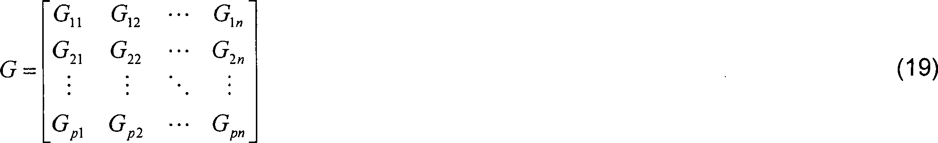
Somit werden kb Bit während jedes Frames von p Sendungen gesendet. Es kann gezeigt werden, dass die Diversität der Ordnung nm ist. Die Theorie der Raum-Zeit-Codierung besagt, dass es für eine Diversität der Ordnung nm möglich ist, b Bit pro Zeitfenster zu senden, und das ist das am besten Mögliche. Deshalb wird die Rate R für dieses Codierungsschema als kb/pb oder k/p definiert.Consequently be kb bit while every frame sent from p broadcasts. It can be shown that the diversity of order nm is. The theory of space-time coding states that it is for a diversity of order nm possible is to send b bits per slot, and that's the best Possible. Therefore, the rate R for this encoding scheme is defined as kb / pb or k / p.
Das folgende präsentiert einen Ansatz zur Konstruktion von Ausgestaltungen für lineare Verarbeitung hoher Rate mit niedriger Dekodierungskomplexität und voller Diversitätsordnung. Es wird als vorteilhaft erachtet, den Senderspeicher zu berücksichtigen, und das bedeutet, dass es bei gegebener Rate R und der Anzahl von Sendeantennen n vorteilhaft ist, die Anzahl der Zeitfenster in einem Frame p zu minimieren.The following presents an approach to the construction of embodiments for linear High rate processing with low decoding complexity and fuller Diversity order. It is considered advantageous to consider the station memory, and that means that given the rate R and the number of Transmit antenna n is advantageous, the number of time slots in one To minimize frame p.
Definition: Für ein gegebenes Paar (R, n), A(R, n) ist die minimale Anzahl p, so dass eine p×n verallgemeinerte Ausgestaltung mit der Rate von mindestens existiert. Falls keine derartige Ausgestaltung existiert, dann ist A(R, n) = ∞.Definition: For a given pair (R, n), A (R, n) is the minimum number p, so that a p × n generalized embodiment at the rate of at least exists. If no such configuration exists, then A (R, n) = ∞.
Der Wert von A(R, n) ist die grundlegende Frage der Theorie der verallgemeinerten Ausgestaltung. Der interessanteste Teil dieser Frage ist die Errechnung von A(1, n), weil die verallgemeinerten Ausgestaltungen der vollen Rate bandbreiteneffizient sind. Um die Frage zu behandeln, wird die folgende Konstruktion angeboten.Of the Value of A (R, n) is the fundamental question of the theory of generalized Design. The most interesting part of this question is the calculation of A (1, n), because the generalized embodiments of the full Rate are bandwidth efficient. To handle the question becomes the following construction offered.
Konstruktion I: Sei X = (x1, x2, ..., xp) und n < ρ(p). In der obigen Diskussion wurde eine Familie von ganzzahligen p×p Matrizen mit ρ(p) – 1 mit den Mitgliedern {A1, A2, ..., Aρ(p)-1} konstruiert (Lemma im Anschluss an Gleichung 12). Das heißt, die Mitglieder Ai sind in dem Satz {–1, 0, 1}. Sei A0 = I und man betrachte die p×n Matrix G, deren Spalte j gleich Aj-1XT für j = 1, 2, ... n ist. Die Hurwitz-Radon-Bedingungen implizieren, dass G eine verallgemeinerte orthogonale Ausgestaltung von voller Rate ist.Construction I: Let X = (x 1 , x 2 , ..., x p ) and n <ρ (p). In the above discussion, a family of integer p × p matrices with ρ (p) -1 was constructed with the members {A 1 , A 2 , ..., A ρ (p) -1 } (lemma following equation 12) ). That is, the members A i are in the set {-1, 0, 1}. Let A 0 = I and consider the p × n matrix G whose column j is equal to A j-1 X T for j = 1, 2, ... n. The Hurwitz-Radon conditions imply that G is a generalized orthogonal full rate design.
Aus dem obigen kann eine Anzahl von Fakten sichergestellt werden:
- – Der Wert A(1, n) ist die kleinere Zahl p, so dass n ≤ ρ(p) ist.
- – Der Wert von A(1, n) ist eine Potenz von 2 für beliebige n ≥ 2.
- – Der Wert von A(1, n) = min(24c+d) worin die Minimierung über den Satz {c,d|0 ≤ c,0 ≤ d < 4 und 8c + 2d ≥ n} gemacht wird.
- – A(1, 2) = 2, A(1, 3) = A(1, 4) = 4 und A(1, n) = 8 für 5 ≤ n ≤ 8.
- – Orthogonale Ausgestaltungen sind verzögerungsoptisch für n = 2, 4 und 8.
- – Für beliebige R ist A(R, n) < ∞.
- The value A (1, n) is the smaller number p such that n ≤ ρ (p).
- The value of A (1, n) is a power of 2 for any n ≥ 2.
- - The value of A (1, n) = min (2 4c + d ) where the minimization is made by the theorem {c, d | 0 ≤ c, 0 ≤ d <4 and 8c + 2 d ≥ n}.
- - A (1, 2) = 2, A (1, 3) = A (1, 4) = 4 and A (1, n) = 8 for 5 ≤ n ≤ 8.
- Orthogonal designs are delay optics for n = 2, 4 and 8.
- - For any R, A (R, n) <∞.
Das obige konstruiert explizit eine Hurwitz-Radon-Matrizenfamilie der Größe p mit ρ(p) Mitgliedern, so dass sämtliche Matrizen in der Familie Eingaben in dem Satz {1, 0, 1} aufweisen. Bei Vorliegen einer solchen Familie von Hurwitz-Radon-Matrizen der Größe p = A(1, n) können wir die Konstruktion I anwenden, um eine p×n verallgemeinerte orthogonale Ausgestaltung mit voller Rate bereitzustellen.The The above explicitly constructs a Hurwitz-Radon matrix family of Size p with ρ (p) members, so that all Matrices in the family have entries in the set {1, 0, 1}. In the presence of such a family of Hurwitz-Radon matrices the Size p = A (1, n) can we apply the construction I to a p × n generalized orthogonal To provide full rate design.
Diese
verallgemeinerte orthogonale Ausgestaltung mit voller Rate weist
Eingaben der Form ±c1, ±c2, ..., ±cp auf.
Somit sind für
einen Sender mit n ≤ 8
Sendeantennen die folgenden optimal verallgemeinerten Ausgestaltungen
der Rate Eins: 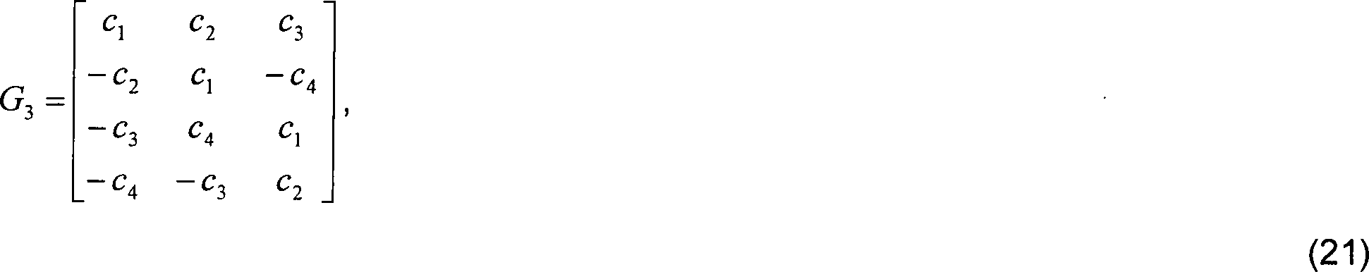
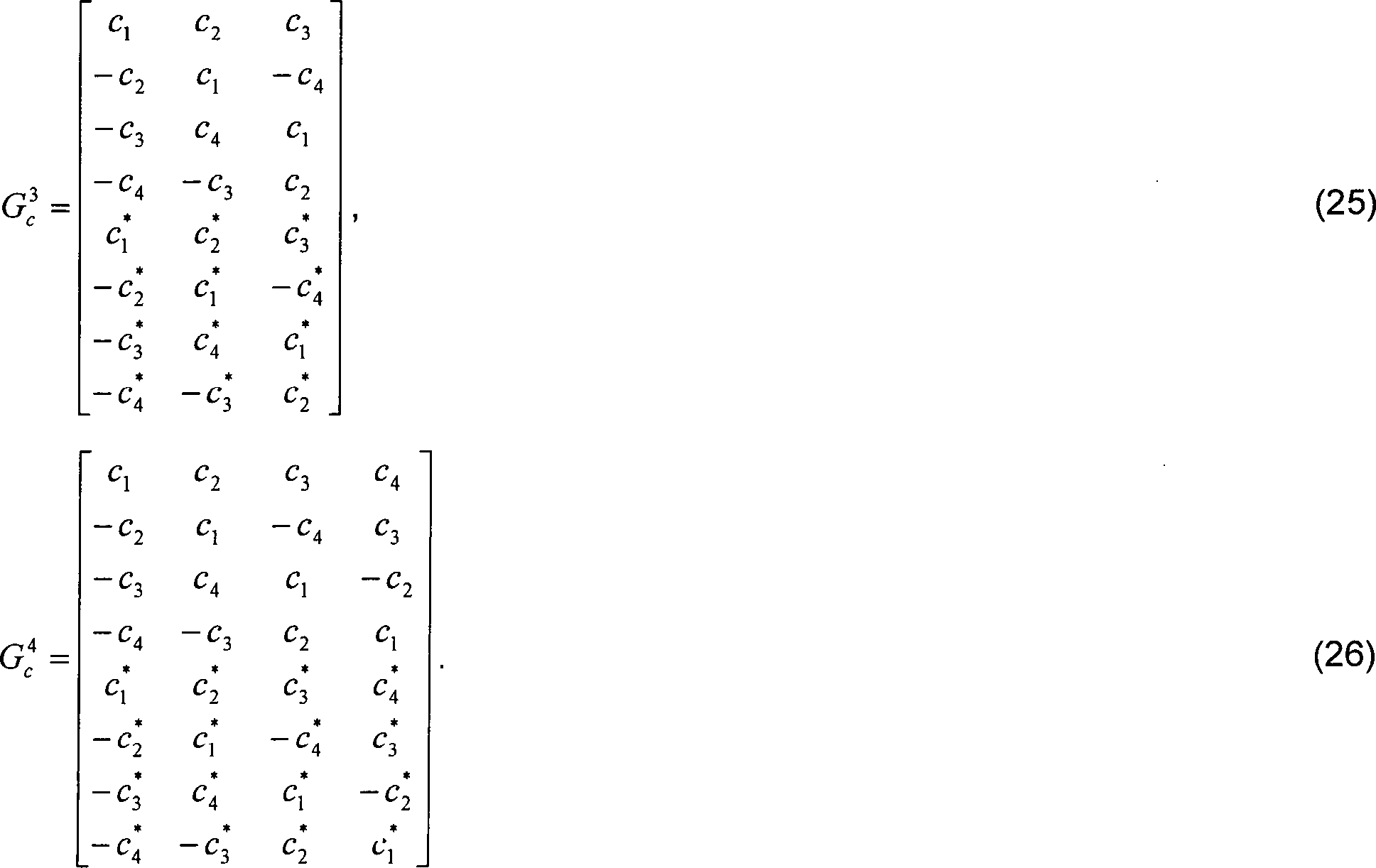
Die oben offenbarten einfachen Schemen der Sendediversität sind für eine reelle Signalkonstellation. Eine Ausgestaltung für eine komplexe Konstellation ist ebenfalls möglich. Eine komplexe orthogonale Ausgestaltung der Größe n, die hier umfasst ist, ist eine unitäre Matrix, deren Eingaben die Intermediate ±c1, ±c2, ...,±cn, ihre komplex Konjugierten ±c * / 1, ±c * / 2, ..., ±c * / n oder diese Intermediate multipliziert mit ±i sind, worin ist. Ohne Verlust der Allgemeinheit können wir die erste Zeile zu c1, c2, ..., cn wählen.The simple schemes of transmit diversity disclosed above are for a real signal constellation. An embodiment for a complex constellation is also possible. A complex orthogonal configuration of size n encompassed here is a unitary matrix whose inputs are the intermediates ± c 1 , ± c 2 , ..., ± c n , their complex conjugates ± c * / 1, ± c * / 2, ..., ± c * / n or these intermediates are multiplied by ± i, where is. Without loss of generality we can choose the first line to c 1 , c 2 , ..., c n .
Es
kann gezeigt werden, dass komplexe verallgemeinerte orthogonale
Ausgestaltungen mit halber Rate R = 0,5 existieren. Sie können konstruiert
werden, indem wie oben beschrieben eine Ausgestaltung für reelle
Symbole erzeugt wird, und die Zeilen wiederholt werden, mit der
Ausnahme, dass jedes Symbol durch dessen komplex Konjugierte ersetzt
wird. Unter der Vorgabe, dass eine Ausgestaltung für komplexe
Symbole verwirklicht werden muss, können wir, formaler ausgesagt,
jede komplexe Variable ci = c R / i + ic l / i worin
i = √–1 ist, durch
die reelle 2×2
Matrix![]()
![]()
Auf
diese Weise ist![]()
![]()
![]()
![]()
Diese Sendeschemen und deren Analoga für höhere Werte von n ergeben nicht nur volle Diversität, sondern ergeben 3 dB an zusätzlichem Codierungsgewinn gegenüber den nicht kodierten, aber sie verlieren die Hälfte der theoretischen Bandbreiteneffizienz.These Transmission schemes and their analogues for higher Values of n not only give full diversity but give 3 dB additional Coding gain over the not coded, but they lose half the theoretical bandwidth efficiency.
Einige Ausgestaltungen sind verfügbar, die eine höhere Rate als 0,5 bereitstellen. Das Folgende präsentiert Ausgestaltungen für die Rate 0,75 für n = 3 und n = 4.Some Designs are available the one higher Provide rate as 0.5. The following presents rate designs 0.75 for n = 3 and n = 4.
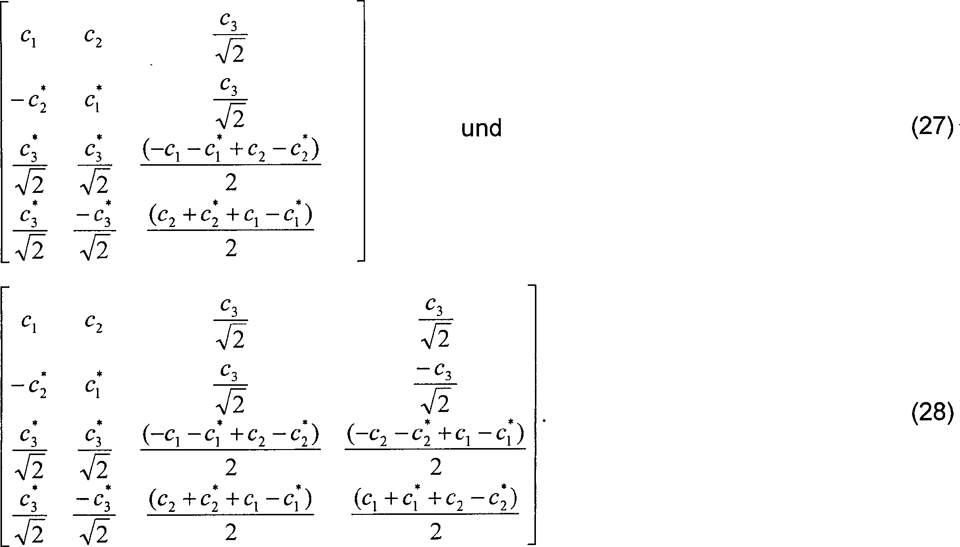
Die
Die
gesendeten Signale werden von dem Empfänger
Claims (2)
Applications Claiming Priority (5)
| Application Number | Priority Date | Filing Date | Title |
|---|---|---|---|
| US186907 | 1988-04-27 | ||
| US7661398P | 1998-03-03 | 1998-03-03 | |
| US76613P | 1998-03-03 | ||
| US09/186,907 US6088408A (en) | 1998-11-06 | 1998-11-06 | Decoding for generalized orthogonal designs for space-time codes for wireless communication |
| PCT/US1999/004187 WO1999045657A1 (en) | 1998-03-03 | 1999-02-26 | Decoding of space-time coded signals for wireless communication |
Publications (2)
| Publication Number | Publication Date |
|---|---|
| DE69936044D1 DE69936044D1 (en) | 2007-06-21 |
| DE69936044T2 true DE69936044T2 (en) | 2008-01-10 |
Family
ID=26758288
Family Applications (1)
| Application Number | Title | Priority Date | Filing Date |
|---|---|---|---|
| DE69936044T Expired - Lifetime DE69936044T2 (en) | 1998-03-03 | 1999-02-26 | DECODING SPACE-TIME-CODED SIGNALS FOR WIRELESS COMMUNICATION |
Country Status (8)
| Country | Link |
|---|---|
| EP (2) | EP2262123A3 (en) |
| JP (1) | JP4245802B2 (en) |
| KR (1) | KR100684483B1 (en) |
| CN (1) | CN1292175A (en) |
| BR (1) | BR9908389A (en) |
| CA (1) | CA2321618C (en) |
| DE (1) | DE69936044T2 (en) |
| WO (1) | WO1999045657A1 (en) |
Families Citing this family (17)
| Publication number | Priority date | Publication date | Assignee | Title |
|---|---|---|---|---|
| FI19992829A7 (en) | 1999-12-30 | 2001-07-01 | Nokia Networks Oy | Data transmission in a radio system from transmitter to receiver |
| EP1152548A1 (en) | 2000-05-05 | 2001-11-07 | Lucent Technologies Inc. | Increased data communication capacity of a high rate wireless network |
| US7068628B2 (en) | 2000-05-22 | 2006-06-27 | At&T Corp. | MIMO OFDM system |
| US6654928B1 (en) | 2000-07-20 | 2003-11-25 | Nokia Mobile Phones Limited | Hybrid dimensional, spherical space-time coding and decoding apparatus, and associated method, for a communication system |
| CN1561594A (en) * | 2002-06-07 | 2005-01-05 | 连宇通信有限公司 | An extended space-time block code encoding method and device |
| KR100630108B1 (en) | 2002-10-10 | 2006-09-27 | 삼성전자주식회사 | Transmitting and receiving apparatus for supporting transmission antenna diversity using space-time block code |
| EP1408623B1 (en) * | 2002-10-10 | 2010-12-15 | Samsung Electronics Co., Ltd. | Transmitting and receiving apparatus for supporting transmit antenna diversity using space-time block code. |
| KR100640349B1 (en) * | 2003-01-02 | 2006-10-30 | 삼성전자주식회사 | Transmission and reception device for wireless communication system having three transmitting antennas |
| KR100557085B1 (en) * | 2003-01-09 | 2006-03-03 | 삼성전자주식회사 | Receiver of wireless communication system using at least three transmit antennas |
| KR100605860B1 (en) * | 2003-01-09 | 2006-07-31 | 삼성전자주식회사 | Transmission apparatus and method in a wireless communication system using four transmitting antennas |
| FR2854995B1 (en) | 2003-05-14 | 2005-07-29 | Nortel Networks Ltd | SPECTRUM DISPLAY MODULATOR AND DEMODULATOR |
| GB2406759B (en) * | 2003-10-02 | 2006-06-07 | Toshiba Res Europ Ltd | Signal decoding methods and apparatus |
| GB2409384B (en) * | 2003-12-18 | 2005-11-30 | Toshiba Res Europ Ltd | Maximum likelihood sequence estimation equaliser |
| CN100346578C (en) * | 2004-01-07 | 2007-10-31 | 北京邮电大学 | Realizing method of space hour continuous phase modulating coder |
| WO2005117273A1 (en) | 2004-05-26 | 2005-12-08 | Nec Corporation | Spatially-multiplexed signal detecting method and time space iterative decoder using same |
| FR2873878A1 (en) | 2004-08-02 | 2006-02-03 | Nortel Networks Ltd | Encoded information radio transmission performing method for radio transmitter, involves transmitting sequences on respective physical information channels by utilizing transmission antennae |
| EP2087628B1 (en) * | 2006-11-14 | 2013-03-20 | Intel Corporation | Space-time decoder and methods for decoding alamouti-encoded signals in high-doppler environments |
Family Cites Families (3)
| Publication number | Priority date | Publication date | Assignee | Title |
|---|---|---|---|---|
| US5479448A (en) | 1992-03-31 | 1995-12-26 | At&T Corp. | Method and apparatus for providing antenna diversity |
| US6185258B1 (en) * | 1997-09-16 | 2001-02-06 | At&T Wireless Services Inc. | Transmitter diversity technique for wireless communications |
| US7422498B2 (en) | 2004-04-19 | 2008-09-09 | Burg Donald E | Ship with wave engulfing enhanced propulsors |
-
1999
- 1999-02-26 DE DE69936044T patent/DE69936044T2/en not_active Expired - Lifetime
- 1999-02-26 BR BR9908389-2A patent/BR9908389A/en not_active Application Discontinuation
- 1999-02-26 JP JP2000535103A patent/JP4245802B2/en not_active Expired - Fee Related
- 1999-02-26 KR KR1020007009707A patent/KR100684483B1/en not_active Expired - Fee Related
- 1999-02-26 EP EP10181645A patent/EP2262123A3/en not_active Withdrawn
- 1999-02-26 EP EP99908495A patent/EP1060575B1/en not_active Expired - Lifetime
- 1999-02-26 WO PCT/US1999/004187 patent/WO1999045657A1/en not_active Ceased
- 1999-02-26 CA CA002321618A patent/CA2321618C/en not_active Expired - Fee Related
- 1999-02-26 CN CN99803579A patent/CN1292175A/en active Pending
Also Published As
| Publication number | Publication date |
|---|---|
| KR100684483B1 (en) | 2007-02-22 |
| EP1060575A1 (en) | 2000-12-20 |
| CA2321618A1 (en) | 1999-09-10 |
| EP1060575B1 (en) | 2007-05-09 |
| JP4245802B2 (en) | 2009-04-02 |
| BR9908389A (en) | 2000-10-31 |
| DE69936044D1 (en) | 2007-06-21 |
| KR20010041534A (en) | 2001-05-25 |
| CA2321618C (en) | 2004-01-27 |
| EP2262123A2 (en) | 2010-12-15 |
| JP2002506316A (en) | 2002-02-26 |
| CN1292175A (en) | 2001-04-18 |
| WO1999045657A1 (en) | 1999-09-10 |
| EP2262123A3 (en) | 2011-01-19 |
Similar Documents
| Publication | Publication Date | Title |
|---|---|---|
| DE69936044T2 (en) | DECODING SPACE-TIME-CODED SIGNALS FOR WIRELESS COMMUNICATION | |
| DE60203234T2 (en) | Transfer rate control technology for MIMO systems with multiple transmit and receive antennas | |
| DE69815869T2 (en) | TRANSMITTER DIVERSITY TECHNOLOGY FOR WIRELESS COMMUNICATION | |
| DE60017836T2 (en) | Wireless multicast antenna system with combination of open-loop and closed-loop transmit diversity | |
| DE60219435T2 (en) | METHOD AND SYSTEM FOR ITERATIVELY ENCODING / DECODING A COST OF DIGITAL DATA BY MULTI-TIME CODED COMBINATIONS FOR MULTIPLE SENDING AND RECEIVING | |
| DE69833780T2 (en) | MAXIMUM PROBABILITY DETECTION OF CHAINED SPACE / TIME CODES FOR CORDLESS APPLICATIONS WITH TRANSMITTER DIVERSITY | |
| DE60035439T2 (en) | DIFFERENTIAL ROOM TIME BLOCK CODING | |
| DE69725995T2 (en) | SPATIAL SIGNAL PROCESSING FOR TRANSMISSION SYSTEMS | |
| DE60221766T2 (en) | Multiple antennas / multiple receivers Group antenna diversity system | |
| DE10254384B4 (en) | Bidirectional signal processing method for a MIMO system with a rate-adaptive adaptation of the data transmission rate | |
| DE60224672T2 (en) | TRANSMISSION METHOD AND DEVICE IN A RADIO COMMUNICATION NETWORK | |
| DE60101304T2 (en) | Diversity with an open control loop for systems with four transmit antennas | |
| DE60030620T2 (en) | Method for diversity reception and diversity receiver for OFDM signals | |
| DE60217706T2 (en) | STFBC CODING / DECODING DEVICE AND METHOD IN AN OFDM MOBILE COMMUNICATION SYSTEM | |
| DE69929788T2 (en) | METHOD AND DEVICE FOR DIVERSITY TRANSMISSION | |
| DE69737932T2 (en) | METHOD AND DEVICE FOR INTERFERENCE SUPPRESSION AND DOWN-LINE IRONING IN A CELLULAR RADIO COMMUNICATION SYSTEM | |
| DE602004013462T2 (en) | BROADCAST TRANSMISSION WITH SPATIAL SPREAD IN A MULTIPLE COMMUNICATION SYSTEM | |
| DE60033320T2 (en) | CHAINED SPACE-TIME CODING | |
| DE20218536U1 (en) | Multiple-input, multiple-output user device | |
| DE112021000831T5 (en) | Method for recovering discrete digital signals in noisy, congested wireless communication systems in the presence of hardware impairments | |
| DE602004001576T2 (en) | Method for transmitting data in a telecommunication system with at least one transmitter | |
| DE60300255T2 (en) | Pro data stream rate control via APP decoding | |
| DE60318291T2 (en) | Apparatus and method for transmitting and receiving coded signals with multiple antennas in mobile communication systems | |
| DE102007022262A1 (en) | Communication system and method for selecting its codewords | |
| DE69830458T2 (en) | Digital multi-carrier communication system with diversity reception |
Legal Events
| Date | Code | Title | Description |
|---|---|---|---|
| 8364 | No opposition during term of opposition |