DE69732226T2 - SPIN-FUSION IMPLANT AND INTRODUCTION AND INSPECTION TOOLS - Google Patents
SPIN-FUSION IMPLANT AND INTRODUCTION AND INSPECTION TOOLS Download PDFInfo
- Publication number
- DE69732226T2 DE69732226T2 DE69732226T DE69732226T DE69732226T2 DE 69732226 T2 DE69732226 T2 DE 69732226T2 DE 69732226 T DE69732226 T DE 69732226T DE 69732226 T DE69732226 T DE 69732226T DE 69732226 T2 DE69732226 T2 DE 69732226T2
- Authority
- DE
- Germany
- Prior art keywords
- bone
- fusion
- cap
- implant
- part according
- Prior art date
- Legal status (The legal status is an assumption and is not a legal conclusion. Google has not performed a legal analysis and makes no representation as to the accuracy of the status listed.)
- Expired - Fee Related
Links
Classifications
-
- A—HUMAN NECESSITIES
- A61—MEDICAL OR VETERINARY SCIENCE; HYGIENE
- A61F—FILTERS IMPLANTABLE INTO BLOOD VESSELS; PROSTHESES; DEVICES PROVIDING PATENCY TO, OR PREVENTING COLLAPSING OF, TUBULAR STRUCTURES OF THE BODY, e.g. STENTS; ORTHOPAEDIC, NURSING OR CONTRACEPTIVE DEVICES; FOMENTATION; TREATMENT OR PROTECTION OF EYES OR EARS; BANDAGES, DRESSINGS OR ABSORBENT PADS; FIRST-AID KITS
- A61F2/00—Filters implantable into blood vessels; Prostheses, i.e. artificial substitutes or replacements for parts of the body; Appliances for connecting them with the body; Devices providing patency to, or preventing collapsing of, tubular structures of the body, e.g. stents
- A61F2/02—Prostheses implantable into the body
- A61F2/30—Joints
- A61F2/44—Joints for the spine, e.g. vertebrae, spinal discs
- A61F2/4455—Joints for the spine, e.g. vertebrae, spinal discs for the fusion of spinal bodies, e.g. intervertebral fusion of adjacent spinal bodies, e.g. fusion cages
-
- A—HUMAN NECESSITIES
- A61—MEDICAL OR VETERINARY SCIENCE; HYGIENE
- A61B—DIAGNOSIS; SURGERY; IDENTIFICATION
- A61B17/00—Surgical instruments, devices or methods
- A61B17/16—Instruments for performing osteoclasis; Drills or chisels for bones; Trepans
- A61B17/1662—Instruments for performing osteoclasis; Drills or chisels for bones; Trepans for particular parts of the body
- A61B17/1671—Instruments for performing osteoclasis; Drills or chisels for bones; Trepans for particular parts of the body for the spine
-
- A—HUMAN NECESSITIES
- A61—MEDICAL OR VETERINARY SCIENCE; HYGIENE
- A61F—FILTERS IMPLANTABLE INTO BLOOD VESSELS; PROSTHESES; DEVICES PROVIDING PATENCY TO, OR PREVENTING COLLAPSING OF, TUBULAR STRUCTURES OF THE BODY, e.g. STENTS; ORTHOPAEDIC, NURSING OR CONTRACEPTIVE DEVICES; FOMENTATION; TREATMENT OR PROTECTION OF EYES OR EARS; BANDAGES, DRESSINGS OR ABSORBENT PADS; FIRST-AID KITS
- A61F2/00—Filters implantable into blood vessels; Prostheses, i.e. artificial substitutes or replacements for parts of the body; Appliances for connecting them with the body; Devices providing patency to, or preventing collapsing of, tubular structures of the body, e.g. stents
- A61F2/02—Prostheses implantable into the body
- A61F2/30—Joints
- A61F2/44—Joints for the spine, e.g. vertebrae, spinal discs
- A61F2/4455—Joints for the spine, e.g. vertebrae, spinal discs for the fusion of spinal bodies, e.g. intervertebral fusion of adjacent spinal bodies, e.g. fusion cages
- A61F2/446—Joints for the spine, e.g. vertebrae, spinal discs for the fusion of spinal bodies, e.g. intervertebral fusion of adjacent spinal bodies, e.g. fusion cages having a circular or elliptical cross-section substantially parallel to the axis of the spine, e.g. cylinders or frustocones
-
- A—HUMAN NECESSITIES
- A61—MEDICAL OR VETERINARY SCIENCE; HYGIENE
- A61F—FILTERS IMPLANTABLE INTO BLOOD VESSELS; PROSTHESES; DEVICES PROVIDING PATENCY TO, OR PREVENTING COLLAPSING OF, TUBULAR STRUCTURES OF THE BODY, e.g. STENTS; ORTHOPAEDIC, NURSING OR CONTRACEPTIVE DEVICES; FOMENTATION; TREATMENT OR PROTECTION OF EYES OR EARS; BANDAGES, DRESSINGS OR ABSORBENT PADS; FIRST-AID KITS
- A61F2/00—Filters implantable into blood vessels; Prostheses, i.e. artificial substitutes or replacements for parts of the body; Appliances for connecting them with the body; Devices providing patency to, or preventing collapsing of, tubular structures of the body, e.g. stents
- A61F2/02—Prostheses implantable into the body
- A61F2/30—Joints
- A61F2/46—Special tools for implanting artificial joints
- A61F2/4603—Special tools for implanting artificial joints for insertion or extraction of endoprosthetic joints or of accessories thereof
- A61F2/4611—Special tools for implanting artificial joints for insertion or extraction of endoprosthetic joints or of accessories thereof of spinal prostheses
-
- A—HUMAN NECESSITIES
- A61—MEDICAL OR VETERINARY SCIENCE; HYGIENE
- A61F—FILTERS IMPLANTABLE INTO BLOOD VESSELS; PROSTHESES; DEVICES PROVIDING PATENCY TO, OR PREVENTING COLLAPSING OF, TUBULAR STRUCTURES OF THE BODY, e.g. STENTS; ORTHOPAEDIC, NURSING OR CONTRACEPTIVE DEVICES; FOMENTATION; TREATMENT OR PROTECTION OF EYES OR EARS; BANDAGES, DRESSINGS OR ABSORBENT PADS; FIRST-AID KITS
- A61F2/00—Filters implantable into blood vessels; Prostheses, i.e. artificial substitutes or replacements for parts of the body; Appliances for connecting them with the body; Devices providing patency to, or preventing collapsing of, tubular structures of the body, e.g. stents
- A61F2/02—Prostheses implantable into the body
- A61F2/30—Joints
- A61F2/46—Special tools for implanting artificial joints
- A61F2/4637—Special tools for implanting artificial joints for connecting or disconnecting two parts of a prosthesis
-
- A—HUMAN NECESSITIES
- A61—MEDICAL OR VETERINARY SCIENCE; HYGIENE
- A61L—METHODS OR APPARATUS FOR STERILISING MATERIALS OR OBJECTS IN GENERAL; DISINFECTION, STERILISATION OR DEODORISATION OF AIR; CHEMICAL ASPECTS OF BANDAGES, DRESSINGS, ABSORBENT PADS OR SURGICAL ARTICLES; MATERIALS FOR BANDAGES, DRESSINGS, ABSORBENT PADS OR SURGICAL ARTICLES
- A61L27/00—Materials for grafts or prostheses or for coating grafts or prostheses
- A61L27/14—Macromolecular materials
- A61L27/22—Polypeptides or derivatives thereof, e.g. degradation products
- A61L27/227—Other specific proteins or polypeptides not covered by A61L27/222, A61L27/225 or A61L27/24
-
- A—HUMAN NECESSITIES
- A61—MEDICAL OR VETERINARY SCIENCE; HYGIENE
- A61L—METHODS OR APPARATUS FOR STERILISING MATERIALS OR OBJECTS IN GENERAL; DISINFECTION, STERILISATION OR DEODORISATION OF AIR; CHEMICAL ASPECTS OF BANDAGES, DRESSINGS, ABSORBENT PADS OR SURGICAL ARTICLES; MATERIALS FOR BANDAGES, DRESSINGS, ABSORBENT PADS OR SURGICAL ARTICLES
- A61L31/00—Materials for other surgical articles, e.g. stents, stent-grafts, shunts, surgical drapes, guide wires, materials for adhesion prevention, occluding devices, surgical gloves, tissue fixation devices
- A61L31/04—Macromolecular materials
- A61L31/043—Proteins; Polypeptides; Degradation products thereof
- A61L31/047—Other specific proteins or polypeptides not covered by A61L31/044 - A61L31/046
-
- A—HUMAN NECESSITIES
- A61—MEDICAL OR VETERINARY SCIENCE; HYGIENE
- A61B—DIAGNOSIS; SURGERY; IDENTIFICATION
- A61B17/00—Surgical instruments, devices or methods
- A61B17/56—Surgical instruments or methods for treatment of bones or joints; Devices specially adapted therefor
- A61B17/58—Surgical instruments or methods for treatment of bones or joints; Devices specially adapted therefor for osteosynthesis, e.g. bone plates, screws or setting implements
- A61B17/88—Osteosynthesis instruments; Methods or means for implanting or extracting internal or external fixation devices
- A61B17/8875—Screwdrivers, spanners or wrenches
- A61B17/8877—Screwdrivers, spanners or wrenches characterised by the cross-section of the driver bit
-
- A—HUMAN NECESSITIES
- A61—MEDICAL OR VETERINARY SCIENCE; HYGIENE
- A61B—DIAGNOSIS; SURGERY; IDENTIFICATION
- A61B17/00—Surgical instruments, devices or methods
- A61B17/56—Surgical instruments or methods for treatment of bones or joints; Devices specially adapted therefor
- A61B17/58—Surgical instruments or methods for treatment of bones or joints; Devices specially adapted therefor for osteosynthesis, e.g. bone plates, screws or setting implements
- A61B17/88—Osteosynthesis instruments; Methods or means for implanting or extracting internal or external fixation devices
- A61B17/8875—Screwdrivers, spanners or wrenches
- A61B17/8886—Screwdrivers, spanners or wrenches holding the screw head
- A61B17/8891—Screwdrivers, spanners or wrenches holding the screw head at its periphery
-
- A—HUMAN NECESSITIES
- A61—MEDICAL OR VETERINARY SCIENCE; HYGIENE
- A61F—FILTERS IMPLANTABLE INTO BLOOD VESSELS; PROSTHESES; DEVICES PROVIDING PATENCY TO, OR PREVENTING COLLAPSING OF, TUBULAR STRUCTURES OF THE BODY, e.g. STENTS; ORTHOPAEDIC, NURSING OR CONTRACEPTIVE DEVICES; FOMENTATION; TREATMENT OR PROTECTION OF EYES OR EARS; BANDAGES, DRESSINGS OR ABSORBENT PADS; FIRST-AID KITS
- A61F2/00—Filters implantable into blood vessels; Prostheses, i.e. artificial substitutes or replacements for parts of the body; Appliances for connecting them with the body; Devices providing patency to, or preventing collapsing of, tubular structures of the body, e.g. stents
- A61F2/02—Prostheses implantable into the body
- A61F2/30—Joints
- A61F2/30721—Accessories
- A61F2/30744—End caps, e.g. for closing an endoprosthetic cavity
-
- A—HUMAN NECESSITIES
- A61—MEDICAL OR VETERINARY SCIENCE; HYGIENE
- A61F—FILTERS IMPLANTABLE INTO BLOOD VESSELS; PROSTHESES; DEVICES PROVIDING PATENCY TO, OR PREVENTING COLLAPSING OF, TUBULAR STRUCTURES OF THE BODY, e.g. STENTS; ORTHOPAEDIC, NURSING OR CONTRACEPTIVE DEVICES; FOMENTATION; TREATMENT OR PROTECTION OF EYES OR EARS; BANDAGES, DRESSINGS OR ABSORBENT PADS; FIRST-AID KITS
- A61F2/00—Filters implantable into blood vessels; Prostheses, i.e. artificial substitutes or replacements for parts of the body; Appliances for connecting them with the body; Devices providing patency to, or preventing collapsing of, tubular structures of the body, e.g. stents
- A61F2/02—Prostheses implantable into the body
- A61F2/30—Joints
- A61F2/30767—Special external or bone-contacting surface, e.g. coating for improving bone ingrowth
-
- A—HUMAN NECESSITIES
- A61—MEDICAL OR VETERINARY SCIENCE; HYGIENE
- A61F—FILTERS IMPLANTABLE INTO BLOOD VESSELS; PROSTHESES; DEVICES PROVIDING PATENCY TO, OR PREVENTING COLLAPSING OF, TUBULAR STRUCTURES OF THE BODY, e.g. STENTS; ORTHOPAEDIC, NURSING OR CONTRACEPTIVE DEVICES; FOMENTATION; TREATMENT OR PROTECTION OF EYES OR EARS; BANDAGES, DRESSINGS OR ABSORBENT PADS; FIRST-AID KITS
- A61F2/00—Filters implantable into blood vessels; Prostheses, i.e. artificial substitutes or replacements for parts of the body; Appliances for connecting them with the body; Devices providing patency to, or preventing collapsing of, tubular structures of the body, e.g. stents
- A61F2/02—Prostheses implantable into the body
- A61F2/30—Joints
- A61F2/44—Joints for the spine, e.g. vertebrae, spinal discs
- A61F2/442—Intervertebral or spinal discs, e.g. resilient
-
- A—HUMAN NECESSITIES
- A61—MEDICAL OR VETERINARY SCIENCE; HYGIENE
- A61F—FILTERS IMPLANTABLE INTO BLOOD VESSELS; PROSTHESES; DEVICES PROVIDING PATENCY TO, OR PREVENTING COLLAPSING OF, TUBULAR STRUCTURES OF THE BODY, e.g. STENTS; ORTHOPAEDIC, NURSING OR CONTRACEPTIVE DEVICES; FOMENTATION; TREATMENT OR PROTECTION OF EYES OR EARS; BANDAGES, DRESSINGS OR ABSORBENT PADS; FIRST-AID KITS
- A61F2/00—Filters implantable into blood vessels; Prostheses, i.e. artificial substitutes or replacements for parts of the body; Appliances for connecting them with the body; Devices providing patency to, or preventing collapsing of, tubular structures of the body, e.g. stents
- A61F2/02—Prostheses implantable into the body
- A61F2/28—Bones
- A61F2002/2835—Bone graft implants for filling a bony defect or an endoprosthesis cavity, e.g. by synthetic material or biological material
-
- A—HUMAN NECESSITIES
- A61—MEDICAL OR VETERINARY SCIENCE; HYGIENE
- A61F—FILTERS IMPLANTABLE INTO BLOOD VESSELS; PROSTHESES; DEVICES PROVIDING PATENCY TO, OR PREVENTING COLLAPSING OF, TUBULAR STRUCTURES OF THE BODY, e.g. STENTS; ORTHOPAEDIC, NURSING OR CONTRACEPTIVE DEVICES; FOMENTATION; TREATMENT OR PROTECTION OF EYES OR EARS; BANDAGES, DRESSINGS OR ABSORBENT PADS; FIRST-AID KITS
- A61F2/00—Filters implantable into blood vessels; Prostheses, i.e. artificial substitutes or replacements for parts of the body; Appliances for connecting them with the body; Devices providing patency to, or preventing collapsing of, tubular structures of the body, e.g. stents
- A61F2/02—Prostheses implantable into the body
- A61F2/30—Joints
- A61F2002/30001—Additional features of subject-matter classified in A61F2/28, A61F2/30 and subgroups thereof
- A61F2002/30108—Shapes
- A61F2002/3011—Cross-sections or two-dimensional shapes
- A61F2002/30112—Rounded shapes, e.g. with rounded corners
- A61F2002/30136—Rounded shapes, e.g. with rounded corners undulated or wavy, e.g. serpentine-shaped or zigzag-shaped
-
- A—HUMAN NECESSITIES
- A61—MEDICAL OR VETERINARY SCIENCE; HYGIENE
- A61F—FILTERS IMPLANTABLE INTO BLOOD VESSELS; PROSTHESES; DEVICES PROVIDING PATENCY TO, OR PREVENTING COLLAPSING OF, TUBULAR STRUCTURES OF THE BODY, e.g. STENTS; ORTHOPAEDIC, NURSING OR CONTRACEPTIVE DEVICES; FOMENTATION; TREATMENT OR PROTECTION OF EYES OR EARS; BANDAGES, DRESSINGS OR ABSORBENT PADS; FIRST-AID KITS
- A61F2/00—Filters implantable into blood vessels; Prostheses, i.e. artificial substitutes or replacements for parts of the body; Appliances for connecting them with the body; Devices providing patency to, or preventing collapsing of, tubular structures of the body, e.g. stents
- A61F2/02—Prostheses implantable into the body
- A61F2/30—Joints
- A61F2002/30001—Additional features of subject-matter classified in A61F2/28, A61F2/30 and subgroups thereof
- A61F2002/30108—Shapes
- A61F2002/3011—Cross-sections or two-dimensional shapes
- A61F2002/30138—Convex polygonal shapes
- A61F2002/30143—Convex polygonal shapes hexagonal
-
- A—HUMAN NECESSITIES
- A61—MEDICAL OR VETERINARY SCIENCE; HYGIENE
- A61F—FILTERS IMPLANTABLE INTO BLOOD VESSELS; PROSTHESES; DEVICES PROVIDING PATENCY TO, OR PREVENTING COLLAPSING OF, TUBULAR STRUCTURES OF THE BODY, e.g. STENTS; ORTHOPAEDIC, NURSING OR CONTRACEPTIVE DEVICES; FOMENTATION; TREATMENT OR PROTECTION OF EYES OR EARS; BANDAGES, DRESSINGS OR ABSORBENT PADS; FIRST-AID KITS
- A61F2/00—Filters implantable into blood vessels; Prostheses, i.e. artificial substitutes or replacements for parts of the body; Appliances for connecting them with the body; Devices providing patency to, or preventing collapsing of, tubular structures of the body, e.g. stents
- A61F2/02—Prostheses implantable into the body
- A61F2/30—Joints
- A61F2002/30001—Additional features of subject-matter classified in A61F2/28, A61F2/30 and subgroups thereof
- A61F2002/30108—Shapes
- A61F2002/3011—Cross-sections or two-dimensional shapes
- A61F2002/30138—Convex polygonal shapes
- A61F2002/30153—Convex polygonal shapes rectangular
-
- A—HUMAN NECESSITIES
- A61—MEDICAL OR VETERINARY SCIENCE; HYGIENE
- A61F—FILTERS IMPLANTABLE INTO BLOOD VESSELS; PROSTHESES; DEVICES PROVIDING PATENCY TO, OR PREVENTING COLLAPSING OF, TUBULAR STRUCTURES OF THE BODY, e.g. STENTS; ORTHOPAEDIC, NURSING OR CONTRACEPTIVE DEVICES; FOMENTATION; TREATMENT OR PROTECTION OF EYES OR EARS; BANDAGES, DRESSINGS OR ABSORBENT PADS; FIRST-AID KITS
- A61F2/00—Filters implantable into blood vessels; Prostheses, i.e. artificial substitutes or replacements for parts of the body; Appliances for connecting them with the body; Devices providing patency to, or preventing collapsing of, tubular structures of the body, e.g. stents
- A61F2/02—Prostheses implantable into the body
- A61F2/30—Joints
- A61F2002/30001—Additional features of subject-matter classified in A61F2/28, A61F2/30 and subgroups thereof
- A61F2002/30108—Shapes
- A61F2002/3011—Cross-sections or two-dimensional shapes
- A61F2002/30138—Convex polygonal shapes
- A61F2002/30158—Convex polygonal shapes trapezoidal
-
- A—HUMAN NECESSITIES
- A61—MEDICAL OR VETERINARY SCIENCE; HYGIENE
- A61F—FILTERS IMPLANTABLE INTO BLOOD VESSELS; PROSTHESES; DEVICES PROVIDING PATENCY TO, OR PREVENTING COLLAPSING OF, TUBULAR STRUCTURES OF THE BODY, e.g. STENTS; ORTHOPAEDIC, NURSING OR CONTRACEPTIVE DEVICES; FOMENTATION; TREATMENT OR PROTECTION OF EYES OR EARS; BANDAGES, DRESSINGS OR ABSORBENT PADS; FIRST-AID KITS
- A61F2/00—Filters implantable into blood vessels; Prostheses, i.e. artificial substitutes or replacements for parts of the body; Appliances for connecting them with the body; Devices providing patency to, or preventing collapsing of, tubular structures of the body, e.g. stents
- A61F2/02—Prostheses implantable into the body
- A61F2/30—Joints
- A61F2002/30001—Additional features of subject-matter classified in A61F2/28, A61F2/30 and subgroups thereof
- A61F2002/30108—Shapes
- A61F2002/30199—Three-dimensional shapes
- A61F2002/30205—Three-dimensional shapes conical
- A61F2002/3021—Three-dimensional shapes conical frustoconical
-
- A—HUMAN NECESSITIES
- A61—MEDICAL OR VETERINARY SCIENCE; HYGIENE
- A61F—FILTERS IMPLANTABLE INTO BLOOD VESSELS; PROSTHESES; DEVICES PROVIDING PATENCY TO, OR PREVENTING COLLAPSING OF, TUBULAR STRUCTURES OF THE BODY, e.g. STENTS; ORTHOPAEDIC, NURSING OR CONTRACEPTIVE DEVICES; FOMENTATION; TREATMENT OR PROTECTION OF EYES OR EARS; BANDAGES, DRESSINGS OR ABSORBENT PADS; FIRST-AID KITS
- A61F2/00—Filters implantable into blood vessels; Prostheses, i.e. artificial substitutes or replacements for parts of the body; Appliances for connecting them with the body; Devices providing patency to, or preventing collapsing of, tubular structures of the body, e.g. stents
- A61F2/02—Prostheses implantable into the body
- A61F2/30—Joints
- A61F2002/30001—Additional features of subject-matter classified in A61F2/28, A61F2/30 and subgroups thereof
- A61F2002/30108—Shapes
- A61F2002/30199—Three-dimensional shapes
- A61F2002/30205—Three-dimensional shapes conical
- A61F2002/30217—Three-dimensional shapes conical hollow cones, e.g. tubular-like cones
-
- A—HUMAN NECESSITIES
- A61—MEDICAL OR VETERINARY SCIENCE; HYGIENE
- A61F—FILTERS IMPLANTABLE INTO BLOOD VESSELS; PROSTHESES; DEVICES PROVIDING PATENCY TO, OR PREVENTING COLLAPSING OF, TUBULAR STRUCTURES OF THE BODY, e.g. STENTS; ORTHOPAEDIC, NURSING OR CONTRACEPTIVE DEVICES; FOMENTATION; TREATMENT OR PROTECTION OF EYES OR EARS; BANDAGES, DRESSINGS OR ABSORBENT PADS; FIRST-AID KITS
- A61F2/00—Filters implantable into blood vessels; Prostheses, i.e. artificial substitutes or replacements for parts of the body; Appliances for connecting them with the body; Devices providing patency to, or preventing collapsing of, tubular structures of the body, e.g. stents
- A61F2/02—Prostheses implantable into the body
- A61F2/30—Joints
- A61F2002/30001—Additional features of subject-matter classified in A61F2/28, A61F2/30 and subgroups thereof
- A61F2002/30316—The prosthesis having different structural features at different locations within the same prosthesis; Connections between prosthetic parts; Special structural features of bone or joint prostheses not otherwise provided for
- A61F2002/30329—Connections or couplings between prosthetic parts, e.g. between modular parts; Connecting elements
- A61F2002/30476—Connections or couplings between prosthetic parts, e.g. between modular parts; Connecting elements locked by an additional locking mechanism
- A61F2002/305—Snap connection
-
- A—HUMAN NECESSITIES
- A61—MEDICAL OR VETERINARY SCIENCE; HYGIENE
- A61F—FILTERS IMPLANTABLE INTO BLOOD VESSELS; PROSTHESES; DEVICES PROVIDING PATENCY TO, OR PREVENTING COLLAPSING OF, TUBULAR STRUCTURES OF THE BODY, e.g. STENTS; ORTHOPAEDIC, NURSING OR CONTRACEPTIVE DEVICES; FOMENTATION; TREATMENT OR PROTECTION OF EYES OR EARS; BANDAGES, DRESSINGS OR ABSORBENT PADS; FIRST-AID KITS
- A61F2/00—Filters implantable into blood vessels; Prostheses, i.e. artificial substitutes or replacements for parts of the body; Appliances for connecting them with the body; Devices providing patency to, or preventing collapsing of, tubular structures of the body, e.g. stents
- A61F2/02—Prostheses implantable into the body
- A61F2/30—Joints
- A61F2002/30001—Additional features of subject-matter classified in A61F2/28, A61F2/30 and subgroups thereof
- A61F2002/30316—The prosthesis having different structural features at different locations within the same prosthesis; Connections between prosthetic parts; Special structural features of bone or joint prostheses not otherwise provided for
- A61F2002/30535—Special structural features of bone or joint prostheses not otherwise provided for
- A61F2002/30593—Special structural features of bone or joint prostheses not otherwise provided for hollow
-
- A—HUMAN NECESSITIES
- A61—MEDICAL OR VETERINARY SCIENCE; HYGIENE
- A61F—FILTERS IMPLANTABLE INTO BLOOD VESSELS; PROSTHESES; DEVICES PROVIDING PATENCY TO, OR PREVENTING COLLAPSING OF, TUBULAR STRUCTURES OF THE BODY, e.g. STENTS; ORTHOPAEDIC, NURSING OR CONTRACEPTIVE DEVICES; FOMENTATION; TREATMENT OR PROTECTION OF EYES OR EARS; BANDAGES, DRESSINGS OR ABSORBENT PADS; FIRST-AID KITS
- A61F2/00—Filters implantable into blood vessels; Prostheses, i.e. artificial substitutes or replacements for parts of the body; Appliances for connecting them with the body; Devices providing patency to, or preventing collapsing of, tubular structures of the body, e.g. stents
- A61F2/02—Prostheses implantable into the body
- A61F2/30—Joints
- A61F2/30767—Special external or bone-contacting surface, e.g. coating for improving bone ingrowth
- A61F2/30771—Special external or bone-contacting surface, e.g. coating for improving bone ingrowth applied in original prostheses, e.g. holes or grooves
- A61F2002/30772—Apertures or holes, e.g. of circular cross section
- A61F2002/30774—Apertures or holes, e.g. of circular cross section internally-threaded
-
- A—HUMAN NECESSITIES
- A61—MEDICAL OR VETERINARY SCIENCE; HYGIENE
- A61F—FILTERS IMPLANTABLE INTO BLOOD VESSELS; PROSTHESES; DEVICES PROVIDING PATENCY TO, OR PREVENTING COLLAPSING OF, TUBULAR STRUCTURES OF THE BODY, e.g. STENTS; ORTHOPAEDIC, NURSING OR CONTRACEPTIVE DEVICES; FOMENTATION; TREATMENT OR PROTECTION OF EYES OR EARS; BANDAGES, DRESSINGS OR ABSORBENT PADS; FIRST-AID KITS
- A61F2/00—Filters implantable into blood vessels; Prostheses, i.e. artificial substitutes or replacements for parts of the body; Appliances for connecting them with the body; Devices providing patency to, or preventing collapsing of, tubular structures of the body, e.g. stents
- A61F2/02—Prostheses implantable into the body
- A61F2/30—Joints
- A61F2/30767—Special external or bone-contacting surface, e.g. coating for improving bone ingrowth
- A61F2/30771—Special external or bone-contacting surface, e.g. coating for improving bone ingrowth applied in original prostheses, e.g. holes or grooves
- A61F2002/30772—Apertures or holes, e.g. of circular cross section
- A61F2002/30777—Oblong apertures
-
- A—HUMAN NECESSITIES
- A61—MEDICAL OR VETERINARY SCIENCE; HYGIENE
- A61F—FILTERS IMPLANTABLE INTO BLOOD VESSELS; PROSTHESES; DEVICES PROVIDING PATENCY TO, OR PREVENTING COLLAPSING OF, TUBULAR STRUCTURES OF THE BODY, e.g. STENTS; ORTHOPAEDIC, NURSING OR CONTRACEPTIVE DEVICES; FOMENTATION; TREATMENT OR PROTECTION OF EYES OR EARS; BANDAGES, DRESSINGS OR ABSORBENT PADS; FIRST-AID KITS
- A61F2/00—Filters implantable into blood vessels; Prostheses, i.e. artificial substitutes or replacements for parts of the body; Appliances for connecting them with the body; Devices providing patency to, or preventing collapsing of, tubular structures of the body, e.g. stents
- A61F2/02—Prostheses implantable into the body
- A61F2/30—Joints
- A61F2/30767—Special external or bone-contacting surface, e.g. coating for improving bone ingrowth
- A61F2/30771—Special external or bone-contacting surface, e.g. coating for improving bone ingrowth applied in original prostheses, e.g. holes or grooves
- A61F2002/30772—Apertures or holes, e.g. of circular cross section
- A61F2002/30784—Plurality of holes
- A61F2002/30785—Plurality of holes parallel
-
- A—HUMAN NECESSITIES
- A61—MEDICAL OR VETERINARY SCIENCE; HYGIENE
- A61F—FILTERS IMPLANTABLE INTO BLOOD VESSELS; PROSTHESES; DEVICES PROVIDING PATENCY TO, OR PREVENTING COLLAPSING OF, TUBULAR STRUCTURES OF THE BODY, e.g. STENTS; ORTHOPAEDIC, NURSING OR CONTRACEPTIVE DEVICES; FOMENTATION; TREATMENT OR PROTECTION OF EYES OR EARS; BANDAGES, DRESSINGS OR ABSORBENT PADS; FIRST-AID KITS
- A61F2/00—Filters implantable into blood vessels; Prostheses, i.e. artificial substitutes or replacements for parts of the body; Appliances for connecting them with the body; Devices providing patency to, or preventing collapsing of, tubular structures of the body, e.g. stents
- A61F2/02—Prostheses implantable into the body
- A61F2/30—Joints
- A61F2/30767—Special external or bone-contacting surface, e.g. coating for improving bone ingrowth
- A61F2/30771—Special external or bone-contacting surface, e.g. coating for improving bone ingrowth applied in original prostheses, e.g. holes or grooves
- A61F2002/3082—Grooves
-
- A—HUMAN NECESSITIES
- A61—MEDICAL OR VETERINARY SCIENCE; HYGIENE
- A61F—FILTERS IMPLANTABLE INTO BLOOD VESSELS; PROSTHESES; DEVICES PROVIDING PATENCY TO, OR PREVENTING COLLAPSING OF, TUBULAR STRUCTURES OF THE BODY, e.g. STENTS; ORTHOPAEDIC, NURSING OR CONTRACEPTIVE DEVICES; FOMENTATION; TREATMENT OR PROTECTION OF EYES OR EARS; BANDAGES, DRESSINGS OR ABSORBENT PADS; FIRST-AID KITS
- A61F2/00—Filters implantable into blood vessels; Prostheses, i.e. artificial substitutes or replacements for parts of the body; Appliances for connecting them with the body; Devices providing patency to, or preventing collapsing of, tubular structures of the body, e.g. stents
- A61F2/02—Prostheses implantable into the body
- A61F2/30—Joints
- A61F2/30767—Special external or bone-contacting surface, e.g. coating for improving bone ingrowth
- A61F2/30771—Special external or bone-contacting surface, e.g. coating for improving bone ingrowth applied in original prostheses, e.g. holes or grooves
- A61F2002/3085—Special external or bone-contacting surface, e.g. coating for improving bone ingrowth applied in original prostheses, e.g. holes or grooves with a threaded, e.g. self-tapping, bone-engaging surface, e.g. external surface
- A61F2002/30858—Threads interrupted by grooves or sidewalls, e.g. flat sidewalls
-
- A—HUMAN NECESSITIES
- A61—MEDICAL OR VETERINARY SCIENCE; HYGIENE
- A61F—FILTERS IMPLANTABLE INTO BLOOD VESSELS; PROSTHESES; DEVICES PROVIDING PATENCY TO, OR PREVENTING COLLAPSING OF, TUBULAR STRUCTURES OF THE BODY, e.g. STENTS; ORTHOPAEDIC, NURSING OR CONTRACEPTIVE DEVICES; FOMENTATION; TREATMENT OR PROTECTION OF EYES OR EARS; BANDAGES, DRESSINGS OR ABSORBENT PADS; FIRST-AID KITS
- A61F2/00—Filters implantable into blood vessels; Prostheses, i.e. artificial substitutes or replacements for parts of the body; Appliances for connecting them with the body; Devices providing patency to, or preventing collapsing of, tubular structures of the body, e.g. stents
- A61F2/02—Prostheses implantable into the body
- A61F2/30—Joints
- A61F2/30767—Special external or bone-contacting surface, e.g. coating for improving bone ingrowth
- A61F2/30771—Special external or bone-contacting surface, e.g. coating for improving bone ingrowth applied in original prostheses, e.g. holes or grooves
- A61F2002/3085—Special external or bone-contacting surface, e.g. coating for improving bone ingrowth applied in original prostheses, e.g. holes or grooves with a threaded, e.g. self-tapping, bone-engaging surface, e.g. external surface
- A61F2002/30873—Threadings machined on non-cylindrical external surfaces
-
- A—HUMAN NECESSITIES
- A61—MEDICAL OR VETERINARY SCIENCE; HYGIENE
- A61F—FILTERS IMPLANTABLE INTO BLOOD VESSELS; PROSTHESES; DEVICES PROVIDING PATENCY TO, OR PREVENTING COLLAPSING OF, TUBULAR STRUCTURES OF THE BODY, e.g. STENTS; ORTHOPAEDIC, NURSING OR CONTRACEPTIVE DEVICES; FOMENTATION; TREATMENT OR PROTECTION OF EYES OR EARS; BANDAGES, DRESSINGS OR ABSORBENT PADS; FIRST-AID KITS
- A61F2/00—Filters implantable into blood vessels; Prostheses, i.e. artificial substitutes or replacements for parts of the body; Appliances for connecting them with the body; Devices providing patency to, or preventing collapsing of, tubular structures of the body, e.g. stents
- A61F2/02—Prostheses implantable into the body
- A61F2/30—Joints
- A61F2/44—Joints for the spine, e.g. vertebrae, spinal discs
- A61F2002/448—Joints for the spine, e.g. vertebrae, spinal discs comprising multiple adjacent spinal implants within the same intervertebral space or within the same vertebra, e.g. comprising two adjacent spinal implants
-
- A—HUMAN NECESSITIES
- A61—MEDICAL OR VETERINARY SCIENCE; HYGIENE
- A61F—FILTERS IMPLANTABLE INTO BLOOD VESSELS; PROSTHESES; DEVICES PROVIDING PATENCY TO, OR PREVENTING COLLAPSING OF, TUBULAR STRUCTURES OF THE BODY, e.g. STENTS; ORTHOPAEDIC, NURSING OR CONTRACEPTIVE DEVICES; FOMENTATION; TREATMENT OR PROTECTION OF EYES OR EARS; BANDAGES, DRESSINGS OR ABSORBENT PADS; FIRST-AID KITS
- A61F2/00—Filters implantable into blood vessels; Prostheses, i.e. artificial substitutes or replacements for parts of the body; Appliances for connecting them with the body; Devices providing patency to, or preventing collapsing of, tubular structures of the body, e.g. stents
- A61F2/02—Prostheses implantable into the body
- A61F2/30—Joints
- A61F2/46—Special tools for implanting artificial joints
- A61F2/4603—Special tools for implanting artificial joints for insertion or extraction of endoprosthetic joints or of accessories thereof
- A61F2002/4625—Special tools for implanting artificial joints for insertion or extraction of endoprosthetic joints or of accessories thereof with relative movement between parts of the instrument during use
- A61F2002/4627—Special tools for implanting artificial joints for insertion or extraction of endoprosthetic joints or of accessories thereof with relative movement between parts of the instrument during use with linear motion along or rotating motion about the instrument axis or the implantation direction, e.g. telescopic, along a guiding rod, screwing inside the instrument
-
- A—HUMAN NECESSITIES
- A61—MEDICAL OR VETERINARY SCIENCE; HYGIENE
- A61F—FILTERS IMPLANTABLE INTO BLOOD VESSELS; PROSTHESES; DEVICES PROVIDING PATENCY TO, OR PREVENTING COLLAPSING OF, TUBULAR STRUCTURES OF THE BODY, e.g. STENTS; ORTHOPAEDIC, NURSING OR CONTRACEPTIVE DEVICES; FOMENTATION; TREATMENT OR PROTECTION OF EYES OR EARS; BANDAGES, DRESSINGS OR ABSORBENT PADS; FIRST-AID KITS
- A61F2/00—Filters implantable into blood vessels; Prostheses, i.e. artificial substitutes or replacements for parts of the body; Appliances for connecting them with the body; Devices providing patency to, or preventing collapsing of, tubular structures of the body, e.g. stents
- A61F2/02—Prostheses implantable into the body
- A61F2/30—Joints
- A61F2/46—Special tools for implanting artificial joints
- A61F2/4637—Special tools for implanting artificial joints for connecting or disconnecting two parts of a prosthesis
- A61F2002/4641—Special tools for implanting artificial joints for connecting or disconnecting two parts of a prosthesis for disconnecting
-
- A—HUMAN NECESSITIES
- A61—MEDICAL OR VETERINARY SCIENCE; HYGIENE
- A61F—FILTERS IMPLANTABLE INTO BLOOD VESSELS; PROSTHESES; DEVICES PROVIDING PATENCY TO, OR PREVENTING COLLAPSING OF, TUBULAR STRUCTURES OF THE BODY, e.g. STENTS; ORTHOPAEDIC, NURSING OR CONTRACEPTIVE DEVICES; FOMENTATION; TREATMENT OR PROTECTION OF EYES OR EARS; BANDAGES, DRESSINGS OR ABSORBENT PADS; FIRST-AID KITS
- A61F2220/00—Fixations or connections for prostheses classified in groups A61F2/00 - A61F2/26 or A61F2/82 or A61F9/00 or A61F11/00 or subgroups thereof
- A61F2220/0025—Connections or couplings between prosthetic parts, e.g. between modular parts; Connecting elements
-
- A—HUMAN NECESSITIES
- A61—MEDICAL OR VETERINARY SCIENCE; HYGIENE
- A61F—FILTERS IMPLANTABLE INTO BLOOD VESSELS; PROSTHESES; DEVICES PROVIDING PATENCY TO, OR PREVENTING COLLAPSING OF, TUBULAR STRUCTURES OF THE BODY, e.g. STENTS; ORTHOPAEDIC, NURSING OR CONTRACEPTIVE DEVICES; FOMENTATION; TREATMENT OR PROTECTION OF EYES OR EARS; BANDAGES, DRESSINGS OR ABSORBENT PADS; FIRST-AID KITS
- A61F2230/00—Geometry of prostheses classified in groups A61F2/00 - A61F2/26 or A61F2/82 or A61F9/00 or A61F11/00 or subgroups thereof
- A61F2230/0002—Two-dimensional shapes, e.g. cross-sections
- A61F2230/0004—Rounded shapes, e.g. with rounded corners
-
- A—HUMAN NECESSITIES
- A61—MEDICAL OR VETERINARY SCIENCE; HYGIENE
- A61F—FILTERS IMPLANTABLE INTO BLOOD VESSELS; PROSTHESES; DEVICES PROVIDING PATENCY TO, OR PREVENTING COLLAPSING OF, TUBULAR STRUCTURES OF THE BODY, e.g. STENTS; ORTHOPAEDIC, NURSING OR CONTRACEPTIVE DEVICES; FOMENTATION; TREATMENT OR PROTECTION OF EYES OR EARS; BANDAGES, DRESSINGS OR ABSORBENT PADS; FIRST-AID KITS
- A61F2230/00—Geometry of prostheses classified in groups A61F2/00 - A61F2/26 or A61F2/82 or A61F9/00 or A61F11/00 or subgroups thereof
- A61F2230/0002—Two-dimensional shapes, e.g. cross-sections
- A61F2230/0017—Angular shapes
- A61F2230/0019—Angular shapes rectangular
-
- A—HUMAN NECESSITIES
- A61—MEDICAL OR VETERINARY SCIENCE; HYGIENE
- A61F—FILTERS IMPLANTABLE INTO BLOOD VESSELS; PROSTHESES; DEVICES PROVIDING PATENCY TO, OR PREVENTING COLLAPSING OF, TUBULAR STRUCTURES OF THE BODY, e.g. STENTS; ORTHOPAEDIC, NURSING OR CONTRACEPTIVE DEVICES; FOMENTATION; TREATMENT OR PROTECTION OF EYES OR EARS; BANDAGES, DRESSINGS OR ABSORBENT PADS; FIRST-AID KITS
- A61F2230/00—Geometry of prostheses classified in groups A61F2/00 - A61F2/26 or A61F2/82 or A61F9/00 or A61F11/00 or subgroups thereof
- A61F2230/0002—Two-dimensional shapes, e.g. cross-sections
- A61F2230/0017—Angular shapes
- A61F2230/0026—Angular shapes trapezoidal
-
- A—HUMAN NECESSITIES
- A61—MEDICAL OR VETERINARY SCIENCE; HYGIENE
- A61F—FILTERS IMPLANTABLE INTO BLOOD VESSELS; PROSTHESES; DEVICES PROVIDING PATENCY TO, OR PREVENTING COLLAPSING OF, TUBULAR STRUCTURES OF THE BODY, e.g. STENTS; ORTHOPAEDIC, NURSING OR CONTRACEPTIVE DEVICES; FOMENTATION; TREATMENT OR PROTECTION OF EYES OR EARS; BANDAGES, DRESSINGS OR ABSORBENT PADS; FIRST-AID KITS
- A61F2230/00—Geometry of prostheses classified in groups A61F2/00 - A61F2/26 or A61F2/82 or A61F9/00 or A61F11/00 or subgroups thereof
- A61F2230/0063—Three-dimensional shapes
- A61F2230/0067—Three-dimensional shapes conical
-
- A—HUMAN NECESSITIES
- A61—MEDICAL OR VETERINARY SCIENCE; HYGIENE
- A61F—FILTERS IMPLANTABLE INTO BLOOD VESSELS; PROSTHESES; DEVICES PROVIDING PATENCY TO, OR PREVENTING COLLAPSING OF, TUBULAR STRUCTURES OF THE BODY, e.g. STENTS; ORTHOPAEDIC, NURSING OR CONTRACEPTIVE DEVICES; FOMENTATION; TREATMENT OR PROTECTION OF EYES OR EARS; BANDAGES, DRESSINGS OR ABSORBENT PADS; FIRST-AID KITS
- A61F2310/00—Prostheses classified in A61F2/28 or A61F2/30 - A61F2/44 being constructed from or coated with a particular material
- A61F2310/00005—The prosthesis being constructed from a particular material
- A61F2310/00011—Metals or alloys
- A61F2310/00017—Iron- or Fe-based alloys, e.g. stainless steel
-
- A—HUMAN NECESSITIES
- A61—MEDICAL OR VETERINARY SCIENCE; HYGIENE
- A61F—FILTERS IMPLANTABLE INTO BLOOD VESSELS; PROSTHESES; DEVICES PROVIDING PATENCY TO, OR PREVENTING COLLAPSING OF, TUBULAR STRUCTURES OF THE BODY, e.g. STENTS; ORTHOPAEDIC, NURSING OR CONTRACEPTIVE DEVICES; FOMENTATION; TREATMENT OR PROTECTION OF EYES OR EARS; BANDAGES, DRESSINGS OR ABSORBENT PADS; FIRST-AID KITS
- A61F2310/00—Prostheses classified in A61F2/28 or A61F2/30 - A61F2/44 being constructed from or coated with a particular material
- A61F2310/00005—The prosthesis being constructed from a particular material
- A61F2310/00011—Metals or alloys
- A61F2310/00023—Titanium or titanium-based alloys, e.g. Ti-Ni alloys
-
- A—HUMAN NECESSITIES
- A61—MEDICAL OR VETERINARY SCIENCE; HYGIENE
- A61F—FILTERS IMPLANTABLE INTO BLOOD VESSELS; PROSTHESES; DEVICES PROVIDING PATENCY TO, OR PREVENTING COLLAPSING OF, TUBULAR STRUCTURES OF THE BODY, e.g. STENTS; ORTHOPAEDIC, NURSING OR CONTRACEPTIVE DEVICES; FOMENTATION; TREATMENT OR PROTECTION OF EYES OR EARS; BANDAGES, DRESSINGS OR ABSORBENT PADS; FIRST-AID KITS
- A61F2310/00—Prostheses classified in A61F2/28 or A61F2/30 - A61F2/44 being constructed from or coated with a particular material
- A61F2310/00005—The prosthesis being constructed from a particular material
- A61F2310/00011—Metals or alloys
- A61F2310/00035—Other metals or alloys
- A61F2310/00095—Niobium or Nb-based alloys
-
- A—HUMAN NECESSITIES
- A61—MEDICAL OR VETERINARY SCIENCE; HYGIENE
- A61F—FILTERS IMPLANTABLE INTO BLOOD VESSELS; PROSTHESES; DEVICES PROVIDING PATENCY TO, OR PREVENTING COLLAPSING OF, TUBULAR STRUCTURES OF THE BODY, e.g. STENTS; ORTHOPAEDIC, NURSING OR CONTRACEPTIVE DEVICES; FOMENTATION; TREATMENT OR PROTECTION OF EYES OR EARS; BANDAGES, DRESSINGS OR ABSORBENT PADS; FIRST-AID KITS
- A61F2310/00—Prostheses classified in A61F2/28 or A61F2/30 - A61F2/44 being constructed from or coated with a particular material
- A61F2310/00005—The prosthesis being constructed from a particular material
- A61F2310/00011—Metals or alloys
- A61F2310/00035—Other metals or alloys
- A61F2310/00131—Tantalum or Ta-based alloys
-
- A—HUMAN NECESSITIES
- A61—MEDICAL OR VETERINARY SCIENCE; HYGIENE
- A61F—FILTERS IMPLANTABLE INTO BLOOD VESSELS; PROSTHESES; DEVICES PROVIDING PATENCY TO, OR PREVENTING COLLAPSING OF, TUBULAR STRUCTURES OF THE BODY, e.g. STENTS; ORTHOPAEDIC, NURSING OR CONTRACEPTIVE DEVICES; FOMENTATION; TREATMENT OR PROTECTION OF EYES OR EARS; BANDAGES, DRESSINGS OR ABSORBENT PADS; FIRST-AID KITS
- A61F2310/00—Prostheses classified in A61F2/28 or A61F2/30 - A61F2/44 being constructed from or coated with a particular material
- A61F2310/00005—The prosthesis being constructed from a particular material
- A61F2310/00161—Carbon; Graphite
-
- A—HUMAN NECESSITIES
- A61—MEDICAL OR VETERINARY SCIENCE; HYGIENE
- A61F—FILTERS IMPLANTABLE INTO BLOOD VESSELS; PROSTHESES; DEVICES PROVIDING PATENCY TO, OR PREVENTING COLLAPSING OF, TUBULAR STRUCTURES OF THE BODY, e.g. STENTS; ORTHOPAEDIC, NURSING OR CONTRACEPTIVE DEVICES; FOMENTATION; TREATMENT OR PROTECTION OF EYES OR EARS; BANDAGES, DRESSINGS OR ABSORBENT PADS; FIRST-AID KITS
- A61F2310/00—Prostheses classified in A61F2/28 or A61F2/30 - A61F2/44 being constructed from or coated with a particular material
- A61F2310/00005—The prosthesis being constructed from a particular material
- A61F2310/00179—Ceramics or ceramic-like structures
-
- A—HUMAN NECESSITIES
- A61—MEDICAL OR VETERINARY SCIENCE; HYGIENE
- A61F—FILTERS IMPLANTABLE INTO BLOOD VESSELS; PROSTHESES; DEVICES PROVIDING PATENCY TO, OR PREVENTING COLLAPSING OF, TUBULAR STRUCTURES OF THE BODY, e.g. STENTS; ORTHOPAEDIC, NURSING OR CONTRACEPTIVE DEVICES; FOMENTATION; TREATMENT OR PROTECTION OF EYES OR EARS; BANDAGES, DRESSINGS OR ABSORBENT PADS; FIRST-AID KITS
- A61F2310/00—Prostheses classified in A61F2/28 or A61F2/30 - A61F2/44 being constructed from or coated with a particular material
- A61F2310/00389—The prosthesis being coated or covered with a particular material
- A61F2310/00592—Coating or prosthesis-covering structure made of ceramics or of ceramic-like compounds
- A61F2310/00796—Coating or prosthesis-covering structure made of a phosphorus-containing compound, e.g. hydroxy(l)apatite
-
- A—HUMAN NECESSITIES
- A61—MEDICAL OR VETERINARY SCIENCE; HYGIENE
- A61L—METHODS OR APPARATUS FOR STERILISING MATERIALS OR OBJECTS IN GENERAL; DISINFECTION, STERILISATION OR DEODORISATION OF AIR; CHEMICAL ASPECTS OF BANDAGES, DRESSINGS, ABSORBENT PADS OR SURGICAL ARTICLES; MATERIALS FOR BANDAGES, DRESSINGS, ABSORBENT PADS OR SURGICAL ARTICLES
- A61L2430/00—Materials or treatment for tissue regeneration
- A61L2430/38—Materials or treatment for tissue regeneration for reconstruction of the spine, vertebrae or intervertebral discs
Landscapes
- Health & Medical Sciences (AREA)
- Engineering & Computer Science (AREA)
- Biomedical Technology (AREA)
- Orthopedic Medicine & Surgery (AREA)
- Life Sciences & Earth Sciences (AREA)
- Transplantation (AREA)
- Animal Behavior & Ethology (AREA)
- General Health & Medical Sciences (AREA)
- Public Health (AREA)
- Veterinary Medicine (AREA)
- Heart & Thoracic Surgery (AREA)
- Oral & Maxillofacial Surgery (AREA)
- Neurology (AREA)
- Vascular Medicine (AREA)
- Cardiology (AREA)
- Surgery (AREA)
- Physical Education & Sports Medicine (AREA)
- Epidemiology (AREA)
- Chemical & Material Sciences (AREA)
- Dentistry (AREA)
- Nuclear Medicine, Radiotherapy & Molecular Imaging (AREA)
- Dermatology (AREA)
- Medical Informatics (AREA)
- Molecular Biology (AREA)
- Medicinal Chemistry (AREA)
- Prostheses (AREA)
- Materials For Medical Uses (AREA)
- Surgical Instruments (AREA)
- Steroid Compounds (AREA)
Abstract
Description
Die vorliegende Erfindung betrifft ein künstliches Implantat, das im Zwischenwirbelraum angeordnet werden soll, der nach dem Entfernen einer beschädigten Bandscheibe verbleibt. Genau gesagt, die Erfindung betrifft ein Implantat, das die Arthrodese oder Fusion zwischen benachbarten Wirbeln erleichtert, während ebenfalls die normale Wirbelsäulenanatomie auf dem speziellen Wirbelniveau aufrechterhalten oder wiederhergestellt wird.The The present invention relates to an artificial implant, which in the Intervertebral space should be arranged after removal a damaged one Disc remains. Strictly speaking, the invention relates to a Implant, which is the arthrodesis or fusion between adjacent Whirling eases while as well the normal spine anatomy maintained or restored at the special vortex level becomes.
Die Anzahl der chirurgischen Wirbelsäuleneingriffe, um die Ursachen gemeiner Rückenschmerzen zu korrigieren, ist ständig in den letzten mehreren Jahren angestiegen. Am meisten entsteht gemeiner Rückenschmerz durch eine Beschädigung an der oder Defekte in der Bandscheibe zwischen benachbarten Wirbeln. Die Bandscheibe kann gebrochen sein oder an einer Vielzahl von degenerativen Zuständen leiden, so daß in beiden Fällen die anatomische Funktion der Bandscheibe unterbrochen wird. Die am meisten vorherrschende chirurgische Behandlung für diese Arten von Zuständen war das Vereinigen von zwei Wirbeln, die die beeinträchtigte Bandscheibe umgeben. In den meisten Fällen wird die gesamte Bandscheibe mittels einer Discectomieverfahrensweise entfernt, außer dem Annulus. Da das beschädigte Bandscheibenmaterial entfernt wurde, muß etwas innerhalb des intradiscalen Zwischenraumes positioniert werden, anderenfalls kann der Zwischenraum zusammenfallen, was zu einer Beschädigung der Nerven führt, die sich längs der Wirbelsäule erstrecken.The Number of surgical spinal operations, for the causes of common back pain to correct is constantly increased in the last several years. Most arises common back pain due to damage at the or defects in the disc between adjacent vertebrae. The Intervertebral disc may be broken or at a variety of degenerative states suffer, so that in both make the anatomical function of the intervertebral disc is interrupted. The most prevalent surgical treatment for these Types of states was the unification of two vertebrae that affected the Surrounded by intervertebral disc. In most cases, the entire intervertebral disc becomes removed by a discectomy procedure, except Annulus. Because the damaged Disc material has been removed, something inside the intradiscale Interspace can be positioned, otherwise the gap coincide, resulting in damage to the nerves that along The spine extend.
Um zu verhindern, daß dieser Bandscheibenzwischenraum zusammenfällt, und um die Wirbelsäule zu stabilisieren, wird dieser intradiscale Zwischenraum mit Knochen oder einem Knochenersatzmaterial gefüllt, um die zwei benachbarten Wirbel miteinander zu vereinigen. Bei früheren Verfahrensweisen wurde Knochenmaterial einfach zwischen den benachbarten Wirbeln angeordnet, typischerweise in der posterioren Lage der Wirbel, und die Wirbelsäule wurde mittels einer Platte oder eines Stabes stabilisiert, die die beeinträchtigten Wirbel überbrückt. Bei dieser Verfahrensweise wurde, sobald die Fusion auftrat, die für die Aufrechterhaltung der Stabilität des Segmentes benutzten Kleinteile überflüssig. Außerdem waren die chirurgischen Verfahrensweisen, die erforderlich sind, um einen Stab oder eine Platte zur Stabilisierung des Niveaus während der Fusion zu implantieren, häufig langwierig und involviert.Around to prevent this Intervertebral disc space collapses, and to stabilize the spine, becomes this intradiscale space with bone or a bone substitute material filled to to unite the two adjacent vertebrae. In previous procedures Bone material became easy between the adjacent vertebrae arranged, typically in the posterior position of the vertebrae, and the spine was stabilized by means of a plate or a rod, which the bridged affected vertebra. at This procedure was followed, as soon as the merger occurred, to maintain the stability of the segment used small parts superfluous. Besides, the surgical ones were Procedures that are required to a rod or a Implant plate to stabilize the level during fusion, often tedious and involved.
Es wurde daher ermittelt, daß eine optimalere Lösung für die Stabilisierung eines herausgeschnittenen Bandscheibenzwischenraumes die Wirbel zwischen ihren entsprechenden Endplatten vereinigen soll, am optimalsten ohne die Notwendigkeit einer anterioren oder posterioren Verplattung. Es gab eine umfassende Anzahl von Versuchen zur Entwicklung eines akzeptablen intradiscalen Implantates, das verwendet werden könnte, um eine beschädigte Bandscheibe zu ersetzen und dennoch die Stabilität des Bandscheibenzwischenraumes zwischen benachbarten Wirbeln aufrechtzuerhalten, zumindestens bis eine vollständige Arthrodese bewirkt ist. Diese „Zwischenkörperfusionsteile" haben unterschiedliche Formen angenommen. Beispielsweise nimmt eine der vorherrschendsten Konstruktionen die Form eines zylindrischen Implantates an. Diese Arten von Implantaten werden durch die Patente von Bagby, Nr. 4501269; Brantigan, Nr. 4878915; Ray, Nr. 4961740 und 5055104; und Michelson, Nr. 5015247 verkörpert. Bei diesen zylindrischen Implantaten kann der Außenabschnitt des Zylinders mit Gewinde versehen werden, um das Einsetzen des Zwischenkörperfusionsteils zu erleichtern, wie es durch die Patente von Ray, Brantigan und Michelson verkörpert wird. Bei der Alternative werden einige der Fusionsimplantate so konstruiert, daß sie in den intradiscalen Zwischenraum und die Wirbelendplatten eingebaut werden. Diese Arten von Teilen werden durch die Patente von Brantigan, Nr. 4743256, 4834757 und 5192327 verkörpert.It was therefore determined to have a more optimal solution for the Stabilization of an excised intervertebral disc space to unite the vertebrae between their corresponding endplates, most optimally without the need for an anterior or posterior Plating. There was an extensive number of attempts to develop of an acceptable intradiscal implant that could be used to a damaged one Replace intervertebral disc and still the stability of the intervertebral disc space between adjacent vertebrae, at least until a complete Arthrodesis is effected. These "interbody fusion parts" have different Forms accepted. For example, one of the most prevalent takes Constructions the shape of a cylindrical implant. These Types of implants are covered by the patents of Bagby, No. 4501269; Brantigan, No. 4878915; Ray, No. 4961740 and 5055104; and Michelson, No. 5015247. In these cylindrical implants, the outer portion of the cylinder be threaded to the insertion of the interbody fusion part as it is patented by the patents of Ray, Brantigan and Michelson embodies becomes. In the alternative, some of the fusion implants will do so constructed that built into the intradiscal space and the vertebral endplates become. These types of parts are protected by the patents of Brantigan, No. 4743256, 4834757 and 5192327.
Bei jedem der vorangehend aufgelisteten Patente ist der Querschnitt des Implantates über seine Länge konstant und liegt typischerweise in der Form eines richtigen kreisförmigen Zylinders vor. Andere Implantate wurden für eine Zwischenkörperfusion entwickelt, die nicht einen konstanten Querschnitt aufweisen. Beispielsweise zeigt das Patent von McKenna, Nr. 4714469, ein halbkugelförmiges Implantat mit länglichen Vorsprüngen, die in die Wirbelendplatte hineinragen. Das Patent von Kuntz, Nr. 4714469, zeigt eine kugelförmige Prothese, die so konfiguriert ist, daß eine Reibungspassung zwischen der Prothese und den benachbarten Wirbelkörpern optimiert wird. Schließlich liegt das Implantat von Bagby, Nr. 4936848, in der Form einer Kugel vor, die vorzugsweise zwischen den Zentren der benachbarten Wirbel positioniert wird.at Each of the patents listed above is the cross-section of the implant his length constant and is typically in the form of a true circular cylinder in front. Other implants were made for an interbody fusion developed, which do not have a constant cross-section. For example For example, McKenna, No. 4,714,469, shows a hemispherical implant with oblong projections which protrude into the Wirbelendplatte. The patent of Kuntz, no. 4714469, shows a spherical Prosthesis configured to provide a friction fit between the prosthesis and the adjacent vertebral bodies is optimized. Finally lies the implant of Bagby, No. 4936848, in the form of a ball in front, the preferably positioned between the centers of the adjacent vertebrae becomes.
Zwischenkörperfusionsteile können im allgemeinen in zwei grundlegende Kategorien unterteilt werden, nämlich Vollimplantate und Implantate, die so konstruiert sind, daß sie ein Knocheneinwachsen gestatten. Solide Implantate werden durch die U.S.Patente Nr. 4878915, 4743256, 4349921 und 4714469 verkörpert. Die restlichen Patente, die vorangehend diskutiert wurden, umfassen einen gewissen Aspekt, der gestattet, daß der Knochen über dem Implantat wächst. Es wurde ermittelt, daß Teile, die ein natürliches Knocheneinwachsen begünstigen, eine schnellere und stabile Arthrodese bewirken. Das im Patent von Michelson abgebildete Teil ist für diese Art von hohlem Implantat repräsentativ, das typischerweise mit autologem Knochen vor dem Einsetzen in den intradiscalen Zwischenraum gefüllt wird. Dieses Implantat umfaßt eine Vielzahl von kreisförmigen Öffnungen, die mit dem hohlen Inneren des Implantates in Verbindung stehen, wodurch ein Weg für das Gewebewachstum zwischen den Wirbelendplatten und dem Knochen oder dem Knochenersatzmaterial innerhalb des Implantates bereitgestellt wird. Bei der Vorbereitung des intradiscalen Zwischenraumes werden die benachbarten Endplatten vorzugsweise bis zum blutenden Knochen reduziert, um dieses Gewebeeinwachsen zu erleichtern. Während der Fusion hilft die vom Implantat nach Michelson bereitgestellte Metallkonstruktion dabei, das Offensein und die Stabilität des zu vereinigenden Bewegungssegmentes aufrechtzuerhalten. Außerdem, sobald die Arthrodese auftritt, dient das Implantat selbst als eine Art von Anker oder Gerüststruktur für die volle Knochenmasse.Interbody fusion devices can generally be divided into two basic categories, namely, full implants and implants designed to allow bone ingrowth. Solid implants are typified by US Pat. Nos. 4,878,915, 4,743,256, 4,344,921, and 4,714,469. The remaining patents discussed above have some aspect that allows the bone to grow over the implant. It has been determined that parts that are naturally bone in promote faster and stable arthrodesis. The part depicted in the Michelson patent is representative of this type of hollow implant, which is typically filled with autologous bone prior to insertion into the intradiscal space. This implant includes a plurality of circular openings communicating with the hollow interior of the implant, thereby providing a pathway for tissue growth between the vertebral endplates and the bone or bone replacement material within the implant. In preparing the intradiscal space, the adjacent end plates are preferably reduced to bleeding bone to facilitate this tissue ingrowth. During fusion, the metal structure provided by the implant according to Michelson helps to maintain the openness and stability of the motion segment to be united. In addition, once the arthrodesis occurs, the implant itself serves as a type of anchor or framework structure for full bone mass.
Eine Anzahl von Schwierigkeiten bleibt noch bei den vielen gegenwärtig verfügbaren Zwischenkörperfusionsteilen. Während erkannt wird, daß hohle Implantate, die ein Knocheneinwachsen in den Knochen oder das Knochenersatzmaterial innerhalb des Implantates gestatten, ein optimales Verfahren für das Bewirken einer Fusion sind, zeigen die meisten der Teile nach dem bisherigen Stand der Technik eine Schwierigkeit beim Bewirken dieser Fusion, zumindestens ohne die Hilfe eines bestimmten zusätzlichen Stabilisierungsteils, wie beispielsweise eines Stabes oder einer Platte. Außerdem sind einige dieser Teile konstruktiv nicht stark genug, um die schweren Belastungen und Biegemomente aufzunehmen, die bei den am häufigsten vereinigten Wirbelniveaus zur Anwendung kommen, nämlich jenen in der unteren Lendenwirbelsäule.A The number of difficulties still remains with the many interbody fusion components currently available. While it is recognized that hollow Implants that involve bone ingrowth into the bone or bone replacement material Within the implant, allow an optimal procedure for effecting a merger, most of the parts show after the previous one The prior art has difficulty in effecting this fusion, at least without the help of a certain additional stabilizing part, such as a rod or a plate. Besides, they are some of these parts are not structurally strong enough to handle the heavy ones Loads and bending moments are among the most common United vortex levels are used, namely those in the lower lumbar spine.
Es gibt eine Notwendigkeit zur Bereitstellung eines hohlen Zwischenkörperfusionsteils, das die Knocheneinwachsfähigkeiten optimiert, aber dennoch fest genug ist, um das Wirbelsäulensegment zu stützen, bis die Arthrodese auftritt. Es wurde von den gegenwärtigen Erfordern ermittelt, daß Öffnungen für das Knocheneinwachsen eine bedeutende Rolle beim Vermeiden des Stress Shielding des autologen Knochens spielen, der innerhalb des Implantates eingeklemmt wird. Mit anderen Worten, wenn die Einwachsöffnungen falsch bemessen oder konfiguriert sind, wird der autologe Knochen nicht die Belastung ertragen, die typischerweise als notwendig für das Sichern einer schnellen und vollständigen Fusion befunden wird. In diesem Fall kann der Knochen, der innerhalb des Implantates eingeklemmt wird, einfach ein Fasergewebe resorbieren oder sich in dieses hinein entwickeln, eher als eine Knochenfusionsmasse, was zu einer im allgemeinen instabilen Konstruktion führt. Andererseits dürfen die Knocheneinwachsöffnungen nicht so umfassend sein, daß der Käfig eine unzureichende Stützfläche liefert, um ein Absacken in die benachbarten Wirbel zu vermeiden.It there is a need to provide a hollow interbody fusion piece, the bone ingrowth abilities optimized, but still strong enough to the spine segment to support, until the arthrodesis occurs. It was from the current requirement determines that openings for the Bone ingrowth plays a significant role in avoiding stress Shielding of the autologous bone playing within the implant is trapped. In other words, if the waxing openings The autologous bone is incorrectly sized or configured Do not endure the strain that is typically considered necessary for backup a fast and complete Fusion is found. In this case, the bone that is inside of the implant, simply resorb a fibrous tissue or develop into it, rather than a bone fusion mass, which leads to a generally unstable construction. on the other hand allowed to the bone ingrowth openings not be so comprehensive that the Cage one provides insufficient support surface, to avoid sagging in the adjacent vertebrae.
Die Verwendung von Knochentransplatatmaterialien bei früheren Metallkäfigfusionsteilen brachte mehrere Nachteile mit sich. Autogenes Transplantat ist unerwünscht, weil die vorhandenen Gefüge nicht eine ausreichende Menge an Transplantatmaterial liefern können. Die zusätzliche Chirurgie, um das autogene Transplantat herauszuziehen, erhöht ebenfalls das Risiko einer Infektion und kann die Gefügeintegrität am Donorplatz verringern. Außerdem beklagen sich viele Patienten über bedeutende Schmerzen über mehrere Jahre nach der Donorchirurgie. Obgleich die Lieferung von allogenem Transplantatmaterial nicht so begrenzt ist, ist das allogene Transplantat ebenfalls wegen des Risikos einer Krankheitsübertragung und der Immunreaktionen nachteilig. Außerdem weist der allogene Knochen nicht das osteogene Potential des autogenen Knochen auf und wird sich daher langsamer und weniger umfassend einverleiben.The Use of bone graft materials in prior metal cage fusion parts brought several disadvantages. Autogenic graft is undesirable because the existing structure can not deliver a sufficient amount of graft material. The additional Surgery to extract the autogenous graft also increases the risk of infection and can reduce structural integrity at the donor site. Furthermore many patients complain about significant pain over several years after the donor surgery. Although the delivery of allogeneic graft material is not so limited is the allogeneic Graft also because of the risk of disease transmission and the immune reactions disadvantageous. In addition, the allogenic bone points does not open and becomes the osteogenic potential of autogenous bone therefore slower and less comprehensive incorporation.
Diese Nachteile führten zur Untersuchung von bioaktiven Substanzen, die die komplizierte Kaskade von Zellvorgängen der Knochenreparatur regulieren. Derartige Substanzen umfassen knochenmorphogenetische Proteine für eine Verwendung als alternative oder adjunktive Transplantatmaterialien. Knochenmorphogenetische Proteine (BMPs), eine Klasse von osteoinduktiven Faktoren aus Knochengewebeschicht, sind in der Lage, eine Knochenbildung hervorzurufen, wenn sie in einer Bruch- oder chirurgischen Knochenstelle implantiert werden. Rekombinant hergestelltes menschliches knochenmorphogenetisches Protein-2 (rhBMP-2) zeigte sich bei mehreren Tiermodellen als wirksam betreffs der Regenerierung des Knochens bei Skelettmängeln. Die Verwendung von derartigen Proteinen führte zu einer Notwendigkeit von geeigneten Trägern und Fusionsteilkonstruktionen. Beispiele für derartige Teile werden im DE-A-44 03 509 beschrieben, das Verfahren zur Herstellung von porösen Körpern aus Metall oder keramischen Materialien offenbart. Die Teile sind für eine Verwendung als Knochenersatzmaterialien bei beispielsweise der Wirbelchirurgie gedacht. Es wird vorgeschlagen, daß knochenmorphogenetisches Protein in das Teil einverleibt werden kann, um das Wachstum des Knochenmaterials zu begünstigen.These Disadvantages resulted to study bioactive substances that are the most complicated Cascade of cell processes to regulate the bone repair. Such substances include bone morphogenetic Proteins for a use as alternative or adjunctive graft materials. Bone Morphogenetic Proteins (BMPs), a class of osteoinductive Factors from bone tissue layer, are capable of bone formation when in a fractured or surgical bone site be implanted. Recombinantly produced human bone morphogenetic Protein-2 (rhBMP-2) was shown to be effective in several animal models concerning the regeneration of the bone in case of skeletal defects. The Use of such proteins has led to a need from suitable carriers and fusion part constructions. Examples of such parts are in DE-A-44 03 509 described, the process for the preparation of porous bodies Metal or ceramic materials disclosed. The parts are for a use as bone replacement materials in, for example, vertebral surgery thought. It is suggested that bone morphogenetic Protein can be incorporated into the part to increase the growth of bone material to favor.
Als Reaktion auf die Forderungen, die mittels der bisherigen Teile noch ungelöst blieben, zieht die vorliegende Erfindung ein Fusionsteil für das Erleichtern der Arthrodese in einem Bandscheibenzwischenraum zwischen benachbarten Wirbeln in Betracht, das aufweist: einen Körper, der einen Metallkörper aufweist, der aus einem porösen biokompatiblen Knocheneinwachsmaterial, das miteinander verbundene kontinuierliche Poren aufweist, mit einem osteogenen Material innerhalb der Poren des Knocheneinwachsmaterials besteht, wobei das osteogene Material ein knochenmorphogenetisches Protein umfaßt; dadurch gekennzeichnet, daß der Körper eine Außenfläche aufweist, die Außengewindegänge für einen Eingriff in benachbarte Wirbel definiert. Das mit Gewinde versehene Zwischenkörperfusionsteil ist so konfiguriert, daß die normale Winkelbeziehung zwischen benachbarten Wirbeln wiederhergestellt wird. Speziell umfaßt das Teil einen länglichen Körper, der längs im wesentlichen seiner gesamten Länge kegelförmig ist, wobei er einen Außendurchmesser aufweist, der größer ist als der Zwischenraum zwischen den benachbarten Wirbeln. Der Körper umfaßt eine Außenfläche mit entgegengesetzten kegelförmigen zylindrischen Abschnitten und ein Paar entgegengesetzte flache kegelförmige Seitenflächen zwischen den zylindrischen Abschnitten. Daher liefert das Fusionsteil bei einer Stirnseitenansicht das Aussehen eines zylindrischen Körpers, bei dem die Seiten des Körpers längs einer Sehne des Außendurchmessers des Körpers abgeflacht sind. Die zylindrischen Abschnitte sind für ein kontrolliertes Einsetzen und einen Eingriff in die Endplatten der benachbarten Wirbel mit Gewinde versehen.In response to the demands still unresolved by the prior art, the present invention contemplates a fusion member for facilitating arthrodesis in a disc space between adjacent vertebrae, comprising: a body having a metal body; a porous biocompatible bone ingrowth material having interconnected continuous pores with an osteogenic material within the pores of the bone ingrowth material, the osteogenic material comprising a bone morphogenetic protein; characterized in that the body has an outer surface defining external threads for engagement with adjacent vertebrae. The threaded interbody fusion piece is configured to restore the normal angular relationship between adjacent vertebrae. Specifically, the part comprises an elongate body which is longitudinally tapered along substantially its entire length, having an outer diameter greater than the space between the adjacent vertebrae. The body includes an outer surface having opposite tapered cylindrical portions and a pair of opposed, flat, tapered side surfaces between the cylindrical portions. Therefore, in an end view, the fusion part provides the appearance of a cylindrical body in which the sides of the body are flattened along a chord of the outside diameter of the body. The cylindrical sections are threaded for controlled insertion and engagement with the end plates of the adjacent vertebrae.
In einem weiteren Aspekt der Erfindung ist die Außenfläche längs ihrer Länge unter einem Winkel kegelförmig, der bei einer Ausführung der normalen lordotischen Krümmung der unteren Lendenwirbel entspricht.In In another aspect of the invention, the outer surface is tapered along its length at an angle which in one execution the normal lordotic curvature corresponds to the lower lumbar vertebrae.
Das Implantat kann voll sein. In dem Fall wird das Knocheneinwachsen durch Bilden des vollen kegelförmigen Implantates aus einem porösen hochfesten Material bewirkt, das ein Knocheneinwachsen in die miteinander verbundenen Poren gestattet, während ausreichend Material für eine Gefügestabilität in situ zurückgehalten wird. Bei einer bevorzugten Ausführung ist das Material ein poröses Tantal-Verbundmaterial.The Implant can be full. In that case, the bone is ingrown by making the full cone-shaped Implants made of a porous High-strength material causes a bone ingrowth into each other Connected pores allowed while sufficient material for a structural stability in situ retained becomes. In a preferred embodiment the material is a porous one Tantalum composite material.
In einem weiteren Aspekt der Erfindung wird ein Zwischenkörperfusionsteil mit einem osteogenen Material bereitgestellt, um die Fusion zu optimieren. Das osteogene Material weist ein osteoinduktives Protein in einem geeigneten Träger auf.In Another aspect of the invention is an interbody fusion part provided with an osteogenic material to optimize the fusion. The osteogenic material has an osteoinductive protein in one suitable carrier on.
Bei einer noch weiteren Ausführung weist das Zwischenkörperfusionsteil ein poröses hochfestes Material auf, das ein Knocheneinwachsen in miteinander verbundene Poren gestattet. Bei einer bevorzugten Ausführung ist das Material mit einem osteoinduktiven Material beschichtet.at a still further execution has the interbody fusion part a porous one high-strength material, which is a bone ingrowth into each other Connected pores allowed. In a preferred embodiment the material is coated with an osteoinductive material.
Es zeigen:It demonstrate:
Für den Zweck des Förderns des Verständnisses für die Prinzipien der Erfindung beziehen wir uns jetzt auf die in den Zeichnungen veranschaulichten Ausführungen, und es wird eine spezifische Sprache zur Anwendung gebracht, um die gleichen zu beschreiben. Es wird dennoch verstanden werden, daß dadurch keine Begrenzung des Bereiches der Erfindung beabsichtigt ist, wie beispielsweise Veränderungen und weitere Abwandlungen beim veranschaulichten Teil, und derartige weitere Anwendungen der Prinzipien der Erfindung, wie sie hierin veranschaulicht werden, die in Betracht gezogen werden, als wenn sie normalerweise einem Fachmann auf dem Gebiet einfallen würden, das die Erfindung betrifft.For the purpose of promoting of understanding for the Principles of the invention we now refer to those in the drawings illustrated embodiments, and a specific language is used to to describe the same. It will nevertheless be understood that by no limitation of the scope of the invention is intended, such as for example, changes and other modifications to the illustrated part, and such Further applications of the principles of the invention as herein which are considered as if they would normally come up with a specialist in the field, that the invention relates.
Ein
Zwischenkörperfusionsteil
Das
Zwischenkörperfusionsteil
Der
konische Körper
Um
die Fusion zu begünstigen,
können
die Teile mit Öffnungen
versehen sein, die durch die Körperwand
Der
konische Körper
Der
konische Körper
Kleinere Öffnungen
können
zu einer Pseudoarthrose und zur Bildung von Fasergewebe führen. Da
die Knocheneinwachsschlitze
Bei
einem weiteren charakteristischen Merkmal kann das anteriore Ende
Bei
einem bedeutenden charakteristischen Merkmal des Zwischenkörperfusionsteils
umfaßt
der Körper
Der
Kegelwinkel A des Implantates, verbunden mit dem Außendurchmesser
am anterioren und posterioren Ende des Fusionsteils
Bei
den spezifischen Ausführungen
des Implantates
Das
Teil
Bei
einer spezifischen Ausführung
des Zwischenkörperfusionsteils
Wie
in
Bei
einer alternativen Ausführung
des Teils, das in
Bei
einer Ausführung
eines Teils entsprechend der vorliegenden Erfindung, bei der ein
poröses
Material verwendet wird, behält
das Zwischenkörperfusionsteil
Die
Vorzüge
der Ausführung
des in
HEDROCEL® wird bevorzugt, weil es die Vorteile von sowohl Metall- als auch keramischen Implantaten ohne die entsprechenden Nachteile liefert. HEDROCEL® ist für das Zwischenkörperfusionsteil der vorliegenden Erfindung gut geeignet, weil es das Gefüge des Knochens nachahmt und einen Elastizitätsmodul aufweist, der sich dem des menschlichen Knochens nähert. Die miteinander verbundene Porosität unterstützt das Knocheneinwachsen und eliminiert geschlossene Enden, die die Gefäßbildung des Knochens begrenzen. Die infiltrierte Metallfolie liefert eine Festigkeit und Steifigkeit ohne eine bedeutende Gewichtszunahme. Ein HEDROCEL®-Implantat ist ausreichend fest, um den Zwischenwirbelraum und die normale Krümmung der Wirbelsäule beim instrumentierten Bewegungssegment beizubehalten. Gleichzeitig wird das Stress Shielding vermieden. Dieses Verbundmaterial ist ebenfalls vorteilhaft, weil es die Notwendigkeit von allogenen Transplantaten oder autogenen Transplantaten eliminiert.HEDROCEL ® is preferred because it provides the benefits of both metal and ceramic implants without the associated disadvantages. HEDROCEL ® is well suited for the interbody fusion part of the present invention because it mimics the structure of bone and has a modulus approaching that of the human bone. The interconnected porosity promotes bone ingrowth and eliminates closed ends that limit vascularization of the bone. The infiltrated metal foil provides strength and rigidity without significant weight gain. A HEDROCEL ® implant is sufficiently strong to maintain the disc space and normal curvature of the spine in the instrumented segment of motion. At the same time, stress shielding is avoided. This composite is also advantageous because it eliminates the need for allograft or autogenous grafts.
Ein weiterer Vorteil dieses Materials ist, daß es nicht der Resorption unterliegt. Das verhindert einen frühzeitigen Abbau, der die Knochenregenerierung hemmen kann. Ein nicht resorbierbares Implantat ist ebenfalls nützlich, wo ein vollständiges Knocheneinwachsen nicht erreicht werden kann. Die Nachteile der dauerhaften nicht resorbierbaren Implantate werden jedoch wegen der ausgezeichneten Biokompatibilität und Osteoleitfähigkeit des Verbundmaterials vermieden.One Another advantage of this material is that it is not subject to absorption. This prevents premature Degradation that can inhibit bone regeneration. A non-absorbable Implant is also useful where a complete Bone ingrowth can not be achieved. The disadvantages of However, permanent non-resorbable implants are due to excellent biocompatibility and osteo-conductivity of the composite avoided.
Während HEDROCEL® bevorzugt wird, wird in Betracht gezogen, daß irgendein geeignetes hochfestes poröses Material verwendet werden kann. Beispielsweise könnten keramische Materialien verwendet werden, wie beispielsweise Aluminiumoxid, Zirconiumdioxid, Silikonnitrid, Kohlenstoff, Glas, Korallen, Hydroxyapatit, Calciumsulfat, Eisencalciumphosphoroxid, Zinkcalciumphosphoroxid, Calciumphosphat und Calciumaluminat. Es wird in Betracht gezogen, daß Calciumphosphatzusammensetzungen, wie beispielsweise Hydroxyapatit, Tricalciumphosphat und zweiphasige keramische Materialien davon, zur Anwendung gebracht werden könnten, wenn das Material so hergestellt werden könnte, daß es hohe Wirbelsäulenbelastungen aushält.While HEDROCEL ® is preferred, it is contemplated that any suitable high strength porous material may be used. For example, ceramic materials such as alumina, zirconia, silicon nitride, carbon, glass, coral, hydroxyapatite, calcium sulfate, iron-calcium phosphorous oxide, zinc-calcium-phosphorus oxide, calcium phosphate and calcium aluminate could be used. It is contemplated that calcium phosphate compositions such as hydroxyapatite, tricalcium phosphate, and biphasic ceramic materials thereof could be used if the material could be made to withstand high spine loads.
Weitere metallische offenzellige Substratverbundstoffe werden ebenfalls in Betracht gezogen. Beispielsweise kann das Substrat andere kohlenstoffhaltige Materialien sein, wie beispielsweise Graphit oder keramische Materialien, wie beispielsweise Tricalciumphosphat oder Calciumaluminat. Jedes geeignete Metall wird in Betracht gezogen, aber die Elemente der Gruppe VB, wie beispielsweise Tantal und Niob und deren Legierungen, werden bevorzugt. Tantal wird besonders wegen seiner guten mechanischen Eigenschaften und der Biokompatibilität bevorzugt.Further metallic open-cell substrate composites are also used taken into consideration. For example, the substrate may contain other carbonaceous materials Be materials such as graphite or ceramic materials, such as tricalcium phosphate or calcium aluminate. each suitable metal is considered, but the elements of the Group VB, such as tantalum and niobium and their alloys, are favored. Tantalum is special because of its good mechanical properties Properties and biocompatibility preferred.
Die
Zwischenkörperfusionsteile
dieser Erfindung können
bei Verwendung eines Implantattreibers
Jede
der Zangen ist mit Verriegelungsfingern
Der
Schaft
Die
Verwendung des Implantattreibers
Eine
alternative Ausführung
des Implantattreibers wird in
Anders
als der Implantattreiber
Der
Implantattreiber
Zwei
Verfahren zum Implantieren des Zwischenkörperfusionsteils
Beim
nächsten
Schritt, der in
Bei
einem zweiten Verfahren, wie es in
Sobald
das Fusionsteil
Bei
beiden Verfahren kann die Position des Fusionsteils
Es
kann gesehen werden, daß das
Zwischenkörperfusionsteil
Während der
chirurgischen Implantationsverfahrensweise kann der Chirurg ein
osteogenes Material bei einem Fusionsteil
Für die osteogenen Zusammensetzungen wird irgendein geeigneter Träger in Betracht gezogen, der eine Trägersubstanz für das Einführen des osteogenen Materials in die Poren des Knocheneinwachsmaterials oder das hohle Innere des Teils liefert. Derartige Träger sind gut bekannt und kommerziell verfügbar. Die Auswahl des Trägermaterials basiert auf der Biokompatibilität, biologischen Abbaubarkeit, den mechanischen Eigenschaften und Grenzflächeneigenschaften. Die spezielle Anwendung der Zusammensetzungen der Erfindung wird die geeignete Formulierung definieren. Der Träger kann irgendein geeigneter Träger sein, der Proteine zum Implantat liefern kann. Am meisten bevorzugt ist der Träger in der Lage, daß er im Körper resorbiert wird. Ein bevorzugbarer Träger ist ein absorbierbarer Kollagenschwamm, der von der Integra Life Sciences Corporation unter dem Markennamen Helistat® Absorbable Collagen Hemostatic Agent auf den Markt gebracht wird. Ein weiterer bevorzugter Träger ist ein offenzelliges Polymilchsäurepolymer (OPLA). Weitere potentielle Grundmassen für die Zusammensetzungen können biologisch abbaubares und chemisch definiertes Calciumsulfat, Tricalciumphosphat (TCP), Hydroxyapatit (HA), zweiphasiges TCP/HA-Keramikmaterial, Polymilchsäuren und Polyanhydride sein. Weitere potentielle Materialien sind biologisch abbaubar und biologisch gut definiert, wie beispielsweise Knochen- oder Hautkollagen. Weitere Grundmassen weisen reine Proteine oder extrazellulare Grundmassekomponenten auf. Das osteoinduktive Material kann ebenfalls eine Beimischung von osteoinduktivem Zytokin und einem polymeren Acrylesterträger sein. Der polymere Acrylester kann Polymethylmethacryl sein.Any suitable carrier is considered for the osteogenic compositions which provides a vehicle for introducing the osteogenic material into the pores of the bone ingrowth material or the hollow interior of the part. Such carriers are well known and commercially available. The choice of carrier material is based on biocompatibility, biodegradability, mechanical properties and interfacial properties. The particular application of the compositions of the invention will define the appropriate formulation. The carrier can be any suitable carrier that can deliver proteins to the implant. Most preferably, the carrier is capable of being absorbed in the body. A bevorzugbarer carrier is an absorbable collagen sponge marketed by Integra Lifesciences Corporation under the brand name Helistat ® Absorbable Collagen Hemostatic Agent on the market. Another preferred carrier is an open cell polylactic acid polymer (OPLA). Further potential bases for the compositions may be biodegradable and chemically defined calcium sulfate, tricalcium phosphate (TCP), hydroxyapatite (HA), biphasic TCP / HA ceramic, polylactic acids and polyanhydrides. Other potential materials are biodegradable and well-defined biologically, such as bone or skin collagen. Other basic materials include pure proteins or extracellular matrix components. The osteoinductive material may also be an admixture of osteoinductive cytokine and a polymeric acrylic ester carrier. The polymeric acrylic ester may be polymethyl methacrylic.
Für die hohlen
Fusionsteile, wie beispielsweise das Teil
Wie
in
Das
osteogene Material
Wie es im Patent von Kaplan diskutiert wird, liefert das offenzellige Tantalmaterial eine stark miteinander verbundene dreidimensionale Porosität, die das Knocheneinwachsen unterstützt. Kaplan-Materialien erleichtern das Knocheneinwachsen durchgängig im gesamten Teil für eine vollständige Fusion und weisen die Festigkeit von Metall ohne die Nachteile des Metalls auf, wie beispielsweise Stress Shielding und unvollständige Fusion. Ein weiterer Vorteil der Porosität dieser Materialien ist, daß eine ein Knochenwachstum herbeiführende Zusammensetzung in die Poren eingeführt werden kann. Beispielsweise umfaßt bei einer Ausführung die Zusammensetzung ein knochenmorphogenetisches Protein in einem flüssigen Träger, der in die Poren eingeführt werden kann, um die Fusion zu begünstigen. Es wurde ermittelt, daß BMPs in bedeutendem Maß die Zeit verringern, die für das Bewirken der Arthrodese und Fusion über einem instrumentierten Bandscheibenzwischenraum erforderlich ist. Am meisten bevorzugt ist das knochenmorphogenetische Protein ein BMP-2, wie beispielsweise ein rekombinantes menschliches BMP-2. Es wird jedoch irgendein knochenmorphogenetisches Protein in Betracht gezogen, einschließlich der knochenmorphogenetischen Proteine, die mit BMP-1 bis BMP-13 bezeichnet werden. BMPs stehen kommerziell von der Genetics Institute, Inc., Cambrige, Massachusetts zur Verfügung und können ebenfalls von einem Fachmann hergestellt werden, wie es beschrieben wird in: den U.S.Patenten Nr. 5187076 von Wozney und Mitarbeitern; 5366875 von Wozney und Mitarbeitern; 4877864 von Wang und Mitarbeitern; 5108922 von Wang und Mitarbeitern; 5116738 von Wang und Mitarbeitern; 5013649 von Wang und Mitarbeitern; 5106748 von Wozney und Mitarbeitern; und den PCT Patenten Nr. WO 93/00432 von Wozney und Mitarbeitern; WO 94/26893 von Celeste und Mitarbeitern; und WO 94/26892 von Celeste und Mitarbeitern.As discussed in the Kaplan patent, the open-celled tantalum material provides a highly interconnected three-dimensional porosity that promotes bone ingrowth. Kaplan materials facilitate bone ingrowth throughout the entire part for complete fusion and exhibit the strength of metal without the drawbacks of the metal, such as stress shielding and incomplete fusion. Another advantage of the porosity of these materials is that a bone growth inducing composition can be introduced into the pores. For example, in one embodiment, the composition comprises a bone morphogenetic protein in a liquid carrier which can be introduced into the pores to promote fusion. It was determined that BMPs significantly reduce the time required for effecting arthrodesis and fusion over an instrumented intervertebral disc space. Most preferably, the bone morphogenetic protein is a BMP-2, such as a recombinant human BMP-2. However, any bone morphogenetic protein is contemplated, including the bone morphogenetic proteins termed BMP-1 through BMP-13. BMPs are commercially available from Genetics Institute, Inc., Cambridge, Massachusetts, and may also be manufactured by one skilled in the art, as described in: U.S. Patent No. 5,187,076 to Wozney et al .; 5366875 by Wozney and co-workers tern; 4877864 by Wang and co-workers; 5108922 by Wang and co-workers; 5116738 by Wang and co-workers; 5013649 by Wang and co-workers; 5106748 by Wozney and co-workers; and PCT Patents No. WO 93/00432 to Wozney et al .; WO 94/26893 to Celeste and co-workers; and WO 94/26892 to Celeste et al.
Das BMP kann in einer gefriergetrockneten Form bereitgestellt und in sterilem Wasser oder einem anderen geeigneten Medium oder Träger wiedergewonnen werden. Der Träger kann irgendein geeignetes Medium sein, das Proteine zum Implantat liefern kann. Vorzugsweise wird das Medium mit einer Pufferlösung ergänzt, wie es im Fachgebiet bekannt ist. Die das Knochenwachstum hervorrufende Zusammensetzung kann in die Poren irgendeiner geeigneten Weise eingeführt werden. Beispielsweise kann die Zusammensetzung in die Poren des Implantates injiziert werden. Bei anderen Ausführungen wird die Zusammensetzung auf das biokompatible Material getropft, oder das biokompatible Material wird in der Zusammensetzung getränkt. Bei einer spezifischen Ausführung der Erfindung wird das rhBMP-2 in einem flüssigen Träger, wie beispielsweise Wasser oder flüssiges Kollagen, aufgeschlämmt oder beigemischt. Die Flüssigkeit kann in das Teil getropft werden, oder das Teil kann in einer geeigneten Menge der Flüssigkeit getaucht werden, in beiden Fällen über eine Zeitdauer, die ausreichend ist, damit die Flüssigkeit in alle miteinander verbundenen Poren durchgängig im Porenmaterial des Teils eindringen kann.The BMP can be provided in a freeze-dried form and in recovered sterile water or other suitable medium or carrier become. The carrier may be any suitable medium containing proteins to the implant can deliver. Preferably, the medium is supplemented with a buffer solution, such as it is known in the art. The bone growth inducing Composition can be introduced into the pores of any suitable manner. For example, the composition in the pores of the implant be injected. In other versions, the composition dropped on the biocompatible material, or biocompatible Material is soaked in the composition. At a specific execution The invention provides the rhBMP-2 in a liquid carrier, such as water or liquid Collagen, slurried or mixed in. The liquid may be dropped into the part, or the part may be in a suitable Amount of liquid be dived, in both cases via a Duration of time sufficient to allow the liquid in all together Connected pores throughout Pore material of the part can penetrate.
In einigen Fällen wird ein BMP-Bindemittel auf das poröse biokompatible Material des Implantates vor der Einführung des BMP aufgebracht, so daß das Mittel die Poren des Teils überziehen kann. Vorzugsweise ist das Mittel eine Calciumphosphatzusammensetzung. Es wurde entdeckt, daß die Geschwindigkeit der Zuführung der knochenmorphogenetischen Proteine zur Fusionsstelle durch die Verwendung derartiger Mittel gesteuert werden kann. Man glaubt, daß sich die Calciumphosphatzusammensetzungen mit dem knochenmorphogenetischen Protein verbinden und verhindern, daß das BMP verfrüht aus dem Teil abgeführt wird, bevor die Fusion auftreten kann. Man glaubt außerdem, daß das Zurückhalten des BMP durch das Mittel gestattet, daß sich das BMP aus dem Teil mit einer Geschwindigkeit herauslöst, die für eine vollständige und schnelle Knochenbildung und schließlich die Fusion über den Bandscheibenzwischenraum nützlich ist. Irgendeine geeignete biokompatible Calciumphosphatzusammensetzung wird in Betracht gezogen. Bei einer bevorzugten Ausführung wird eine Hydroxyapatitschicht mit einer Dicke von mehreren Mikrometern auf das Kaplan-Material aufgebracht. Das Hydroxyapatit bedeckt die mit Tantalfolie bedeckten Bänder, während die Poren offen gelassen werden. Ebenfalls werden Tricalciumphosphatkeramikwerkstoffe und Hydroxyapatit/Tricalciumphosphatkeramikwerkstoffe in Betracht gezogen.In some cases is a BMP binder on the porous biocompatible material of Implants before the introduction applied by the BMP so that the Medium coat the pores of the part can. Preferably, the agent is a calcium phosphate composition. It was discovered that the Speed of feeding the bone morphogenetic proteins to the fusion site through the Use of such means can be controlled. It is believed, that yourself the calcium phosphate compositions with the bone morphogenetic Connect protein and prevent the BMP premature out of the Part removed will be before the merger can occur. It is also believed that this retention the BMP by the means allows the BMP from the part with a speed, the for a complete and rapid bone formation and finally fusion over the Intervertebral disc space useful is. Any suitable biocompatible calcium phosphate composition is considered. In a preferred embodiment a hydroxyapatite layer several microns thick applied to the Kaplan material. The hydroxyapatite covers the tantalum foil-covered ligaments while the Pores are left open. Also included are tricalcium phosphate ceramics and hydroxyapatite / tricalcium phosphate ceramics drawn.
Die Calciumphosphatzusammensetzung kann auf das poröse biokompatible Material des Implantates irgendeiner geeigneten Weise aufgebracht werden, wie beispielsweise Plasmaspritzen oder chemisches Tauchen, wo das poröse Material in einer Aufschlämmung der Calciumphosphatzusammensetzung getaucht wird. Verfahren für das Aufbringen einer Beschichtung aus Calciumphosphatzusammensetzungen werden im folgenden beschrieben: U.S.Patent Nr. 5164187 von Constantz und Mitarbeitern; U.S.Patent Nr. 5030474 von Saita und Mitarbeitern; U.S.Patent Nr. 5330826 von Taylor und Mitarbeitern; U.S.Patent Nr. 5128169 von Saita und Mitarbeitern; Re. 34037 von Inoue und Mitarbeitern; U.S.Patent Nr. 5068122 von Kokubo und Mitarbeitern; und U.S.Patente Nr. 5188670 und 5279831 von Constantz, auf die man sich hierin bezieht.The Calcium phosphate composition can be applied to the porous biocompatible material of the Implant can be applied to any suitable manner, such as For example, plasma spraying or chemical immersion, where the porous material in a slurry the calcium phosphate composition is immersed. Method of application a coating of calcium phosphate compositions are used in U.S. Patent No. 5,164,187 to Constantz and U.S. Pat employees; U.S. Patent No. 5,030,474 to Saita and coworkers; U.S. Patent No. 5,330,826 to Taylor and coworkers; U.S. Patent No. 5128169 from Saita and co-workers; Re. 34037 from Inoue and co-workers; U.S. Patent No. 5,068,122 to Kokubo et al .; and U.S. patents No. 5,186,870 and 5,287,831 to Constantz, to which reference is hereby made.
Für hohle
Distanzstücke,
wie beispielsweise das in
Bei
der in
Der
Anker
Die
in
Irgendein geeignetes Material wird für die Kappen in Betracht gezogen, wie beispielsweise biokompatible Metalle und Polymere. Bei einer bevorzugten Ausführung besteht die Kappe aus Titan. Bei einer weiteren bevorzugten Ausführung ist die Kappe ein Polymer, wie beispielsweise Polyethylen, Polyvinylchlorid, Polypropylen, Polymethylmethacrylat, Polystyrol und deren Copolymere, Polyester, Polyamide, Fluorelastomere, Kautschuke, Polyurethane, Polyacetale, Polysulfone und Polycarbonate. Biologisch abbaubare Polymere, die beispielsweise Polymere auf Glykolid-, Laktid- und Polycarbonatbasis einschließen, werden ebenfalls für die Kappe in Betracht gezogen. Derartige Polymere könnten hergestellt werden, um sich nach der erwarteten Einverleibung/Abbau des Transplantatmaterials oder des Transplantatersatzmaterials abzubauen. Polyethylen wird besonders bevorzugt, weil es inert ist und eine glatte nichtreizende Oberfläche bereitstellt. Ein weiterer Vorteil ist, daß Polyethylen röntgenstrahlendurchlässig ist und nicht die radiologische Visualisierung stört. Weitere geeignete Materialien umfassen nichtrostenden Stahl und HEDROCEL®.Any suitable material is contemplated for the caps, such as biocompatible metals and polymers. In a preferred embodiment, the cap is made of titanium. In another preferred embodiment, the cap is a polymer such as polyethylene, polyvinyl chloride, polypropylene, polymethyl methacrylate, polystyrene and their copolymers, polyesters, polyamides, fluoroelastomers, rubbers, polyurethanes, polyacetals, polysulfones and polycarbonates. Biodegradable polymers including, for example, glycolide, lactide and polycarbonate based polymers are also contemplated for the cap. Such polymers could be made to degrade following the expected incorporation / degradation of the graft material or graft substitute material. Polyethylene is particularly preferred because it is inert and provides a smooth non-irritating surface. Another advantage is that polyethylene is radiolucent and does not interfere with radiographic visualization. Other suitable materials include stainless steel and HEDROCEL ®.
Die
Kappe umfaßt
vorzugsweise ebenfalls osteogene Öffnungen
Jede
geeignet bemessene Kappe wird in Betracht gezogen. Die Abmessungen
der Kappen werden nach Forderung variieren, um wirksam die Öffnungen
der Fusionsteile zu blockieren. Mit Bezugnahme auf
Werkzeuge
für das
Handhaben der Kappen für
Zwischenkörperfusionsteile
werden ebenfalls bereitgestellt. Die Werkzeuge umfassen Einrichtungen
für einen
Eingriff mit der Kappe und Einrichtungen für einen Eingriff mit dem Fusionsteil
für das
Einsetzen und Entfernen einer Kappe. Während eines chirurgischen Verfahrens
könnte
die Kappe
Eine
Ausführung
eines Werkzeuges
Die
Gabelzinken
Der
Abstand d zwischen den proximalen Enden
Wieder
mit Bezugnahme auf
Bei
der in
Bei
der in
Bei
einer Ausführung
ist der Mittelstab
Ein
distales Anschlagelement
Die
Werkzeuge dieser Erfindung werden ebenfalls vorzugsweise mit einem
distalen Wellenhandhabeelement versehen, das am zweiten Ende
Um ein weiteres Verständnis und Anerkennung der Erfindung zu fördern, werden die folgenden spezifischen Beispiele vorgelegt. Diese Beispiele veranschaulichen die Erfindung und sollten in keiner Weise als das Wesen einschränkend aufgefaßt werden.Around a further understanding and to promote recognition of the invention, the following are specific examples. These examples illustrate the invention and should in no way be construed as limiting the essence.
BEISPIEL 1EXAMPLE 1
Chirurgisches Verfahren: Einundzwanzig erwachsene weibliche Hochgebirgsziegen wurden bei dieser Untersuchung benutzt. Die Ziegen wogen zwischen 42 und 62 Kilogramm. Alle Ziegen wurden einer chirurgischen Verfahrensweise unter der üblichen endotrachealen Anästesie bei Verwendung von intravenösem Valium und Ketamin für die Induktion und Inhalation von Halothan für die Unterstützung der Anästesie unterzogen. Der anteriore Nacken wurde in einer sterilen Weise vorbereitet, und eine geeignete anterolaterale Verfahrensweise bei der Halswirbelsäule wurde mittels eines Längshautschnittes durchgeführt. Der gut entwickelte Longus coli Muskel wurde in der Mittellinie aufgeschnitten, und die Bandscheibenzwischenräume bei C2-C3, C3-C4 und C4-C5 wurden freigelegt. Anteriore Halsdiscectomien wurden auf jedem Niveau durchgeführt, indem zuerst die weiche Bandscheibe herausgeschnitten wurde. Ein 8 mm Distraktionsstopfen, der auf einer Stütze zentriert ist, wurde danach in den Bandscheibenzwischenraum punktiert, wodurch eine Distraktion des Zwischenraumes bewirkt wird. Ein Arbeitsschlauch wurde danach über die Stütze geführt, und Gabelzinken am Ende des Schlauches wurden in die Wirbelkörper oberhalb und unterhalb des Bandscheibenzwischenraumes punktiert. Diese Gabelzinken hielten die Distraktion des Bandscheibenzwischenraumes aufrecht, während die als Zentrierstütze und der Distraktionsstopfen entfernt wurden. Der Bandscheibenzwischenraum und die Wirbelkörper/Endplatten wurden danach mit einer 10 mm Reibahle durch den Arbeitsschlauch aufgerieben. Die aufgeriebenen Knochenmaterialien wurden aufbewahrt und als Transplantatmaterialien verwendet. Der aufgeriebene Kanal wurde danach punktiert, gefolgt vom Einsetzen eines Titan-BAK-Teils mit einem Durchmesser von 10 mm (SpineTech, Minneapolis, Minnesota). Es wurde kein Versuch unternommen, das posteriore Längsband auszuschneiden oder den Wirbelkanal freizulegen.surgical Procedure: Twenty-one adult female high mountain goats were used in this investigation. The goats weighed in between 42 and 62 kilograms. All goats became a surgical procedure under the usual endotracheal anesthesia when using intravenous Valium and ketamine for Induction and inhalation of halothane for the support of Anesthesia subjected. The anterior neck was prepared in a sterile manner and a suitable anterolateral procedure in the cervical spine by means of a longitudinal skin cut carried out. The well-developed longus coli muscle was in the midline cut open, and the intervertebral spaces between C2-C3, C3-C4 and C4-C5 were uncovered. Anterior cervical discectomies were at every level carried out, by first cutting out the soft disc. One 8 mm distraction stopper centered on a support then became punctured into the intervertebral disc space, creating a distraction the gap is effected. A working hose was then over the support guided, and forks at the end of the tube were in the vertebral bodies above and punctured below the intervertebral space. These forks maintained the distraction of the intervertebral disc space, while as a centering support and the distraction plugs were removed. The intervertebral disc space and the vertebral bodies / endplates were then with a 10 mm reamer through the working hose wiped out. The reamed bone materials were stored and used as graft materials. The rubbed channel was then punctured, followed by insertion of a titanium BAK part with a diameter of 10 mm (SpineTech, Minneapolis, Minnesota). No attempt was made to use the posterior longitudinal ligament cut out or expose the spinal canal.
Die Ziegen wurden in drei Behandlungsgruppen unterteilt, die jeweils aus sieben Ziegen bestanden. Die Gruppe I zeigte ein Teil, das mit autogenem Knochentransplantat gefüllt war, das aus den aufgeriebenen Materialien erhalten wurde, auf jedem Bandscheibenniveau. Die Gruppe II nutzte ein mit Hydroxyapatit überzogenes Implantat, das mit autogenen aufgeriebenen Knochenmaterialien als Transplantat gefüllt war. Die Gruppe III nutzte ein Teil, das mit einem Kollagenschwamm gefüllt war, der mit 200 μg des rekombinanten BMP-2 imprägniert war (Genetics Institute, Cambridge, Massachusetts). Vor dem Einbauen der Teile wurden die Wunden mit einer Lösung von normalem Salz, Bacitracin (5 OU/cm3), Polymyxin B (0,05 mg/cm3) und Neomycin (0,5%) ausgespült. Der Longus coli Muskel wurde danach mit einer laufenden Naht verschlossen. Das subkutane Gewebe wurde mit unterbrochenen Nähten wieder angenähert und die Haut mit einer laufenden Naht.The goats were divided into three treatment groups, each consisting of seven goats. Group I showed a portion filled with autogenous bone graft obtained from the attrited materials at each disc level. Group II used a hydroxyapatite-coated implant filled with autogenous scraped bone graft material. Group III used a portion filled with a collagen sponge impregnated with 200 μg of recombinant BMP-2 (Genetics Institute, Cambridge, Massachusetts). Before installing the parts, the wounds were rinsed with a solution of normal salt, bacitracin (5 OU / cm 3 ), polymyxin B (0.05 mg / cm 3 ) and neomycin (0.5%). The longus coli muscle was then closed with a running suture. The subcutaneous tissue was approximated with interrupted sutures and the skin with a running suture.
Postoperativ wurden die Tiere unter Beobachtung gehalten, bis sie sich vollständig von der üblichen Anästesie erholt hatten. Sie empfingen zwei Dosen von Naxcell (Ceftiofur), 500 mg intravenös properativ und 500 mg intramuskulär postoperativ. Ein weicher Verband wurde am Nacken der Tiere angebracht, und ihnen wurde eine Aktivität nach Belieben unter täglicher Beobachtung in einem Verschlag über mehrere Tage gestattet.Postoperatively, the animals were kept under observation until they recovered completely from the usual anesthetic. They received two doses of Naxcell (ceftiofur), 500 mg intravenous prophylactically and 500 mg intramuscularly postoperatively. A soft bandage was attached to the neck of the animals, and to them An activity was allowed at random under daily observation in a shed for several days.
Eine klinische Bewertung wurde aller drei Wochen vorgenommen. Laterale Halswirbelsäulenröntgenaufnahmen wurden unmittelbar postoperativ und nach drei, sechs und neun Wochen erhalten. Fluorchrommarkierungen wurden nach drei, sechs und neun Wochen eingegeben. Diese bestanden aus Oxytetracycline (300 mg/kg IV) bei drei Wochen, Alizarinkomplex eins (300 mg/kg IV) bei sechs Wochen und DCAF (20 mg/kg IV) bei neun Wochen. Nach zwölf Wochen wurden die Ziegen durch eine intravenöse Injektion von Beuthanasia euthanasiert. Die Halswirbelsäule wurde danach herausgeschnitten und die gesamten umgebenden Gewebe davon entfernt. Die Probe wurde danach in den AP- und lateralen Ebenen durchstrahlt.A clinical evaluation was made every three weeks. lateral Cervical spine radiographs were immediately postoperatively and after three, six and nine weeks receive. Fluorochrome marks were made after three, six and nine Weeks entered. These consisted of oxytetracycline (300 mg / kg IV) at three weeks, alizarin complexone one (300 mg / kg IV) at six Weeks and DCAF (20 mg / kg IV) at nine weeks. After twelve weeks the goats were euthanized by an intravenous injection of Beuthanasia. The cervical spine was then excised and all the surrounding tissues from it away. The sample was then in the AP and lateral planes irradiated.
Biomechanische Prüfung: Die Wirbelsäulenproben wurden in frischem Zustand zum Biomechaniklabor für eine biomechanische Prüfung gebracht. Die Wirbelsäulen wurden in Rahmen bei C2 und C7 mit einem Polyesterharz (Lite Weight 3 Fiberglass-Evercoat, Cincinnati, Ohio) montiert. Die biomechanischen Versuche wurden auf einem modifizierten MTS Bionix 858 Servo-Hydraluic Material Tester (MTS Corporation, Minneapolis, Minnesota) durchgeführt. Die MTS-Maschine kann axiale Druck- und Torsionsbelastungen um die Längsachse der Wirbelsäule anwenden. Dieses System gestattet, daß ein konstantes Biegemoment gleichmäßig über die Länge der Wirbelsäule angewandt wird, was zu einer reinen Sagittalbiegung und einer Dehnungsbelastung führt, wobei die axiale Belastung und die Torsion auf Null gehalten werden.biomechanical Exam: The spine samples were in a fresh state to biomechanical laboratory for a biomechanical exam brought. The spine were made in frames at C2 and C7 with a polyester resin (Lite Weight 3 Fiberglass Evercoat, Cincinnati, Ohio). The biomechanical Attempts were made on a modified MTS Bionix 858 Servo-Hydraluic Material Tester (MTS Corporation, Minneapolis, Minnesota). The MTS machine can axial pressure and Torsional loads around the longitudinal axis The spine apply. This system allows a constant bending moment evenly over the Length of spinal column is applied, resulting in a pure Sagittalbiegung and a strain load leads, wherein the axial load and the torsion are kept at zero.
Separate Versuche wurden betreffs eines axialen Druckes, einer Torsion, Biegung-Dehnung und seitliche Biegung durchgeführt. Die axiale Belastung wurde periodisch von 0 bis 100 N Druck wiederholt. Eine gekoppelte Bewegung bei der Drehung oder Sagittalbiegung wurde zugelassen. Die Torsion wurde periodisch von positiven nach negativen 5 N-m mit einer Druckvorbelastung von 50 N wiederholt. Wiederum wurde eine gekoppelte Bewegung zurückgelassen, indem eine axiale Belastung und Sagittalbiegung unter Belastungskontrolle blieben. Die Sagittalbiegung wurde von der Biegung bis zur Dehnung mit einem gleichmäßigen 2 N-m Biegemoment mit einer Zugvorbelastung von 5 N wiederholt. Die seitliche Biegung wurde von links nach rechts mit einem gleichmäßigen 2 N-m Biegemoment mit einer Zugvorbelastung von 5 N durchgeführt. Jeder Versuch bestand aus fünf sinusförmigen Belastungszyklen mit 0,1 Hz. Die Proben wurden über die ersten vier Zyklen vorkonditioniert, wobei Daten vom fünften Zyklus für die Analyse verwendet wurden. Die Datenerfassung erfolgte kontinuierlich durchgängig über jeden Versuch und wurde in einer Computerdatei gespeichert.separate Attempts were made as to axial pressure, torsion, flexing strain and lateral bending performed. The axial load was repeated periodically from 0 to 100 N pressure. A coupled movement during rotation or sagittal bending became authorized. The torsion was periodically from positive to negative Repeat 5 N-m with a pressure preload of 50N. In turn a coupled motion was left behind by an axial motion Stress and sagittal bending remained under stress control. The sagittal flexion was from bending to stretching with a even 2 N-m bending moment repeated with a tensile preload of 5N. The lateral bend was made from left to right with a steady 2 N-m bending moment with a tensile load of 5 N performed. Everyone Attempt consisted of five sinusoidal 0.1 Hz load cycles. The samples were preconditioned over the first four cycles, where data is from the fifth Cycle for the analysis were used. The data acquisition took place continuously consistently over everyone Try and was saved in a computer file.
Axiale Druckdaten umfaßten eine axiale Belastung (N) und eine axiale Verschiebung (mm). Biegungs-Dehnungs-, Torsions- und seitliche Biegungsdaten umfaßten die axiale Belastung (N), das Drehmomt (N-m) und die Rotationsverschiebung (Grad). Die Messung der axialen Belastung, Biegung-Dehnung, seitlichen Biegung und Torsionsverschiebung wurde gleichzeitig bei Verwendung von Dehnungsmessern durchgeführt, die über jedes der operierten Bandscheibenniveaus zur Anwendung gebracht wurden. Die Datenanalyse bestand aus einer Steifigkeitsberechnung über jeden Bandscheibenzwischenraum für die axiale Belastung, Biegung-Dehnung, Torsion und seitliche Biegung.axial Print data included an axial load (N) and an axial displacement (mm). Bend strain, Torsional and lateral bend data included the axial load (N), the torque (N-m) and the rotational displacement (degrees). The measurement the axial load, bending-strain, lateral bending and torsional displacement was at the same time Use of extensometers performed over each of the operated intervertebral disc levels were applied. The data analysis consisted of a Stiffness calculation over every intervertebral space for the axial load, bend-strain, torsion and lateral bend.
Radiographische Analyse: Die Analyse wurde bei allen der Röntgenfilme nach drei, sechs, neun und zwölf Wochen durchgeführt. Die Röntgenaufnahmen wurden hinsichtlich der Käfigwanderung und des Fehlens oder Vorhandenseins von durchsichtigen Linien analysiert, die einen jeden Käfig umgeben. Wenn eine durchsichtige Linie auf entweder der AP- oder seitlichen Röntgenaufnahme gesehen wurde, wurde bemerkt, daß jener Käfig eine Durchsichtigkeit besaß.Radiographic Analysis: The analysis of all X-ray films after three, six, nine and twelve Weeks performed. The x-rays were regarding the cage migration and the absence or presence of transparent lines, the one every cage surround. If a transparent line on either the AP or lateral radiograph It was noted that the cage had a transparency.
Histologische Analyse: Im Anschluß an die biomechanische Prüfung wurden die Proben aus den Montagegriffen und -rahmen entnommen. Die Wirbelsäulen wurden durch den mittelaxialen Abschnitt der C3-, C4- und C6-Wirbelkörper geschnitten, wodurch drei einzelne Proben bereitgestellt wurden, die das Implantat in einem Knochen-Bandscheibenzwischenraum-Knochen-Block enthielten. Die Proben wurden danach in Sagittalschnitte geschnitten, beginnend auf der rechten Querseite bei Verwendung einer Isomet Plus Präzisionssäge (Buehler Instruments, Lake Bluff Illinois). Wenn die Sagittalscheibe das erste Anzeichen des Käfigs offenbarte, wurden zwei zusätzliche 2,5 mm Scheiben entnommen. Diese zwei Scheiben wurden danach in 70-prozentigem Alkohol für die mikroradiographische Analyse gelagert. Eine dritte Sagittalscheibe wurde danach entnommen und für eine Fluorchrom-Analyse beiseite gelegt. Die verbleibende Probe wird in 70-prozentigem Alkohol gelagert.histological Analysis: Following the biomechanical test the samples were taken from the assembly handles and frames. The spine were cut through the mid-axial portion of the C3, C4 and C6 vertebral bodies, whereby three individual samples were provided, containing the implant contained in a bone intervertebral disc bone block. The samples were then cut into sagittal sections, starting on the right lateral side when using an Isomet Plus precision saw (Buehler Instruments, Lake Bluff Illinois). If the Sagittal disc that first signs of the cage revealed two additional ones 2.5 mm discs removed. These two slices were then in 70% alcohol for stored the microradiographic analysis. A third Sagittal disk was taken after that and for set aside a fluorochrome analysis. The remaining sample is stored in 70% alcohol.
Die ersten zwei Scheiben, die den Käfig enthalten, wurden danach für die Mikroröntgenaufnahmen vorbereitet. Eine Sagittalmikroröntgenaufnahme wurde in einer Hewlett Packard Faxitron-Anlage (Hewlett Packard, McMinnville, Oregon) erhalten. Jede Sagittalmikroröntgenaufnahme enthielt zwei Käfig-Wirbelkörper-Grenzflächen. Jede dieser Grenzflächen wurde separat und betreffs dessen eingestuft, ob Knochen oder Fasergewebe vorhanden war, die den Käfig umgeben, oder nicht. Jede Grenzfläche wurde danach betreffs dessen unterklassifiziert, ob ein Knochenwachstum in den Käfig hinein von der entsprechenden Grenzfläche zu verzeichnen war oder nicht. Daher könnte jede Bandscheibenzwischenraum-Käfig-Endplatte-Verbindung klassifiziert werden als entweder (1) ein Käfig, der vollständig durch Knochen mit einem Knocheneinwachsen umgeben ist (B-B), (2) ein Käfig, der vollständig durch Knochen mit einem Faser- oder keinem Einwachsen umgeben ist (B-F/E), (3) ein Käfig, der durch Fasergewebe mit einem Fasereinwachsen umgeben ist (F-F), oder (4) ein Käfig, der durch Fasergewebe umgeben und leer ist (F-E).The first two discs containing the cage were then prepared for micro-radiographs. Sagittal microradiography was obtained at a Hewlett Packard Faxitron facility (Hewlett Packard, McMinnville, Oregon). Each sagittal microradiographic scan contained two cage vertebrae via interfaces. Each of these interfaces was classified separately and as to whether there was bone or fibrous tissue surrounding the cage or not. Each interface was then subclassified as to whether or not there was bone growth in the cage from the corresponding interface. Therefore, each intervertebral disc cage-endplate connection could be classified as either (1) a cage completely surrounded by bone with a bone ingrowth (BB), (2) a cage entirely through bone with a fibrous or no ingrowth (BF / E), (3) a cage surrounded by fibrous tissue with a fiber ingrowth (FF), or (4) a cage surrounded by fibrous tissue and vacant (FE).
Das Vorhandensein oder Nichtvorhandensein einer erfolgreichen Arthrodese wurde aus den Sagittalmikroröntgenaufnahmen ermittelt. Wenn beide Bandscheibenzwischenraum-Käfig-Endplatte-Grenzflächen vollständig durch Knochen umgeben waren und eine Knochenverdichtung durchgängig im Zwischenraum zu verzeichnen war, dann wurde es so betrachtet, daß das Niveau eine volle Arthrodese zeigt. Wenn beide Grenzflächen durch Fasergewebe umgeben waren und der Käfig leer war, dann wurde es so betrachtet, daß das Niveau eine mißlungene Arthrodese zeigt. Wenn eine Grenzfläche durch Knochen und die andere mit Fasergewebe umgeben war, oder wenn beide Grenzflächen durch Fasergewebe umgeben waren und der Käfig mit Fasergewebe gefüllt war, dann wurde es so betrachtet, daß das Niveau ein dazwischenliegendes Ergebnis zeigt.The Presence or absence of successful arthrodesis got out of the sagittal microradiography determined. When both intervertebral space cage-endplate interfaces completely through Bone were surrounded and a bone compaction throughout Gap was to be noted, then it was considered that the level shows a full arthrodesis. When both interfaces are surrounded by fibrous tissue were and the cage was empty, then it was considered that the level failed Arthrodesis shows. If one interface is through bone and the other was surrounded by fibrous tissue, or if both interfaces through Were surrounded by fibrous tissue and the cage was filled with fibrous tissue, then it was considered that that Level shows an intermediate result.
Die dritte Sagittalscheibe wurde in Polymethylmethacrylat für die Fluorchrom-Analyse präpariert. Bei Verwendung der Isomet Plus Säge wurden 200 bis 360 μm dicke Scheiben erhalten. Diese Scheiben wurden danach auf eine Dicke von 100 μm bei Verwendung einer Maruto ML-512D Speed Lapping Maschine (Maruto Instruments, Tokio, Japan) geschliffen. Eine Sagittalmikroröntgenaufnahme wurde von der Probe mit einer Dicke von 100 μm erhalten, um eine Wechselbeziehung mit der Fluorchrom-Analyse herzustellen. Nach dem Erhalten dieser Mikroröntgenaufnahme wurde die Scheibe bis zu einer Dicke von 40 μm abgeschliffen und auf einem Objektträger für die Fluorchrom-Analyse angebracht. Das Vorhandensein oder Nichtvorhandensein einer jeden Markierung um den und innerhalb des Käfigs gestattete uns, den relativen Zeitrahmen der Knochenrevaskularisation um den und innerhalb des Käfigs zu ermitteln.The third sagittal slice was in polymethylmethacrylate for fluorochrome analysis prepared. When using the Isomet Plus saw were 200 to 360 microns received thick slices. These discs were then to a thickness of 100 μm when using a Maruto ML-512D Speed Lapping Machine (Maruto Instruments, Tokyo, Japan). A sagittal microradiography was performed by the Sample with a thickness of 100 μm obtained to establish a correlation with the fluorochrome analysis. After getting this micro X-ray the disc was abraded to a thickness of 40 microns and on a slides for the Fluorochrome analysis attached. The presence or absence each mark around and within the cage us, the relative time frame of bone revascularization around the and inside the cage to investigate.
Ergebnisse: Alle 21 Ziegen wurden erfolgreich einem chirurgischen Eingriff unterzogen und überlebten ohne Schwierigkeit während der Dauer des Versuches. Es trat keine Halswirbelsäulenwundinfektion auf. Es gab keine neurologischen Komplikationen.Results: All 21 goats were successfully undergoing surgery and survived without Difficulty during the duration of the trial. There was no cervical wound infection on. There were no neurological complications.
Radiographische Ergebnisse: Keiner der Käfige in irgendeiner der Gruppen ist verschoben. In der Gruppe I waren drei Käfige mit Durchsichtigkeiten vorhanden. In der Gruppe II waren vier Käfige mit Durchsichtigkeiten vorhanden. In der Gruppe II zeigte keiner der 21 Käfige Durchsichtigkeiten.Radiographic Results: None of the cages in any of the groups is moved. In group I were three cages with transparencies available. In group II there were four cages with Transparencies available. In group II, none of the 21 cages Transparencies.
Mikroradiographische Ergebnisse: Die Ergebnisse der Einstufung einer jeden einzelnen Käfig-Endplatte-Grenzfläche-Verbindung werden in der Tabelle I zusammengefaßt. Die BMP-gefüllten Käfige zeigten eine größere Anzahl von Grenzflächen, die durch Knochen umgeben waren, und eine größere Menge mit Knocheneinwachsen als beide der anderen zwei Gruppen.Micro Radiographic Results: The results of the classification of each individual Cage-endplate-interface connection are summarized in Table I. The BMP-filled cages showed a larger number of interfaces, which were surrounded by bone, and a larger amount with bone ingrowth as both of the other two groups.
Die Arthrodeseerfolgsrate war für die BMP-gefüllten Käfige mit 95% am größten, gefolgt von den HA-beschichteten (62%) und Standardteilen (48%). Dieser Unterschied war statistisch bedeutend (p = 0,002). Die erfolglose Arthrodeserate betrug 14% für sowohl die HA-beschichtete als auch Standardgruppe und Null für die BMP-gefüllten Käfige. Die dazwischenliegenden Ergebnisse betrugen 38% für den Standardkäfig, 14% für den Hydroxyapatit-Käfig und 5% für den BMP-gefüllten Käfig.The Arthrodesis success rate was for the BMP-filled cages followed at 95% HA-coated (62%) and standard parts (48%). This Difference was statistically significant (p = 0.002). The unsuccessful Arthrodeserate was 14% for both the HA-coated and standard group and zero for the BMP-filled cages. The intermediate results were 38% for the standard cage, 14% for the hydroxyapatite cage and 5% for the BMP-filled Cage.
Biomechanische Daten: Die mittleren biomechanischen Steifigkeitsdaten beim axialen Druck, der Torsion, Biegung, Dehnung und seitlichen Biegung werden nach der Gruppe in der Tabelle II zusammengefaßt. Es gab keine statistischen Unterschiede nach der Gruppe bei jeglichen der getesteten Belastungsarten. Während keine statistisch bedeutenden Unterschiede bei der Steifigkeit bei jeglicher Belastungsart durch das Arthrodeseergebnis zu verzeichnen waren, bestand eine Tendenz, daß ein Käfig mit einer erfolgreichen Arthrodese steifer war als bei einer mißlungenen Arthrodese beim axialen Druck, der Torsion, Biegung und Dehnung.biomechanical Data: The mean biomechanical stiffness data at axial Pressure, which become twist, bend, strain and lateral bend summarized after the group in Table II. There was no statistical Group differences in any of the load types tested. While no statistically significant differences in stiffness at any type of stress due to the arthrodesis result there was a tendency that one Cage with A successful arthrodesis was stiffer than a failed one Arthrodesis in axial pressure, torsion, bending and stretching.
Fluorchromanalyse: Es waren zehn Käfige in der Gruppe I vorhanden, die eine Knochenbildung vollständig um den Käfig herum zeigten. Sieben dieser Käfige (70%) zeigten eine Knochenrevaskularisation nach der Drei-Wochen-Injektion und drei (30%) nach der Sechs-Wochen-Injektion. In der Gruppe II zeigten dreizehn Käfige eine Knochenbildung vollständig um den Käfig herum. Acht von diesen (62%) zeigten eine Revaskularisation nach der Drei-Wochen-Injektion, drei (23%) nach der Sechs-Wochen-Injektion und zwei (15%) nach der Neun-Wochen-Injektion. In der Gruppe III zeigten zwanzig Käfige eine Knochenbildung vollständig um den Käfig herum. Neunzehn von diesen (95%) zeigten eine Knochenrevaskularisation nach der Drei-Wochen-Injektion und einer (5%) nach der Sechs-Wochen-Injektion.Fluorochemical analysis: There were ten cages in Group I that showed complete bone formation around the cage. Seven of these cages (70%) showed bone revascularization after the three-week injection and three (30%) after the six-week injection. In Group II, thirteen cages showed complete bone formation around the cage. Eight of these (62%) showed revascularization after the three-week injection, three (23%) after the six-week injection and two (15%) after the nine-week injection. In Group III, twenty cages showed complete bone formation around the cage. Nineteen of these (95%) showed bone revascularization after the three-week injection and one (5%) after the six-week injection.
Zweiundzwanzig der dreiundsechzig Käfige in allen drei Gruppen zeigten ein Knochenwachstum innerhalb des Käfigs. In der Gruppe I zeigte ein Käfig von sechs (17%) eine Knochenrevaskularisation nach der Sechs-Wochen-Injektion und fünf Käfige (83%) nach der Neun-Wochen-Injektion. In der Gruppe II zeigten alle fünf Käfige eine Knochenrevaskularisation nach der Neun-Wochen-Injektion. In der Gruppe III zeigten drei von elf Käfigen (27%) eine Knochenrevaskularisation nach der Drei-Wochen-Injektion, sechs (55%) nach der Sechs-Wochen-Injektion und zwei (18%) nach der Neun-Wochen-Injektion. Daher zeigten im allgemeinen die BMP-gefüllten Käfige eine frühere Revaskularisation des Knochens sowohl um die als auch innerhalb der Käfige, verglichen mit den anderen zwei Gruppen.Twenty-two the sixty-three cages in all three groups showed bone growth within the The cage. In group I showed a cage six (17%) had bone revascularization after the six-week injection and five cages (83%) after the nine-week injection. In group II, all five cages showed one Bone revascularization after the nine-week injection. In the Group III showed three out of eleven cages (27%) a bone revascularization after the three-week injection, six (55%) after the six-week injection and two (18%) after the nine-week injection. Therefore showed in the general the BMP-filled cages an earlier one Revascularization of the bone both around and within the cages, compared to the other two groups.
Schlußfolgerung: Die Verwendung eines Zwischenwirbelfusionskäfigs, der mit BMP gefüllt ist, führte zu einer viel höheren Arthrodeserate und zu einer beschleunigten Knochenrevaskularisation, verglichen mit entweder den autogenen knochengefüllten Teilen oder den autogenen Zwischenkörperknochentransplantaten mit oder ohne Plattenstabilisierung.Conclusion: The use of an interbody fusion cage filled with BMP, led to a much higher one Arthrodeserate and accelerated bone revascularization, compared with either the autogenous bone-filled parts or the autogenous ones Interbody bone transplants with or without plate stabilization.
BEISPIEL 2EXAMPLE 2
Absicht: Zwölf erwachsene weibliche Schafe wurden einer Mittellendenzwischenkörperfusion auf einem Niveau unterzogen. Alle chirurgischen Sektionen wurden in einer identischen Weise durchgeführt. Im Anschluß an die Vorbereitung der anterioren Fusionsstellen wurden die Implantate eingesetzt. Die Schafe wurden mit einem Threaded Interbody Fusion Device (TIBFD) (Gewindezwischenkörperfusionsteil) behandelt, das rhBMP-2 enthielt, das auf einem fibrillaren Kollagen Typ I (Helistat) (n = 6) in einem einzelnen Käfig getragen wurde; seitliche Ausrichtung mittels einer retroperitonealen Verfahrensweise. Frühere untersuchte Gliedmaßen (alle n = 6) umfaßten das TIBFD mit autogenen Knochenstopfen, autogenen Knochenstopfen allein oder imitierten (leeren) Fusionsstellen. Die Schafe durften unmittelbar postoperativ weiden, und es wurde keine externe Ruhigstellung angewandt. Alle Tiere wurden sechs Monate im Anschluß an den chirurgischen Eingriff geopfert. Vierzehn weitere Wirbelsäulen vpm Schafskadavern wurden erhalten, um mechanische Zwischenwirbelsteifigkeitsbezugsmaße zu bestimmen.Intention: Twelve adults female sheep became a mid-lung intermediate body fusion subjected to a level. All surgical sections were performed in an identical manner. Following the Preparation of the anterior fusion sites were the implants used. The sheep were using a Threaded Interbody Fusion Device (TIBFD) (threaded intermediate body fusion part) treated with rhBMP-2 on a fibrillar collagen Type I (Helistat) (n = 6) was carried in a single cage; lateral Alignment by means of a retroperitoneal procedure. Earlier examined limbs (all n = 6) included the TIBFD with autogenous bone plug, autogenous bone plug alone or mimicking (empty) fusion sites. The sheep were allowed grazing immediately postoperatively, and there was no external immobilization applied. All animals were six months following the Surgical intervention sacrificed. Fourteen more spinal vpm Sheep carcasses were obtained to determine mechanical inter-vertebral stiffness reference dimensions.
Materialien: Die Zwischenkörperfusionskäfige, die von der Sofamor Danek, Inc., Memphis, Tennessee, entwickelt und hergestellt wurden, wurden aus Ti-6Al-4V Legierung hergestellt und als geschlossene Zylinder konstruiert. Die Teile zeigten einen Durchmesser von 14 mm und enthielten eine Einschraubendkappe, um eine Anordnung von Transplantatmaterialien zu gestatten. Die Porosität der Teile, wie sie vom Hersteller beschrieben wurde, betrug 35% Gesamtlöcher-zu-Metall-Verhältnis bei vergrößerter Porosität in Berührung mit den Zwischenwirbelkörpern. Die mechanische Belastung bis zum Fließen wird mit 80000 Newton angegeben (maximale menschliche physiologische Belastungen – 10000 Newton). Eine zyklische Druckbelastung von 800 bis 9680 Newton bei 15 Hz über 5000000 Zyklen führte zu keiner zu beobachtenden mikroskopischen Beschädigung oder Verformung.Materials: The interbody fusion cages, the Developed by Sofamor Danek, Inc., Memphis, Tennessee were made of Ti-6Al-4V alloy and designed as closed cylinders. The parts showed a diameter of 14 mm and contained a screw-in cap to an assembly of graft materials. The porosity of the parts, as described by the manufacturer, the total hole-to-metal ratio was 35% increased porosity in contact with the Between vertebral bodies. The mechanical load up to the flow is specified as 80,000 Newton (maximum human physiological strains - 10000 Newtons). A cyclical Compressive load from 800 to 9680 Newton at 15 Hz over 5000000 Cycles led no microscopic damage or deformation observed.
Die Dosis des rhBMP-2 betrug 0,43 mg/ml. Das Protein in seiner gepufferten Lösung wurde durch Tropfen auf kommerzielles Kollagen Typ I (Helistat) aufgebracht. Das Verbundmaterial wurde danach in die Käfigkammer eingesetzt, wonach die Käfigkappe aufgebracht wurde. Das Teil wurde danach an der vorbereiteten Fusionsstelle eingesetzt.The Dose of rhBMP-2 was 0.43 mg / ml. The protein in its buffered solution was caused by drops on commercial collagen type I (Helistat) applied. The composite material was then placed in the cage chamber used, after which the cage cap was applied. The part was then at the prepared fusion site used.
Chirurgische Verfahrensweise: Ein 10 cm schnabelförmiger bis caudaler linker Flankenschnitt wurde unter sterilen Bedingungen vorgenommen. Im Anschluß an den Schnitt der lateralen Faszie der externen Unterleibsmuskulatur wurde die retroperitoneale Ebene identifiziert. Weiter durch diese Ebene wurde die Zwischenwirbelbandscheibe zwischen den L4 und L5 Wirbelkörpern von weichem Gewebe gereinigt. Segmentäre Gefäße wurden nicht bandagiert, wenn es nicht für ein zusätzliches Freilegen erforderlich war. Die absteigende Aorta wurde retraktiert, um das anteriore Längsband und den anterioren Annulus freizulegen. Ein 2 mm Führungsdraht wurde quer durch die Zwischenwirbelbandscheibe angeordnet, was die Bandscheibe in der Sagittalebene halbiert. Eine mit Kanülen versehene Trephinenstanze wurde danach über dem Draht verwendet, um eine linke laterale Annulotomie zu bewirken.surgical Procedure: A 10 cm beak-shaped to caudal left Flank incision was made under sterile conditions. in the Connection to the section of the lateral fascia of the external abdominal musculature the retroperitoneal level was identified. Continue through this Level was the intervertebral disc between the L4 and L5 vertebrae cleaned of soft tissue. Segmental vessels were not bandaged, if it is not for an additional Exposing was required. The descending aorta has been retracted, around the anterior longitudinal ligament and expose the anterior annulus. A 2mm guidewire was placed across the intervertebral disc, causing the Intervertebral disc halved in the sagittal plane. A cannulated Trephine punch was then over the wire used to effect a left lateral annulotomy.
Ein „gewehrkugel"förmiger Dilator mit stumpfer Spitze mit einem Durchmesser von 7 mm wurde über dem gleichen Draht verwendet, um den Bandscheibenzwischenraum aufzuweiten und den Annulus unter Spannung anzuordnen. Eine äußere Hülse mit vier Gabelzinken wurde über dem Distraktor angeordnet und so zusammengepreßt, daß die benachbarten Wirbelkörper gehalten werden. Seitengabelzinken im Bandscheibenzwischenraum unterstützten die Beibehaltung der Distraktion. Der Dilator wurde danach entfernt. Eine Knochenschneidreibahle wurde durch die äußere Hülse angeordnet und verwendet, um ein Querloch durch den Bandscheibenzwischenraum zu bilden. Mindestens 3 mm der Endplatte und des subchondralen Knochens der benachbarten Wirbelkörper wurden während des Vorganges entfernt. An dieser Stelle wurde das Teil vorbereitet und implantiert. Ein routinemäßiger Verschluß der externen Unterleibsmuskelfascie, des subkutanen Gewebes und der Haut wurde vorgenommen.A 7 mm diameter blunt bullet-shaped dilator was used over the same wire to dilate the intervertebral disc space and tension the annulus An outer four-pronged sheath was placed over the distractor and compressed so that the adjacent vertebrae are held. Side fork tines in the intervertebral disc space helped maintain distraction. The dilator was removed afterwards. A bone cutter reamer was placed through the outer sleeve and used to form a transverse hole through the intervertebral disc space. At least 3 mm of the endplate and subchondral bone of adjacent vertebral bodies were removed during the procedure. At this point, the part was prepared and implanted. A routine closure of external abdominal fascia, subcutaneous tissue and skin was performed.
Mechanische Prüfung: Alle Schafe, die einem chirurgischen Eingriff unterzogen wurden, wurden mechanisch auf Fusionssteifigkeit im Anschluß an die Opferung geprüft. Außerdem wurden Kadaverwirbelsäulen von vierzehn unbehandelten Schafen ebenfalls geprüft, um Bezugslinienparameter für das L4-L5-Bewegungssegment festzulegen. Die L4-L5-Zwischenwirbelsegmente (Fusionsstellen) wurden hinsichtlich Steifigkeit bei den Biegemomenten (Biegung, Dehnung, rechtes Biegen, linkes Biegen) in der Sagittal- und Koronalebene bei allen achtzehn Schafen geprüft. Für Bezugslinienmessungen wurden ebenfalls Wirbelsäulen von vierzehn unbehandelten Schafskadavern auf Steifigkeit im L4-L5-Zwischensegment in den gleichen Bewegungsebenen geprüft.mechanical Exam: All sheep that have undergone surgery were mechanically based on fusion stiffness following the Sacrifice tested. Furthermore were Kadaverwirbelsäulen of fourteen untreated sheep also tested for baseline parameters for the Set L4-L5 motion segment. The L4-L5 intervertebral segments (Fusion sites) were assessed for stiffness at the bending moments (Bending, stretching, right bending, left bending) in the sagittal and coronal level tested on all eighteen sheep. For reference line measurements were also spines of fourteen untreated sheep carcasses on stiffness in the L4-L5 intermediate segment in checked at the same movement levels.
Im Anschluß an die Opferung wurden die Wirbelsäulen von L3 bis L6 verpflanzt. Zwischensegmentbandgewebe wurden zurückgehalten. Die Querfortsätze wurden beschnitten, um das Polymethylmethacrylat(PMMA)-Vergießen des Wirbels L3 und L6 zu erleichtern. Die PMMA-Füllungen umfaßten nicht die L3-L4- oder die L5-L6-Bandscheiben.in the Connection to the sacrifice became the spine transplanted from L3 to L6. Intersegmental tape was retained. The transverse processes were trimmed to polymethyl methacrylate (PMMA) molding of the To facilitate vertebrae L3 and L6. The PMMA fillings did not include the L3-L4 or L5-L6 discs.
Zerstörungsfreie mechanische Versuche wurden mit einer servohydraulischen Prüfmaschine MTS 812 durchgeführt. Die Probe wurde in einer Vorrichtung so montiert, daß sie senkrecht zur Betätigungsachse ausgerichtet war. Ein Ende der Probe wurde befestigt, während sich die andere ungehindert bewegen konnte und wurde direkt über dem Betätigungselement angeordnet. Reine Biegemomente wurden bei Anwendung eines Systems von Seilen und Rollen angewandt. Drehbare variable Differentialtransformatoren (RVDT) wurden am Wirbelkörper mittels Knochenschrauben, um die Drehung im L4-L5-Bewegungssegment zu messen, und am freien Ende befestigt, um seinen Winkel mit Bezugnahme zur Horizontalen zu messen. Belastungs-Verschiebungsdaten wurden festgehalten.destructive mechanical tests were carried out with a servohydraulic testing machine MTS 812 performed. The sample was mounted in a device so that it was vertical to the actuation axis was aligned. One end of the sample was attached while the other could move freely and was directly above the actuator arranged. Pure bending moments were when using a system applied by ropes and rollers. Rotatable variable differential transformers (RVDT) were attached to the vertebral body using bone screws to rotate in the L4-L5 motion segment to measure, and attached at the free end, with reference to its angle to measure to the horizontal. Load shift data recorded.
Für jeden Versuch wurden Belastungen in drei Zyklen angewandt, die aus einer 5 Sekunden Rampe pro Zyklus mit einem maximal angewandten Moment von annähernd 10 N-m bestehen. Es wurden Versuche bei der Biegung, Dehnung, rechten Biegung und linken Biegung sequentiell durchgeführt. Die Steifigkeit wurde als die Neigung der Kraft über der Winkelverschiebungskurve bei 8 N-m für alle Gruppen berechnet.For each Attempts were made in three cycles, which consisted of one 5 seconds ramp per cycle with a maximum applied torque from approximate 10 N-m exist. There were experiments in bending, stretching, right Bend and left bend performed sequentially. The stiffness was called the inclination of the force over the angle shift curve is calculated at 8 N-m for all groups.
Radiographische Bewertung: Unter einer üblichen Anästesie wurden anteriore-posteriore und laterale Röntgenaufnahmen unmittelbar postoperativ und danach zwei Monate, vier Monate und sechs Montate im Anschluß an den chirurgischen Eingriff erhalten. Messungen der Wirbelkörperhöhen und der Bandscheibenhöhen längs der Lendenwirbelsäule wurden in der Mittelsagittallinie bei Verwendung eines Fotobildanalysators (Monitor mit superfeinem Zeilenabstand, Image-1/Atsoftware, 1991) durchgeführt. Alle Messungen wurden bei genauen lateralen Röntgenaufnahmen vorgenommen. Seither wurden die Maße der Zwischenkörperscheibenhöhen an den Fusionsstellen durch Implantatmaterialien undeutlich gemacht, und der „Zwischenkörperhöhenindex" (IB-Index) wurde berechnet, um die Zwischenkörperdistraktion widerzuspiegeln. Dieser Index wurde wie folgt berechnet: Die mittelsagittale Spannweite der vereinigten Segmente von der Kopfendplatte von L4 bis zur caudalen Endplatte von L5 wurde als die „Fusionshöhe" gemessen. Da die Wirbel von relativ gleichmäßiger Höhe waren, wurde die Summe der mittelsagittalen Höhen der Wirbel L3 und L6 verwendet, um die Summe der Höhen der Wirbel L4 und L5 einzuschätzen, ausschließlich der dazwischenliegenden Zwischenwirbelbandscheibe. Die Summe der Wirbel L3 und L6 wurde danach von der Fusionshöhe subtrahiert, um die „berechnete Zwischenkörperhöhe" zu ermitteln. Um die Differenzen bei der Vergrößerung zu korrigieren, wurde dieser Wert als ein Verhältnis zur durchschnittlichen Wirbelhöhe ausgedrückt, und dieser Wert wurde als der IB-Index definiert.Radiographic Rating: Under a usual Anesthesia Anterior-posterior and lateral radiographs were immediate postoperatively and then two months, four months and six months in connection to received the surgical procedure. Measurements of vertebral body heights and the disc heights along the lumbar spine were measured in the mid-sag line using a photoimage analyzer (Monitor with superfine line spacing, Image-1 / Atsoftware, 1991). All Measurements were made on accurate lateral radiographs. Since then, the dimensions have been the Zwischenkörperscheibenhöhen to the Fusion sites obscured by implant materials, and became the "interbody height index" (IB index) calculated to interbody distraction reflect. This index was calculated as follows: The midagittal Span of the united segments from the L4 headboard up to the caudal endplate of L5 was measured as the "fusion height" even height, the sum of the mid-sagittal heights of vertebrae L3 and L6 was used around the sum of the heights to estimate the vertebrae L4 and L5, exclusively the intervening intervertebral disc. The sum of Vertebrae L3 and L6 were then subtracted from the fusion height to determine the "calculated interbody height" the differences in magnification too Correct this value as a ratio to the average vertebral height expressed and this value has been defined as the IB index.
Ergebnisse: Die mechanischen Prüfungsergebnisse von einer Probe, die mit TIBFD + rhBMP-2 implantiert wurde, wurden infolge von Vorrichtungsfehlern ausgeschlossen.Results: The mechanical test results from a sample implanted with TIBFD + rhBMP-2 excluded due to device errors.
Ergebnisse der mechanischen Prüfungsdaten: Mittelwerte, Standardabweichungen als eine Funktion der Gruppe werden in der Tabelle III vorgelegt. Ergebnisse von gesamten und paarweise statistischen Vergleichen werden in der Tabelle IV vorgelegt. Die mittlere Steifigkeit war zwischen den Gruppen (zwei behandelt und nicht operierte Kontrolle) für jede Prüfart (P = 0,005, P = 0,0001, P = 0,0001, P = 0,0001) bedeutend abweichend.Mechanical Test Data Results: Mean values, standard deviations as a function of the group are presented in Table III. Results from total and pairwise statistical comparisons are presented in Table IV. The mean stiffness was significantly different between the groups (two treated and unoperated control) for each test (P = 0.005, P = 0.0001, P = 0.0001, P = 0.0001) giving way.
Alle chirurgisch behandelten Zwischensegmente waren bedeutend steifer als die unbehandelten Zwischensegmente. Das heißt, die Stellen, die mit TIBFD + rhBMP-2 oder TIBFD + autogenes Transplantat implantiert wurden, verglichen mit jenen unbehandelten, waren bedeutend steifer betreffs der Momente der Biegung (P = 0,0001, P = 0,055), Dehnung (P = 0,0001, P = 0,0001), rechten Biegung (P = 0,0001, P = 0,0001) und linken Biegung (P = 0,0001, P = 0,0001). Es gab keinen Unterschied bei der Steifigkeit zwischen den Zwischensegmenten, die mit TIBFD + rhBMP-2 behandelt wurden und jenen, die mit TIBFD + autogenem Transplantat behandelt wurden (die Vergleiche für alle Prüfarten betrugen P 0,05).All surgically treated intermediate segments were significantly stiffer as the untreated intermediate segments. That is, the bodies that work with TIBFD + rhBMP-2 or TIBFD + autogenous graft were implanted, compared with those untreated, were significantly stiffer as to moments of bending (P = 0.0001, P = 0.055), elongation (P = 0.0001, P = 0.0001), right bend (P = 0.0001, P = 0.0001) and left Bend (P = 0.0001, P = 0.0001). There was no difference the stiffness between the intermediate segments with TIBFD + rhBMP-2 and those treated with TIBFD + autogenous graft were treated (the comparisons for all test types were P 0.05).
Ergebnisse der Zwischenkörperhöhenmaße, Zwischenkörperhöhenindex: Mittelwerte, Standardabweichungen und Ergebnisse von den gesamten und paarweise statistischen Vergleichen werden in der Tabelle V vorgelegt. Es gibt keine Unterschiede beim Zwischenkörperhöhenindex zwischen TIBFD + rhBMP-2 und TIBFD + autogenem Transplantat bei jedem der Zeitmaße F (4,40) = 0,20 P = 0,94). Ein Nachlassen trat hauptsächlich in den ersten zwei postoperativen Monaten bei beiden Gruppen auf (annähernd 20% der anfänglichen Zwischenkörperbandscheibenhöhe), obgleich die Abnahme der Zwischenkörperhöhe nicht bedeutend war (F (2,20) = 0,19, P = 0,83).Results the interbody height measurements, interbody height index: Mean values, standard deviations and results from the whole and pairwise statistical comparisons are shown in Table V submitted. There are no differences in interbody height index between TIBFD + rhBMP-2 and TIBFD + autogenous graft each of the time measurements F (4,40) = 0.20 P = 0.94). A slowdown occurred mainly in the first two postoperative months in both groups (approximately 20% the initial interbody disc height), although the decrease in the interbody height not was significant (F (2.20) = 0.19, P = 0.83).
Schlußfolgerung: Es wurden keine Unterschiede entweder mechanisch oder morphologisch zwischen den Fusionen bemerkt, die mit TIBFD + rhBMP-2 bewirkt wurden und jenen, die mit TIBFD + autogenem Transplantat bewirkt wurden. Es war ein Trend in Richtung einer größeren Steifigkeit bei der Biegung bei TIBFD + rhBMP-2 zu verzeichnen, aber dieser war nicht bedeutend. Es tendierte dazu, daß ein Nachlassen in beiden Gruppen in den ersten zwei Monaten zu verzeichnen war. Das Gewinnen des autogenen Knochentransplantates liefert keinen Vorteil, verglichen mit der Verwendung von rhBMP-2 beim fibrillaren Kollagen Typ I bei diesem Modell.Conclusion: There were no differences either mechanical or morphological between the fusions effected with TIBFD + rhBMP-2 and those effected with TIBFD + autogenous graft. There was a trend towards greater rigidity in the bend at TIBFD + rhBMP-2, but this was not significant. It tended to be one Slackening in both groups in the first two months was. Obtaining the autogenous bone graft provides none Advantage compared to the use of rhBMP-2 in fibrillar Collagen type I in this model.
BEISPIEL 3EXAMPLE 3
Ein offenporiges Polymilchsäurepolymer (OPLA) wird in sterilen verpackten Streifen von 12,0 mm × 6,5 mm × 30 mm bereitgestellt (zwei Streifen pro Packung). Das reine OPLA wurde mittels Gammabestrahlung sterilisiert. Das rhBMP-2 wird in gefriergetrockneter Pulverform bereitgestellt und intraoperativ in sterilem Wasser aufgelöst und mit einer Pufferträgerlösung ergänzt. Das rhBMP-2 wird in das Trägermaterial eingeführt, und der Träger wird im hohlen Inneren eines Metallfusionskäfigteils angeordnet. Das Teil wird danach an der Fusionsstelle implantiert.One open-pored polylactic acid polymer (OPLA) is placed in sterile packed strips of 12.0 mm x 6.5 mm x 30 mm provided (two strips per pack). The pure OPLA was sterilized by gamma irradiation. The rhBMP-2 is freeze-dried Powder form provided and dissolved intraperitoneally in sterile water and with a buffer carrier solution added. The rhBMP-2 is incorporated in the carrier material introduced, and the carrier is placed in the hollow interior of a metal fusion cage part. The part is then implanted at the fusion site.
BEISPIEL 4EXAMPLE 4
Ein rhBMP-2/Kollagen-Implantat wird aus Helistat® Absorbably Collagen Hemostatic Agent (Integra LifeSciences Corporation) und rhBMP-2 hergestellt. Der Kollagenträger wird innerhalb des hohlen Inneren eines Metallfusionskäfigteils angeordnet. Das Teil wird an der Fusionsstelle implantiert.A rhBMP-2 / collagen implant-2 rhBMP made of Helistat ® Absorbably Collagen Hemostatic Agent (Integra LifeSciences Corporation) and. The collagen carrier is placed inside the hollow interior of a metal fusion cage part. The part is implanted at the fusion site.
TABELLE
I
Individuelle Käfig-Zwischenraum-Endplatten-Knocheneinwachs-Ergebnisse
von der Käfig-Gruppe 
TABELLE
II
Biomechanische Steifigkeitsdaten von der Käfig-Gruppe 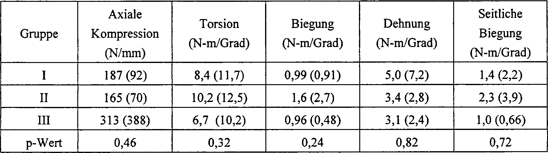
Werte in runden Klammern verkörpern die Standardabweichungenvalues embody in parenthesis the standard deviations
TABELLE
III
Ergebnisse der mechanischen Prüfung 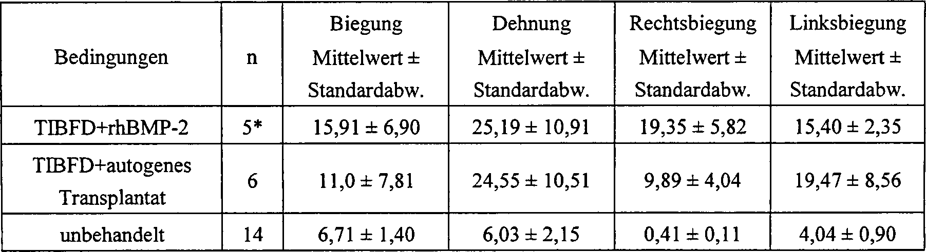

TABELLE
V
Ergebnisse Zwischenkörperhöhenindex:
von 0 bis 6 Monate 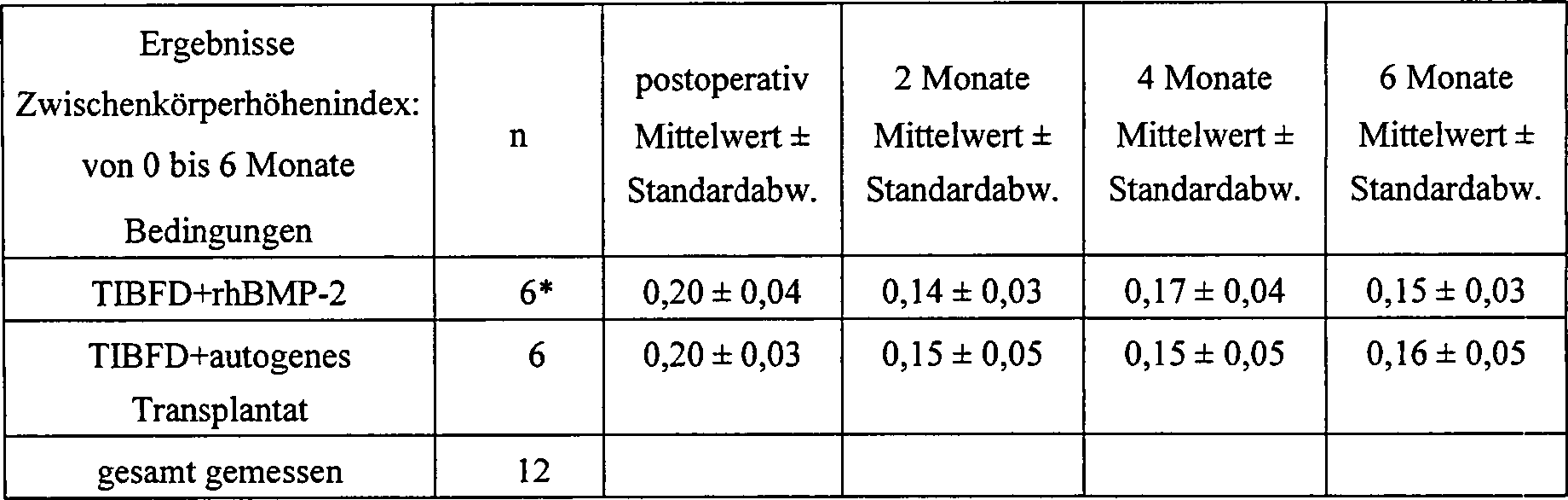
BEISPIEL 5EXAMPLE 5
Logische Grundlage der PrüfungLogical basis of exam
Die Prüfung wurde bei Endkappen durchgeführt, um den Widerstand der Endkappe gegen ein Austoßen durch einen rhBMP-2-getränkten Kollagenschwamm zu messen, und um den Widerstand mit einer bekannten Polyethylenendkappe zu vergleichen.The exam was done on end caps, the resistance of the end cap against expulsion by a rhBMP-2 soaked collagen sponge to measure, and the resistance with a known polyethylene end cap to compare.
VERSUCH AATTEMPT A
Ausstoßversuch bei einer mit Preßpassung angeordneten EndkappeEjection attempt at one with press fit arranged end cap
Dieser Versuch wurde durchgeführt, um die statische Kraft zu ermitteln, die für das Entfernen einer mit Preßpassung angeordneten Polyethylenendkappe aus einem BAKTM-Teil (Spine Tech, Minneapolis, MN) erforderlich ist. Die Endkappe wurde am BackTM-Teil eingeschnappt, und eine axiale Belastung wurde durch den Hohlraum des BackTM-Teils auf die Endkappe angewandt. Die Ausstoßbelastung für fünf (5) Proben bewegte sich im Bereich von 12 bis 37 lbs Kraft.This experiment was conducted to determine the static force required to remove a press fit polyethylene end cap from a BAK ™ part (Spine Tech, Minneapolis, MN). The end cap was snapped on the Back TM part and axial loading was applied to the end cap through the cavity of the Back TM part. The discharge load for five (5) samples ranged from 12 to 37 lbs of force.
VERSUCH BATTEMPT B
Versuchsanordnung und VerfahrenExperimental arrangement and method
Fünf (5) Proben
einer 12 mm Titan-Endkappe (894-120, Sofamor Danek, USA) (894-XXX,
Sofamor Danek, USA, Memphis, Tennessee) wurden jeweils in einem
12 mm Titan-Implantat NOVUSTMLT (Sofamor
Danek, USA) angeordnet, wie in
ERGEBNISSERESULTS
Alle Endkappen werden mittels einer elastischen Durchbiegung der zwei Ankergabelzinken herausgezogen. Die mittlere Herausziehbelastung betrug 187 N (41,99 lb Kraft). Die Tabelle I zeigt die unverarbeiteten Daten für die Herausziehversuche.All End caps are by means of an elastic deflection of the two Anchor fork tines withdrawn. The mean pull-out load was 187 N (41.99 lb force). Table I shows the raw data for the Pull-out tests.
VERSUCH CATTEMPT C
Die Verfahren des Versuchs B wurden bei neun (9) Proben wiederholt, außer daß die Belastung mit einer Geschwindigkeit von 12,5 mm/min. angewandt wurde. Die mittlere Herausziehbelastung betrug 30,57 mittlere Kraft in lbs.The Experiment B procedures were repeated on nine (9) samples, except that the Load at a speed of 12.5 mm / min. was applied. The mean extraction load was 30.57 mean force in lbs.
Der Wert von 30,57 läßt sich gut mit dem Wert von 41,99 beim Versuch B vergleichen. Der Probenumfang für diese Prüfung betrug 9, während der Probenumfang beim Versuch B 5 betrug.The value of 30.57 compares well with the value of 41.99 in experiment B. The sample um for this test was 9, while the sample size in experiment B was 5.
DISKUSSION UND SCHLUSSFOLGERUNGENDISCUSSION AND CONCLUSIONS
Die Prüfungsergebnisse zeigen, daß die Endkappe dieser Erfindung gegen ein Ausstoßen in vivo aus zwei Gründen beständig ist. Erstens ist gut bekannt, daß die Zwischenwirbelbandscheibe unter einer komplizierten kombinierten Belastung steht. Keine der Belastungen, die auf den Bandscheibenzwischenraum wirkt, würde jedoch direkt auf die Endkappe des Implantates wirken, um ein Ausstoßen der Endkappe hervorzurufen. Zweitens ist es unwahrscheinlich, daß der rhBMP-2-getränkte Kollagenschwamm 177 N (41,99 lb Kraft) an Kraft ausüben könnte, um die Endkappe auszustoßen.The exam results show that the End cap of this invention is resistant to expulsion in vivo for two reasons. First, it is well known that the Intervertebral disc under a complicated combined Load is. None of the burdens on the intervertebral space works, would However, act directly on the end cap of the implant to eject the Cause the end cap. Second, it is unlikely that the rhBMP-2 soaked collagen sponge 177 N (41.99 lb force) of force to eject the end cap.
Die Ankergabelzinkenendkappen dieser Erfindung wurden leicht von Hand in die Teile eingesetzt. In einem Fall wurde die Endkappe mittels der servohydraulischen Prüfmaschine eingesetzt. Die Einsetzlast wurde gemessen und als 3,2 lb Kraft ermittelt. Das liefert eine zusätzliche Unterstützung für den vollen Endkappeneingriff. Die durchschnittliche Ausstoßkraft beträgt das 13-fache der Einsetzlast.The Anchor fork end caps of this invention were easily hand-held used in the parts. In one case, the end cap was using the servohydraulic testing machine used. The loading load was measured and as 3.2 lb force determined. That provides an extra support for the full end cap engagement. The average ejection force is 13 times the insertion load.
Die Ankergabelzinkenendkappen dieser Erfindung lassen sich sehr günstig mit einer bekannten durch Preßpassung angeordneten Polyethylenendkappenkonstruktion vergleichen. Die mit Preßpassung angeordnete Kappe zeigte durchschnittlich 25 lbs Kraft mit einem Bereich von 12 bis 37 lbs. Die Ankergabelzinkenkappe dieser Erfindung überschritt jene Werte mit einem Mittelwert von 30,57 lbs und einem Bereich von 12,5 bis 46,62 lbs Kraft über neun (9) Proben.The Ankerbabelzinkenendkappen this invention can be very cheap with a known by interference fit arranged polyethylene end cap construction compare. With press fit arranged cap showed on average 25 lbs of force with one Range from 12 to 37 lbs. The anchor fork zinc cap of this invention passed those values with a mean of 30.57 pounds and a range from 12.5 to 46.62 pounds of force over nine (9) samples.
Claims (14)
Applications Claiming Priority (8)
| Application Number | Priority Date | Filing Date | Title |
|---|---|---|---|
| US08/411,017 US5782919A (en) | 1995-03-27 | 1995-03-27 | Interbody fusion device and method for restoration of normal spinal anatomy |
| US08/413,353 US5669909A (en) | 1995-03-27 | 1995-03-30 | Interbody fusion device and method for restoration of normal spinal anatomy |
| US603674 | 1996-02-19 | ||
| US08/603,674 US5984967A (en) | 1995-03-27 | 1996-02-19 | Osteogenic fusion devices |
| US79911497A | 1997-02-11 | 1997-02-11 | |
| US799114 | 1997-02-11 | ||
| PCT/US1997/002672 WO1997031517A2 (en) | 1995-03-27 | 1997-02-19 | Spinal fusion implants and tools for insertion and revision |
| US80354197A | 1997-02-20 | 1997-02-20 |
Publications (2)
| Publication Number | Publication Date |
|---|---|
| DE69732226D1 DE69732226D1 (en) | 2005-02-17 |
| DE69732226T2 true DE69732226T2 (en) | 2005-12-22 |
Family
ID=27767954
Family Applications (2)
| Application Number | Title | Priority Date | Filing Date |
|---|---|---|---|
| DE69732226T Expired - Fee Related DE69732226T2 (en) | 1995-03-27 | 1997-02-19 | SPIN-FUSION IMPLANT AND INTRODUCTION AND INSPECTION TOOLS |
| DE69737756T Expired - Lifetime DE69737756T2 (en) | 1995-03-27 | 1997-02-19 | Spinal fusion implant |
Family Applications After (1)
| Application Number | Title | Priority Date | Filing Date |
|---|---|---|---|
| DE69737756T Expired - Lifetime DE69737756T2 (en) | 1995-03-27 | 1997-02-19 | Spinal fusion implant |
Country Status (8)
| Country | Link |
|---|---|
| US (3) | US6613091B1 (en) |
| EP (2) | EP1504732B1 (en) |
| JP (2) | JP3808103B2 (en) |
| AT (2) | ATE362740T1 (en) |
| DE (2) | DE69732226T2 (en) |
| ES (2) | ES2236792T3 (en) |
| PT (1) | PT1504732E (en) |
| WO (1) | WO1997031517A2 (en) |
Families Citing this family (299)
| Publication number | Priority date | Publication date | Assignee | Title |
|---|---|---|---|---|
| DE20004692U1 (en) * | 2000-03-14 | 2001-07-26 | Sofamor Danek GmbH, 94469 Deggendorf | Vertebral implant for screwing into an intervertebral space |
| US5609635A (en) * | 1988-06-28 | 1997-03-11 | Michelson; Gary K. | Lordotic interbody spinal fusion implants |
| DE69732226T2 (en) * | 1995-03-27 | 2005-12-22 | SDGI Holdings, Inc., Wilmington | SPIN-FUSION IMPLANT AND INTRODUCTION AND INSPECTION TOOLS |
| US6206922B1 (en) | 1995-03-27 | 2001-03-27 | Sdgi Holdings, Inc. | Methods and instruments for interbody fusion |
| DE19750382A1 (en) * | 1997-11-13 | 1999-05-20 | Augustin Prof Dr Med Betz | Operative correction equipment for displaced vertebrae used in minimally invasive surgery |
| DE19753685C1 (en) * | 1997-12-03 | 1999-09-16 | Biedermann Motech Gmbh | Intravertebral surgical implant |
| US20010001129A1 (en) * | 1997-12-10 | 2001-05-10 | Mckay William F. | Osteogenic fusion device |
| FR2772594B1 (en) * | 1997-12-19 | 2000-05-05 | Henry Graf | REAR PARTIAL DISCAL PROSTHESIS |
| AU775275B2 (en) * | 1997-12-19 | 2004-07-29 | Warsaw Orthopedic, Inc. | Partial disc prosthesis |
| WO1999060837A2 (en) * | 1998-05-27 | 1999-12-02 | Nuvasive, Inc. | Bone blocks and methods for inserting |
| US6086593A (en) | 1998-06-30 | 2000-07-11 | Bonutti; Peter M. | Method and apparatus for use in operating on a bone |
| US6099531A (en) * | 1998-08-20 | 2000-08-08 | Bonutti; Peter M. | Changing relationship between bones |
| US6174311B1 (en) * | 1998-10-28 | 2001-01-16 | Sdgi Holdings, Inc. | Interbody fusion grafts and instrumentation |
| US6193757B1 (en) | 1998-10-29 | 2001-02-27 | Sdgi Holdings, Inc. | Expandable intervertebral spacers |
| ATE304335T1 (en) | 1999-01-11 | 2005-09-15 | Sdgi Holdings Inc | INTERVERBEL SPACER WITH ACCESSIBLE INTERIOR THROUGH SIDE WALLS |
| AU2008202022B2 (en) * | 1999-05-05 | 2011-02-24 | Warsaw Orthopedic, Inc. | Interbody spinal fusion implants |
| CA2363562C (en) * | 1999-05-05 | 2010-08-03 | Gary Karlin Michelson | Nested interbody spinal fusion implants |
| FR2794362B1 (en) | 1999-06-02 | 2001-09-21 | Henry Graf | INTERVERTEBRAL IMPLANT AND POSITIONING ASSEMBLY OF SUCH AN IMPLANT |
| ATE388677T1 (en) | 1999-07-02 | 2008-03-15 | Spine Solutions Inc | INTERVERBARY IMPLANT |
| FR2897259B1 (en) | 2006-02-15 | 2008-05-09 | Ldr Medical Soc Par Actions Si | INTERSOMATIC TRANSFORAMINAL CAGE WITH INTERBREBAL FUSION GRAFT AND CAGE IMPLANTATION INSTRUMENT |
| NZ517741A (en) | 1999-09-14 | 2006-05-26 | Spine Solutions Inc | Insertion instrument for an intervertebral implant |
| US6878167B2 (en) * | 2002-04-24 | 2005-04-12 | Bret A. Ferree | Methods and apparatus for placing intradiscal devices |
| WO2001028461A2 (en) * | 1999-10-20 | 2001-04-26 | Sdgi Holdings, Inc. | Impacted orthopedic bone support implant |
| ATE336952T1 (en) | 1999-12-01 | 2006-09-15 | Henry Graf | DEVICE FOR INTERVERBEL STABILIZATION |
| US7744588B2 (en) * | 2002-05-21 | 2010-06-29 | Kensey Nash Corporation | Tool for facilitating the connecting of a catheter or other tubular member onto a guide-wire without access to the ends of the guide wire |
| FR2808995B1 (en) | 2000-05-18 | 2003-02-21 | Aesculap Sa | INTERSOMATIC CAGE WITH UNIFIED GRAFT |
| US20020169507A1 (en) * | 2000-12-14 | 2002-11-14 | David Malone | Interbody spine fusion cage |
| US6849093B2 (en) * | 2001-03-09 | 2005-02-01 | Gary K. Michelson | Expansion constraining member adapted for use with an expandable interbody spinal fusion implant and method for use thereof |
| EP1389978B1 (en) * | 2001-05-01 | 2009-01-07 | Amedica Corporation | Radiolucent bone graft |
| FR2824261B1 (en) | 2001-05-04 | 2004-05-28 | Ldr Medical | INTERVERTEBRAL DISC PROSTHESIS AND IMPLEMENTATION METHOD AND TOOLS |
| EP1408874B1 (en) | 2001-06-14 | 2012-08-08 | Amedica Corporation | Metal-ceramic composite articulation |
| FR2827156B1 (en) | 2001-07-13 | 2003-11-14 | Ldr Medical | VERTEBRAL CAGE DEVICE WITH MODULAR FASTENING |
| US7267687B2 (en) | 2001-10-02 | 2007-09-11 | Rex Medical, L.P | Spinal implant and method of use |
| DE20205016U1 (en) * | 2002-03-30 | 2003-08-14 | Mathys Medizinaltechnik Ag, Bettlach | Surgical implant |
| US7232463B2 (en) * | 2002-10-23 | 2007-06-19 | U.S. Spinal Technologies, Llc | Intervertebral cage designs |
| FR2846550B1 (en) | 2002-11-05 | 2006-01-13 | Ldr Medical | INTERVERTEBRAL DISC PROSTHESIS |
| US7204852B2 (en) | 2002-12-13 | 2007-04-17 | Spine Solutions, Inc. | Intervertebral implant, insertion tool and method of inserting same |
| AU2003297195A1 (en) * | 2002-12-17 | 2004-07-22 | Amedica Corporation | Total disc implant |
| FR2848414B1 (en) * | 2002-12-17 | 2005-02-25 | Vitatech | INTERSOMATIC IMPLANT FOR VERTEBRATES |
| WO2004084742A1 (en) | 2003-03-24 | 2004-10-07 | Theken Surgical Llc | Spinal implant adjustment device |
| US7819903B2 (en) * | 2003-03-31 | 2010-10-26 | Depuy Spine, Inc. | Spinal fixation plate |
| US7112222B2 (en) * | 2003-03-31 | 2006-09-26 | Depuy Spine, Inc. | Anterior lumbar interbody fusion cage with locking plate |
| US7491204B2 (en) | 2003-04-28 | 2009-02-17 | Spine Solutions, Inc. | Instruments and method for preparing an intervertebral space for receiving an artificial disc implant |
| US8039090B2 (en) * | 2003-05-26 | 2011-10-18 | Hoya Corporation | Porous composite containing calcium phosphate and process for producing the same |
| US8998919B2 (en) | 2003-06-25 | 2015-04-07 | DePuy Synthes Products, LLC | Assembly tool for modular implants, kit and associated method |
| US7582092B2 (en) | 2003-06-25 | 2009-09-01 | Depuy Products, Inc. | Assembly tool for modular implants and associated method |
| US7803162B2 (en) | 2003-07-21 | 2010-09-28 | Spine Solutions, Inc. | Instruments and method for inserting an intervertebral implant |
| US7235105B2 (en) * | 2003-09-18 | 2007-06-26 | Jackson Roger P | Threaded center line cage with winged end gap |
| US20050065605A1 (en) * | 2003-09-18 | 2005-03-24 | Jackson Roger P. | Threaded center line cage with funnel shaped profile |
| US7837732B2 (en) | 2003-11-20 | 2010-11-23 | Warsaw Orthopedic, Inc. | Intervertebral body fusion cage with keels and implantation methods |
| US8389588B2 (en) | 2003-12-04 | 2013-03-05 | Kensey Nash Corporation | Bi-phasic compressed porous reinforcement materials suitable for implant |
| US7723395B2 (en) * | 2004-04-29 | 2010-05-25 | Kensey Nash Corporation | Compressed porous materials suitable for implant |
| US8133500B2 (en) * | 2003-12-04 | 2012-03-13 | Kensey Nash Bvf Technology, Llc | Compressed high density fibrous polymers suitable for implant |
| US7979150B2 (en) * | 2003-12-05 | 2011-07-12 | The Regents Of The University Of Michigan | Biodegradable/bioresorbable tissue augmentation/reconstruction device |
| JP2007518528A (en) * | 2004-01-22 | 2007-07-12 | イソフラックス・インコーポレイテッド | Radiopaque coatings for biomedical devices |
| US8002822B2 (en) | 2004-01-22 | 2011-08-23 | Isoflux, Inc. | Radiopaque coating for biomedical devices |
| JP4996927B2 (en) | 2004-02-04 | 2012-08-08 | エル・デ・エール・メデイカル | Intervertebral disc prosthesis |
| FR2865629B1 (en) | 2004-02-04 | 2007-01-26 | Ldr Medical | INTERVERTEBRAL DISC PROSTHESIS |
| AU2005212352B2 (en) * | 2004-02-09 | 2010-11-18 | Depuy Spine, Inc. | Systems and methods for spinal surgery |
| CN100591305C (en) * | 2004-02-13 | 2010-02-24 | 小弗朗茨·科波夫 | Intervertebral implant and surgical method for lumbar spinal fusion |
| US7485145B2 (en) * | 2004-02-23 | 2009-02-03 | Alphatec Spine, Incorporated | Artificial intervertebral disc assembly |
| WO2005102226A1 (en) * | 2004-04-26 | 2005-11-03 | Synthes Gmbh | Intervertebral prosthesis or disk prosthesis |
| FR2869528B1 (en) | 2004-04-28 | 2007-02-02 | Ldr Medical | INTERVERTEBRAL DISC PROSTHESIS |
| US7544208B1 (en) | 2004-05-03 | 2009-06-09 | Theken Spine, Llc | Adjustable corpectomy apparatus |
| CA2572072C (en) * | 2004-06-28 | 2013-06-11 | Isoflux, Inc. | Porous coatings for biomedical implants |
| CA2573329A1 (en) * | 2004-07-13 | 2006-02-16 | Isoflux, Inc. | Porous coatings on electrodes for biomedical implants |
| US7594919B2 (en) * | 2004-07-23 | 2009-09-29 | Warsaw Orthopedic, Inc. | Artificial disc inserter |
| US9662158B2 (en) | 2004-08-09 | 2017-05-30 | Si-Bone Inc. | Systems and methods for the fixation or fusion of bone at or near a sacroiliac joint |
| US8986348B2 (en) | 2004-08-09 | 2015-03-24 | Si-Bone Inc. | Systems and methods for the fusion of the sacral-iliac joint |
| US20180228621A1 (en) | 2004-08-09 | 2018-08-16 | Mark A. Reiley | Apparatus, systems, and methods for the fixation or fusion of bone |
| US20070156241A1 (en) | 2004-08-09 | 2007-07-05 | Reiley Mark A | Systems and methods for the fixation or fusion of bone |
| US9949843B2 (en) | 2004-08-09 | 2018-04-24 | Si-Bone Inc. | Apparatus, systems, and methods for the fixation or fusion of bone |
| US8414648B2 (en) | 2004-08-09 | 2013-04-09 | Si-Bone Inc. | Apparatus, systems, and methods for achieving trans-iliac lumbar fusion |
| US20060036251A1 (en) | 2004-08-09 | 2006-02-16 | Reiley Mark A | Systems and methods for the fixation or fusion of bone |
| US8425570B2 (en) | 2004-08-09 | 2013-04-23 | Si-Bone Inc. | Apparatus, systems, and methods for achieving anterior lumbar interbody fusion |
| US7465306B2 (en) * | 2004-08-13 | 2008-12-16 | Warsaw Orthopedic, Inc. | System and method for positioning a connecting member adjacent the spinal column in minimally invasive procedures |
| US7799081B2 (en) | 2004-09-14 | 2010-09-21 | Aeolin, Llc | System and method for spinal fusion |
| US7666189B2 (en) * | 2004-09-29 | 2010-02-23 | Synthes Usa, Llc | Less invasive surgical system and methods |
| US7963995B2 (en) * | 2004-10-05 | 2011-06-21 | Aesculap, Inc. | Minimally invasive spine implant for restoration of motion |
| USD524942S1 (en) | 2005-05-23 | 2006-07-11 | Felix Brent A | Surgical implant |
| US7794500B2 (en) * | 2004-10-27 | 2010-09-14 | Felix Brent A | Surgical implant |
| WO2006050493A2 (en) | 2004-11-03 | 2006-05-11 | The Regents Of The University Of Michigan | Biodegradable implant for intertransverse process fusion |
| US20060095136A1 (en) * | 2004-11-03 | 2006-05-04 | Mcluen Design, Inc. | Bone fusion device |
| US8597360B2 (en) | 2004-11-03 | 2013-12-03 | Neuropro Technologies, Inc. | Bone fusion device |
| US20060111786A1 (en) * | 2004-11-22 | 2006-05-25 | Orthopedic Development Corporation | Metallic prosthetic implant for use in minimally invasive acromio-clavicular shoulder joint hemi-arthroplasty |
| US20060111780A1 (en) | 2004-11-22 | 2006-05-25 | Orthopedic Development Corporation | Minimally invasive facet joint hemi-arthroplasty |
| US8021392B2 (en) | 2004-11-22 | 2011-09-20 | Minsurg International, Inc. | Methods and surgical kits for minimally-invasive facet joint fusion |
| US20060111779A1 (en) | 2004-11-22 | 2006-05-25 | Orthopedic Development Corporation, A Florida Corporation | Minimally invasive facet joint fusion |
| US8172855B2 (en) | 2004-11-24 | 2012-05-08 | Abdou M S | Devices and methods for inter-vertebral orthopedic device placement |
| FR2879436B1 (en) | 2004-12-22 | 2007-03-09 | Ldr Medical | INTERVERTEBRAL DISC PROSTHESIS |
| US7690381B2 (en) * | 2005-02-10 | 2010-04-06 | Depuy Spine, Inc. | Intervertebral prosthetic disc and method for installing using a guidewire |
| US8911498B2 (en) * | 2005-02-10 | 2014-12-16 | DePuy Synthes Products, LLC | Intervertebral prosthetic disc |
| US8673006B2 (en) * | 2005-03-24 | 2014-03-18 | Igip, Llc | Spinal implant |
| US9456907B1 (en) | 2005-03-24 | 2016-10-04 | Igip, Llc | Extendable spinal implant |
| US8986383B2 (en) * | 2005-03-24 | 2015-03-24 | Igip, Llc | End cap and connector for a spinal implant |
| USD530423S1 (en) * | 2005-03-29 | 2006-10-17 | Nuvasive, Inc. | Intervertebral implant |
| US20060229723A1 (en) * | 2005-04-08 | 2006-10-12 | Sdgi Holdings, Inc. | Intervertebral fusion device and method |
| US20060241566A1 (en) * | 2005-04-11 | 2006-10-26 | Orthox, Llc | Nucleus Extraction from Spine Intervertebral Disc |
| US20060241766A1 (en) * | 2005-04-20 | 2006-10-26 | Sdgi Holdings, Inc. | Method and apparatus for preventing articulation in an artificial joint |
| US7491208B2 (en) | 2005-04-28 | 2009-02-17 | Warsaw Orthopedic, Inc. | Instrument and method for guiding surgical implants and instruments during surgery |
| BRPI0610801A2 (en) * | 2005-05-18 | 2017-01-31 | Surmodics Inc | insertion instrument for rotatably inserting a medical device that may be inserted into a portion of the eye, and kit for rotatably inserting a medical device that may be inserted including a nonlinear shape in a portion of the eye |
| GB0514891D0 (en) * | 2005-07-20 | 2005-08-24 | Pearsalls Ltd | Improvements in and relating to implants |
| US8092548B2 (en) | 2005-06-22 | 2012-01-10 | Warsaw Orthopedic, Inc. | Osteograft treatment to promote osteoinduction and osteograft incorporation |
| FR2887762B1 (en) | 2005-06-29 | 2007-10-12 | Ldr Medical Soc Par Actions Si | INTERVERTEBRAL DISC PROSTHESIS INSERTION INSTRUMENTATION BETWEEN VERTEBRATES |
| US8623088B1 (en) | 2005-07-15 | 2014-01-07 | Nuvasive, Inc. | Spinal fusion implant and related methods |
| FR2891135B1 (en) | 2005-09-23 | 2008-09-12 | Ldr Medical Sarl | INTERVERTEBRAL DISC PROSTHESIS |
| US8152814B2 (en) * | 2005-09-30 | 2012-04-10 | Depuy Products, Inc. | Separator tool for a modular prosthesis |
| US20070077267A1 (en) * | 2005-10-03 | 2007-04-05 | Sdgi Holdings, Inc. | Bioactive composite implants |
| USD524443S1 (en) * | 2005-11-04 | 2006-07-04 | Quantum Orthopedics, Inc. | Interbody fusion device |
| USD533277S1 (en) | 2005-11-04 | 2006-12-05 | Quantum Orthopedics, Inc. | Interbody fusion device |
| FR2893838B1 (en) | 2005-11-30 | 2008-08-08 | Ldr Medical Soc Par Actions Si | PROSTHESIS OF INTERVERTEBRAL DISC AND INSTRUMENTATION OF INSERTION OF THE PROSTHESIS BETWEEN VERTEBRATES |
| FR2894130B1 (en) * | 2005-12-05 | 2012-07-13 | Spineart Sa | CAGES OF CONTENTION AND INTERSOMATIC FUSION OF VERTEBRATES |
| US20070173941A1 (en) * | 2006-01-25 | 2007-07-26 | Sdgi Holdings, Inc. | Intervertebral prosthetic disc and method of installing same |
| EP1826293A1 (en) * | 2006-02-09 | 2007-08-29 | Isoflux, Inc. | Formation of nanoscale surfaces for the attachment of biological materials |
| US20080299337A1 (en) * | 2006-02-09 | 2008-12-04 | Isoflux, Inc. | Method for the formation of surfaces on the inside of medical devices |
| US20070213822A1 (en) | 2006-02-14 | 2007-09-13 | Sdgi Holdings, Inc. | Treatment of the vertebral column |
| EP2004079B1 (en) | 2006-04-11 | 2013-07-10 | Synthes GmbH | Minimally invasive fixation system |
| US20070255414A1 (en) * | 2006-05-01 | 2007-11-01 | Sdgi Holdings, Inc. | Intervertebral implants with one or more covers and methods of use |
| US7658766B2 (en) * | 2006-05-01 | 2010-02-09 | Warsaw Orthopedic, Inc. | Intervertebral implants with covered inner chamber and methods of use |
| US7833270B2 (en) * | 2006-05-05 | 2010-11-16 | Warsaw Orthopedic, Inc | Implant depots to deliver growth factors to treat osteoporotic bone |
| US20070265633A1 (en) * | 2006-05-11 | 2007-11-15 | Moon Jon K | Implement and method to extract nucleus from spine intervertebral disc |
| US8303601B2 (en) | 2006-06-07 | 2012-11-06 | Stryker Spine | Collet-activated distraction wedge inserter |
| USD741488S1 (en) | 2006-07-17 | 2015-10-20 | Nuvasive, Inc. | Spinal fusion implant |
| WO2008014258A2 (en) | 2006-07-24 | 2008-01-31 | Spine Solutions, Inc. | Intervertebral implant with keel |
| ES2687619T3 (en) | 2006-07-31 | 2018-10-26 | Centinel Spine Schweiz Gmbh | Milling guide and keel trimming preparation system |
| US9526525B2 (en) | 2006-08-22 | 2016-12-27 | Neuropro Technologies, Inc. | Percutaneous system for dynamic spinal stabilization |
| US20080161927A1 (en) * | 2006-10-18 | 2008-07-03 | Warsaw Orthopedic, Inc. | Intervertebral Implant with Porous Portions |
| US12171904B2 (en) | 2006-10-30 | 2024-12-24 | Trs Holdings Llc | Mineral coated scaffolds |
| US8275594B2 (en) * | 2006-10-30 | 2012-09-25 | The Regents Of The University Of Michigan | Engineered scaffolds for intervertebral disc repair and regeneration and for articulating joint repair and regeneration |
| US9439948B2 (en) * | 2006-10-30 | 2016-09-13 | The Regents Of The University Of Michigan | Degradable cage coated with mineral layers for spinal interbody fusion |
| CA2668655A1 (en) | 2006-11-16 | 2008-05-29 | Rex Medical, L.P. | Spinal implant and method of use |
| US7803159B2 (en) * | 2006-11-29 | 2010-09-28 | Mi4Spine, Llc | Disc space preparation device for spinal surgery |
| US20080154374A1 (en) * | 2006-12-20 | 2008-06-26 | Robert David Labrom | Joint implant and a surgical method associated therewith |
| US7824427B2 (en) * | 2007-01-16 | 2010-11-02 | Perez-Cruet Miquelangelo J | Minimally invasive interbody device |
| US7942104B2 (en) | 2007-01-22 | 2011-05-17 | Nuvasive, Inc. | 3-dimensional embroidery structures via tension shaping |
| US7946236B2 (en) | 2007-01-31 | 2011-05-24 | Nuvasive, Inc. | Using zigzags to create three-dimensional embroidered structures |
| US20100320639A1 (en) * | 2007-02-08 | 2010-12-23 | Christopher Reah | Medical Implants with Pre-Settled Cores and Related Methods |
| US8465546B2 (en) | 2007-02-16 | 2013-06-18 | Ldr Medical | Intervertebral disc prosthesis insertion assemblies |
| US20080281425A1 (en) * | 2007-02-21 | 2008-11-13 | John Thalgott | Orthopaedic Implants and Prostheses |
| US20080249569A1 (en) * | 2007-04-03 | 2008-10-09 | Warsaw Orthopedic, Inc. | Implant Face Plates |
| US8268000B2 (en) * | 2007-04-03 | 2012-09-18 | Warsaw Orthopedic, Inc. | Composite interbody spacer |
| US8425607B2 (en) * | 2007-04-03 | 2013-04-23 | Warsaw Orthopedic, Inc. | Anchor member locking features |
| FR2916956B1 (en) | 2007-06-08 | 2012-12-14 | Ldr Medical | INTERSOMATIC CAGE, INTERVERTEBRAL PROSTHESIS, ANCHORING DEVICE AND IMPLANTATION INSTRUMENTATION |
| US8282681B2 (en) * | 2007-08-13 | 2012-10-09 | Nuvasive, Inc. | Bioresorbable spinal implant and related methods |
| US8556912B2 (en) * | 2007-10-30 | 2013-10-15 | DePuy Synthes Products, LLC | Taper disengagement tool |
| US20090112219A1 (en) * | 2007-10-31 | 2009-04-30 | Daniels David W | Taper sleeve extractor |
| US8518050B2 (en) | 2007-10-31 | 2013-08-27 | DePuy Synthes Products, LLC | Modular taper assembly device |
| WO2009081503A1 (en) | 2007-12-21 | 2009-07-02 | Yukihide Iwamoto | Device for cell transplantation |
| US8088163B1 (en) | 2008-02-06 | 2012-01-03 | Kleiner Jeffrey B | Tools and methods for spinal fusion |
| JP5266069B2 (en) * | 2008-02-07 | 2013-08-21 | 昭和医科工業株式会社 | cage |
| FR2927250B1 (en) * | 2008-02-11 | 2010-03-12 | Neuro France Implants Nfi | INTERSOMATIC CAGE |
| US8377135B1 (en) | 2008-03-31 | 2013-02-19 | Nuvasive, Inc. | Textile-based surgical implant and related methods |
| EP3020410A1 (en) | 2008-04-18 | 2016-05-18 | Collplant Ltd. | Methods of generating and using procollagen |
| US8915962B1 (en) * | 2008-04-24 | 2014-12-23 | Loubert S. Suddaby | Facet joint fixation device |
| WO2016044824A1 (en) * | 2008-05-07 | 2016-03-24 | George Frey | Configurable intervertebral implant |
| US20210378834A1 (en) | 2008-05-22 | 2021-12-09 | Spinal Surgical Strategies, Inc., A Nevada Corporation D/B/A Kleiner Device Labs | Spinal fusion cage system with inserter |
| US10842645B2 (en) | 2008-08-13 | 2020-11-24 | Smed-Ta/Td, Llc | Orthopaedic implant with porous structural member |
| US9358056B2 (en) * | 2008-08-13 | 2016-06-07 | Smed-Ta/Td, Llc | Orthopaedic implant |
| US20100042213A1 (en) | 2008-08-13 | 2010-02-18 | Nebosky Paul S | Drug delivery implants |
| US20100042218A1 (en) * | 2008-08-13 | 2010-02-18 | Nebosky Paul S | Orthopaedic implant with porous structural member |
| US9700431B2 (en) | 2008-08-13 | 2017-07-11 | Smed-Ta/Td, Llc | Orthopaedic implant with porous structural member |
| WO2010019788A1 (en) | 2008-08-13 | 2010-02-18 | Smed-Ta/Td. Llc | Drug delivery implants |
| US9616205B2 (en) | 2008-08-13 | 2017-04-11 | Smed-Ta/Td, Llc | Drug delivery implants |
| US8366748B2 (en) | 2008-12-05 | 2013-02-05 | Kleiner Jeffrey | Apparatus and method of spinal implant and fusion |
| US10045860B2 (en) | 2008-12-19 | 2018-08-14 | Amicus Design Group, Llc | Interbody vertebral prosthetic device with self-deploying screws |
| CA2747660A1 (en) | 2008-12-22 | 2010-07-01 | Synthes Usa, Llc | Orthopedic implant with flexible keel |
| US9247943B1 (en) | 2009-02-06 | 2016-02-02 | Kleiner Intellectual Property, Llc | Devices and methods for preparing an intervertebral workspace |
| US20100222750A1 (en) * | 2009-02-27 | 2010-09-02 | Vanderbilt University | Replenishable drug delivery implant for bone and cartilage |
| US9439685B2 (en) | 2009-05-12 | 2016-09-13 | Bullard Spine, Llc | Multi-layer osteoinductive, osteogenic, and osteoconductive carrier |
| JP5658237B2 (en) | 2009-05-20 | 2015-01-21 | ジンテス ゲゼルシャフト ミット ベシュレンクテル ハフツング | Patient-mounted retractor |
| US9399086B2 (en) | 2009-07-24 | 2016-07-26 | Warsaw Orthopedic, Inc | Implantable medical devices |
| US20110028981A1 (en) * | 2009-07-29 | 2011-02-03 | Warsaw Orthopedic, Inc. | Bone graft measuring apparatus and method of use |
| EP2477579B1 (en) | 2009-09-17 | 2015-12-23 | LDR Holding Corporation | Intervertebral implant having extendable bone fixation members |
| US8906028B2 (en) | 2009-09-18 | 2014-12-09 | Spinal Surgical Strategies, Llc | Bone graft delivery device and method of using the same |
| US10245159B1 (en) | 2009-09-18 | 2019-04-02 | Spinal Surgical Strategies, Llc | Bone graft delivery system and method for using same |
| US20170238984A1 (en) | 2009-09-18 | 2017-08-24 | Spinal Surgical Strategies, Llc | Bone graft delivery device with positioning handle |
| US8685031B2 (en) | 2009-09-18 | 2014-04-01 | Spinal Surgical Strategies, Llc | Bone graft delivery system |
| US9173694B2 (en) | 2009-09-18 | 2015-11-03 | Spinal Surgical Strategies, Llc | Fusion cage with combined biological delivery system |
| US9629729B2 (en) | 2009-09-18 | 2017-04-25 | Spinal Surgical Strategies, Llc | Biological delivery system with adaptable fusion cage interface |
| US9186193B2 (en) | 2009-09-18 | 2015-11-17 | Spinal Surgical Strategies, Llc | Fusion cage with combined biological delivery system |
| USD723682S1 (en) | 2013-05-03 | 2015-03-03 | Spinal Surgical Strategies, Llc | Bone graft delivery tool |
| USD750249S1 (en) | 2014-10-20 | 2016-02-23 | Spinal Surgical Strategies, Llc | Expandable fusion cage |
| US9060877B2 (en) | 2009-09-18 | 2015-06-23 | Spinal Surgical Strategies, Llc | Fusion cage with combined biological delivery system |
| US10973656B2 (en) | 2009-09-18 | 2021-04-13 | Spinal Surgical Strategies, Inc. | Bone graft delivery system and method for using same |
| USD731063S1 (en) | 2009-10-13 | 2015-06-02 | Nuvasive, Inc. | Spinal fusion implant |
| US8764806B2 (en) | 2009-12-07 | 2014-07-01 | Samy Abdou | Devices and methods for minimally invasive spinal stabilization and instrumentation |
| US9833331B2 (en) | 2009-12-31 | 2017-12-05 | Ldr Medical | Anchoring device and system for an intervertebral implant, intervertebral implant and implantation instrument |
| US9421109B2 (en) | 2010-01-13 | 2016-08-23 | Jcbd, Llc | Systems and methods of fusing a sacroiliac joint |
| WO2012174485A1 (en) | 2011-06-17 | 2012-12-20 | Jcbd, Llc | Sacroiliac joint implant system |
| US9554909B2 (en) | 2012-07-20 | 2017-01-31 | Jcbd, Llc | Orthopedic anchoring system and methods |
| US9381045B2 (en) | 2010-01-13 | 2016-07-05 | Jcbd, Llc | Sacroiliac joint implant and sacroiliac joint instrument for fusing a sacroiliac joint |
| US9333090B2 (en) | 2010-01-13 | 2016-05-10 | Jcbd, Llc | Systems for and methods of fusing a sacroiliac joint |
| KR101754138B1 (en) | 2010-01-13 | 2017-07-05 | 제이씨비디, 엘엘씨 | Sacroiliac joint fixation fusion system |
| AU2011227293A1 (en) | 2010-03-16 | 2012-11-08 | Pinnacle Spine Group, Llc | Intervertebral implants and graft delivery systems and methods |
| US9265622B2 (en) * | 2010-03-22 | 2016-02-23 | Amendia, Inc. | Percutaneous arthrodesis method and system |
| US8535318B2 (en) | 2010-04-23 | 2013-09-17 | DePuy Synthes Products, LLC | Minimally invasive instrument set, devices and related methods |
| US8533921B2 (en) | 2010-06-15 | 2013-09-17 | DePuy Synthes Products, LLC | Spiral assembly tool |
| US12472069B2 (en) * | 2010-07-27 | 2025-11-18 | Tenon Medical, Inc. | Methods for sacroiliac joint stabilization |
| US12465491B2 (en) * | 2010-07-27 | 2025-11-11 | Tenon Medical, Inc. | Methods for sacroiliac joint stabilization |
| US9402734B2 (en) | 2010-07-30 | 2016-08-02 | Igip, Llc | Spacer for spinal implant |
| US8956415B2 (en) | 2010-08-15 | 2015-02-17 | Warsaw Orthopedic, Inc. | Vertebral implant |
| US9095452B2 (en) | 2010-09-01 | 2015-08-04 | DePuy Synthes Products, Inc. | Disassembly tool |
| US20120123544A1 (en) * | 2010-11-16 | 2012-05-17 | Sean Suh | Intervertebral Spacer and Method of Installation Thereof |
| DE202011000203U1 (en) | 2011-01-27 | 2011-03-24 | Aesculap Ag | Implant of swirl cage type |
| DE102011000377A1 (en) | 2011-01-27 | 2012-08-02 | Aesculap Ag | Vertebral cage implant has through-hole or recess that is formed along height direction, and is provided with inhomogeneous cross-section along longitudinal direction |
| EP2856975B1 (en) | 2011-04-06 | 2017-06-14 | DePuy Synthes Products, LLC | Instrument assembly for implanting a revision hip prosthesis |
| US9314274B2 (en) | 2011-05-27 | 2016-04-19 | DePuy Synthes Products, Inc. | Minimally invasive spinal fixation system including vertebral alignment features |
| WO2013023098A1 (en) | 2011-08-09 | 2013-02-14 | Neuropro Spinal Jaxx Inc. | Bone fusion device, apparatus and method |
| US10420654B2 (en) | 2011-08-09 | 2019-09-24 | Neuropro Technologies, Inc. | Bone fusion device, system and method |
| US10292830B2 (en) | 2011-08-09 | 2019-05-21 | Neuropro Technologies, Inc. | Bone fusion device, system and method |
| US8845728B1 (en) | 2011-09-23 | 2014-09-30 | Samy Abdou | Spinal fixation devices and methods of use |
| US9380932B1 (en) | 2011-11-02 | 2016-07-05 | Pinnacle Spine Group, Llc | Retractor devices for minimally invasive access to the spine |
| US20130226240A1 (en) | 2012-02-22 | 2013-08-29 | Samy Abdou | Spinous process fixation devices and methods of use |
| FR2987256B1 (en) | 2012-02-24 | 2014-08-08 | Ldr Medical | ANCHORING DEVICE FOR INTERVERTEBRAL IMPLANT, INTERVERTEBRAL IMPLANT AND IMPLANTATION INSTRUMENTATION |
| US10363140B2 (en) | 2012-03-09 | 2019-07-30 | Si-Bone Inc. | Systems, device, and methods for joint fusion |
| KR20140147834A (en) | 2012-03-09 | 2014-12-30 | 에스아이-본 인코포레이티드 | Integrated implant |
| US9566165B2 (en) | 2012-03-19 | 2017-02-14 | Amicus Design Group, Llc | Interbody vertebral prosthetic and orthopedic fusion device with self-deploying anchors |
| JP5913727B2 (en) | 2012-03-19 | 2016-04-27 | アミカス デザイン グループ、エルエルシー | Interbody spine prosthetic orthopedic fixation device using self-expanding anchors |
| US9532883B2 (en) | 2012-04-13 | 2017-01-03 | Neuropro Technologies, Inc. | Bone fusion device |
| US10159583B2 (en) | 2012-04-13 | 2018-12-25 | Neuropro Technologies, Inc. | Bone fusion device |
| JP6629068B2 (en) | 2012-05-04 | 2020-01-15 | エスアイ−ボーン・インコーポレイテッドSi−Bone, Inc. | Fenestrated implant |
| US9011450B2 (en) | 2012-08-08 | 2015-04-21 | DePuy Synthes Products, LLC | Surgical instrument |
| US9198767B2 (en) | 2012-08-28 | 2015-12-01 | Samy Abdou | Devices and methods for spinal stabilization and instrumentation |
| US9320617B2 (en) | 2012-10-22 | 2016-04-26 | Cogent Spine, LLC | Devices and methods for spinal stabilization and instrumentation |
| US10426632B2 (en) | 2013-03-13 | 2019-10-01 | Life Spine, Inc. | Expandable spinal interbody assembly |
| US12193948B2 (en) | 2013-03-13 | 2025-01-14 | Life Spine, Inc. | Expandable implant assembly |
| WO2014159739A1 (en) | 2013-03-14 | 2014-10-02 | Pinnacle Spine Group, Llc | Interbody implants and graft delivery systems |
| US9936983B2 (en) | 2013-03-15 | 2018-04-10 | Si-Bone Inc. | Implants for spinal fixation or fusion |
| US9700356B2 (en) | 2013-07-30 | 2017-07-11 | Jcbd, Llc | Systems for and methods of fusing a sacroiliac joint |
| US9707099B2 (en) * | 2013-03-15 | 2017-07-18 | NuTech Spine, Inc. | Anterior lumbar fusion method and device |
| US10098757B2 (en) | 2013-03-15 | 2018-10-16 | Neuropro Technologies Inc. | Bodiless bone fusion device, apparatus and method |
| US9826986B2 (en) | 2013-07-30 | 2017-11-28 | Jcbd, Llc | Systems for and methods of preparing a sacroiliac joint for fusion |
| US9717539B2 (en) | 2013-07-30 | 2017-08-01 | Jcbd, Llc | Implants, systems, and methods for fusing a sacroiliac joint |
| US10245087B2 (en) | 2013-03-15 | 2019-04-02 | Jcbd, Llc | Systems and methods for fusing a sacroiliac joint and anchoring an orthopedic appliance |
| US20140296984A1 (en) * | 2013-04-01 | 2014-10-02 | Mohammad Etminan | Cage system |
| US9788971B1 (en) | 2013-05-22 | 2017-10-17 | Nuvasive, Inc. | Expandable fusion implant and related methods |
| US9801734B1 (en) | 2013-08-09 | 2017-10-31 | Nuvasive, Inc. | Lordotic expandable interbody implant |
| US11147688B2 (en) | 2013-10-15 | 2021-10-19 | Si-Bone Inc. | Implant placement |
| WO2015057866A1 (en) | 2013-10-15 | 2015-04-23 | Si-Bone Inc. | Implant placement |
| CN103536346A (en) * | 2013-10-18 | 2014-01-29 | 江苏艾迪尔医疗科技股份有限公司 | Manufacturing method of orthopaedic fixing device |
| CN103610522A (en) * | 2013-12-12 | 2014-03-05 | 广州聚生生物科技有限公司 | Lumbar vertebra posterior approach fusion device |
| US10478313B1 (en) | 2014-01-10 | 2019-11-19 | Nuvasive, Inc. | Spinal fusion implant and related methods |
| US20150313615A1 (en) * | 2014-05-05 | 2015-11-05 | Daniel R. Jacobson | Bone cleaning tool |
| US9801546B2 (en) | 2014-05-27 | 2017-10-31 | Jcbd, Llc | Systems for and methods of diagnosing and treating a sacroiliac joint disorder |
| US9498351B2 (en) * | 2014-06-04 | 2016-11-22 | Spine Wave, Inc. | Apparatus for locating the position of a spinal implant during surgery |
| WO2016044731A1 (en) | 2014-09-18 | 2016-03-24 | Si-Bone Inc. | Implants for bone fixation or fusion |
| JP6542362B2 (en) | 2014-09-18 | 2019-07-10 | エスアイ−ボーン・インコーポレイテッドSi−Bone, Inc. | Matrix implant |
| US10076374B2 (en) | 2014-10-23 | 2018-09-18 | Medos International Sárl | Biceps tenodesis delivery tools |
| US10856966B2 (en) | 2014-10-23 | 2020-12-08 | Medos International Sarl | Biceps tenodesis implants and delivery tools |
| US10751161B2 (en) | 2014-10-23 | 2020-08-25 | Medos International Sárl | Biceps tenodesis anchor implants |
| US10034742B2 (en) | 2014-10-23 | 2018-07-31 | Medos International Sarl | Biceps tenodesis implants and delivery tools |
| US10729419B2 (en) | 2014-10-23 | 2020-08-04 | Medos International Sarl | Biceps tenodesis implants and delivery tools |
| JP7094106B2 (en) | 2015-02-26 | 2022-07-01 | アンシネイト ジョイント, エルエルシー | Hook joint ballast and related systems and methods |
| US10433829B2 (en) | 2015-02-26 | 2019-10-08 | Uncinate Joint, Llc | Stabilization of cervical spine utilizing stabilization of uncinate joints and across disc space |
| US10376206B2 (en) | 2015-04-01 | 2019-08-13 | Si-Bone Inc. | Neuromonitoring systems and methods for bone fixation or fusion procedures |
| US9693856B2 (en) | 2015-04-22 | 2017-07-04 | DePuy Synthes Products, LLC | Biceps repair device |
| KR20180003587A (en) * | 2015-05-06 | 2018-01-09 | 카티힐 (2009) 엘티디. | Optimized solid substrate for promoting cell and tissue growth, tools for use therewith and uses thereof |
| US10857003B1 (en) | 2015-10-14 | 2020-12-08 | Samy Abdou | Devices and methods for vertebral stabilization |
| USD797290S1 (en) | 2015-10-19 | 2017-09-12 | Spinal Surgical Strategies, Llc | Bone graft delivery tool |
| US10231824B2 (en) * | 2016-04-08 | 2019-03-19 | Medos International Sárl | Tenodesis anchoring systems and tools |
| US10231823B2 (en) | 2016-04-08 | 2019-03-19 | Medos International Sarl | Tenodesis implants and tools |
| US10973648B1 (en) | 2016-10-25 | 2021-04-13 | Samy Abdou | Devices and methods for vertebral bone realignment |
| US10744000B1 (en) | 2016-10-25 | 2020-08-18 | Samy Abdou | Devices and methods for vertebral bone realignment |
| US10973657B2 (en) | 2017-01-18 | 2021-04-13 | Neuropro Technologies, Inc. | Bone fusion surgical system and method |
| US10729560B2 (en) | 2017-01-18 | 2020-08-04 | Neuropro Technologies, Inc. | Bone fusion system, device and method including an insertion instrument |
| US10111760B2 (en) | 2017-01-18 | 2018-10-30 | Neuropro Technologies, Inc. | Bone fusion system, device and method including a measuring mechanism |
| US10213321B2 (en) | 2017-01-18 | 2019-02-26 | Neuropro Technologies, Inc. | Bone fusion system, device and method including delivery apparatus |
| US11896494B2 (en) | 2017-07-10 | 2024-02-13 | Life Spine, Inc. | Expandable implant assembly |
| US11628057B2 (en) * | 2017-08-28 | 2023-04-18 | Conmed Corporation | System and method for preparing a soft tissue graft |
| US10603055B2 (en) | 2017-09-15 | 2020-03-31 | Jcbd, Llc | Systems for and methods of preparing and fusing a sacroiliac joint |
| EP3456294B1 (en) * | 2017-09-15 | 2024-06-05 | Stryker European Operations Holdings LLC | Intervertebral body fusion device expanded with hardening material |
| WO2019067584A1 (en) | 2017-09-26 | 2019-04-04 | Si-Bone Inc. | Systems and methods for decorticating the sacroiliac joint |
| EP4516267A3 (en) | 2018-03-28 | 2025-05-21 | SI-Bone, Inc. | Threaded implants and methods of use across bone segments |
| US11179248B2 (en) | 2018-10-02 | 2021-11-23 | Samy Abdou | Devices and methods for spinal implantation |
| US11779378B2 (en) * | 2019-01-11 | 2023-10-10 | Medcom Advisors, Llc | Self-aligning plating system and method |
| US11298244B2 (en) | 2019-01-31 | 2022-04-12 | K2M, Inc. | Interbody implants and instrumentation |
| JP2022520101A (en) | 2019-02-14 | 2022-03-28 | エスアイ-ボーン・インコーポレイテッド | Implants for spinal fixation and / or fusion |
| US11369419B2 (en) | 2019-02-14 | 2022-06-28 | Si-Bone Inc. | Implants for spinal fixation and or fusion |
| US12201329B2 (en) * | 2019-02-25 | 2025-01-21 | University Of Cincinnati | Method and device for endoscopic endonasal occipitocervical fusion |
| CN109907808B (en) * | 2019-03-29 | 2024-12-17 | 中南大学湘雅医院 | Easy-to-disassemble bone screw bolt |
| US11382764B2 (en) | 2019-06-10 | 2022-07-12 | Life Spine, Inc. | Expandable implant assembly with compression features |
| US12042395B2 (en) | 2019-06-11 | 2024-07-23 | Life Spine, Inc. | Expandable implant assembly |
| US11534307B2 (en) | 2019-09-16 | 2022-12-27 | K2M, Inc. | 3D printed cervical standalone implant |
| EP4061262A1 (en) | 2019-11-21 | 2022-09-28 | SI-Bone, Inc. | Rod coupling assemblies for bone stabilization constructs |
| US11672570B2 (en) | 2019-11-27 | 2023-06-13 | Si-Bone Inc. | Bone stabilizing implants and methods of placement across SI Joints |
| AU2020402850A1 (en) | 2019-12-09 | 2022-06-09 | Si-Bone Inc. | Sacro-iliac joint stabilizing implants and methods of implantation |
| US11857432B2 (en) | 2020-04-13 | 2024-01-02 | Life Spine, Inc. | Expandable implant assembly |
| US11602439B2 (en) | 2020-04-16 | 2023-03-14 | Life Spine, Inc. | Expandable implant assembly |
| US12336917B2 (en) | 2020-05-15 | 2025-06-24 | Life Spine, Inc. | Steerable implant assembly |
| US11602440B2 (en) | 2020-06-25 | 2023-03-14 | Life Spine, Inc. | Expandable implant assembly |
| JP2022034191A (en) * | 2020-08-18 | 2022-03-03 | 株式会社日本エム・ディ・エム | End cap used for intramedullary nail, intramedullary nail, end cap insertion instrument, and intramedullary nail insertion instrument |
| CN111839835B (en) * | 2020-08-31 | 2022-04-12 | 四川大学华西医院 | Intervertebral fusion fixer for lateral anterior approach vertebral body reconstruction |
| US11554020B2 (en) | 2020-09-08 | 2023-01-17 | Life Spine, Inc. | Expandable implant with pivoting control assembly |
| JP7582650B2 (en) * | 2020-09-25 | 2024-11-13 | 周 中村 | Percutaneous total endoscopy cage insertion aid |
| AU2021397743A1 (en) | 2020-12-09 | 2023-06-22 | Si-Bone Inc. | Sacro-iliac joint stabilizing implants and methods of implantation |
| TWI779675B (en) | 2021-06-18 | 2022-10-01 | 國立臺灣大學 | Intervertebral fusion device |
| WO2023102533A1 (en) | 2021-12-03 | 2023-06-08 | Si-Bone Inc. | Fusion cages and methods for sacro-iliac joint stabilization |
| AU2023371661A1 (en) * | 2022-11-04 | 2025-05-01 | Allumin8, Inc. | Bone harvesting devices for bone implantation |
| US12433733B2 (en) | 2023-08-15 | 2025-10-07 | Si-Bone Inc. | Pelvic stabilization implants, methods of use and manufacture |
Family Cites Families (119)
| Publication number | Priority date | Publication date | Assignee | Title |
|---|---|---|---|---|
| US3064659A (en) * | 1959-08-25 | 1962-11-20 | Nathan L Solomon | Hair curling device |
| US3486505A (en) * | 1967-05-22 | 1969-12-30 | Gordon M Morrison | Orthopedic surgical instrument |
| US3848601A (en) | 1972-06-14 | 1974-11-19 | G Ma | Method for interbody fusion of the spine |
| CA1146301A (en) | 1980-06-13 | 1983-05-17 | J. David Kuntz | Intervertebral disc prosthesis |
| US4309777A (en) | 1980-11-13 | 1982-01-12 | Patil Arun A | Artificial intervertebral disc |
| US4472840A (en) * | 1981-09-21 | 1984-09-25 | Jefferies Steven R | Method of inducing osseous formation by implanting bone graft material |
| EP0077159A1 (en) | 1981-10-14 | 1983-04-20 | Brian Norman Atkins | Vertebrae spreader |
| US4458638A (en) * | 1981-10-19 | 1984-07-10 | Super Shops, Inc. | Ignition distributor advance plate |
| US4501269A (en) | 1981-12-11 | 1985-02-26 | Washington State University Research Foundation, Inc. | Process for fusing bone joints |
| US4545374A (en) | 1982-09-03 | 1985-10-08 | Jacobson Robert E | Method and instruments for performing a percutaneous lumbar diskectomy |
| US4573448A (en) | 1983-10-05 | 1986-03-04 | Pilling Co. | Method for decompressing herniated intervertebral discs |
| US4526909A (en) | 1984-01-09 | 1985-07-02 | Regents Of The University Of California | Polymethylmethacrylate delivery system for bone morphogenetic protein |
| US4497419A (en) * | 1984-02-02 | 1985-02-05 | Stant Inc. | One-piece cap |
| US4596574A (en) | 1984-05-14 | 1986-06-24 | The Regents Of The University Of California | Biodegradable porous ceramic delivery system for bone morphogenetic protein |
| US4736738A (en) | 1984-07-09 | 1988-04-12 | Matej Lipovsek | Instrument kit and procedure for performing posterior lumbar interbody fusion |
| ATE44871T1 (en) | 1984-09-04 | 1989-08-15 | Univ Berlin Humboldt | DISC PROSTHESIS. |
| FR2570594B1 (en) | 1984-09-26 | 1989-02-24 | Kehr Pierre | VERTEBRAL PROSTHESIS, PARTICULARLY FOR CERVICAL VERTEBRES |
| ES283078Y (en) | 1984-11-30 | 1985-12-16 | Otero Vich Jose M. | BONE INSERT FOR CERVICAL INTERSOMATIC ARTHRODESIS |
| US4877020A (en) | 1984-11-30 | 1989-10-31 | Vich Jose M O | Apparatus for bone graft |
| US4627853A (en) | 1985-05-29 | 1986-12-09 | American Hospital Supply Corporation | Method of producing prostheses for replacement of articular cartilage and prostheses so produced |
| US4599086A (en) | 1985-06-07 | 1986-07-08 | Doty James R | Spine stabilization device and method |
| US4743256A (en) | 1985-10-04 | 1988-05-10 | Brantigan John W | Surgical prosthetic implant facilitating vertebral interbody fusion and method |
| US5133755A (en) | 1986-01-28 | 1992-07-28 | Thm Biomedical, Inc. | Method and apparatus for diodegradable, osteogenic, bone graft substitute device |
| JPS6346171A (en) | 1986-06-06 | 1988-02-27 | 旭光学工業株式会社 | Support of medical device stayed in living body |
| GB8620937D0 (en) | 1986-08-29 | 1986-10-08 | Shepperd J A N | Spinal implant |
| DE3637314A1 (en) | 1986-11-03 | 1988-05-11 | Lutz Biedermann | SPACE HOLDER IMPLANT |
| US4834757A (en) | 1987-01-22 | 1989-05-30 | Brantigan John W | Prosthetic implant |
| US4714469A (en) | 1987-02-26 | 1987-12-22 | Pfizer Hospital Products Group, Inc. | Spinal implant |
| CH672589A5 (en) | 1987-07-09 | 1989-12-15 | Sulzer Ag | |
| GB8718627D0 (en) | 1987-08-06 | 1987-09-09 | Showell A W Sugicraft Ltd | Spinal implants |
| US4772287A (en) | 1987-08-20 | 1988-09-20 | Cedar Surgical, Inc. | Prosthetic disc and method of implanting |
| US5147404A (en) | 1987-12-07 | 1992-09-15 | Downey Ernest L | Vertebra prosthesis |
| EP0322250B1 (en) | 1987-12-23 | 1991-10-09 | Sumitomo Chemical Company, Limited | Coating liquor containing hydroxyapatite and method for forming hydroxyapatite coating film using the same |
| US5344654A (en) | 1988-04-08 | 1994-09-06 | Stryker Corporation | Prosthetic devices having enhanced osteogenic properties |
| DE8807485U1 (en) | 1988-06-06 | 1989-08-10 | Mecron Medizinische Produkte Gmbh, 1000 Berlin | Intervertebral disc endoprosthesis |
| US5015247A (en) | 1988-06-13 | 1991-05-14 | Michelson Gary K | Threaded spinal implant |
| US6120502A (en) * | 1988-06-13 | 2000-09-19 | Michelson; Gary Karlin | Apparatus and method for the delivery of electrical current for interbody spinal arthrodesis |
| US7534254B1 (en) * | 1988-06-13 | 2009-05-19 | Warsaw Orthopedic, Inc. | Threaded frusto-conical interbody spinal fusion implants |
| US5484437A (en) | 1988-06-13 | 1996-01-16 | Michelson; Gary K. | Apparatus and method of inserting spinal implants |
| USD377096S (en) | 1994-06-03 | 1996-12-31 | Sofamor Danek Properties, Inc. | Interbody spinal implant |
| US5609635A (en) * | 1988-06-28 | 1997-03-11 | Michelson; Gary K. | Lordotic interbody spinal fusion implants |
| CA1333209C (en) * | 1988-06-28 | 1994-11-29 | Gary Karlin Michelson | Artificial spinal fusion implants |
| US4892545A (en) | 1988-07-14 | 1990-01-09 | Ohio Medical Instrument Company, Inc. | Vertebral lock |
| US5258029A (en) | 1988-09-29 | 1993-11-02 | Collagen Corporation | Method for improving implant fixation |
| US5207710A (en) | 1988-09-29 | 1993-05-04 | Collagen Corporation | Method for improving implant fixation |
| US4961740B1 (en) | 1988-10-17 | 1997-01-14 | Surgical Dynamics Inc | V-thread fusion cage and method of fusing a bone joint |
| US4951839A (en) * | 1989-02-07 | 1990-08-28 | Kong Cheung T | Measurement and dispensing unit |
| CA1318469C (en) | 1989-02-15 | 1993-06-01 | Acromed Corporation | Artificial disc |
| JPH0629126B2 (en) | 1989-03-29 | 1994-04-20 | 京都大学長 | Coating method of bioactive hydroxyapatite film |
| US5458638A (en) | 1989-07-06 | 1995-10-17 | Spine-Tech, Inc. | Non-threaded spinal implant |
| CA2015507C (en) | 1989-07-06 | 1999-01-05 | Stephen D. Kuslich | Spinal implant |
| US4936848A (en) | 1989-09-22 | 1990-06-26 | Bagby George W | Implant for vertebrae |
| US4932975A (en) | 1989-10-16 | 1990-06-12 | Vanderbilt University | Vertebral prosthesis |
| DE69032788T2 (en) * | 1989-11-06 | 1999-05-20 | Surgical Dynamics, Inc., Alameda, Calif. | DEVICE FOR UNITING BUTTING BONE STRUCTURES |
| US5055104A (en) | 1989-11-06 | 1991-10-08 | Surgical Dynamics, Inc. | Surgically implanting threaded fusion cages between adjacent low-back vertebrae by an anterior approach |
| US5236456A (en) | 1989-11-09 | 1993-08-17 | Osteotech, Inc. | Osteogenic composition and implant containing same |
| JP2830262B2 (en) | 1990-01-08 | 1998-12-02 | 住友化学工業株式会社 | Method for forming hydroxyapatite film |
| US5062850A (en) | 1990-01-16 | 1991-11-05 | University Of Florida | Axially-fixed vertebral body prosthesis and method of fixation |
| US5236460A (en) | 1990-02-12 | 1993-08-17 | Midas Rex Pneumatic Tools, Inc. | Vertebral body prosthesis |
| US5188670A (en) | 1990-04-05 | 1993-02-23 | Norian Corporation | Apparatus for hydroxyapatite coatings of substrates |
| US5164187A (en) | 1990-04-05 | 1992-11-17 | Norian Corporation | Hydroxyapatite prosthesis coatings |
| US5645591A (en) | 1990-05-29 | 1997-07-08 | Stryker Corporation | Synthetic bone matrix |
| ZA914152B (en) | 1990-06-01 | 1993-01-27 | Unilever Plc | Liquid fabric conditioner and dryer sheet fabric conditioner containing fabric softener,aminosilicone and bronsted acid compatibiliser |
| US5147402A (en) | 1990-12-05 | 1992-09-15 | Sulzer Brothers Limited | Implant for ingrowth of osseous tissue |
| DE4101526A1 (en) * | 1990-12-19 | 1992-07-02 | Haerle Anton | Bone substitute for repairing bone defects and distractions - consists of two components, one to provide mechanical strength, the other promoting osteo-conductive action |
| US5192327A (en) | 1991-03-22 | 1993-03-09 | Brantigan John W | Surgical prosthetic implant for vertebrae |
| US5306307A (en) | 1991-07-22 | 1994-04-26 | Calcitek, Inc. | Spinal disk implant |
| JPH0537268A (en) * | 1991-07-29 | 1993-02-12 | Sony Corp | Audio signal interface circuit |
| DE4128332A1 (en) | 1991-08-27 | 1993-03-04 | Man Ceramics Gmbh | SPINE BONE REPLACEMENT |
| US5290312A (en) | 1991-09-03 | 1994-03-01 | Alphatec | Artificial vertebral body |
| US5769897A (en) * | 1991-12-13 | 1998-06-23 | Haerle; Anton | Synthetic bone |
| US5282861A (en) | 1992-03-11 | 1994-02-01 | Ultramet | Open cell tantalum structures for cancellous bone implants and cell and tissue receptors |
| US5306309A (en) * | 1992-05-04 | 1994-04-26 | Calcitek, Inc. | Spinal disk implant and implantation kit |
| US6694566B1 (en) * | 1992-06-22 | 2004-02-24 | Douglas A. J. Mockett | Grommet |
| US5348026A (en) | 1992-09-29 | 1994-09-20 | Smith & Nephew Richards Inc. | Osteoinductive bone screw |
| ES2141217T3 (en) | 1993-02-10 | 2000-03-16 | Sulzer Spine Tech Inc | SURGICAL TOOL SET FOR STABILIZATION OF THE SPINE. |
| US5405391A (en) | 1993-02-16 | 1995-04-11 | Hednerson; Fraser C. | Fusion stabilization chamber |
| US5439464A (en) | 1993-03-09 | 1995-08-08 | Shapiro Partners Limited | Method and instruments for performing arthroscopic spinal surgery |
| SE9301405D0 (en) * | 1993-04-27 | 1993-04-27 | Medevelop Ab | BEFORE IMPLANTATION IN WEAVEN PROVIDED, MAINLY ROTATION SYMETRICALLY TRAINED ANCHORING ORGANIZATION, CONDUCTING PROTESTS OR DIFFICULTLY, ANCHORING DEVICE COMPLETED FOR APPLICATION OF SUFFICIENT ANCHORING |
| US5338433A (en) | 1993-06-17 | 1994-08-16 | Mcdonnell Douglas Corporation | Chromium alloy electrodeposition and surface fixation of calcium phosphate ceramics |
| JP3383009B2 (en) * | 1993-06-29 | 2003-03-04 | テルモ株式会社 | Vascular catheter |
| DE4323956C1 (en) | 1993-07-19 | 1994-10-27 | Eska Medical Gmbh & Co | Fusion dowel for vertebrae |
| US5423817A (en) | 1993-07-29 | 1995-06-13 | Lin; Chih-I | Intervertebral fusing device |
| US5423816A (en) | 1993-07-29 | 1995-06-13 | Lin; Chih I. | Intervertebral locking device |
| US5360430A (en) | 1993-07-29 | 1994-11-01 | Lin Chih I | Intervertebral locking device |
| FR2708461B1 (en) | 1993-08-06 | 1995-09-29 | Advanced Technical Fabrication | Interbody implant for spine. |
| US5425772A (en) | 1993-09-20 | 1995-06-20 | Brantigan; John W. | Prosthetic implant for intervertebral spinal fusion |
| FR2710519B1 (en) | 1993-09-29 | 1996-01-05 | Dominique Robine | Lumbar interbody fusion cage (CH). |
| CN1156255C (en) | 1993-10-01 | 2004-07-07 | 美商-艾克罗米德公司 | Spinal implant |
| US5443514A (en) | 1993-10-01 | 1995-08-22 | Acromed Corporation | Method for using spinal implants |
| US5397364A (en) | 1993-10-12 | 1995-03-14 | Danek Medical, Inc. | Anterior interbody fusion device |
| US5514180A (en) | 1994-01-14 | 1996-05-07 | Heggeness; Michael H. | Prosthetic intervertebral devices |
| FR2715293B1 (en) | 1994-01-26 | 1996-03-22 | Biomat | Vertebral interbody fusion cage. |
| US5443515A (en) | 1994-01-26 | 1995-08-22 | Implex Corporation | Vertebral body prosthetic implant with slidably positionable stabilizing member |
| DE4403509A1 (en) * | 1994-02-04 | 1995-08-10 | Draenert Klaus | Material and process for its manufacture |
| US6093207A (en) | 1994-03-18 | 2000-07-25 | Pisharodi; Madhavan | Middle expanded, removable intervertebral disk stabilizer disk |
| DE4409836A1 (en) * | 1994-03-22 | 1995-09-28 | Draenert Klaus | Device for the mechanical protection of an implant or graft when inserted into and / or remaining in a living body |
| CA2191089C (en) | 1994-05-23 | 2003-05-06 | Douglas W. Kohrs | Intervertebral fusion implant |
| USD377095S (en) | 1994-06-03 | 1996-12-31 | Sofamor Danek Properties, Inc. | Interbody spinal implant |
| US5980522A (en) | 1994-07-22 | 1999-11-09 | Koros; Tibor | Expandable spinal implants |
| USD397439S (en) | 1994-07-22 | 1998-08-25 | Tibor Koros | Spinal implant |
| AU696997B2 (en) * | 1994-09-15 | 1998-09-24 | Howmedica Osteonics Corp. | Conically-shaped anterior fusion cage and method of implantation |
| US5562736A (en) | 1994-10-17 | 1996-10-08 | Raymedica, Inc. | Method for surgical implantation of a prosthetic spinal disc nucleus |
| FR2726171B1 (en) | 1994-10-28 | 1997-01-24 | Jbs Sa | REHABITABLE CONNECTING SCREW DEVICE FOR BONE JOINT, IN PARTICULAR FOR STABILIZING AT LEAST TWO VERTEBRES |
| US5766252A (en) | 1995-01-24 | 1998-06-16 | Osteonics Corp. | Interbody spinal prosthetic implant and method |
| FR2730158B1 (en) | 1995-02-06 | 1999-11-26 | Jbs Sa | DEVICE FOR MAINTAINING A NORMAL SPACING BETWEEN VERTEBRES AND FOR THE REPLACEMENT OF MISSING VERTEBRES |
| DE19504867C1 (en) | 1995-02-14 | 1996-02-29 | Harms Juergen | Position retainer for spine |
| CN1134810A (en) | 1995-02-17 | 1996-11-06 | 索发默达纳集团股份有限公司 | Improved interbody spinal fusion implants |
| US5591235A (en) | 1995-03-15 | 1997-01-07 | Kuslich; Stephen D. | Spinal fixation device |
| US5782919A (en) * | 1995-03-27 | 1998-07-21 | Sdgi Holdings, Inc. | Interbody fusion device and method for restoration of normal spinal anatomy |
| DE69732226T2 (en) * | 1995-03-27 | 2005-12-22 | SDGI Holdings, Inc., Wilmington | SPIN-FUSION IMPLANT AND INTRODUCTION AND INSPECTION TOOLS |
| CN1171564C (en) * | 1995-06-07 | 2004-10-20 | 加里·K·米切尔森 | Translational spinal implant |
| US5683394A (en) | 1995-09-29 | 1997-11-04 | Advanced Spine Fixation Systems, Inc. | Fusion mass constrainer |
| ATE200409T1 (en) | 1995-10-20 | 2001-04-15 | Synthes Ag | INTERVERBEL IMPLANT WITH CAGE AND ROTATION BODY |
| US5766253A (en) | 1996-01-16 | 1998-06-16 | Surgical Dynamics, Inc. | Spinal fusion device |
| US5866987A (en) * | 1996-06-24 | 1999-02-02 | East Asia Services Ltd. | Motion activated illluminating footwear and light module therefor with fading and means for deactivating in bright light |
| US5766250A (en) * | 1996-10-28 | 1998-06-16 | Medicinelodge, Inc. | Ligament fixator for a ligament anchor system |
| US6929662B1 (en) * | 1999-02-04 | 2005-08-16 | Synthes (Usa) | End member for a bone fusion implant |
| US6648917B2 (en) * | 2001-10-17 | 2003-11-18 | Medicinelodge, Inc. | Adjustable bone fusion implant and method |
-
1997
- 1997-02-19 DE DE69732226T patent/DE69732226T2/en not_active Expired - Fee Related
- 1997-02-19 ES ES97906704T patent/ES2236792T3/en not_active Expired - Lifetime
- 1997-02-19 WO PCT/US1997/002672 patent/WO1997031517A2/en not_active Ceased
- 1997-02-19 ES ES04077759T patent/ES2287636T3/en not_active Expired - Lifetime
- 1997-02-19 AT AT04077759T patent/ATE362740T1/en not_active IP Right Cessation
- 1997-02-19 EP EP04077759A patent/EP1504732B1/en not_active Expired - Lifetime
- 1997-02-19 EP EP97906704A patent/EP0888099B1/en not_active Expired - Lifetime
- 1997-02-19 AT AT97906704T patent/ATE286696T1/en not_active IP Right Cessation
- 1997-02-19 PT PT04077759T patent/PT1504732E/en unknown
- 1997-02-19 JP JP53032197A patent/JP3808103B2/en not_active Expired - Fee Related
- 1997-02-19 DE DE69737756T patent/DE69737756T2/en not_active Expired - Lifetime
-
2000
- 2000-02-11 US US09/502,731 patent/US6613091B1/en not_active Expired - Lifetime
-
2003
- 2003-07-22 US US10/624,981 patent/US20050192669A1/en not_active Abandoned
-
2005
- 2005-07-28 JP JP2005218632A patent/JP3997239B2/en not_active Expired - Fee Related
-
2008
- 2008-10-15 US US12/287,902 patent/US20090043394A1/en not_active Abandoned
Also Published As
| Publication number | Publication date |
|---|---|
| DE69737756T2 (en) | 2008-01-31 |
| US20090043394A1 (en) | 2009-02-12 |
| JP3808103B2 (en) | 2006-08-09 |
| JP3997239B2 (en) | 2007-10-24 |
| US6613091B1 (en) | 2003-09-02 |
| ES2236792T3 (en) | 2005-07-16 |
| DE69737756D1 (en) | 2007-07-05 |
| WO1997031517A2 (en) | 1997-08-28 |
| DE69732226D1 (en) | 2005-02-17 |
| ES2287636T3 (en) | 2007-12-16 |
| ATE362740T1 (en) | 2007-06-15 |
| US20050192669A1 (en) | 2005-09-01 |
| JP2006006963A (en) | 2006-01-12 |
| EP1504732B1 (en) | 2007-05-23 |
| PT1504732E (en) | 2007-08-30 |
| EP1504732A1 (en) | 2005-02-09 |
| EP0888099A2 (en) | 1999-01-07 |
| WO1997031517A3 (en) | 1997-10-23 |
| JP2001508319A (en) | 2001-06-26 |
| ATE286696T1 (en) | 2005-01-15 |
| EP0888099B1 (en) | 2005-01-12 |
Similar Documents
| Publication | Publication Date | Title |
|---|---|---|
| DE69732226T2 (en) | SPIN-FUSION IMPLANT AND INTRODUCTION AND INSPECTION TOOLS | |
| DE69728424T2 (en) | SPACER FOR SPIN | |
| DE69822817T2 (en) | OPEN INTERMEDIATE DISTANCE PIECE | |
| DE60022620T2 (en) | INTERMEDIATE SPACER WITH ACCESSIBLE INTERIOR THROUGH SIDE WALLS | |
| US5984967A (en) | Osteogenic fusion devices | |
| DE69729140T2 (en) | Instrumentation for the implantation of a surgical implant | |
| DE69637048T2 (en) | LORDOTIC SPONDYLODE ELEPLANTS | |
| DE69922989T2 (en) | VERTEBRAL FUSION GRAFT | |
| DE69429579T2 (en) | PROSTHESIS FOR AN INTERVERTEBRAL FUSION | |
| DE69530137T2 (en) | Tapered fusion cage | |
| DE3876909T2 (en) | SURGICAL PROSTHETIC IMPLANT. | |
| DE60023284T2 (en) | INTERMEDIATE DISCUSPULPOSUS PROSTHESIS WITH SHAPE CHANGE PROPERTIES | |
| EP2124783B1 (en) | Implant for fracture care | |
| WO2003082160A1 (en) | Surgical implant | |
| DE202005021741U1 (en) | Implant for transforaminal interbody fusion | |
| EP1713421A1 (en) | Intervertebral implant and surgical method for spondyilodesis of a lumbar vertebral column | |
| EP0999797A1 (en) | Intramedullary osteosynthesis nail for healing fractures or bone elongation | |
| EP0444197A1 (en) | Endoprosthesis of the hip joint | |
| EP4226897B1 (en) | Augmentation device | |
| DE19610741C1 (en) | Internal locking prosthesis for artificial hip-joint | |
| EP1818025A2 (en) | Spinal infusion implants and tools for insertion and revision | |
| JP4126071B2 (en) | Spinal fixation implants and insertion and modification tools | |
| EP4268771B1 (en) | Augmentation device and method for adjusting an augmentation device | |
| DE60123033T2 (en) | TURN AND LOCKABLE RIBBED STABILIZER AND IMPROVING DEVICE | |
| DE68928675T2 (en) | Fusion cage for bone joints |
Legal Events
| Date | Code | Title | Description |
|---|---|---|---|
| 8364 | No opposition during term of opposition | ||
| 8327 | Change in the person/name/address of the patent owner |
Owner name: WARSAW ORTHOPEDIC, INC., WARSAW, IND., US |
|
| 8339 | Ceased/non-payment of the annual fee |