DE202023000325U1 - Superhydrophobic modular structure - Google Patents
Superhydrophobic modular structure Download PDFInfo
- Publication number
- DE202023000325U1 DE202023000325U1 DE202023000325.3U DE202023000325U DE202023000325U1 DE 202023000325 U1 DE202023000325 U1 DE 202023000325U1 DE 202023000325 U DE202023000325 U DE 202023000325U DE 202023000325 U1 DE202023000325 U1 DE 202023000325U1
- Authority
- DE
- Germany
- Prior art keywords
- component
- microstructure elements
- main extension
- extension plane
- elements
- Prior art date
- Legal status (The legal status is an assumption and is not a legal conclusion. Google has not performed a legal analysis and makes no representation as to the accuracy of the status listed.)
- Active
Links
- 230000003075 superhydrophobic effect Effects 0.000 title claims abstract description 10
- 238000006116 polymerization reaction Methods 0.000 claims description 9
- 238000004049 embossing Methods 0.000 claims description 4
- 239000000463 material Substances 0.000 claims description 4
- -1 ACRYLIC Substances 0.000 claims description 2
- 239000004696 Poly ether ether ketone Substances 0.000 claims description 2
- JUPQTSLXMOCDHR-UHFFFAOYSA-N benzene-1,4-diol;bis(4-fluorophenyl)methanone Chemical compound OC1=CC=C(O)C=C1.C1=CC(F)=CC=C1C(=O)C1=CC=C(F)C=C1 JUPQTSLXMOCDHR-UHFFFAOYSA-N 0.000 claims description 2
- 238000000748 compression moulding Methods 0.000 claims description 2
- 229920001903 high density polyethylene Polymers 0.000 claims description 2
- 230000003287 optical effect Effects 0.000 claims description 2
- 229920003229 poly(methyl methacrylate) Polymers 0.000 claims description 2
- 229920002530 polyetherether ketone Polymers 0.000 claims description 2
- 239000004926 polymethyl methacrylate Substances 0.000 claims description 2
- 230000000694 effects Effects 0.000 description 12
- 238000004519 manufacturing process Methods 0.000 description 8
- 239000007788 liquid Substances 0.000 description 7
- XLYOFNOQVPJJNP-UHFFFAOYSA-N water Substances O XLYOFNOQVPJJNP-UHFFFAOYSA-N 0.000 description 7
- 238000009736 wetting Methods 0.000 description 5
- 238000004140 cleaning Methods 0.000 description 4
- 230000002209 hydrophobic effect Effects 0.000 description 4
- 238000000034 method Methods 0.000 description 4
- 230000000737 periodic effect Effects 0.000 description 4
- 230000015572 biosynthetic process Effects 0.000 description 3
- 239000003595 mist Substances 0.000 description 3
- 239000000178 monomer Substances 0.000 description 3
- 239000002245 particle Substances 0.000 description 3
- LFQSCWFLJHTTHZ-UHFFFAOYSA-N Ethanol Chemical compound CCO LFQSCWFLJHTTHZ-UHFFFAOYSA-N 0.000 description 2
- 240000002853 Nelumbo nucifera Species 0.000 description 2
- 235000006508 Nelumbo nucifera Nutrition 0.000 description 2
- 235000006510 Nelumbo pentapetala Nutrition 0.000 description 2
- 238000009833 condensation Methods 0.000 description 2
- 230000005494 condensation Effects 0.000 description 2
- 238000005520 cutting process Methods 0.000 description 2
- 238000009826 distribution Methods 0.000 description 2
- 238000000465 moulding Methods 0.000 description 2
- 239000005871 repellent Substances 0.000 description 2
- 230000000717 retained effect Effects 0.000 description 2
- 239000000758 substrate Substances 0.000 description 2
- BUHVIAUBTBOHAG-FOYDDCNASA-N (2r,3r,4s,5r)-2-[6-[[2-(3,5-dimethoxyphenyl)-2-(2-methylphenyl)ethyl]amino]purin-9-yl]-5-(hydroxymethyl)oxolane-3,4-diol Chemical compound COC1=CC(OC)=CC(C(CNC=2C=3N=CN(C=3N=CN=2)[C@H]2[C@@H]([C@H](O)[C@@H](CO)O2)O)C=2C(=CC=CC=2)C)=C1 BUHVIAUBTBOHAG-FOYDDCNASA-N 0.000 description 1
- 238000010146 3D printing Methods 0.000 description 1
- 229920000297 Rayon Polymers 0.000 description 1
- 238000005452 bending Methods 0.000 description 1
- 239000011248 coating agent Substances 0.000 description 1
- 238000000576 coating method Methods 0.000 description 1
- 230000001427 coherent effect Effects 0.000 description 1
- 230000006735 deficit Effects 0.000 description 1
- 230000001419 dependent effect Effects 0.000 description 1
- 230000005284 excitation Effects 0.000 description 1
- 230000000977 initiatory effect Effects 0.000 description 1
- 238000001746 injection moulding Methods 0.000 description 1
- 238000001459 lithography Methods 0.000 description 1
- 238000001393 microlithography Methods 0.000 description 1
- 238000001127 nanoimprint lithography Methods 0.000 description 1
- 239000004033 plastic Substances 0.000 description 1
- 229920003023 plastic Polymers 0.000 description 1
- 229920000642 polymer Polymers 0.000 description 1
- 239000011148 porous material Substances 0.000 description 1
- 238000007639 printing Methods 0.000 description 1
- 239000002964 rayon Substances 0.000 description 1
- 239000011347 resin Substances 0.000 description 1
- 229920005989 resin Polymers 0.000 description 1
- 230000003595 spectral effect Effects 0.000 description 1
- 238000013022 venting Methods 0.000 description 1
Images


Classifications
-
- B—PERFORMING OPERATIONS; TRANSPORTING
- B08—CLEANING
- B08B—CLEANING IN GENERAL; PREVENTION OF FOULING IN GENERAL
- B08B17/00—Methods preventing fouling
- B08B17/02—Preventing deposition of fouling or of dust
- B08B17/06—Preventing deposition of fouling or of dust by giving articles subject to fouling a special shape or arrangement
- B08B17/065—Preventing deposition of fouling or of dust by giving articles subject to fouling a special shape or arrangement the surface having a microscopic surface pattern to achieve the same effect as a lotus flower
Landscapes
- Shaping Of Tube Ends By Bending Or Straightening (AREA)
Abstract
Bauteil (1) umfassend einen Grundkörper (3, 203, 303), der entlang einer Haupterstreckungsebene (11) verläuft, und mehrere Mikrostrukturelemente (5, 205, 305), die sich senkrecht zu der Haupterstreckungsebene (11) erheben oder senkrecht zur Haupterstreckungsebene Vertiefungen bilden und dem Bauteil (1) superhydrophobe Eigenschaften verleihen, dadurch gekennzeichnet, dass die Mikrostrukturelemente (5, 205, 305) räumlich voneinander getrennt sind und die Mikrostrukturelemente (5, 205, 305) in mindestens zwei verschiedenen Entfernungen von der Haupterstreckungsebene (11), die einer sich periodisch wiederholenden Funktion, insbesondere einer Sinusfunktion, folgen, enden und wobei das Bauteil modular in mehreren wiederholbaren Einzelelementen (13, 113, 213) aufgebaut ist.
Description
Die Erfindung betrifft eine modulare Struktur mit superhydrophoben Eigenschaften.The invention relates to a modular structure with superhydrophobic properties.
In den letzten Jahren gewinnen Strukturen, die den sogenannten Lotus-Effekt aufweisen, immer mehr an Bedeutung. Beispielsweise wird dieser Effekt im Artikel „Lotus effect in wetting and self-cleaning“ Biotribology Volume 5, März 2016, Seiten 31-43 von Zhang et. al. besprochen. Auch die Patentliteratur weist eine steigende Zahl von Publikationen in diesem Gebiet auf.In recent years, structures that exhibit the so-called lotus effect have become increasingly important. For example, this effect is discussed in the article “Lotus effect in wetting and self-cleaning” Biotribology
Es sind viele verschiedene Fertigungsmethoden etabliert. Die
In der
Die Literatur befasst sich kaum mit den Eigenschaften erhabener oder gekrümmter Oberflächen, die superhydrophobe Eigenschaften haben sollen. Meist werden nur flache Objekte besprochen. Eine Ausnahme bildet die
Der Offenbarungsgehalt dieser Druckschriften wird in diese Anmeldung einbezogen.The disclosure content of these publications is incorporated into this application.
Es kann zwischen unterschiedlichen Effekten unterschieden werden, die auf hydrophoben Eigenschaften eines Materials mit Mikrostrukturen basieren. Zum einen kann durch das Abperlen großer Flüssigkeitstropfen ein selbstreinigender Effekt erzielt werden, zum anderen kann die Kondens- und Nebelbildung auf mit Mikrostrukturen versehenen Oberflächen vermieden werden, um so den Beschlag und die Beeinträchtung von Sichtverhältnissen durch die behandelten Flächen hindurch oder in Reflexion an diesen zu verhindern.A distinction can be made between different effects based on the hydrophobic properties of a material with microstructures. On the one hand, a self-cleaning effect can be achieved by the beading of large liquid drops, and on the other hand, the formation of condensation and mist on surfaces with microstructures can be avoided in order to prevent fogging and the impairment of visibility through the treated surfaces or in reflection from them.
Der Erfindung liegt die Aufgabe zugrunde eine superhydrophobe Struktur zu schaffen, die einfach mittels Massenfertigung herstellbar ist, die leicht entformbar ist und die sich einfach replizieren lässt und modular aufgebaut ist.The invention is based on the object of creating a superhydrophobic structure which can be easily produced by mass production, which is easy to demold, which is easy to replicate and which has a modular structure.
Diese Aufgabe wird durch ein Bauteil gemäß Anspruch 1 gelöst. Die Verwendungsmöglichkeiten eines solchen Bauteils werden in Anspruch 11 aufgezeigt. Anspruch 12 beschreibt ein Verfahren zur Herstellung. Weitere Aspekte der Erfindung werden in den abhängigen Ansprüchen erörtert.This object is achieved by a component according to
Hydrophobe Strukturen bilden zu einem Wassertropfen einen Benetzungswinkel größer als 90°. Als superhydrophob sind Strukturen definiert, auf denen ein Wassertropfen einen Benetzungswinkel größer als 105° bilden.Hydrophobic structures form a wetting angle of more than 90° with a water droplet. Structures on which a water droplet forms a wetting angle of more than 105° are defined as superhydrophobic.
Ein erfindungsgemäßes Bauteil weist einen Grundkörper auf. Der Grundkörper kann beispielsweise eine Folie, ein durchsichtiges und/oder ein reflektierendes Objekt sein. Bei makroskopischer Betrachtung ist der Grundkörper vorzugsweise näherungsweise flach. Das heißt eine Ausdehnung des Grundkörpers in eine Raumrichtung ist um mindesten den Faktor 5 kleiner als eine Ausdehnung in die beiden anderen Raumrichtungen. Die beiden Raumrichtungen, in denen die Ausdehnung des Grundkörpers am größten ist, spannen eine Haupterstreckungsebene auf. Im Falle einer aufgerollten Folie oder einer sonstigen aufgerollten Fläche bezieht sich der Begriff Haupterstreckungsebene auf den abgerollten flachen Zustand. Als z-Richtung wird in dieser Anmeldung die Richtung senkrecht zur Haupterstreckungsebene angesehen. Ein Nullpunkt der z-Achse bildet das Minimum aus allen Schnittkanten der Mikrostrukturelemente mit dem Grundkörper. Eine Oberfläche die in einer Richtung also zum Beispiel einer x - Richtung uneben ist wird hier als gekrümmt bezeichnet eine Oberfläche, die in zwei Richtungen also in x und y- Richtung uneben ist, wird als gewölbt bezeichnet.A component according to the invention has a base body. The base body can be, for example, a film, a transparent and/or a reflective object. When viewed macroscopically, the base body is preferably approximately flat. This means that an extension of the base body in one spatial direction is at least a factor of 5 smaller than an extension in the other two spatial directions. The two spatial directions in which the extension of the base body is greatest span a main extension plane. In the case of a rolled-up film or other rolled-up surface, the term main extension plane refers to the unrolled flat state. In this application, the z-direction is considered to be the direction perpendicular to the main extension plane. A zero point of the z-axis forms the minimum of all cutting edges of the microstructure elements with the base body. A surface that is uneven in one direction, for example the x-direction, is referred to as curved. A surface that is uneven in two directions, for example the x and y-direction, is referred to as arched.
Senkrecht zur Haupterstreckungsebene erheben sich aus dem Grundkörper eine Vielzahl von Mikrostrukturelementen oder bilden alternativ Vertiefungen im Grundkörper. Diese Mikrostrukturerlemente erhöhen den Kontaktwinkel zu einem Flüssigkeitstropfen insbesondere zu einem Wassertropfen und verleihen dem erfindungsgemäßen Bauteil so superhydrophobe Eigenschaften.A large number of microstructure elements rise from the base body perpendicular to the main extension plane or alternatively form depressions in the base body. These microstructure elements increase the contact angle with a liquid drop, in particular with a water drop, and thus give the component according to the invention superhydrophobic properties.
Zur Vermeidung scharfer Kanten sind die Mikrostrukturelemente räumlich voneinander getrennt. Sie bilden also keine zusammenhängende Einheit. Mit Verrundungen lässt ist das erfindungsgemäße Bauteil einfacher und in stabiler Form in einem Zweiphotonenpolymerisationsprozess herstellen.To avoid sharp edges, the microstructure elements are spatially separated separated. They therefore do not form a coherent unit. With roundings, the component according to the invention can be produced more easily and in a stable form in a two-photon polymerization process.
Erfindungsgemäß ist vorgesehen, dass das Bauteil modular aufgebaut ist, also mehrere Einzelelemente wie nach dem Baukastenprinzip zusammengefügt. Die Einzelelemente sind also für sich genommen gleich aufgebaut und bilden durch ihre mehrfache aneinandergereihte Wiederholung das erfindungsgemäße Bauteil. Dadurch dass eine sich wiederholende periodische Funktion zur Abbildung von Unterschieden der vom Grundkörper entfernten Enden der Mikrostrukturelemente in z-Richtung gewählt werden, wird dieser modulare Aufbau begünstigt. Die unterschiedlichen Abstände der Enden der Mikrostrukturelemente in Z-Richtung vergrößern den Kontaktwinkel der Flüssigkeitstropfen, verstärken die wasserabweisende Wirkung und verringern die Kontaktfläche zwischen Tropfen und Mikrostrukturelementen.According to the invention, the component is designed to be modular, i.e. several individual elements are put together as if according to the modular principle. The individual elements are therefore constructed in the same way and form the component according to the invention by being repeated several times in a row. This modular structure is promoted by choosing a repeating periodic function to represent differences in the ends of the microstructure elements that are remote from the base body in the z-direction. The different distances between the ends of the microstructure elements in the z-direction increase the contact angle of the liquid drops, increase the water-repellent effect and reduce the contact area between the drops and the microstructure elements.
Die Mikrostrukturelemente können eine oder mehrere Formen annehmen ausgewählt aus der Gruppe zylindrischer oder kegel(stupf)förmiger Strukturen oder die Form eines sich senkrecht zur Haupterstreckungsachse ausdehnenden Polygons aufweisen. Die Mikrostrukturelemente können in ihrem Verlauf senkrecht zur Haupterstreckungsachse einen konstanten Durchmesser, bzw. eine konstante laterale Abmessung aufweisen oder sich verjüngen. Sich verjüngende Strukturen haben den Vorteil, dass sie sich beim Prägen oder Spritzprägen leichter entformen lassen. Beispiele hierfür sind zylinderförmige Säulen oder spitz pyramidal zulaufende Nadeln. Mit spitz zulaufenden Strukturen ist ein noch größerer Benetzungswinkel möglich sofern nicht die Oberflächenspannung des Tropfens zerstört wird. Strukturen, bei denen die laterale Abmessung in z-Richtung konstant ist, weisen eine größere Stabilität auf. Zylindrische oder kegelfömige Strukturen lassen sich durch die Symmetrie einfacher herstellen. Strukturen mit einer Polygonalen Projektion in die Haupterstreckungsebene, insbesondere mit einer rechteckigen schachbrettartigen Grundstruktur haben den Vorteil, dass negative Abformungen gleich aussehen wie positive Formen. Das heißt, anders als bei zylinderförmigen Mikrostrukturelementen werden im negativ aus Erhebungen zwar auch Löcher, jedoch wird das Schachbrettmuster beibehalten. Dies ist besonders von Vorteil, wenn genau eine hälftige Aufteilung einer Grundfläche in der Haupterstreckungsebene zwischen den Erhebungen der Mikrostrukurelemente und den Tälern erzielt werden soll, die dann auch im negativ beibehalten wird.The microstructure elements can take on one or more shapes selected from the group of cylindrical or conical (stump)-shaped structures or have the shape of a polygon extending perpendicular to the main axis of extension. The microstructure elements can have a constant diameter or a constant lateral dimension in their course perpendicular to the main axis of extension, or they can taper. Tapered structures have the advantage that they are easier to demold during embossing or injection-compression molding. Examples of these are cylindrical columns or pointed, pyramidal needles. With tapered structures, an even larger wetting angle is possible provided the surface tension of the drop is not destroyed. Structures in which the lateral dimension in the z direction is constant have greater stability. Cylindrical or conical structures are easier to produce due to their symmetry. Structures with a polygonal projection into the main plane of extension, especially with a rectangular checkerboard-like basic structure, have the advantage that negative impressions look the same as positive shapes. This means that, unlike with cylindrical microstructure elements, in the negative, elevations also become holes, but the checkerboard pattern is retained. This is particularly advantageous if a base area in the main plane of extension is to be divided exactly in half between the elevations of the microstructure elements and the valleys, which is then also retained in the negative.
Gemäß einer Ausführungsform der Erfindung habe alle Mikrostrukturelemente die gleiche Höhe, die als Ausdehnung zwischen dem Berührpunkt zum Grundkörper und dem vom Grundkörper entfernten Ende definiert ist, enden aber aufgrund einer Krümmung oder Wölbung einer Oberfläche des Grundkörpers in einem unterschiedlichen Höhenabstand zur Haupterstreckungsebene, also an einem unterschiedlichen Punkt in z- Richtung, die senkrecht zur Haupterstreckungsebene verläuft. Die Krümmung, bzw. Wölbung der Oberfläche lässt sich als periodische Funktion beschreiben. Beispiele für solche Funktionen sind im einfachsten Fall sinusförmige Oberflächen. Da sich gemäß dem Satz von Fourier alle periodischen Funktionen als Reihen von Sinus-Funktionen darstellen lassen, und die Beschränkungen dann in der Herstellung liegen sind selbstverständlich auch Oberwellen mitgemeint. Die Mikrostrukturelemente befinden sich auf unterschiedlichen Phasenlagen der gekrümmten Oberfläche. Hierbei wird die Änderung des Grundkörpers über den Durchmesser des Mikrostrukturelements bei der Messung der Höhe vernachlässigt. In der Herstellung ist dies durch die 3-d-Druck ähnliche Zweiphotonenpolymerisation allerdings ausgeglichen.According to one embodiment of the invention, all microstructure elements have the same height, which is defined as the extension between the point of contact with the base body and the end remote from the base body, but due to a curvature or curvature of a surface of the base body, they end at a different height distance from the main extension plane, i.e. at a different point in the z-direction that runs perpendicular to the main extension plane. The curvature or curvature of the surface can be described as a periodic function. Examples of such functions are, in the simplest case, sinusoidal surfaces. Since, according to Fourier's theorem, all periodic functions can be represented as series of sine functions, and the limitations then lie in the production, harmonics are of course also included. The microstructure elements are located at different phase positions of the curved surface. Here, the change in the base body over the diameter of the microstructure element is neglected when measuring the height. In production, however, this is compensated for by the two-photon polymerization similar to 3D printing.
Gemäß einer anderen Ausführungsform der Erfindung werden unterschiedliche Endpunkte auf einer ebenen Oberfläche des Grundkörpers durch unterschiedliche Höhen der Mikrostrukturelemente erzielt. Dies kann zum Beispiel durch individuelle Herstellung jedes einzelnen Mikrostrukturelements auf dem Grundkörper, beispielsweise mittels Zweiphotonenpolymerisation realisiert werden. So können die Mikrostrukturelemente mit einer sinusförmigen Höhenverteilung über dem Grundkörper angebracht sein. Die Mikrostrukturelemente unterscheiden sich in ihrer Höhe um die Phasenlage auf dem Grundkörper. Die Höhe folgt also einer periodischen Funktion, insbesondere einer Sinusfunktion. Hierbei kann es sich auch um eine Funktion f(x,y) handeln, die sich in zwei Raumrichtungen periodisch wiederholt. Wenn die Wellenlängen in x- und y- Richtung unterschiedlich ist kann eine Vorzugsrichtung festgelegt werden, in der die Flüssigkeitstropfen abperlen sollen.According to another embodiment of the invention, different end points on a flat surface of the base body are achieved by different heights of the microstructure elements. This can be achieved, for example, by individually producing each individual microstructure element on the base body, for example by means of two-photon polymerization. The microstructure elements can thus be attached with a sinusoidal height distribution above the base body. The height of the microstructure elements differs by the phase position on the base body. The height therefore follows a periodic function, in particular a sine function. This can also be a function f(x,y) that repeats periodically in two spatial directions. If the wavelengths in the x and y directions are different, a preferred direction can be specified in which the liquid drops should roll off.
Gemäß einem Aspekt der Erfindung ist die laterale Abmessung der Mikrostrukturelemente zwischen 2 µm und 10 µm. Als laterale Abmessung ist die größte Ausdehnung eines Mikrostrukturelements in einer zur Haupterstreckungsebene komplanaren Ebene definiert. Sofern nichts anderes erwähnt wird, ist die laterale Abmessung in der mittleren Höhe der Schnittkante des Mikrostrukturelements mit der Oberfläche des Grundkörpers gemeint. Im Falle von zylindrischen, säulenartigen Mikrostrukturelementen ist mit dem Begriff „laterale Abmessung“ der Durchmesser gemeint im Falle rechteckiger Mikrostrukturelemente die größte Kantenlängen.According to one aspect of the invention, the lateral dimension of the microstructure elements is between 2 µm and 10 µm. The lateral dimension is defined as the largest extension of a microstructure element in a plane coplanar to the main extension plane. Unless otherwise stated, the lateral dimension is meant at the average height of the cutting edge of the microstructure element with the surface of the base body. In the case of cylindrical, columnar microstructure elements, the term "lateral dimension" means the diameter; in the case of rectangular microstructure elements, the largest edge length.
Zur Erzielung des wasserabweisenden Effekts haben sich Höhen der Mikrostrukturelemente zwischen 8 µm und 20 µm als geeignet herausgestellt. Besonders geeignet sind Höhen um 10 µm, die ggf. um die Amplitude der sich periodisch wiederholenden Funktion variieren.To achieve the water-repellent effect, heights of the microstructure elements between 8 µm and 20 µm have proven to be suitable. Heights of around 10 µm are particularly suitable, which may vary by the amplitude of the periodically repeating function.
Die Mikrostrukturelemente haben untereinander einen Abstand (25) zwischen 1 und 30 µm vorzugsweise einen Abstand zwischen 8 und 15 µm besonders bevorzugt einen Abstand von 10 µm. Als Abstand zwischen zwei Mikrostrukturelementen ist die kürzeste laterale Entfernung entlang eines Vektors der in der Haupterstreckungsebene liegt, also zum Beispiel entlang des x- oder y- Vektors oder entlang einer Linearkombination daraus, zwischen zwei Kanten, die die jeweiligen Mikrostrukturelemente mit der Oberfläche des Grundkörpers bilden, definiert. Gemäß einem Aspekt kann bei Abständen zwischen 5 und 30 µm ein selbstreinigender Effekt erzielt werden, indem abperlende Flüssigkeitstropfen, die an den Rand des Bauteils geleitet werden Schmutzpartikel mitreißen. Bei geringeren Abständen zwischen den Mikrostrukturelementen zwischen 1 µm und 5 µm kann die Kondensbildung durch Nebeltröpfchen noch effektiver verhindert werden, indem sich bildende Nebeltröpfchen durch die engeren Abstände auseinandergerissen werden und dann durch die hydrophoben Eigenschaften schnell von dem Bauteil heruntergedrängt werden. Noch stärker lässt sich dieser Effekt ausnutzen, wenn die Mikrostrukturelemente als Negativ also als Vertiefungen ausgebildet sind. Allerdings ist in dieser Konfiguration die Mitnahme größerer Schmutzpartikel stark eingeschränkt.The microstructure elements have a distance (25) between them of between 1 and 30 µm, preferably between 8 and 15 µm, particularly preferably between 10 µm. The distance between two microstructure elements is defined as the shortest lateral distance along a vector that lies in the main extension plane, for example along the x or y vector or along a linear combination thereof, between two edges that form the respective microstructure elements with the surface of the base body. According to one aspect, a self-cleaning effect can be achieved with distances between 5 and 30 µm, in that liquid drops that roll off and are directed to the edge of the component entrain dirt particles. With smaller distances between the microstructure elements between 1 µm and 5 µm, the formation of condensation by mist droplets can be prevented even more effectively, as the mist droplets that form are torn apart by the narrower distances and are then quickly pushed off the component by the hydrophobic properties. This effect can be exploited even more if the microstructure elements are designed as negatives, i.e. as depressions. However, in this configuration, the entrainment of larger dirt particles is greatly restricted.
Die Abstände zwischen den Mikrostrukturelementen variieren gemäß einer Ausführungsform. Dies kann zum Beispiel durch einen vorgegeben mittleren Abstand und einer vorgegebenen Standardabweichung des Abstands realisiert werden. Die Abstände sind dann normalverteilt und statistisch. Die Abstände der Mikrostrukturelemente können auch eine Gradientenstruktur aufweisen zum Beispiel an einem Rand des Bauteils größere Werte haben als an einem davon entfernten Ende. Dadurch können sich Wassertropfen gezielt in eine Richtung ablenken lassen. Auch andere gezielte und definierte Distributionen der Mikrostrukturelemente sind denkbar.The distances between the microstructure elements vary according to one embodiment. This can be achieved, for example, by a predetermined mean distance and a predetermined standard deviation of the distance. The distances are then normally distributed and statistical. The distances between the microstructure elements can also have a gradient structure, for example, have larger values at one edge of the component than at an end further away from it. This allows water drops to be deflected in a targeted direction. Other targeted and defined distributions of the microstructure elements are also conceivable.
Materialien, aus denen erfindungsgemäße Bauteile gefertigt werden sind beispielsweise PMMA, ACRYL, PP, PE-HD oder PEEK.Materials from which components according to the invention are manufactured include PMMA, ACRYLIC, PP, PE-HD or PEEK.
Ein konkretes Beispiel für die Parameter eines erfindungsgemäßen Bauteils ist sinusförmig gewölbten Grundkörpers mit einer Wellenlänge von 30 µm und einer Krümmungsamplitude von 3 µm mit säulenartigen zylindrischen Mikrostrukturelementen, die im Abstand von 10 µm angeordnet sind und einen über die Höhe konstanten Durchmesser von 5 µm aufweisen. In diesem Beispiel beträgt der Unterschied zwischen der Höhe zweier benachbarter Mikrostrukturelemente bis zu 3 µm.A concrete example of the parameters of a component according to the invention is a sinusoidally curved base body with a wavelength of 30 µm and a curvature amplitude of 3 µm with columnar cylindrical microstructure elements that are arranged at a distance of 10 µm and have a constant diameter of 5 µm over the height. In this example, the difference between the height of two adjacent microstructure elements is up to 3 µm.
Erfindungsgemäße Bauteile können beispielsweise als Folien, auf optischen Elementen zum Beispiel im Straßenverkehr für Duschkabinen oder in feuchten Umgebungen verwendet werden.Components according to the invention can be used, for example, as films, on optical elements, for example in road traffic, for shower cubicles or in humid environments.
Zur Herstellung des modularen Bauteils ist erfindungsgemäß vorgesehen mehrere Einzelelemente bereitzustellen, die Einzelelemente in einem Muster anzuordnen und diese dann zusammenzufügen.To produce the modular component, the invention provides for providing several individual elements, arranging the individual elements in a pattern and then assembling them.
Ein mögliches Verfahren zur Herstellung der Einzelelemente, die repliziert werden sollen ist die Zwei Photonen-Lithographie oder Zwei Photonenpolymerisation. Dabei wird ausgenutzt, dass für eine Frequenzverdoppelung einer Anregungsquelle zum Beispiel eines Lasers im sichtbaren oder nahinfraroten Spektralbereich sehr hohe Intensitäten bzw. eine sehr große Photonendichte erforderlich ist. Diese Photonendichte wird nur im Fokus eines ultrakurzen Laserpulses im Femtosekundenbereich erreicht. Anstatt dass das Harz im gesamten Lichtweg aushärtet ist es so möglich, dass sich die Aushärtung punktgenau konzentriert. An den nicht ausgehärten Stellen, also an den Stellen an denen die notwendendig Intensität, die zur Erzeugung der Resonanzfrequenz des Photoinitatiors erforderlich ist notwendig ist, nicht erreicht wurde, wird das nicht ausgehärtete Monomer durch Spülen beispielsweise mit Ethanol entfernt. Dadurch ist es möglich die Mikrostrukturelemente in unterschiedlicher Höhe mit der erforderlichen Genauigkeit auszubilden. Anlagen und Monomere sowie Photoinitatiatoren zur Durchführung der zwei Photonen-Polymerisation sind kommerziell erhältlich.One possible method for producing the individual elements to be replicated is two-photon lithography or two-photon polymerization. This takes advantage of the fact that very high intensities or a very high photon density are required to double the frequency of an excitation source, for example a laser in the visible or near-infrared spectral range. This photon density is only achieved in the focus of an ultra-short laser pulse in the femtosecond range. Instead of the resin hardening along the entire light path, it is possible for the hardening to be concentrated at a precise point. In the uncured areas, i.e. in the areas where the necessary intensity to generate the resonance frequency of the photoinitiator has not been achieved, the uncured monomer is removed by rinsing with ethanol, for example. This makes it possible to form the microstructure elements at different heights with the required precision. Equipment and monomers as well as photoinitiators for carrying out two-photon polymerization are commercially available.
Auch können aus mittels Zweiphotonenpolymersiation hergestellten Einzelelementen durch metallische Beschichtung und ein oder mehrfacher galvanischer Abformung sowohl positive als auch negative Formen hergestellt werden, aus denen dann Einzelelemente mittels Prägen, Spritzprägen oder über Nanoimprintverfahren hergestellt werden können. Es sind auch Rolle-zu-Rolle Verfahren denkbar, in denen die Einzelelemente wiederholt auf einer Walze aufgebracht sind und im Negativ auf ein Substrat z.B. eine Folie oder deren noch nicht ausgehärteten Monomere aber nach Initiation der Polymerisation, übertragen wird. Die Übertragung der Mikrostrukturen auf ein flüssiges Substrat also auf noch nicht ausgehärtete polymere kann auch mit einem festen Rahmen erfolgen.Both positive and negative forms can also be made from individual elements produced by two-photon polymerization by means of metallic coating and one or more galvanic molding, from which individual elements can then be produced by embossing, injection molding or nanoimprinting processes. Roll-to-roll processes are also conceivable in which the individual elements are repeatedly applied to a roller and transferred in negative to a substrate, e.g. a film or its not yet cured monomers but after initiation of polymerization. The transfer of the microstructures to a liquid substrate, i.e. to not yet cured polymers, can also be carried out using a fixed frame.
Im Falle einer Walze bzw. Rolle wird die Haupterstreckungsebene durch den Vektor der Walzen bzw. Rollenachse und einem tangentialen Vektor an einer Auflagelinie der Walze aufgespannt. Die Haupterstreckungsebene ist also quasi auf der Walze zu einer Haupterstreckungfläche aufgerollt.In the case of a roller or roll, the main extension plane is spanned by the vector of the roller or roll axis and a tangential vector on a support line of the roller. The main extension plane is thus essentially rolled up on the roller to form a main extension surface.
Die Walze kann gemäß einer Ausführungsform also in einer z-Richtung senkrecht zu der Haupterstreckungsebene bewegt werden. Die Bewegung kann mittels eines Linearmotors ausgeführt werden. Die Bewegung kann so erfolgen, dass eine bereits vorhandene Krümmung ausgeglichen wird. Die Bewegung der Walze kann so Höhenunterschiede verstärken.According to one embodiment, the roller can be moved in a z-direction perpendicular to the main extension plane. The movement can be carried out by means of a linear motor. The movement can be carried out in such a way that an existing curvature is compensated. The movement of the roller can thus amplify height differences.
Die in den Figuren dargestellten Beispiele stellen verschiedene Ausführungsformen ohne Beschränkung der Allgemeinheit der Erfindung dar.The examples shown in the figures represent various embodiments without limiting the generality of the invention.
Es zeigen jeweils in mehreren Ansichten:
-
1 eines einzelnen Moduls eines erfindungsgemäßen Elements. -
2 zu einem erfindungsgemäßen Element zusammengesetzte Module -
3 eine negative Abformung eines erfindungsgemäßen Elements mit einer sinusförmig gekrümmten Oberfläche des Grundkörpers -
4 eine Ausführungsform eines erfindungsgemäßen Elements mit einem flachen Grundkörper und abgerundeten kegelförmigen Mikrostrukturelementen, deren Höhe einer Sinusfunktion folgt. -
5 eine negative Abformung eines erfindungsgemäßen Elements nach4 -
6 eine Ausführungsform eines erfindungsgemäßen Elemente zur Erzielung einer Anti-Fog-Wirkung. -
7 eine negative Abformung eines erfindungsgemäßen Elements nach6 -
8 eine Ausführungsform eines erfinungsgemäßen Elements mit einer in zwei Richtungen gewölbten Oberfläche des Grundkörpers. -
9 eine negative Abformung eines erfindungsgemäßen Elements nach8
-
1 of a single module of an element according to the invention. -
2 Modules assembled to form an element according to the invention -
3 a negative impression of an element according to the invention with a sinusoidally curved surface of the base body -
4 an embodiment of an element according to the invention with a flat base body and rounded conical microstructure elements whose height follows a sine function. -
5 a negative impression of an element according to the invention4 -
6 an embodiment of an element according to the invention for achieving an anti-fog effect. -
7 a negative impression of an element according to the invention6 -
8th an embodiment of an element according to the invention with a surface of the base body curved in two directions. -
9 a negative impression of an element according to the invention8th
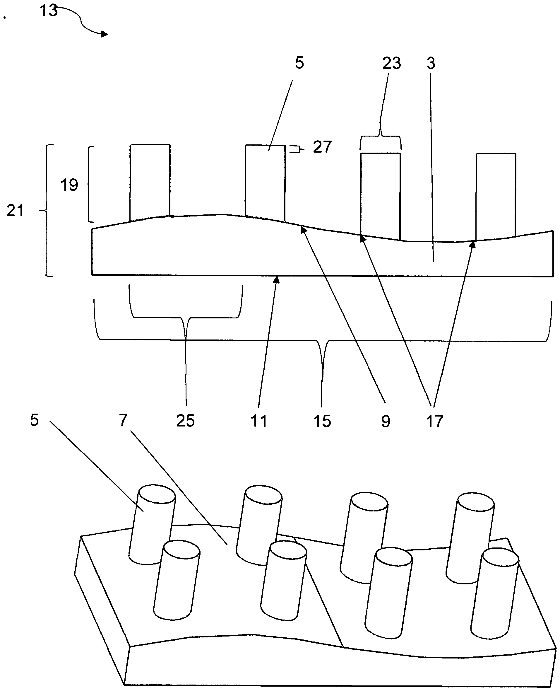
In
Wird die Sinuskurve über eine Wellenlänge 15 gemittelt verläuft diese Mittellinie parallel zur Haupterstreckungsebene 11 Die einzelnen Mikrostrukturelemente 5 verlaufen entlang eines Normalvektors dieser Haupterstreckungsebene 11. Die Mikrostrukturelemente 5 sind ein einer unterschiedlichen Phasenlage 17 angebracht. Die Abstände 21 der Endflächen der Mikrostrukturelemente 5 von der Haupterstreckungsebene 11 unterscheiden sich um die Differenz 27.If the sine curve is averaged over a
Der Einfachheit halber ist nur eine sinusförmige Krümmung 9 in einer Dimension dargestellt. Selbstverständlich sind auch Krümmungen und Wölbungen in zwei Dimensionen möglich, insbesondere wenn man mehr als zwei Unterschiedliche Abstände der Enden der Mikrostrukturelemente von der Hauptersteckungsebene vorgeben möchte.For the sake of simplicity, only a
In
In
In
Die
BezugszeichenlisteList of reference symbols
- 11
- BauteilComponent
- 3, 203, 3033, 203, 303
- GrundkörperBase body
- 5, 205, 3055, 205, 305
- MikrostrukturelementMicrostructure element
- 7, 3077, 307
- Oberflächesurface
- 99
- Krümmungcurvature
- 1111
- HaupterstreckungsebeneMain extension level
- 13, 113, 213, 31313, 113, 213, 313
- EinzelelementSingle element
- 1515
- Wellenlängewavelength
- 1717
- PhasenlagePhase position
- 19, 21919, 219
- HöheHeight
- 2121
- Abstand in z-RichtungDistance in z-direction
- 2323
- Durchmesserdiameter
- 2525
- Abstand (Pitch)Distance (Pitch)
- 2727
- Differenzdifference
- 229229
- KanteEdge
ZITATE ENTHALTEN IN DER BESCHREIBUNGQUOTES INCLUDED IN THE DESCRIPTION
Diese Liste der vom Anmelder aufgeführten Dokumente wurde automatisiert erzeugt und ist ausschließlich zur besseren Information des Lesers aufgenommen. Die Liste ist nicht Bestandteil der deutschen Patent- bzw. Gebrauchsmusteranmeldung. Das DPMA übernimmt keinerlei Haftung für etwaige Fehler oder Auslassungen.This list of documents listed by the applicant was generated automatically and is included solely for the better information of the reader. The list is not part of the German patent or utility model application. The DPMA accepts no liability for any errors or omissions.
Zitierte PatentliteraturCited patent literature
- EP 2636501 B1 [0003]EP 2636501 B1 [0003]
- US 2007/0259156 A1 [0003]US 2007/0259156 A1 [0003]
- US 20170144202 A1 [0004]US 20170144202 A1 [0004]
- US 20120177881 A1 [0005]US 20120177881 A1 [0005]
Claims (11)
Priority Applications (3)
| Application Number | Priority Date | Filing Date | Title |
|---|---|---|---|
| DE202023000325.3U DE202023000325U1 (en) | 2023-02-13 | 2023-02-13 | Superhydrophobic modular structure |
| DE102023001224.6A DE102023001224B3 (en) | 2023-02-13 | 2023-03-29 | Process for producing a modular structure with superhydrophobic properties |
| EP24401006.2A EP4414092A1 (en) | 2023-02-13 | 2024-02-09 | Modular microstructure element |
Applications Claiming Priority (1)
| Application Number | Priority Date | Filing Date | Title |
|---|---|---|---|
| DE202023000325.3U DE202023000325U1 (en) | 2023-02-13 | 2023-02-13 | Superhydrophobic modular structure |
Publications (1)
| Publication Number | Publication Date |
|---|---|
| DE202023000325U1 true DE202023000325U1 (en) | 2024-05-17 |
Family
ID=91079025
Family Applications (2)
| Application Number | Title | Priority Date | Filing Date |
|---|---|---|---|
| DE202023000325.3U Active DE202023000325U1 (en) | 2023-02-13 | 2023-02-13 | Superhydrophobic modular structure |
| DE102023001224.6A Active DE102023001224B3 (en) | 2023-02-13 | 2023-03-29 | Process for producing a modular structure with superhydrophobic properties |
Family Applications After (1)
| Application Number | Title | Priority Date | Filing Date |
|---|---|---|---|
| DE102023001224.6A Active DE102023001224B3 (en) | 2023-02-13 | 2023-03-29 | Process for producing a modular structure with superhydrophobic properties |
Country Status (1)
| Country | Link |
|---|---|
| DE (2) | DE202023000325U1 (en) |
Cited By (1)
| Publication number | Priority date | Publication date | Assignee | Title |
|---|---|---|---|---|
| CN119348834A (en) * | 2024-12-30 | 2025-01-24 | 中国空气动力研究与发展中心低速空气动力研究所 | Anti-deicing surface structure for aircraft skin |
Citations (7)
| Publication number | Priority date | Publication date | Assignee | Title |
|---|---|---|---|---|
| US20070259156A1 (en) | 2006-05-03 | 2007-11-08 | Lucent Technologies, Inc. | Hydrophobic surfaces and fabrication process |
| US20120177881A1 (en) | 2011-01-11 | 2012-07-12 | Sen-Yung Lee | Super-hydrophobic microstructure |
| EP2636501B1 (en) | 2011-05-26 | 2014-12-10 | Mitsubishi Rayon Co., Ltd. | Method for producing article having fine concavo-convex structure on surface |
| DE102014119470A1 (en) * | 2014-12-22 | 2016-06-23 | Leibniz-Institut Für Neue Materialien Gemeinnützige Gmbh | Structured surface with gradual switchable adhesion |
| US20170144202A1 (en) | 2009-02-17 | 2017-05-25 | The Board Of Trustees Of The University Of Illinois | Flexible Microstructured Superhydrophobic Materials |
| US20190133222A1 (en) * | 2017-09-28 | 2019-05-09 | Bvw Holding Ag | Device for Dynamic Fluid Pinning |
| US20190212859A1 (en) * | 2017-11-01 | 2019-07-11 | Bvw Holding Ag | Microstructured Phase Interfacial Device |
-
2023
- 2023-02-13 DE DE202023000325.3U patent/DE202023000325U1/en active Active
- 2023-03-29 DE DE102023001224.6A patent/DE102023001224B3/en active Active
Patent Citations (7)
| Publication number | Priority date | Publication date | Assignee | Title |
|---|---|---|---|---|
| US20070259156A1 (en) | 2006-05-03 | 2007-11-08 | Lucent Technologies, Inc. | Hydrophobic surfaces and fabrication process |
| US20170144202A1 (en) | 2009-02-17 | 2017-05-25 | The Board Of Trustees Of The University Of Illinois | Flexible Microstructured Superhydrophobic Materials |
| US20120177881A1 (en) | 2011-01-11 | 2012-07-12 | Sen-Yung Lee | Super-hydrophobic microstructure |
| EP2636501B1 (en) | 2011-05-26 | 2014-12-10 | Mitsubishi Rayon Co., Ltd. | Method for producing article having fine concavo-convex structure on surface |
| DE102014119470A1 (en) * | 2014-12-22 | 2016-06-23 | Leibniz-Institut Für Neue Materialien Gemeinnützige Gmbh | Structured surface with gradual switchable adhesion |
| US20190133222A1 (en) * | 2017-09-28 | 2019-05-09 | Bvw Holding Ag | Device for Dynamic Fluid Pinning |
| US20190212859A1 (en) * | 2017-11-01 | 2019-07-11 | Bvw Holding Ag | Microstructured Phase Interfacial Device |
Non-Patent Citations (2)
| Title |
|---|
| F. Burmeister et al. "5. Two-photon polymerization of inorganic-organic polymers for biomedical and microoptical applications". Optically Induced Nanostructures: Biomedical and Technical Applications, edited by Karsten König and Andreas Ostendorf, Berlin, München, Boston: De Gruyter, 2015, S. 239 – 266. * |
| R. Houbertz et al. "Two-photon polymerization of inorganic-organic hybrid polymers as scalable technology using ultra-short laser pulses." Coherence and Ultrashort Pulse Laser Emission 7, 2010, S. 583 – 608. * |
Cited By (1)
| Publication number | Priority date | Publication date | Assignee | Title |
|---|---|---|---|---|
| CN119348834A (en) * | 2024-12-30 | 2025-01-24 | 中国空气动力研究与发展中心低速空气动力研究所 | Anti-deicing surface structure for aircraft skin |
Also Published As
| Publication number | Publication date |
|---|---|
| DE102023001224B3 (en) | 2024-06-06 |
Similar Documents
| Publication | Publication Date | Title |
|---|---|---|
| DE102004041434B4 (en) | Method for producing a embossing plate for a hot-cold laminating press with three-dimensional structures | |
| EP2855119B1 (en) | Method for creating an 3d object | |
| WO2017102443A1 (en) | Method for producing a micro-lens array | |
| WO2003013827A1 (en) | Structured surfaces that show a lotus effect | |
| EP4041560A1 (en) | Method and device for producing a base layer with different degrees of hardness and workpiece with different degrees of hardness | |
| DE102023001224B3 (en) | Process for producing a modular structure with superhydrophobic properties | |
| EP3585599A1 (en) | Method for producing an optical microlens array | |
| WO2003070392A1 (en) | Surface | |
| EP1210221B1 (en) | Method for the production of a structured surface | |
| EP4414092A1 (en) | Modular microstructure element | |
| DE4310296A1 (en) | Process for producing stepped mold inserts, stepped mold inserts and molded stepped microstructure bodies with high precision | |
| WO2019193174A1 (en) | Microstructured object | |
| DE19941048A1 (en) | Surface texturing tool for embossing glass, metal or plastic surfaces to increase resistance to soiling and wetting has textured surface with nanometer size elements | |
| AT522535A2 (en) | Stamp replication device and method for producing a holding device for a stamp replication device and a stamp | |
| EP3571038A1 (en) | System and method for the production of a three-dimensional object | |
| EP3083251B1 (en) | Device and method for the production of structured surfaces | |
| DE112012007214B4 (en) | Apparatus for manufacturing a lens wafer | |
| WO2019180031A1 (en) | Method for producing and using a substrate having a functionalized surface | |
| DE102020209106B4 (en) | Method for providing an embossing element for an embossing tool, an embossing element, a use of an embossing element and an embossing tool comprising an embossing element | |
| EP3311971B1 (en) | Process for producing a plastic part with a surface structure | |
| DE19602736A1 (en) | Method and device for producing optical lenses and optical lens arrays | |
| DE10144579A1 (en) | To produce fine to micro structures and/or micro systems, a substrate film is passed between an illuminating roller and a counter roller, with a photo-setting fluid in the gap between them | |
| EP3517654B1 (en) | Method of making a mold insert with (sub)microstructures and workpiece comprising (sub)microstructures | |
| DE102011012308B4 (en) | Method for producing a structure device with topographic relief | |
| DE102009019647B4 (en) | Diffraction grating and method of manufacture |
Legal Events
| Date | Code | Title | Description |
|---|---|---|---|
| R163 | Identified publications notified | ||
| R207 | Utility model specification |