DE202021105458U1 - Device for the magnetic purification of biological samples - Google Patents
Device for the magnetic purification of biological samples Download PDFInfo
- Publication number
- DE202021105458U1 DE202021105458U1 DE202021105458.1U DE202021105458U DE202021105458U1 DE 202021105458 U1 DE202021105458 U1 DE 202021105458U1 DE 202021105458 U DE202021105458 U DE 202021105458U DE 202021105458 U1 DE202021105458 U1 DE 202021105458U1
- Authority
- DE
- Germany
- Prior art keywords
- sample vessel
- magnetic
- sample
- magnetic field
- field gradient
- Prior art date
- Legal status (The legal status is an assumption and is not a legal conclusion. Google has not performed a legal analysis and makes no representation as to the accuracy of the status listed.)
- Expired - Lifetime
Links
Images


Classifications
-
- B—PERFORMING OPERATIONS; TRANSPORTING
- B03—SEPARATION OF SOLID MATERIALS USING LIQUIDS OR USING PNEUMATIC TABLES OR JIGS; MAGNETIC OR ELECTROSTATIC SEPARATION OF SOLID MATERIALS FROM SOLID MATERIALS OR FLUIDS; SEPARATION BY HIGH-VOLTAGE ELECTRIC FIELDS
- B03C—MAGNETIC OR ELECTROSTATIC SEPARATION OF SOLID MATERIALS FROM SOLID MATERIALS OR FLUIDS; SEPARATION BY HIGH-VOLTAGE ELECTRIC FIELDS
- B03C1/00—Magnetic separation
- B03C1/005—Pretreatment specially adapted for magnetic separation
- B03C1/01—Pretreatment specially adapted for magnetic separation by addition of magnetic adjuvants
-
- G—PHYSICS
- G01—MEASURING; TESTING
- G01N—INVESTIGATING OR ANALYSING MATERIALS BY DETERMINING THEIR CHEMICAL OR PHYSICAL PROPERTIES
- G01N1/00—Sampling; Preparing specimens for investigation
- G01N1/28—Preparing specimens for investigation including physical details of (bio-)chemical methods covered elsewhere, e.g. G01N33/50, C12Q
- G01N1/34—Purifying; Cleaning
-
- B—PERFORMING OPERATIONS; TRANSPORTING
- B03—SEPARATION OF SOLID MATERIALS USING LIQUIDS OR USING PNEUMATIC TABLES OR JIGS; MAGNETIC OR ELECTROSTATIC SEPARATION OF SOLID MATERIALS FROM SOLID MATERIALS OR FLUIDS; SEPARATION BY HIGH-VOLTAGE ELECTRIC FIELDS
- B03C—MAGNETIC OR ELECTROSTATIC SEPARATION OF SOLID MATERIALS FROM SOLID MATERIALS OR FLUIDS; SEPARATION BY HIGH-VOLTAGE ELECTRIC FIELDS
- B03C1/00—Magnetic separation
- B03C1/02—Magnetic separation acting directly on the substance being separated
- B03C1/025—High gradient magnetic separators
- B03C1/031—Component parts; Auxiliary operations
- B03C1/033—Component parts; Auxiliary operations characterised by the magnetic circuit
- B03C1/0332—Component parts; Auxiliary operations characterised by the magnetic circuit using permanent magnets
-
- B—PERFORMING OPERATIONS; TRANSPORTING
- B03—SEPARATION OF SOLID MATERIALS USING LIQUIDS OR USING PNEUMATIC TABLES OR JIGS; MAGNETIC OR ELECTROSTATIC SEPARATION OF SOLID MATERIALS FROM SOLID MATERIALS OR FLUIDS; SEPARATION BY HIGH-VOLTAGE ELECTRIC FIELDS
- B03C—MAGNETIC OR ELECTROSTATIC SEPARATION OF SOLID MATERIALS FROM SOLID MATERIALS OR FLUIDS; SEPARATION BY HIGH-VOLTAGE ELECTRIC FIELDS
- B03C1/00—Magnetic separation
- B03C1/02—Magnetic separation acting directly on the substance being separated
- B03C1/28—Magnetic plugs and dipsticks
- B03C1/288—Magnetic plugs and dipsticks disposed at the outer circumference of a recipient
-
- B—PERFORMING OPERATIONS; TRANSPORTING
- B03—SEPARATION OF SOLID MATERIALS USING LIQUIDS OR USING PNEUMATIC TABLES OR JIGS; MAGNETIC OR ELECTROSTATIC SEPARATION OF SOLID MATERIALS FROM SOLID MATERIALS OR FLUIDS; SEPARATION BY HIGH-VOLTAGE ELECTRIC FIELDS
- B03C—MAGNETIC OR ELECTROSTATIC SEPARATION OF SOLID MATERIALS FROM SOLID MATERIALS OR FLUIDS; SEPARATION BY HIGH-VOLTAGE ELECTRIC FIELDS
- B03C2201/00—Details of magnetic or electrostatic separation
- B03C2201/18—Magnetic separation whereby the particles are suspended in a liquid
-
- B—PERFORMING OPERATIONS; TRANSPORTING
- B03—SEPARATION OF SOLID MATERIALS USING LIQUIDS OR USING PNEUMATIC TABLES OR JIGS; MAGNETIC OR ELECTROSTATIC SEPARATION OF SOLID MATERIALS FROM SOLID MATERIALS OR FLUIDS; SEPARATION BY HIGH-VOLTAGE ELECTRIC FIELDS
- B03C—MAGNETIC OR ELECTROSTATIC SEPARATION OF SOLID MATERIALS FROM SOLID MATERIALS OR FLUIDS; SEPARATION BY HIGH-VOLTAGE ELECTRIC FIELDS
- B03C2201/00—Details of magnetic or electrostatic separation
- B03C2201/26—Details of magnetic or electrostatic separation for use in medical or biological applications
Landscapes
- Health & Medical Sciences (AREA)
- Life Sciences & Earth Sciences (AREA)
- Engineering & Computer Science (AREA)
- Biomedical Technology (AREA)
- Molecular Biology (AREA)
- Physics & Mathematics (AREA)
- Chemical & Material Sciences (AREA)
- Analytical Chemistry (AREA)
- Biochemistry (AREA)
- General Health & Medical Sciences (AREA)
- General Physics & Mathematics (AREA)
- Immunology (AREA)
- Pathology (AREA)
- Apparatus Associated With Microorganisms And Enzymes (AREA)
- Magnetic Resonance Imaging Apparatus (AREA)
Abstract
Vorrichtung zur magnetischen Aufbereitung biologischer Proben (10), mit
wenigstens einer Einrichtung zur Erzeugung eines statischen Magnetfeldgradienten (11),
wenigstens einer Halterung (15) für Probengefäße (24), die wenigstens zwei Probengefäßaufnahmen (17,18,20,21) umfasst, wobei die Probengefäßaufnahmen (17,18,20,21) bezüglich der Einrichtung zur Erzeugung eines statischen Magnetfeldgradienten (11) in einer unterschiedlichen relativen Lage angeordnet sind.
at least one device for generating a static magnetic field gradient (11),
at least one holder (15) for sample vessels (24), which comprises at least two sample vessel receptacles (17,18,20,21), the sample vessel receptacles (17,18,20,21) relative to the device for generating a static magnetic field gradient (11) are arranged in a different relative position.
Description
Technisches Gebiettechnical field
Die vorliegende Erfindung betrifft eine Vorrichtung zur magnetischen Aufbereitung, insbesondere zur magnetischen Aufreinigung, biologischer Proben, wobei die Aufbereitung auf spezifischen Wechselwirkungen von nichtmagnetischem biologischem Material mit magnetischen Partikeln beruht.The present invention relates to a device for the magnetic preparation, in particular for the magnetic purification, of biological samples, the preparation being based on specific interactions of non-magnetic biological material with magnetic particles.
Technischer HintergrundTechnical background
Im Bereich der biologisch-medizinischen Forschung ist eine Aufreinigung von biologischem Material aus einer heterogenen Partikelsuspension für verschiedene Analysemethoden erforderlich. Dabei besteht ein großes Interesse an der Anreicherung von Zellen und einzelnen zellulären Organismen einschließlich Bakterien und Viren, aber auch von Zellfragmenten wie Proteinen, Peptiden oder Nukleinsäuren.In the field of biological-medical research, purification of biological material from a heterogeneous particle suspension is required for various analysis methods. There is a great deal of interest in the enrichment of cells and individual cellular organisms, including bacteria and viruses, but also of cell fragments such as proteins, peptides or nucleic acids.
Der Einfachheit halber wird der Begriff „Zellen“ hier im weitesten Sinne verwendet und steht für alle mehrzelligen und einzelligen Organismen, aber auch für Zellfragmente und Viren sowie für einzelne Biomoleküle wie Proteine, Peptide oder Nukleinsäuren.For the sake of simplicity, the term "cells" is used here in the broadest sense and stands for all multicellular and unicellular organisms, but also for cell fragments and viruses as well as for individual biomolecules such as proteins, peptides or nucleic acids.
Zur verbesserten Trennung oder zur Herstellung der Trennbarkeit von schwer oder nur unzureichend trennbaren biologischen Materialien steht eine Vielzahl von Markierungsmethoden zur Verfügung, die häufig auf so genannten Affinitätsreaktionen beruhen. Die gängigste Separationstechnologie basiert auf der Markierung von Zielzellen oder Zellfragmenten mit Fluoreszenzfarbstoffen oder synthetischen magnetischen Partikeln. Diese magnetische Zellseparationstechnologie zeichnet sich im Vergleich zur fluoreszenzaktivierten Zellsortierung durch ihre Einfachheit und geringen Kosten aus.A large number of labeling methods, which are often based on so-called affinity reactions, are available for improved separation or for making biological materials that are difficult or insufficiently separable. The most common separation technology is based on labeling target cells or cell fragments with fluorescent dyes or synthetic magnetic particles. This magnetic cell separation technology is characterized by its simplicity and low cost compared to fluorescence-activated cell sorting.
Die magnetische Separation erfolgt durch Markierung von Zielmaterialien mit rezeptor- bzw. ligandenkonjugierten magnetischen Partikeln. Der Begriff Zielmaterial bezeichnet alle Substanzen und molekularen Strukturen, die sich mit dem biologischen Material verbinden können, um ein spezifisches Bindungspaar zu bilden.Magnetic separation is achieved by labeling target materials with receptor or ligand-conjugated magnetic particles. The term target material refers to all substances and molecular structures that can bind to the biological material to form a specific binding pair.
Der Begriff spezifisches Bindungspaar steht für ein Paar oder eine Kombination von Substanzen, die eine Bindungstendenz aufweisen, und umfasst Elemente wie zelluläre Komponenten, biospezifische Liganden und Rezeptoren. In diesem Sinne erfolgt die Markierung eines Zielmaterials durch die Assoziation spezifischer Bindungspaare, bestehend aus Ligand und Rezeptor. Der Begriff „Ligand“ bezeichnet die an das Zielmaterial gebundene Komponente, die zu einer spezifischen Bindung fähig ist und Antigene oder Haptene umfasst, die durch mindestens ein Epitop oder andere charakteristische Determinanten definiert sind. Der Begriff „Rezeptor“ bezeichnet das Markierungsziel oder eine Gruppe davon mit biospezifischer Affinität zu einem exklusiven Liganden. Mögliche Rezeptoren können monoklonale Antikörper oder Fragmente davon, spezifische Bindungsproteine wie Protain A oder G, das Biotin-Streptavidin-Bindungspaar, Aptamere, Nukleinsäuren usw. sein. Vorzugsweise ist die bio-spezifische Bindung nicht-kovalent, was eine hohe Bindungskinetik und möglicherweise Reversibilität voraussetzt.The term specific binding pair means a pair or combination of substances that exhibit a tendency to bind and includes such elements as cellular components, biospecific ligands and receptors. In this sense, the labeling of a target material takes place through the association of specific binding pairs consisting of ligand and receptor. The term "ligand" denotes the component bound to the target material, capable of specific binding and comprising antigens or haptens defined by at least one epitope or other characteristic determinant. The term "receptor" refers to the labeling target or group thereof with biospecific affinity for an exclusive ligand. Possible receptors can be monoclonal antibodies or fragments thereof, specific binding proteins like protein A or G, the biotin-streptavidin binding pair, aptamers, nucleic acids and so on. Preferably, the bio-specific binding is non-covalent, implying high binding kinetics and possibly reversibility.
Zur Beschreibung des Stands der Technik zur Herstellung von magnetischen Partikeln, die für die magnetische Zellseparationstechnologie geeignet sind, sei auf die Patente
Generell lässt sich die magnetische Trenntechnik in intrinsische und externe Verfahren unterteilen. Wie bereits erwähnt, erzeugen magnetische Partikel, die kleiner als 100 nm sind, in Gegenwart einer externen Magnetfeldquelle nur sehr geringe magnetische Momente. Die geringe Partikelgröße ist jedoch mit einem günstigen Verhältnis zwischen reaktiver Oberfläche und Partikelvolumen bzw. der Partikelmenge verbunden. Folglich sind für die magnetische Fraktionierung unter Verwendung von so genannten Nanopartikeln mit Durchmessern zwischen 30 nm und 100 nm sogenannte Hochgradienten-Magnetseparationssysteme erforderlich, die beispielsweise in den Patenten
Kommerziell verfügbare intrinsische Zellseparationssysteme für die allgemeine Zellseparation unter Verwendung von magnetischen Nanopartikeln mit einem Durchmesser von 50 nm wurden von der Firma Miltenyi AG entwickelt. Dabei wird eine so genannte magnetische Trennsäule verwendet, die aus einer ferromagnetischen Matrix in einem nicht-magnetischen Behälter besteht. Zum Zweck der magnetischen Trennung wird die Trennsäule in ein starkes äußeres Magnetfeld gebracht. In der Trennkammer sind hohe Magnetfeldgradienten von bis zu 100 Tesla/cm zu erwarten. Das Verfahren ist im Vergleich zu externen magnetischen Trennverfahren kompliziert, verhindert schnelle Protokolle, erschwert die Automatisierung und erhöht die Kosten. Darüber hinaus erzeugt die magnetische Trennmatrix eine große reaktive Oberfläche, die Stress auf lebensfähige Zellen ausüben oder die unspezifische Bindung von Zellen an die reaktive Oberfläche erhöhen kann.Commercially available intrinsic cell separation systems for general cell separation using magnetic nanoparticles with a diameter of 50 nm were developed by Miltenyi AG. A so-called magnetic separation column is used, which consists of a ferromagnetic matrix in a non-magnetic container. For the purpose of magnetic separation, the separation column is placed in a strong external magnetic field. High magnetic field gradients of up to 100 Tesla/cm are to be expected in the separation chamber. The process is complicated compared to external magnetic separation processes, preventing rapid protocols, making automation difficult and increasing costs. In addition, the magnetic separation matrix creates a large reactive surface area that can induce stress on viable cells or increase non-specific binding of cells to the reactive surface.
Um die Nachteile von Magnetseparationssäulen zu vermeiden und die Vorteile der Verwendung von Nanopartikeln zu nutzen, wurden externe Hochgradienten-Magnetseparationssysteme entwickelt. Dabei wurde der Schwerpunkt auf externe spezialisierte Magnetkonfigurationen gelegt, wie zum Beispiel die Quadrupol- oder Hexapolkonfiguration, wie sie zum Beispiel im Patent
Die Verwendung von Magnetpartikeln mit einem Durchmesser von mehr als 500 nm ermöglicht den Einsatz einer sehr einfachen und weniger kostspieligen Magnetseparation, bei der ein Inkubationsbehälter neben einem einfachen Permanentmagneten aufgestellt wird. Kommerziell erhältliche Systeme werden zum Beispiel von Dynal Inc. unter der Bezeichnung Dynal MPC1 angeboten.The use of magnetic particles larger than 500 nm in diameter allows the use of a very simple and less expensive magnetic separation, where an incubation vessel is placed next to a simple permanent magnet. Commercially available systems are offered, for example, by Dynal Inc. under the designation Dynal MPC1.
Ein wichtiger Aspekt bei der Weiterentwicklung von auf Magnetpartikeln basierenden Separationssystemen ist die Verbesserung der Anreicherungsqualität, was im Wesentlichen bedeutet, dass der Verlust der gewünschten Zellen verringert und ihre Reinheit maximiert wird. Der Anreicherungsprozess besteht in der Regel aus einer Inkubationsphase zur magnetischen Markierung des Zielmaterials und der anschließenden magnetischen Trennung. Üblicherweise wird die Inkubation in Ruhe durchgeführt, wenn Partikel verwendet werden, die nicht größer als 150 nm sind, oder gelegentliches Mischen, wenn größere Partikel mit Sedimentationstendenz verwendet werden.An important aspect in the advancement of magnetic particle-based separation systems is to improve the enrichment quality, which essentially means reducing the loss of the desired cells and maximizing their purity. The enrichment process usually consists of an incubation phase for magnetic labeling of the target material and subsequent magnetic separation. Usually, incubation is carried out quietly when using particles no larger than 150 nm, or with occasional mixing when using larger particles with a tendency to sedimentation.
Das Patent
Magnetische Partikel lassen sich in Abhängigkeit ihrer Größe grob in Nano- und Mikropartikel eingruppieren. Magnetische Nanopartikel (30 nm bis 150 nm) werden auf Grund ihrer Eigenschaften auch als Ferrofluide bezeichnet. Derartige Partikelsuspensionen bilden stabile Kolloide aus, unterliegen der Brownschen Molekularbewegung und sedimentieren auch über längere Zeiträume (Monate bis Jahre) nicht. Nanopartikel sind daher sehr beweglich in Lösung und bilden hohe reaktive Oberflächen aus, versprechen demnach im Vergleich zu Mikropartikeln (> 0.2 um) effizientere magnetische Markeriung und Abscheidung und schnellere Reaktionskinetiken, wie zum Beispiel erwähnt in dem Patent
In der internationalen Patentanmeldung
Der vorliegenden Erfindung liegt das technische Problem zugrunde, die in
Lösung des technischen ProblemsSolution of the technical problem
Gelöst wird dieses technische Problem durch die Vorrichtung zur magnetischen Aufbereitung, insbesondere zur magnetischen Aufreinigung, biologischer Proben mit den Merkmalen des vorliegenden Anspruchs 1. Vorteilhafte Weiterbildungen der vorliegenden Erfindung sind Gegenstand der abhängigen Ansprüche.This technical problem is solved by the device for magnetic processing, in particular for magnetic purification, of biological samples with the features of present claim 1. Advantageous developments of the present invention are the subject matter of the dependent claims.
Der vorliegenden Erfindung liegt die Beobachtung zugrunde, dass bereits eine sehr gute Spezifizität der Bindung magnetischer Partikel an gewünschte Zellen erzielt werden kann, wenn zumindest die Stärke des Magnetfeldgradienten in einzelnen Prozessschritten variiert wird, während die durch Mischung statt durch eine variable Rotation auch durch kurze Mischvorgänge, beispielsweise mit Hilfe eines Vortex-Mischers, außerhalb des Magnetfeldes realisiert werden kann.The present invention is based on the observation that a very good specificity of the binding of magnetic particles to desired cells can already be achieved if at least the strength of the magnetic field gradient is varied in individual process steps, while the mixing instead of variable rotation is also achieved by short mixing processes , for example with the help of a vortex mixer, can be realized outside the magnetic field.
Die vorliegende Erfindung betrifft demnach eine Vorrichtung zur magnetischen Aufbereitung, insbesondere zur magnetischen Aufreinigung, biologischer Proben mit wenigstens einer Einrichtung zur Erzeugung eines statischen Magnetfeldgradienten, wenigstens einer Halterung für Probengefäße, die wenigstens zwei Probengefäßaufnahmen umfasst, wobei die Probengefäßaufnahmen bezüglich der Einrichtung zur Erzeugung eines statischen Magnetfeldgradienten in einer unterschiedlichen relativen Lage angeordnet sind. Unter einer unterschiedlichen relativen Lage ist im vorliegenden Zusammenhang zu verstehen, dass sich das durch die Einrichtung zur Erzeugung eines statischen Magnetfeldgradienten erzeugte Magnetfeld im Bereich der wenigstens zwei Probegefäßaufnahme in wenigstens einem Parameter unterscheidet. Sollte beispielsweise die Vorrichtung und insbesondere die Einrichtung zur Erzeugung eines statischen Magnetfeldgradienten gewisse Symmetrien aufweisen, so wäre eine bezüglich dieser Symmetrien symmetrische Anordnung der beiden Probengefäßaufnahmen keine „unterschiedliche relative Lage“ im Sinne der vorliegenden Erfindung.The present invention therefore relates to a device for magnetic processing, in particular for magnetic purification, of biological samples with at least one device for generating a static magnetic field gradient, at least one holder for sample vessels, which comprises at least two sample vessel receptacles, the sample vessel receptacles being relative to the device for generating a static Magnetic field gradients are arranged in a different relative position. In the present context, a different relative position means that the magnetic field generated by the device for generating a static magnetic field gradient differs in at least one parameter in the region of the at least two sample vessel receptacles. If, for example, the device and in particular the device for generating a static magnetic field gradient have certain symmetries, a symmetrical arrangement of the two sample vessel receptacles with respect to these symmetries would not be a “different relative position” within the meaning of the present invention.
Vorzugsweise sind die wenigstens zwei Probengefäßaufnahmen bezüglich der Einrichtung zur Erzeugung eines statischen Magnetfeldgradienten so angeordnet, dass sich am Ort der in die Probengefäßaufnahmen eingesetzten Probengefäße das Magnetfeld in Betrag und/oder Gradient unterscheidet. Somit können Probengefäße in unterschiedlichen Prozessschritten einem Magnetfeld ausgesetzt werden, das stärker oder schwächer und/oder einen größeren oder einen kleineren Magnetfeldgradienten aufweist.The at least two sample vessel receptacles are preferably arranged with respect to the device for generating a static magnetic field gradient in such a way that the magnetic field differs in magnitude and/or gradient at the location of the sample vessels inserted into the sample vessel receptacles. Thus, in different process steps, sample vessels can be exposed to a magnetic field that is stronger or weaker and/or has a larger or smaller magnetic field gradient.
Dazu ist es vorteilhaft, wenn die Probengefäße zwischen den Probengefäßaufnahmen gewechselt werden können, d. h. die Probengefäßaufnahmen der Vorrichtung sind vorzugsweise so ausgebildet, dass sie dieselben Probengefäße aufnehmen können.For this purpose, it is advantageous if the sample vessels can be changed between the sample vessel receptacles, i. H. the sample vessel receptacles of the device are preferably designed in such a way that they can hold the same sample vessels.
Zur Erzeugung des Magnetfeldgradienten können unterschiedliche physikalische Techniken verwendet werden. Beispielsweise kann die Einrichtung zur Erzeugung eines Magnetfeldgradienten wenigstens einen Elektromagneten umfassen. In diesem Fall umfasst die Vorrichtung vorzugsweise auch eine Stromversorgung für den Elektromagneten, beispielsweise eine eingebaute Batterie oder einen Akkumulator oder auch einen elektrischen Netzanschluss. Besonders bevorzugt umfasst die Einrichtung zur Erzeugung eines Magnetfeldgradienten wenigstens einen Permanentmagneten, da die erfindungsgemäße Vorrichtung in diesem Fall keinerlei Energieversorgung benötigt und besonders kostengünstig ausgeführt werden kann.Different physical techniques can be used to generate the magnetic field gradient. For example, the device for generating a magnetic field gradient can comprise at least one electromagnet. In this case, the device preferably also includes a power supply for the electromagnet, for example a built-in battery or an accumulator or an electrical mains connection. The device for generating a magnetic field gradient particularly preferably comprises at least one permanent magnet, since the device according to the invention does not require any energy supply in this case and can be implemented particularly cost-effectively.
In einer bevorzugten Ausführungsform ist der Permanentmagnet als, im Wesentlichen stabförmiger Dipolmagnet mit Luftspalt ausgebildet. Bei einer solchen Anordnung entsteht in der Umgebung des Luftspaltes ein besonders starker Magnetfeldgradient.In a preferred embodiment, the permanent magnet is designed as an essentially rod-shaped dipole magnet with an air gap. With such an arrangement, a particularly strong magnetic field gradient occurs in the vicinity of the air gap.
In diesem Fall sind die wenigstens zwei Probengefäßaufnahmen vorzugsweise so angeordnet, dass sich eine erste Probengefäßaufnahme nahe an dem Luftspalt des Dipolmagneten befindet, also an einem Ort mit einem hohen Magnetfeldgradienten. Die zweite Probengefäßaufnahme kann dann beispielsweise an einer Seitenfläche des Dipolmagneten angeordnet sein, beispielsweise in der Mitte eines Vollmagnetabschnitts des Dipolmagneten. Am Ort der zweiten Probengefäßaufnahme läge dann beispielsweise ein geringerer Magnetfeldgradient, aber, je nach Abstand von der Seitenfläche, gegebenenfalls ein höheres absolutes Magnetfeld als am Ort der ersten Probengefäßaufnahme vor.In this case, the at least two sample vessel receptacles are preferably arranged in such a way that a first sample vessel receptacle is located close to the air gap of the dipole magnet, ie at a location with a high magnetic field gradient. The second sample vessel receptacle can then be arranged, for example, on a side face of the dipole magnet, for example in the middle of a full magnet section of the dipole magnet. At the location of the second sample vessel receptacle, for example, there would then be a lower magnetic field gradient but, depending on the distance from the side surface, there might be a higher absolute magnetic field than at the location of the first sample vessel receptacle.
Vorzugsweise ist wenigstens eine dritte Probengefäßaufnahme vorgesehen, die in einem größeren Abstand von dem Dipolmagneten als die erste und zweite Probengefäßaufnahme angeordnet ist. Am Ort der dritten Probengefäßaufnahme liegt dann sowohl ein geringeres Magnetfeld als auch ein geringerer Magnetfeldgradient vor. Es versteht sich, dass weitere Probengefäßaufnahmen in der erfindungsgemäßen Vorrichtung vorgesehen sein können.At least one third sample vessel receptacle is preferably provided, which is arranged at a greater distance from the dipole magnet than the first and second sample vessel receptacle. At the location of the third sample vessel receptacle there is then both a lower magnetic field and a lower magnetic field gradient. It goes without saying that further sample vessel receptacles can be provided in the device according to the invention.
Konstruktiv kann die erfindungsgemäße Vorrichtung in unterschiedlicher Weise realisiert werden. In einer Ausführungsform umfasst die erfindungsgemäße Vorrichtung ein Gehäuse, das die Einrichtung zur Erzeugung eines Magnetfeldgradienten umschließt. Das Gehäuse besteht vorzugsweise aus nichtmagnetischem Material, beispielsweise aus Aluminium oder einem Kunststoffmaterial. Die Oberseite des Gehäuses bildet dann die Halterung für Probengefäße und die Probengefäßaufnahmen können dabei als Öffnungen auf der Oberseite ausgebildet sein. Die Oberseite des Gehäuses kann auch als Gehäusedeckel ausgebildet sein, welcher mit einer Gehäusebasis fest verbunden, beispielsweise verklebt, verschraubt, verklipst oder verschweißt werden kann. Der Gehäusedeckel kann auch abnehmbar ausgebildet sein, so dass bei Bedarf ein einfacher Zugang zu der Einrichtung zur Erzeugung eines Magnetfeldgradienten besteht.Structurally, the device according to the invention can be realized in different ways. In one embodiment, the device according to the invention comprises a housing which encloses the device for generating a magnetic field gradient. The housing is preferably made of non-magnetic material, for example aluminum or a plastic material. The upper side of the housing then forms the holder for sample vessels, and the sample vessel receptacles can be designed as openings on the upper side. The upper side of the housing can also be designed as a housing cover, which can be firmly connected to a housing base, for example glued, screwed, clipped or welded. The housing cover can also be designed to be removable, so that there is easy access to the device for generating a magnetic field gradient if required.
Die Öffnungen auf der Oberseite des Gehäuses sind vorzugsweise zur Aufnahme von Reaktionsgefäßen ausgebildet, die typischerweise Fluide in der Größenordnung von Mikro- bis Millilitern aufnehmen können. Auch die Reaktionsgefäße bestehen typischerweise aus nichtmagnetischen Materialien, beispielsweise aus Kunststoffmaterialien, die gegenüber den eingesetzten Fluiden inert sind.The openings on the top of the housing are preferably configured to receive reaction vessels, which typically can hold fluids on the order of microliters to milliliters. The reaction vessels are also typically made of non-magnetic materials, for example plastic materials, which are inert to the fluids used.
Die Oberseite des Gehäuses kann geeignete Beschriftungen an den Öffnungen aufweisen, so dass der Nutzer eine einfache Zuordnung der jeweiligen Öffnung zu entsprechenden vorgegebenen Protokollschritten einer Aufreinigungsprozedur vornehmen kann.The upper side of the housing can have suitable inscriptions on the openings, so that the user can easily allocate the respective opening to corresponding predetermined protocol steps of a purification procedure.
In einer Ausführungsform der Erfindung ist zumindest eine der Öffnungen zur Aufnahme der Probengefäße mit einer abgeschrägten Innenfläche versehen, deren Kontur an den Außenumfang des Probengefäßes angepasst ist. Bei einer im Wesentlichen ebenen Oberseite der erfindungsgemäßen Vorrichtung weist eine typische Öffnung vertikale Innenflächen auf, d. h. die Innenfläche bildet mit der Oberseite im Wesentlichen einen rechten Winkel, so dass die Probengefäße ebenfalls vertikal in die Vorrichtung eingesetzt werden. Unter einer abgeschrägten Innenfläche ist demgegenüber eine Innenfläche der Öffnung zu verstehen, die mit der Oberseite des Gehäusedeckels einen von 90 Grad abweichenden Winkel bildet, so dass das Probengefäß entsprechend schräg in die Öffnung eingesetzt wird. Typische Probengefäße, die mit der erfindungsgemäßen Vorrichtung verwendet werden, weisen einen zylindrischen Hals (üblicherweise mit verschließbarem Deckel) und eine konische Spitze auf. Das Probenfluid befindet sich typischerweise im konischen, unteren Bereich des Probengefäßes. Durch ein schräges Einsetzen der Probengefäße, das durch die abgeschrägte Innenfläche der Öffnung der Probenaufnahme gewährleistet wird, kann die Spitze des Probengefäßes optimaler im Bereich des maximalen Magnetfeldgradienten positioniert werden als dies bei einer vertikalen Orientierung des Probengefäßes möglich wäre. Vorzugsweise ist die Abschrägung der Innenfläche der Öffnung hinsichtlich des Winkels zur Oberseite der Vorrichtung an den entsprechenden Konuswinkel der üblicherweise eingesetzten Probengefäße angepasst, so dass die zum Spalt des Dipolmagneten gerichtete Fläche des Konus des Probengefäßes im Wesentlichen vertikal orientiert ist. Dadurch befindet sich zumindest ein Großteil des Probenfluides im Bereich eines homogenen Magnetfeldgradienten, und insbesondere, wenn es sich bei der Probenaufnahme um die unmittelbar am Spalt des Dipolmagneten angeordnete Probenaufnahme handelt, im Bereich des maximalen Magnetfeldgradienten.In one embodiment of the invention, at least one of the openings for receiving the sample vessels is provided with a beveled inner surface, the contour of which is adapted to the outer circumference of the sample vessel. With a substantially planar top surface of the device of the present invention, a typical opening will have vertical interior surfaces, e.g. H. the inner surface essentially forms a right angle with the upper side, so that the sample vessels are also inserted vertically into the device. In contrast, a beveled inner surface is to be understood as meaning an inner surface of the opening which forms an angle deviating from 90 degrees with the upper side of the housing cover, so that the sample vessel is inserted into the opening at a corresponding angle. Typical sample vessels used with the device according to the invention have a cylindrical neck (usually with a closable lid) and a conical tip. The sample fluid is typically in the conical, lower area of the sample vessel. By inserting the sample vessels at an angle, which is ensured by the slanted inner surface of the opening of the sample holder, the tip of the sample vessel can be positioned more optimally in the area of the maximum magnetic field gradient than would be possible with a vertical orientation of the sample vessel. The bevel of the inner surface of the opening is preferably adapted to the corresponding cone angle of the sample vessels usually used with regard to the angle to the upper side of the device, so that the surface of the cone of the sample vessel facing the gap of the dipole magnet is oriented essentially vertically. As a result, at least a large part of the sample fluid is in the area of a homogeneous magnetic field gradient, and in particular when the sample holder is the sample holder arranged directly at the gap of the dipole magnet, in the area of the maximum magnetic field gradient.
Die wenigstens eine Halterung der erfindungsgemäßen Vorrichtung kann außerdem Behälteraufnahmen für Reaktionsfluidbehälter umfassen. Diese sind vorzugsweise an Orten der Vorrichtung ausgebildet, an denen nur noch eine geringe Magnetfeldstärke herrscht. Beispielsweise können die Behälteraufnahmen für Reaktionsfluidbehälter als Öffnungen ausgebildet sein, die am Außenumfang der Oberseite des Gehäuses der Vorrichtung ausgespart sind.The at least one holder of the device according to the invention can also include container receptacles for reaction fluid containers. These are preferably formed at locations of the device where there is only a low magnetic field strength. For example, the container receptacles for reaction fluid containers can be designed as openings that are cut out on the outer circumference of the upper side of the housing of the device.
Die erfindungsgemäße Vorrichtung betrifft außerdem ein Set zur magnetischen Aufreinigung biologischer Proben umfassend eine Vorrichtung zur magnetischen Aufreinigung biologischer Proben der oben beschriebenen Art, sowie magnetische oder magnetisierbare Partikel, insbesondere magnetische oder magnetisierbare Microbeads, sowie ein auf ein spezifisches Aufreinigungsproblem ausgerichtetes Protokoll zur magnetischen Aufreinigung biologischer Proben. Die magnetischen oder magnetisierbaren Partikel/Microbeads haben typischerweise einen Durchmesser im Bereich von 100 bis 500 nm.The device according to the invention also relates to a set for the magnetic purification of biological samples comprising a device for the magnetic purification of biological samples of the type described above, as well as magnetic or magnetizable particles, in particular magnetic or magnetizable microbeads, and a protocol for the magnetic purification of biological samples geared to a specific purification problem . The magnetic or magnetizable particles/microbeads typically have a diameter in the range from 100 to 500 nm.
Detaillierte Beschreibung eines AusführungsbeispielsDetailed description of an embodiment
Die Erfindung wird im Folgenden unter Bezugnahme auf ein in den vorliegenden Zeichnungen dargestelltes Ausführungsbeispiel näher erläutert.The invention is explained in more detail below with reference to an exemplary embodiment illustrated in the present drawings.
In den Figuren zeigen:
-
1 eine perspektivische Ansicht einer erfindungsgemäßen Vorrichtung zur magnetischen Aufreinigung biologischer Proben; -
2 die Ansicht der1 , wobei zusätzlich verdeckte Linien dargestellt sind; -
3 eine Draufsicht auf die Vorrichtung der1 ; und -
4 die Ansicht der3 , wobei zusätzliche verdeckte Linien dargestellt sind.
-
1 a perspective view of a device according to the invention for the magnetic purification of biological samples; -
2 the view of1 , where additional hidden lines are shown; -
3 a top view of the device1 ; and -
4 the view of3 , with additional hidden lines shown.
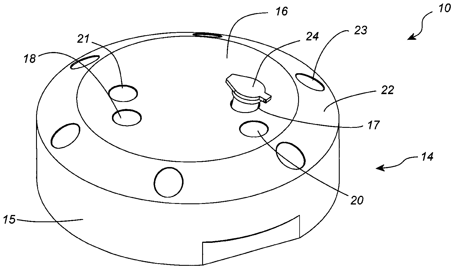
In den
In den Darstellungen der
Beispiele:Examples:
Die Verwendung der in den
In den folgenden Beispielen wird im Beispiel 1 eine bereits vorgereinigte Zellfraktion zwecks positiver Selektion von seltenen hematopoietischen Stammzellen aufbereitet. Im Beispiel 2 wird mit Vollblut zwecks negativer Selektion von sehr seltenen nicht-hematopoietischen Zellen gearbeitet und erfordert zwei Durchgänge der magnetischen Aufbereitung mit einer dazwischengeschalteten Lyse der roten Blutkörperchen.In the following examples, in example 1, an already pre-cleaned cell fraction is prepared for the purpose of positive selection of rare hematopoietic stem cells. Example 2 uses whole blood for negative selection of very rare non-hematopoietic cells and requires two passes of magnetic processing with red blood cell lysis in between.
Beispiel 1:Example 1:
Materialien:
- - Inkubationspufferlösung: iso-osmolare phosphatgepufferte Lösung, ergänzt mit 3% fötalem Rinderserum;
- - Waschlösung: iso-osmolare phosphatgepufferte Lösung;
- - Erythrozyten-Lysepuffer: 154 mM NH4CI, 10 mM NaHCO3, 2 mM EDTA;
- - Magnetvorrichtung: Aluminium-eingehauster Neodym-Magnet Typ 2: 0,52 Tesla, zwei gepaarte quadratische Dipolmagnete in einer Anordnung von 30mmx30mmx30mm pro Einheit;
- - Mikrozentrifuge 1.5ml Plastikbehälter für die Inkubation;
- - 1-ml-Plastikspritze;
- - Anti-CD34 Kit bestehend aus superparamagnetische Partikel (Mikrobeads), reaktiv gegen Biotin und Anti-CD34-Antikoerper konjugiert mit Biotin (SanoLibio GmbH, München, Deutschland);
- - Vollblut von gesunden erwachsenen Spendern, das höchstens 24 Stunden lang in Natriumheparin-Blutkonserven gelagert wurde.
- - Incubation buffer solution: iso-osmolar phosphate buffered solution supplemented with 3% fetal bovine serum;
- - washing solution: iso-osmolar phosphate buffered solution;
- - Erythrocyte lysis buffer: 154mM NH4Cl, 10mM NaHCO3, 2mM EDTA;
- - Magnet device: aluminum cased neodymium magnet Type 2: 0.52 Tesla, two paired square dipole magnets in a 30mmx30mmx30mm array per unit;
- - Microcentrifuge 1.5ml plastic container for incubation;
- - 1 ml plastic syringe;
- - Anti-CD34 kit consisting of superparamagnetic particles (microbeads) reactive against biotin and anti-CD34 antibodies conjugated with biotin (SanoLibio GmbH, Munich, Germany);
- - Whole blood from healthy adult donors stored in sodium heparin banked blood for a maximum of 24 hours.
Verfahren:Procedure:
Vor der Anreicherung der Leukozyten aus Vollblut wurden die Erythrozyten, wie dem Fachmann bekannt, mit geeigneten Lysepuffern (RBC-Lysepuffer) lysiert und die gereinigten Leukozyten durch Zentrifugation konzentriert. Die gereinigten Leukozyten wurden dann mit dem Inkubationspuffer für 5 Minuten bei Raumtemperatur inkubiert.Before the enrichment of the leukocytes from whole blood, the erythrocytes were lysed, as is known to those skilled in the art, with suitable lysis buffers (RBC lysis buffer) and the cleaned leukocytes were concentrated by centrifugation. The purified leukocytes were then incubated with the incubation buffer for 5 minutes at room temperature.
Die weiteren Prozessschritte wurden manuell oder nach dem neuen Verfahren und unter Verwendung der erfindungsgemäßen Vorrichtung durchgeführt. In allen Proben wurden anti-CD34-reaktive Antikörper mit 3×10⁷ aufbereiteten Leukozyten gemischt.
- Schritt 1: Einstellung einer vorgegebenen Zellsuspensionskonzentration und Befüllen eines Probengefäßes 24,
- Schritt 2: Einsetzen des Probengefäßes 24 in
die vierte Probengefäßaufnahme 21, Zugabe von magnetischen Microbeads, - Schritt 3 kurze Vortex-Mischung des Probengefäßes 24 außerhalb der Vorrichtung,
- Schritt 4: Wiedereinsetzen des Probengefäßes 24 in
die zweite Probengefäßaufnahme 18 und magnetische Inkubation bei geschlossenem Probengefäß, gegebenenfalls zwischenzeitliches Vortex-Mischen außerhalb der Vorrichtung, - Schritt 5: Einsetzten des Probengefäßes 24 in die erste
Probengefäßaufnahme 17, Waschen der Teilchenfraktion durch Entfernen des Überstandes und Zugabe einer Waschlösung (z.B. PBS) zur magnetischen Fraktion im magnetischen Feld; - Schritt 6: Magnetische Trennung während das Probengefäß in der ersten Probengefäßaufnahme 17 verbleibt. Die gewünschten Zellen befinden sich in der magnetischen Fraktion.
- Step 1: setting a specified cell suspension concentration and filling a
sample vessel 24, - Step 2: inserting the
sample vessel 24 into the fourthsample vessel receptacle 21, adding magnetic microbeads, - Step 3 short vortex mixing of the
sample vessel 24 outside the device, - Step 4: reinserting the
sample vessel 24 into the secondsample vessel receptacle 18 and magnetic incubation with the sample vessel closed, if necessary intermediate vortex mixing outside the device, - Step 5: inserting the
sample vial 24 into the firstsample vial receptacle 17, washing the particle fraction by removing the supernatant and adding a washing solution (eg, PBS) to the magnetic fraction in the magnetic field; - Step 6: Magnetic separation while the sample vessel remains in the first
sample vessel receptacle 17. The desired cells are in the magnetic fraction.
Beispiel 2:Example 2:
Die Verwendung der erfindungsgemäßen Vorrichtung wird im Folgenden anhand eines vereinfachten Protokolls für die Aufreinigung von nicht-hematopoetischen Zielblutzellen mittels negativer Selektion direkt aus einer Vollblutprobe unter Verwendung reaktiver magnetischer anti-CD45-Partikel und prozesslich integrierter Lyse der roten Blutzellen erläutert.The use of the device according to the invention is explained below using a simplified protocol for the purification of non-hematopoietic target blood cells by means of negative selection directly from a whole blood sample using reactive magnetic anti-CD45 particles and process-integrated lysis of the red blood cells.
Materialien:Materials:
wie beschrieben in Beispiel 1, allerdings unter Verwendung superparamagnetische Partikel, die gegen CD45 reaktiv sind, konjugiert mit Anti-CD45 Antikörpern (SanoLibio GmbH, München, Deutschland).as described in Example 1, but using superparamagnetic particles reactive against CD45 conjugated with anti-CD45 antibodies (SanoLibio GmbH, Munich, Germany).
Verfahren:Procedure:
Maximal 1 mL Vollblut wird zur manuellen Abreicherung der Leukozyten bzw. Anreicherung seltener Zellen aus anti-koagulierten frischen Vollblut mit den Mikrobeads dem neuen Verfahren folgend und unter Verwendung der erfindungsgemäßen Vorrichtung direkt inkubiert und die darin enthaltenen magnetisierten Zellen anschließend separiert. Im Anschluss daran, werden die Erythrozyten, wie dem Fachmann bekannt mit geeigneten Lysepuffern (RBC-Lysepuffer) lysiert und die gereinigte Zellsuspension durch Zentrifugation konzentriert. Zum Erreichen einer annehmbaren Anreicherungseffizienz erfolgt ein zweiter Depletionsschritt.
- Schritt 1: Einstellen des mit Vollblut beladenen Probengefäßes 24 in
die vierte Probengefäßaufnahme 21, Zugabe von magnetischen Microbeads; - Schritt 2: kurze Vortex-Mischung des Probengefäßes 24 außerhalb der Vorrichtung
- Schritt 3: Wiedereinsetzen des Probengefäßes 24 in
die zweite Probengefäßaufnahme 18 und magnetische Inkubation bei geschlossenem Probengefäß, gegebenenfalls zwischenzeitliches Vortex-Mischen außerhalb der Vorrichtung; - Schritt 4: Einsetzten des Probengefäßes 24 in die erste
Probengefäßaufnahme 17, Waschen der Teilchenfraktion durch Entfernen bzw. Sammeln des Überstandes und Zugabe eines Waschpuffers (z.B. PBS) im magnetischen Feld (Überstände in einem separaten Behälter zusammenführen); - Schritt 5: Magnetische Trennung der gesammelten Überstände während das neue Probengefäß in der ersten Probengefäßaufnahme 17 wieder eingeführt wird;
- Schritt 6: Sammeln des Überstandes (Schritt 5) und Überführung zur Lyse der Erythrozyten in entsprechenden Lysepuffer;
- Schritt 7: Einstellung einer vorgegebenen Zellsuspensionskonzentration durch Zentrifugation und Durchführung einer zweiten Aufreinigung analog Beispiel 1 (Schritt 1-4) und folgend der Schritte 4 und 5 in diesem Beispiel. Allerdings befinden sich die gewünschten Zellen im Beispiel 2 in der nicht-magnetischen Fraktion.
- Step 1: placing the
sample vessel 24 loaded with whole blood in the fourthsample vessel receptacle 21, adding magnetic microbeads; - Step 2: briefly vortex mix the
sample vessel 24 outside of the device - Step 3: reinsertion of the
sample vessel 24 into the secondsample vessel receptacle 18 and magnetic incubation with the sample vessel closed, if necessary intermediate vortex mixing outside of the device; - Step 4: inserting the
sample vessel 24 into the firstsample vessel receptacle 17, washing the particle fraction by removing or collecting the supernatant and adding a washing buffer (eg PBS) in the magnetic field (supernatants combined in a separate container); - Step 5: Magnetic separation of the collected supernatants while the new sample vial is reinserted into the first
sample vial receptacle 17; - Step 6: collecting the supernatant (step 5) and transferring it to the appropriate lysis buffer for lysis of the erythrocytes;
- Step 7: Setting a given cell suspension concentration by centrifugation and carrying out a second purification analogous to example 1 (steps 1-4) and following steps 4 and 5 in this example. However, in Example 2, the desired cells are in the non-magnetic fraction.
BezugszeichenlisteReference List
- 1010
- Vorrichtung zur magnetischen Aufbereitung biologischer ProbenDevice for the magnetic processing of biological samples
- 1111
- Einrichtung zur Erzeugung eines statischen MagnetfeldgradientenDevice for generating a static magnetic field gradient
- 1212
- Dipolmagnetdipole magnet
- 12a12a
- Vollmagnetabschnitt des DipolmagnetenFull magnet section of the dipole magnet
- 12b12b
- Vollmagnetabschnitt des DipolmagnetenFull magnet section of the dipole magnet
- 1313
- Luftspalt des Dipolmagnetenair gap of the dipole magnet
- 1414
- GehäuseHousing
- 1515
- Gehäusebasiscase base
- 1616
- Halterung, Gehäuseoberseite, GehäusedeckelBracket, case top, case cover
- 1717
- erste Probengefäßaufnahme, erste Öffnungfirst sample vessel receptacle, first opening
- 1818
- zweite Probengefäßaufnahme, zweite Öffnungsecond sample vessel receptacle, second opening
- 1919
- Seitenwand des Dipolmagnetenside wall of the dipole magnet
- 2020
- dritte Probengefäßaufnahme, dritte Öffnungthird sample vessel receptacle, third opening
- 2121
- vierte Probengefäßaufnahme, vierte Öffnungfourth sample vessel receptacle, fourth opening
- 2222
- Außenumfang des Gehäusesouter circumference of the housing
- 2323
- Aufnahmen/Öffnungen für ReaktionsfluidbehälternSeats/openings for reaction fluid containers
- 2424
- Probengefäßsample vessel
- 24a24a
- zylindrischer Hals des Probengefäßescylindrical neck of the sample vessel
- 24b24b
- konische Spitze des Probengefäßesconical tip of the sample vessel
- 24c24c
- spaltmahe Wand der konischen Spitze des Probengefäßesfissured wall of the conical tip of the sample vessel
- 2525
- Reaktionsfluidbehälterreaction fluid container
ZITATE ENTHALTEN IN DER BESCHREIBUNGQUOTES INCLUDED IN DESCRIPTION
Diese Liste der vom Anmelder aufgeführten Dokumente wurde automatisiert erzeugt und ist ausschließlich zur besseren Information des Lesers aufgenommen. Die Liste ist nicht Bestandteil der deutschen Patent- bzw. Gebrauchsmusteranmeldung. Das DPMA übernimmt keinerlei Haftung für etwaige Fehler oder Auslassungen.This list of documents cited by the applicant was generated automatically and is included solely for the better information of the reader. The list is not part of the German patent or utility model application. The DPMA assumes no liability for any errors or omissions.
Zitierte PatentliteraturPatent Literature Cited
- US 4884088 [0007]US4884088 [0007]
- US 4654267 [0007]US4654267 [0007]
- US 4452773 [0007]US4452773 [0007]
- US 5597531 [0007]US5597531 [0007]
- US 4664796 [0008]US4664796 [0008]
- US 5200084 [0008]US5200084 [0008]
- WO 96/26782 A [0008]WO 96/26782 A [0008]
- EP 0942766 A [0008]EP0942766A [0008]
- US 5186827 [0010]US5186827 [0010]
- DE 102015013851 [0013]DE 102015013851 [0013]
- US 5541072 [0014]US5541072 [0014]
- US 20150204857 [0014]US20150204857 [0014]
- WO 2020161252 A1 [0015, 0016]WO 2020161252 A1 [0015, 0016]
Claims (14)
Priority Applications (4)
| Application Number | Priority Date | Filing Date | Title |
|---|---|---|---|
| DE202021105458.1U DE202021105458U1 (en) | 2021-10-08 | 2021-10-08 | Device for the magnetic purification of biological samples |
| US18/699,116 US20250035520A1 (en) | 2021-10-08 | 2022-10-07 | Apparatus for magnetic purification of biological samples |
| PCT/EP2022/077963 WO2023057632A1 (en) | 2021-10-08 | 2022-10-07 | Apparatus for magnetic purification of biological samples |
| EP22793587.1A EP4412769B1 (en) | 2021-10-08 | 2022-10-07 | Apparatus for magnetic purification of biological samples |
Applications Claiming Priority (1)
| Application Number | Priority Date | Filing Date | Title |
|---|---|---|---|
| DE202021105458.1U DE202021105458U1 (en) | 2021-10-08 | 2021-10-08 | Device for the magnetic purification of biological samples |
Publications (1)
| Publication Number | Publication Date |
|---|---|
| DE202021105458U1 true DE202021105458U1 (en) | 2023-01-24 |
Family
ID=83994907
Family Applications (1)
| Application Number | Title | Priority Date | Filing Date |
|---|---|---|---|
| DE202021105458.1U Expired - Lifetime DE202021105458U1 (en) | 2021-10-08 | 2021-10-08 | Device for the magnetic purification of biological samples |
Country Status (4)
| Country | Link |
|---|---|
| US (1) | US20250035520A1 (en) |
| EP (1) | EP4412769B1 (en) |
| DE (1) | DE202021105458U1 (en) |
| WO (1) | WO2023057632A1 (en) |
Citations (17)
| Publication number | Priority date | Publication date | Assignee | Title |
|---|---|---|---|---|
| US4452773A (en) | 1982-04-05 | 1984-06-05 | Canadian Patents And Development Limited | Magnetic iron-dextran microspheres |
| US4654267A (en) | 1982-04-23 | 1987-03-31 | Sintef | Magnetic polymer particles and process for the preparation thereof |
| US4664796A (en) | 1985-09-16 | 1987-05-12 | Coulter Electronics, Inc. | Flux diverting flow chamber for high gradient magnetic separation of particles from a liquid medium |
| US4884088A (en) | 1988-11-21 | 1989-11-28 | Polaroid Corporation | Kit for converting 35 mm camera for use with self-developing transparency film |
| US5186827A (en) | 1991-03-25 | 1993-02-16 | Immunicon Corporation | Apparatus for magnetic separation featuring external magnetic means |
| US5200084A (en) | 1990-09-26 | 1993-04-06 | Immunicon Corporation | Apparatus and methods for magnetic separation |
| US5541072A (en) | 1994-04-18 | 1996-07-30 | Immunivest Corporation | Method for magnetic separation featuring magnetic particles in a multi-phase system |
| WO1996026782A1 (en) | 1995-02-27 | 1996-09-06 | Miltenyi Biotech, Inc. | Improved magnetic separation apparatus and method |
| US5597531A (en) | 1985-10-04 | 1997-01-28 | Immunivest Corporation | Resuspendable coated magnetic particles and stable magnetic particle suspensions |
| EP0942766A1 (en) | 1996-09-20 | 1999-09-22 | Intella Interventional Systems | Multiple balloon stent delivery catheter and method |
| US20030127396A1 (en) | 1995-02-21 | 2003-07-10 | Siddiqi Iqbal Waheed | Apparatus and method for processing magnetic particles |
| US20100264090A1 (en) | 2007-05-29 | 2010-10-21 | Darren Ellis | Magnetising portion for a magnetic separation device |
| EP2732878A1 (en) | 2012-11-20 | 2014-05-21 | QIAGEN GmbH | Magnetic rack system, method for using a magnetic rack system and use of a magnetic rack system |
| US20150204857A1 (en) | 2012-08-23 | 2015-07-23 | Stemcell Technologies Inc. | Compositions and Methods for Rapid and Reversible Biomolecular Labeling |
| WO2016134683A1 (en) | 2015-02-26 | 2016-09-01 | Univerzita Palackeho V Olomouci | Device for magnetic separation of ferromagnetic particles, kit for magnetic separation of the particles, method of separation of magnetic particles from a solution and use thereof |
| DE102015013851B3 (en) | 2015-10-27 | 2016-10-13 | Stefan Schreier | Method for improved magnetic marking of biological materials |
| WO2020161252A1 (en) | 2019-02-06 | 2020-08-13 | Sanolibio Co., Ltd. | Method and apparatus for isolating desired cells from suspensions with non-magnetic biological materials |
Family Cites Families (4)
| Publication number | Priority date | Publication date | Assignee | Title |
|---|---|---|---|---|
| ATE212723T1 (en) * | 1993-09-17 | 2002-02-15 | Hoffmann La Roche | ANALYZER WITH A DEVICE FOR SEPARATING MAGNETIC MICROPARTICLES |
| US9199247B2 (en) * | 2007-05-29 | 2015-12-01 | Invitrogen Dynal As | Magnetic separation rack |
| WO2014058868A1 (en) * | 2012-10-10 | 2014-04-17 | California Institute Of Technology | Devices and methods for cell lysis and sample preparation through centrifugation |
| US11471877B2 (en) * | 2019-07-14 | 2022-10-18 | Zhuhai Sanmed Biotech Ltd | System and processes for isolation and enrichment by magnetic separation |
-
2021
- 2021-10-08 DE DE202021105458.1U patent/DE202021105458U1/en not_active Expired - Lifetime
-
2022
- 2022-10-07 WO PCT/EP2022/077963 patent/WO2023057632A1/en not_active Ceased
- 2022-10-07 EP EP22793587.1A patent/EP4412769B1/en active Active
- 2022-10-07 US US18/699,116 patent/US20250035520A1/en active Pending
Patent Citations (18)
| Publication number | Priority date | Publication date | Assignee | Title |
|---|---|---|---|---|
| US4452773A (en) | 1982-04-05 | 1984-06-05 | Canadian Patents And Development Limited | Magnetic iron-dextran microspheres |
| US4654267A (en) | 1982-04-23 | 1987-03-31 | Sintef | Magnetic polymer particles and process for the preparation thereof |
| US4664796A (en) | 1985-09-16 | 1987-05-12 | Coulter Electronics, Inc. | Flux diverting flow chamber for high gradient magnetic separation of particles from a liquid medium |
| US5597531A (en) | 1985-10-04 | 1997-01-28 | Immunivest Corporation | Resuspendable coated magnetic particles and stable magnetic particle suspensions |
| US4884088A (en) | 1988-11-21 | 1989-11-28 | Polaroid Corporation | Kit for converting 35 mm camera for use with self-developing transparency film |
| US5200084A (en) | 1990-09-26 | 1993-04-06 | Immunicon Corporation | Apparatus and methods for magnetic separation |
| US5186827A (en) | 1991-03-25 | 1993-02-16 | Immunicon Corporation | Apparatus for magnetic separation featuring external magnetic means |
| DE69222299T2 (en) | 1991-03-25 | 1998-04-09 | Immunivest Corp | DEVICE AND METHOD FOR MAGNETIC SEPARATION USING EXTERNAL MAGNETIC MEANS |
| US5541072A (en) | 1994-04-18 | 1996-07-30 | Immunivest Corporation | Method for magnetic separation featuring magnetic particles in a multi-phase system |
| US20030127396A1 (en) | 1995-02-21 | 2003-07-10 | Siddiqi Iqbal Waheed | Apparatus and method for processing magnetic particles |
| WO1996026782A1 (en) | 1995-02-27 | 1996-09-06 | Miltenyi Biotech, Inc. | Improved magnetic separation apparatus and method |
| EP0942766A1 (en) | 1996-09-20 | 1999-09-22 | Intella Interventional Systems | Multiple balloon stent delivery catheter and method |
| US20100264090A1 (en) | 2007-05-29 | 2010-10-21 | Darren Ellis | Magnetising portion for a magnetic separation device |
| US20150204857A1 (en) | 2012-08-23 | 2015-07-23 | Stemcell Technologies Inc. | Compositions and Methods for Rapid and Reversible Biomolecular Labeling |
| EP2732878A1 (en) | 2012-11-20 | 2014-05-21 | QIAGEN GmbH | Magnetic rack system, method for using a magnetic rack system and use of a magnetic rack system |
| WO2016134683A1 (en) | 2015-02-26 | 2016-09-01 | Univerzita Palackeho V Olomouci | Device for magnetic separation of ferromagnetic particles, kit for magnetic separation of the particles, method of separation of magnetic particles from a solution and use thereof |
| DE102015013851B3 (en) | 2015-10-27 | 2016-10-13 | Stefan Schreier | Method for improved magnetic marking of biological materials |
| WO2020161252A1 (en) | 2019-02-06 | 2020-08-13 | Sanolibio Co., Ltd. | Method and apparatus for isolating desired cells from suspensions with non-magnetic biological materials |
Non-Patent Citations (1)
| Title |
|---|
| SCHREIER, Stefan, et al.: Advances in rare cell isolation: an optimization and evaluation study. In: Journal of Translational Medicine, 15, 2017, 1, S. 1-16. |
Also Published As
| Publication number | Publication date |
|---|---|
| EP4412769C0 (en) | 2025-12-03 |
| EP4412769B1 (en) | 2025-12-03 |
| WO2023057632A1 (en) | 2023-04-13 |
| US20250035520A1 (en) | 2025-01-30 |
| EP4412769A1 (en) | 2024-08-14 |
Similar Documents
| Publication | Publication Date | Title |
|---|---|---|
| DE69825890T2 (en) | MAGNETIC ARRANGEMENT FOR CELL SEPARATION AND METHOD FOR SEPARATION | |
| EP1420888B1 (en) | System for separating magnetically attractable particles | |
| DE69222299T2 (en) | DEVICE AND METHOD FOR MAGNETIC SEPARATION USING EXTERNAL MAGNETIC MEANS | |
| DE69729101T2 (en) | MAGNETIC SEPARATION WITH THE HELP OF EXTERNAL AND INTERNAL GRADIENTS | |
| DE69807905T2 (en) | HIGHLY GRADIENT MAGNET DEVICE AND METHOD FOR SEPARATING OR CLEANING CELLS | |
| DE69209935T2 (en) | Method and magnetic device for immunological analysis of solid phases | |
| DE69934449T2 (en) | Microcolumn system for magnetic separation | |
| DE69329135T2 (en) | Magnetic deposition method and apparatus | |
| DE69818650T2 (en) | DEVICE AND METHODS FOR INTAKE AND ANALYSIS OF PARTICLE UNITS | |
| DE69525465T2 (en) | SEPARATION OF MAGNETIC MICROPARTICLES INCLUDING A PRE-CONCENTRATION STEP | |
| DE68919715T2 (en) | METHOD AND MATERIALS FOR HIGHLY GRADUATED MAGNETIC SPLITTING OF BIOLOGICAL MATERIALS. | |
| EP0819255B1 (en) | System for releasing and isolating nucleic acids | |
| EP0687505B1 (en) | Magnetic separation method for components of a liquid | |
| DE69632785T2 (en) | IMPROVED METHOD FOR PRODUCING MAGNETIC SENSITIVE PARTICLES | |
| EP0644425B1 (en) | Analyser having a device for separating magnetic microparticles | |
| DE69709377T2 (en) | MICROFLOWING SYSTEM FOR PARTICLE ANALYSIS AND SEPARATION | |
| DE60207564T2 (en) | TREATMENT METHOD FOR MAGNETIC PARTICLES AND BIOANALYSIS APPARATUS USING MAGNETIC APPLICATION | |
| DE10057396C1 (en) | Separation of e.g. biomolecules from dispersion or solution, employs magnetic particles onto which substance is sorbed, and electromagnet for their extraction | |
| DE69701418T2 (en) | Method and device for washing, resuspension, re-collection and localization of magnetizable particles in the magnetic separation technique of samples | |
| EP0691541A2 (en) | Method and device for separating magnetic particles | |
| DE60207412T2 (en) | METHOD, APPARATUS AND DEVICE FOR NASAL CREATION OF MAGNETIC MICROPARTICLES | |
| DE60026729T2 (en) | METHOD FOR MODIFYING SELECTED CELLS IN A MAGNETIC CELL SEPARATION COLUMN | |
| EP0206077A2 (en) | Device for the separation of magnetic particles in the fluid phase | |
| EP3693739A1 (en) | Method and device for isolating desired cells from a sample of nonmagnetic biological material | |
| WO2006081995A1 (en) | Device and method for the elimination of magnetic or magnetizable particles from a liquid |
Legal Events
| Date | Code | Title | Description |
|---|---|---|---|
| R163 | Identified publications notified | ||
| R207 | Utility model specification | ||
| R156 | Lapse of ip right after 3 years |