DE202020106605U1 - Ventilation device - Google Patents
Ventilation device Download PDFInfo
- Publication number
- DE202020106605U1 DE202020106605U1 DE202020106605.6U DE202020106605U DE202020106605U1 DE 202020106605 U1 DE202020106605 U1 DE 202020106605U1 DE 202020106605 U DE202020106605 U DE 202020106605U DE 202020106605 U1 DE202020106605 U1 DE 202020106605U1
- Authority
- DE
- Germany
- Prior art keywords
- air outlet
- air
- check valve
- mask
- air inlet
- Prior art date
- Legal status (The legal status is an assumption and is not a legal conclusion. Google has not performed a legal analysis and makes no representation as to the accuracy of the status listed.)
- Expired - Lifetime
Links
- 238000009423 ventilation Methods 0.000 title claims abstract description 13
- 230000007423 decrease Effects 0.000 claims abstract description 5
- CURLTUGMZLYLDI-UHFFFAOYSA-N Carbon dioxide Chemical compound O=C=O CURLTUGMZLYLDI-UHFFFAOYSA-N 0.000 description 32
- 229910002092 carbon dioxide Inorganic materials 0.000 description 16
- 239000001569 carbon dioxide Substances 0.000 description 16
- QVGXLLKOCUKJST-UHFFFAOYSA-N atomic oxygen Chemical compound [O] QVGXLLKOCUKJST-UHFFFAOYSA-N 0.000 description 15
- 229910052760 oxygen Inorganic materials 0.000 description 15
- 239000001301 oxygen Substances 0.000 description 15
- 230000029058 respiratory gaseous exchange Effects 0.000 description 3
- 208000024891 symptom Diseases 0.000 description 3
- 239000012530 fluid Substances 0.000 description 2
- 230000005802 health problem Effects 0.000 description 2
- 208000001797 obstructive sleep apnea Diseases 0.000 description 2
- 230000000241 respiratory effect Effects 0.000 description 2
- 208000023504 respiratory system disease Diseases 0.000 description 2
- BUHVIAUBTBOHAG-FOYDDCNASA-N (2r,3r,4s,5r)-2-[6-[[2-(3,5-dimethoxyphenyl)-2-(2-methylphenyl)ethyl]amino]purin-9-yl]-5-(hydroxymethyl)oxolane-3,4-diol Chemical compound COC1=CC(OC)=CC(C(CNC=2C=3N=CN(C=3N=CN=2)[C@H]2[C@@H]([C@H](O)[C@@H](CO)O2)O)C=2C(=CC=CC=2)C)=C1 BUHVIAUBTBOHAG-FOYDDCNASA-N 0.000 description 1
- 206010013975 Dyspnoeas Diseases 0.000 description 1
- 208000018569 Respiratory Tract disease Diseases 0.000 description 1
- 230000002411 adverse Effects 0.000 description 1
- 238000010276 construction Methods 0.000 description 1
- 208000037265 diseases, disorders, signs and symptoms Diseases 0.000 description 1
- 208000035475 disorder Diseases 0.000 description 1
- 230000000694 effects Effects 0.000 description 1
- 230000008821 health effect Effects 0.000 description 1
- 210000004072 lung Anatomy 0.000 description 1
- 238000012986 modification Methods 0.000 description 1
- 230000004048 modification Effects 0.000 description 1
- 230000001105 regulatory effect Effects 0.000 description 1
- 210000002345 respiratory system Anatomy 0.000 description 1
Images


Classifications
-
- A—HUMAN NECESSITIES
- A61—MEDICAL OR VETERINARY SCIENCE; HYGIENE
- A61M—DEVICES FOR INTRODUCING MEDIA INTO, OR ONTO, THE BODY; DEVICES FOR TRANSDUCING BODY MEDIA OR FOR TAKING MEDIA FROM THE BODY; DEVICES FOR PRODUCING OR ENDING SLEEP OR STUPOR
- A61M16/00—Devices for influencing the respiratory system of patients by gas treatment, e.g. ventilators; Tracheal tubes
- A61M16/06—Respiratory or anaesthetic masks
- A61M16/0666—Nasal cannulas or tubing
-
- A—HUMAN NECESSITIES
- A61—MEDICAL OR VETERINARY SCIENCE; HYGIENE
- A61M—DEVICES FOR INTRODUCING MEDIA INTO, OR ONTO, THE BODY; DEVICES FOR TRANSDUCING BODY MEDIA OR FOR TAKING MEDIA FROM THE BODY; DEVICES FOR PRODUCING OR ENDING SLEEP OR STUPOR
- A61M16/00—Devices for influencing the respiratory system of patients by gas treatment, e.g. ventilators; Tracheal tubes
- A61M16/06—Respiratory or anaesthetic masks
-
- A—HUMAN NECESSITIES
- A61—MEDICAL OR VETERINARY SCIENCE; HYGIENE
- A61M—DEVICES FOR INTRODUCING MEDIA INTO, OR ONTO, THE BODY; DEVICES FOR TRANSDUCING BODY MEDIA OR FOR TAKING MEDIA FROM THE BODY; DEVICES FOR PRODUCING OR ENDING SLEEP OR STUPOR
- A61M16/00—Devices for influencing the respiratory system of patients by gas treatment, e.g. ventilators; Tracheal tubes
- A61M16/08—Bellows; Connecting tubes ; Water traps; Patient circuits
- A61M16/0816—Joints or connectors
-
- A—HUMAN NECESSITIES
- A61—MEDICAL OR VETERINARY SCIENCE; HYGIENE
- A61M—DEVICES FOR INTRODUCING MEDIA INTO, OR ONTO, THE BODY; DEVICES FOR TRANSDUCING BODY MEDIA OR FOR TAKING MEDIA FROM THE BODY; DEVICES FOR PRODUCING OR ENDING SLEEP OR STUPOR
- A61M16/00—Devices for influencing the respiratory system of patients by gas treatment, e.g. ventilators; Tracheal tubes
- A61M16/20—Valves specially adapted to medical respiratory devices
- A61M16/208—Non-controlled one-way valves, e.g. exhalation, check, pop-off non-rebreathing valves
-
- A—HUMAN NECESSITIES
- A61—MEDICAL OR VETERINARY SCIENCE; HYGIENE
- A61M—DEVICES FOR INTRODUCING MEDIA INTO, OR ONTO, THE BODY; DEVICES FOR TRANSDUCING BODY MEDIA OR FOR TAKING MEDIA FROM THE BODY; DEVICES FOR PRODUCING OR ENDING SLEEP OR STUPOR
- A61M16/00—Devices for influencing the respiratory system of patients by gas treatment, e.g. ventilators; Tracheal tubes
- A61M16/0057—Pumps therefor
- A61M16/0078—Breathing bags
-
- A—HUMAN NECESSITIES
- A61—MEDICAL OR VETERINARY SCIENCE; HYGIENE
- A61M—DEVICES FOR INTRODUCING MEDIA INTO, OR ONTO, THE BODY; DEVICES FOR TRANSDUCING BODY MEDIA OR FOR TAKING MEDIA FROM THE BODY; DEVICES FOR PRODUCING OR ENDING SLEEP OR STUPOR
- A61M16/00—Devices for influencing the respiratory system of patients by gas treatment, e.g. ventilators; Tracheal tubes
- A61M16/06—Respiratory or anaesthetic masks
- A61M16/0683—Holding devices therefor
-
- A—HUMAN NECESSITIES
- A61—MEDICAL OR VETERINARY SCIENCE; HYGIENE
- A61M—DEVICES FOR INTRODUCING MEDIA INTO, OR ONTO, THE BODY; DEVICES FOR TRANSDUCING BODY MEDIA OR FOR TAKING MEDIA FROM THE BODY; DEVICES FOR PRODUCING OR ENDING SLEEP OR STUPOR
- A61M16/00—Devices for influencing the respiratory system of patients by gas treatment, e.g. ventilators; Tracheal tubes
- A61M16/08—Bellows; Connecting tubes ; Water traps; Patient circuits
- A61M16/0816—Joints or connectors
- A61M16/0833—T- or Y-type connectors, e.g. Y-piece
-
- A—HUMAN NECESSITIES
- A61—MEDICAL OR VETERINARY SCIENCE; HYGIENE
- A61M—DEVICES FOR INTRODUCING MEDIA INTO, OR ONTO, THE BODY; DEVICES FOR TRANSDUCING BODY MEDIA OR FOR TAKING MEDIA FROM THE BODY; DEVICES FOR PRODUCING OR ENDING SLEEP OR STUPOR
- A61M2202/00—Special media to be introduced, removed or treated
- A61M2202/02—Gases
- A61M2202/0208—Oxygen
-
- A—HUMAN NECESSITIES
- A61—MEDICAL OR VETERINARY SCIENCE; HYGIENE
- A61M—DEVICES FOR INTRODUCING MEDIA INTO, OR ONTO, THE BODY; DEVICES FOR TRANSDUCING BODY MEDIA OR FOR TAKING MEDIA FROM THE BODY; DEVICES FOR PRODUCING OR ENDING SLEEP OR STUPOR
- A61M2202/00—Special media to be introduced, removed or treated
- A61M2202/02—Gases
- A61M2202/0225—Carbon oxides, e.g. Carbon dioxide
-
- A—HUMAN NECESSITIES
- A61—MEDICAL OR VETERINARY SCIENCE; HYGIENE
- A61M—DEVICES FOR INTRODUCING MEDIA INTO, OR ONTO, THE BODY; DEVICES FOR TRANSDUCING BODY MEDIA OR FOR TAKING MEDIA FROM THE BODY; DEVICES FOR PRODUCING OR ENDING SLEEP OR STUPOR
- A61M2206/00—Characteristics of a physical parameter; associated device therefor
- A61M2206/10—Flow characteristics
- A61M2206/20—Flow characteristics having means for promoting or enhancing the flow, actively or passively
Landscapes
- Health & Medical Sciences (AREA)
- Pulmonology (AREA)
- Emergency Medicine (AREA)
- Engineering & Computer Science (AREA)
- Anesthesiology (AREA)
- Biomedical Technology (AREA)
- Heart & Thoracic Surgery (AREA)
- Hematology (AREA)
- Life Sciences & Earth Sciences (AREA)
- Animal Behavior & Ethology (AREA)
- General Health & Medical Sciences (AREA)
- Public Health (AREA)
- Veterinary Medicine (AREA)
- Otolaryngology (AREA)
- Respiratory Apparatuses And Protective Means (AREA)
Abstract
Eine Beatmungsvorrichtung umfassend eine Maske mit einem Lufteinlasskanal und einem Luftauslasskanal, die mit einem Innenraum der Maske in fluidleitender Verbindung stehen; wobei im Lufteinlasskanal ein Lufteinlass-Rückschlagventil und im Luftauslasskanal ein Luftauslass-Rückschlagventil angeordnet ist; wobei ein Düsenrohr koaxial im Luftauslasskanal ausgebildet ist und das Luftauslassende des Düsenrohrs, welches dem Luftauslass-Rückschlagventil zugewandt ist, allmählich den Durchmesser verringert; wobei senkrecht zu der Mittelachse des Luftauslassendes zwischen einer Seitenwand des Luftauslasskanals und einer Seitenwand des Düsenrohres mindestens ein Durchgangsloch derart vorgesehen ist, dass dieses die Außenseite des Luftauslasskanals und die Innenseite des Düsenrohrs fluidleitend miteinander verbindet.
Description
QUERVERWEIS AUF ZUGEHÖRIGE ANMELDUNGENCROSS REFERENCE TO RELATED APPLICATIONS
Diese Anmeldung beansprucht die Priorität der taiwanesischen Patentanmeldung Nr.
HINTERGRUND DER ERFINDUNGBACKGROUND OF THE INVENTION
Technisches Gebiet der ErfindungTechnical field of the invention
Die vorliegende Erfindung betrifft im Allgemeinen ein medizinisches Gerät, insbesondere eine Beatmungsvorrichtung zur Behandlung von Atemwegssymptomen bzw. Störungen der Atmung.The present invention generally relates to a medical device, in particular a ventilation device for treating symptoms of the respiratory tract or respiratory disorders.
Stand der TechnikState of the art
Beatmungsvorrichtungen sind Beatmungsgeräte, die häufig bei der Behandlung von Atemwegssymptomen bzw. Störungen der Atmung verwendet werden. Übliche Formen sind Maskentyp (im Rettungsdienst auch als „Sauerstoffmaske“ bezeichnet), Kopfmontiert (im Rettungsdienst auch als „CPAP-Maske“ bezeichnet), Nasenstecker-Typ (im Rettungsdienst als „Sauerstoffbrille“ oder „Nasenbrille“ bezeichnet) usw., wobei herkömmliche Masken-Beatmungsvorrichtungen und kopfmontierte Beatmungsvorrichtungen eine Maske enthalten, die die Nase und ggf. den Mund des Patienten bedeckt. Die Maske ist mit einem Lufteinlassrohr und einem Luftauslassrohr ausgebildet. Der Lufteinlasskanal des Lufteinlassrohrs ist mit einem Lufteinlass-Rückschlagventil für Luft und der Luftauslasskanal des Luftaustrittsrohres mit einem Luftauslass-Rückschlagventil ausgestattet. Das Einlassrohr wird über einen Schlauch mit der Sauerstoffversorgungsvorrichtung verbunden. Wenn der Patient eine Beatmungsvorrichtung zum Einatmen trägt, erzeugt die Einatmung einen Unterdruck in der Maske, wodurch sich das Lufteinlass-Rückschlagventil öffnet und das Luftauslass-Rückschlagventil schließt, so dass der von der Sauerstoffversorgungsvorrichtung zugeführte Sauerstoff durch das Lufteinlass-Rückschlagventil gelangt und in die Maske eindringt, aber das Luftauslassrohr nicht verlässt, so dass der Patient den Sauerstoff einatmen kann. Beim Ausatmen wird das Lufteinlass-Rückschlagventil geschlossen und das Luftauslass-Rückschlagventil durch den positiven Druck (Überdruck) geöffnet, der durch die ausgeatmete Luft in der Maske entsteht. Daher kann das ausgeatmete Kohlendioxid nur über das Luftauslass-Rückschlagventil aus dem Luftauslassrohr abgeführt werden und kann nicht über das Lufteinlass-Rückschlagventil an die Sauerstoffversorgungsvorrichtung zurückgeführt werden.Ventilators are ventilators that are often used in the treatment of respiratory symptoms or breathing disorders. Common forms are mask type (also called "oxygen mask" in the emergency service), head-mounted (also called "CPAP mask" in the emergency service), nasal plug type (called "oxygen cannula" or "nasal cannula" in the emergency service) etc., with conventional Mask ventilators and head-mounted ventilators contain a mask that covers the patient's nose and possibly the mouth. The mask is formed with an air inlet pipe and an air outlet pipe. The air inlet duct of the air inlet pipe is equipped with an air inlet check valve for air and the air outlet duct of the air outlet pipe is equipped with an air outlet check valve. The inlet pipe is connected to the oxygen supply device via a hose. When the patient wears a ventilator to breathe in, the inhalation creates a negative pressure in the mask, which opens the air inlet check valve and closes the air outlet check valve so that the oxygen supplied by the oxygen supply device passes through the air inlet check valve and into the mask enters but does not leave the air outlet tube allowing the patient to inhale the oxygen. When you exhale, the air inlet check valve is closed and the air outlet check valve is opened by the positive pressure (overpressure) created in the mask by the exhaled air. Therefore, the exhaled carbon dioxide can only be discharged from the air outlet pipe via the air outlet check valve and cannot be returned to the oxygen supply device via the air inlet check valve.
Wie bereits erwähnt, muss die herkömmliche Beatmungsvorrichtung die Luftstromkraft der Ausatmung des Patienten verwenden, um das Luftauslass-Rückschlagventil beim Ausleiten des ausgeatmeten Kohlendioxids zu öffnen. Da die körperliche Stärke des Patienten jedoch in der Regel nicht so gut ist, wie die eines normal gesunden Menschen, ist es möglich, dass die Luftstromkraft der Ausatmung des Patienten nicht ausreicht, um das Luftauslass-Rückschlagventil zu öffnen, wodurch sich Kohlendioxid in der Maske ansammelt. Der Patient wird wahrscheinlich aufgrund der hohen Konzentration von Kohlendioxid in der Maske an Folgeschäden leiden.As mentioned earlier, the conventional ventilator must use the airflow force of the patient's exhalation to open the air outlet check valve when the exhaled carbon dioxide is expelled. However, since the patient's physical strength is usually not as good as that of a normal healthy person, it is possible that the airflow force of the patient's exhalation is insufficient to open the air outlet check valve, causing carbon dioxide to build up in the mask accumulates. The patient will likely suffer consequential damage from the high concentration of carbon dioxide in the mask.
Darüber hinaus wird „Continuous Positive Airway Pressure (CPAP)“ auch bei der Behandlung von Atemwegssymptomen bzw. Störungen der Atmung eingesetzt, insbesondere bei der Behandlung von obstruktiver Schlafapnoe (OSA). Im Allgemeinen gibt das herkömmliche CPAP Luft aus, wenn der Patient einatmet, und liefert dem Benutzer die Luft mit einem konstanten Druck, um den Druck in den Atemwegen des Patienten zu erhöhen, um die Luft in die Lunge des Patienten zu liefern. Auf der anderen Seite, wenn der Patient ausatmet, wird die Luftabgabe gestoppt, und das vom Patienten ausgeatmete Kohlendioxid wird durch die Auslassöffnung der Maske abgeführt, um zu verhindern, dass die Kohlendioxidkonzentration in der Maske zu hoch wird. Da der Patient jedoch nicht mit einem bestimmten, fixen Druck von Anfang bis Ende während des Schlafes atmet, hat der Patient oft Probleme beim Atmen, wenn der Patient während des Schlafes eine allgemeine CPAP verwendet, so dass eine andere Person gemäß dem Zustand des Patienten die CPAP kontrollieren muss, um Druck aufzubauen, wenn der Patient einatmet, was unbequem ist.In addition, "Continuous Positive Airway Pressure (CPAP)" is also used in the treatment of respiratory symptoms and respiratory disorders, especially in the treatment of obstructive sleep apnea (OSA). In general, the conventional CPAP discharges air when the patient inhales and supplies the air to the user at a constant pressure to increase the pressure in the patient's airway to deliver the air to the patient's lungs. On the other hand, when the patient exhales, the air discharge is stopped and the carbon dioxide exhaled by the patient is exhausted through the exhaust port of the mask to prevent the carbon dioxide concentration in the mask from becoming too high. However, since the patient does not breathe with a certain fixed pressure from beginning to end during sleep, the patient often has difficulty breathing when the patient uses general CPAP during sleep, so that another person can use the CPAP needs to control to build pressure as the patient inhales, which is uncomfortable.
Darüber hinaus verfügt das konventionelle CPAP über eine Auslassöffnung, was dazu führt, dass der Strömungsdruck während des Einatmens abnimmt und der Strömungsdruck ansteigt, wenn der Patient ausatmet, wodurch die Schwierigkeit der Strömungsdruckregelung erhöht wird. Obwohl bekannt ist, dass die von der Maschine zugeführte Luftmenge durch die Erkennung des Atemzustands des Patienten eingestellt werden kann, muss die Maschine die Betriebsparameter entsprechend schnell ändern, wenn sich der Atemzustand des Patienten schnell ändert, was nicht nur den Verschleiß der Maschine beschleunigt, sondern auch übermäßige Geräusche erzeugt.In addition, the conventional CPAP has an outlet opening, which causes the flow pressure to decrease during inhalation and to increase the flow pressure as the patient exhales, increasing the difficulty of regulating the flow pressure. Although it is known that the amount of air supplied by the machine can be adjusted by detecting the patient's breathing condition, the machine must change the operating parameters accordingly quickly if the patient's breathing condition changes rapidly, which not only accelerates the wear and tear of the machine, but also generates excessive noise.
ZUSAMMENFASSUNG DER ERFINDUNGSUMMARY OF THE INVENTION
Ein vorrangiges Ziel der vorliegenden Erfindung ist es, das Problem der konventionellen Beatmungsvorrichtung oder CPAP zu lösen, bei denen es aufgrund unzureichender Luftstromkraft der Ausatmung schwacher Patienten zu einer Kohlendioxidansammlung kommen kann, so dass das Luftauslass-Rückschlagventil nicht funktionssicher geöffnet werden kann, was weitere Folgeschäden und Gesundheitsprobleme verursachen kann.A primary object of the present invention is to solve the problem of the conventional ventilator device or CPAP in which weak patients exhale due to insufficient airflow force Carbon dioxide can accumulate so that the air outlet check valve cannot be opened properly, which can cause further consequential damage and health problems.
Die technischen Merkmale der Beatmungsvorrichtung der vorliegenden Erfindung umfassen eine Maske, einen Lufteinlasskanal und einen Luftauslasskanal, die mit dem Innenraum der Maske in fluidleitender Verbindung stehen; wobei der Lufteinlasskanal mit einem Lufteinlass-Rückschlagventil und der Luftauslasskanal mit einem Luftauslass-Rückschlagventil ausgestattet ist; wobei ein Düsenrohr axial im Luftauslasskanal ausgebildet ist und das Auslassende des Düsenrohrs, welches dem Luftauslass-Rückschlagventil zugewandt ist, allmählich den Durchmesser verringert; wobei in einer Position senkrecht zu der Mittelachse des Luftaustrittsendes, zwischen einer Seitenwand des Luftauslasskanals und einer Seitenwand des Düsenrohres mindestens ein Durchgangsloch derart vorgesehen ist, dass dieses die Außenseite des Luftauslasskanals und die Innenseite des Düsenrohrs fluidleitend miteinander verbindet. Gemäß diesem Aufbau wird nach dem Bernoulli-Prinzip die Luft außerhalb des Auslasskanals in das Düsenrohr gezogen und dadurch der Luftstrom erhöht, wenn die ausgeatmete Luft des Benutzers durch das Düsenrohr fließt, so dass genügend Kraft entsteht, um das Luftauslass-Rückschlagventil zu öffnen, wenn der Luftstrom aus dem Düsenrohr bläst, um das ausgeatmete Kohlendioxid abzuführen und um die Ansammlung von Kohlendioxid in der Maske zu vermeiden.The technical features of the ventilation device of the present invention include a mask, an air inlet channel and an air outlet channel which are in fluid communication with the interior of the mask; wherein the air inlet duct is equipped with an air inlet check valve and the air outlet duct is equipped with an air outlet check valve; wherein a nozzle pipe is axially formed in the air outlet passage, and the outlet end of the nozzle pipe facing the air outlet check valve gradually decreases in diameter; wherein in a position perpendicular to the central axis of the air outlet end, between a side wall of the air outlet channel and a side wall of the nozzle tube, at least one through hole is provided such that it connects the outside of the air outlet channel and the inside of the nozzle tube in a fluid-conducting manner. According to this structure, the air outside the outlet channel is drawn into the nozzle tube according to the Bernoulli principle, thereby increasing the air flow when the exhaled air of the user flows through the nozzle tube, so that there is enough force to open the air outlet check valve when the air flow from the nozzle tube blows to remove the exhaled carbon dioxide and to prevent carbon dioxide from building up in the mask.
In einer bevorzugten Ausführungsform der Erfindung ist das Luftauslassende des Düsenrohres flach ausgebildet. Durch die Reduzierung des Durchmessers des flachen Auslassendes werden Durchflussmenge und Druck des ausgeatmeten Luftstroms durch das Auslassende erhöht, wodurch genügend Kraft vorhanden ist, um das Luftauslass-Rückschlagventil zu öffnen.In a preferred embodiment of the invention, the air outlet end of the nozzle tube is flat. Reducing the diameter of the flat outlet end increases the flow rate and pressure of the exhaled airflow through the outlet end, providing sufficient force to open the air outlet check valve.
In einer weiteren bevorzugten Ausführungsform der Erfindung ist das Auslassende des Düsenrohres konisch bzw. kegelförmig ausgebildet. Durch die Reduzierung des Durchmessers des kegelförmigen Auslassendes werden Durchflussmenge und Druck des ausgeatmeten Luftstroms durch das Auslassende erhöht, wodurch genügend Kraft vorhanden ist, um das Luftauslass-Rückschlagventil zu öffnen.In a further preferred embodiment of the invention, the outlet end of the nozzle tube is conical or conical. Reducing the diameter of the conical outlet end increases the flow rate and pressure of the exhaled airflow through the outlet end, providing sufficient force to open the air outlet check valve.
In einer bevorzugten Ausführungsform der Erfindung ist ein Lufteinlassrohr einstückig mit der Maske ausgebildet und der Lufteinlasskanal ist in dem Lufteinlassrohr ausgebildet.In a preferred embodiment of the invention, an air inlet tube is formed in one piece with the mask and the air inlet channel is formed in the air inlet tube.
In einer bevorzugten Ausführungsform der Erfindung ist ein Luftauslassrohr einstückig mit der Maske ausgebildet und der Luftauslasskanal ist in dem Luftauslassrohr ausgebildet.In a preferred embodiment of the invention, an air outlet tube is formed in one piece with the mask and the air outlet channel is formed in the air outlet tube.
Durch den oben beschriebenen Aufbau der erfindungsgemäßen Beatmungsvorrichtung eignet sich diese nicht nur für allgemeine Gesichtsmasken oder kopfmontierte Beatmungsvorrichtungen, sondern auch für CPAP und sogar andere Beatmungsvorrichtung. Mit einem einfachen Aufbau vergrößert die vorliegende Erfindung die von einem geschwächten Patienten ausgeatmete Luftstromkraft, so dass das Luftauslass-Rückschlagventil zum Ausatmen funktionssicher öffnet, um das ausgeatmete Kohlendioxid vollständig aus der Maske abzuführen, wodurch die negativen Folgen und gesundheitlichen Probleme einer übermäßigen Kohlendioxidkonzentration vermieden werden.As a result of the construction of the ventilation device according to the invention described above, it is not only suitable for general face masks or head-mounted ventilation devices, but also for CPAP and even other ventilation devices. With a simple structure, the present invention increases the airflow force exhaled by a weakened patient, so that the air outlet check valve opens functionally for exhalation in order to completely discharge the exhaled carbon dioxide from the mask, thereby avoiding the negative consequences and health problems of an excessive carbon dioxide concentration.
FigurenlisteFigure list
Die vorliegende Erfindung wird für den Fachmann im Stand der Technik durch Lesen der folgenden detaillierten Beschreibung einer bevorzugten Ausführungsform unter Bezugnahme auf die beigefügten Zeichnungen verständlich. Diese zeigt in
-
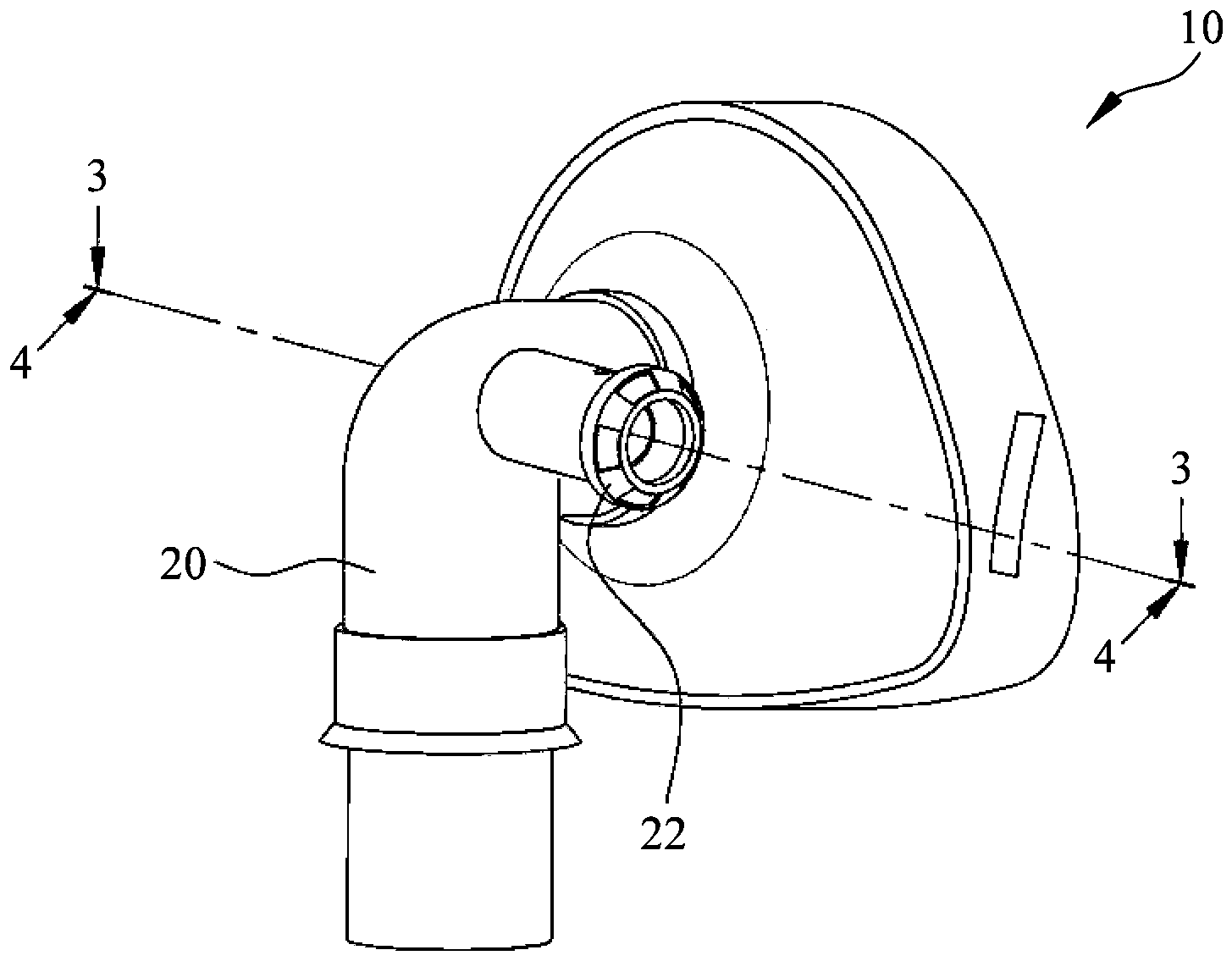
1 das Aussehen und den Aufbau der Beatmungsvorrichtung gemäß einer erfindungsgemäßen Ausführungsform in einer schematischen Ansicht; -
2 den Zustand der Beatmungsvorrichtung gemäß einer erfindungsgemäßen Ausführungsform, wenn sie von einem Benutzer getragen wird, in einer schematischen Ansicht; -
3 die Beatmungsvorrichtung gemäß einem Querschnitt entlang und in Richtung der Linie 3-3 von1 , in einer schematischen Schnittansicht; -
4 die Beatmungsvorrichtung gemäß einem Querschnitt entlang und in Richtung der Linie 4-4 von1 , in einer schematischen Schnittansicht; -
5 die Beatmungsvorrichtung gemäß einem Querschnitt entlang und in Richtung der Linie 4-4 von1 , die den Zustand des Einatmens des Außenluftstroms veranschaulicht, wenn der Luftstrom gemäß einer erfindungsgemäßen Ausführungsform aus dem Düsenrohr geblasen wird, in einer schematischen Schnittansicht; und -
6 eine weitere erfindungsgemäße Ausführungsform des Düsenrohres, in einer schematischen Schnittansicht.
-
1 the appearance and structure of the ventilation device according to an embodiment of the invention in a schematic view; -
2 the state of the ventilation device according to an embodiment of the invention when it is worn by a user, in a schematic view; -
3 the ventilator according to a cross section taken along and in the direction of line 3-3 of FIG1 , in a schematic sectional view; -
4th the ventilator according to a cross section taken along and in the direction of line 4-4 of FIG1 , in a schematic sectional view; -
5 the ventilator according to a cross section taken along and in the direction of line 4-4 of FIG1 which illustrates the state of inhaling the outside air flow when the air flow is blown out of the nozzle pipe according to an embodiment of the present invention, in a schematic sectional view; and -
6 a further embodiment of the nozzle tube according to the invention, in a schematic sectional view.
DETAILLIERTE BESCHREIBUNG DER BEVORZUGTEN AUSFÜHRUNGSFORMDETAILED DESCRIPTION OF THE PREFERRED EMBODIMENT
Die beigefügten Zeichnungen dienen dem weiteren Verständnis der Erfindung und werden von der vorliegenden Beschreibung in Bezug genommen und bilden einen Teil dieser Beschreibung. Die Zeichnungen veranschaulichen beispielhafte Ausführungsformen der Erfindung und dienen zusammen mit der Beschreibung dazu, die Grundsätze der Erfindung zu erläutern.The accompanying drawings serve to further understand the invention and are illustrated by of the present specification and form a part of this specification. The drawings illustrate exemplary embodiments of the invention and, together with the description, serve to explain the principles of the invention.
Die in
Die Maske
Wie in den
Darüber hinaus ist erfindungsgemäß ein Lufteinlassrohr
Im Anwendungsfall wird die erfindungsgemäße Beatmungsvorrichtung in Verbindung mit den am Rand der Maske
Obwohl die vorliegende Erfindung zuvor unter Bezugnahme auf die bevorzugten Ausführungsformen beschrieben wurde, ist es für die Fachmann im Stand der Technik offensichtlich, dass eine Vielzahl von Änderungen und Modifikationen vorgenommen werden können, ohne vom Umfang der vorliegenden Erfindung abzuweichen, der durch die beigefügten Ansprüche definiert werden soll.Although the present invention has been described above with reference to the preferred embodiments, it will be apparent to those skilled in the art that various changes and modifications can be made without departing from the scope of the present invention, which is defined by the appended claims shall be.
Zusammenfassend wird eine Beatmungsvorrichtung mit einem Düsenrohr, das axial in einem Luftauslasskanal einer Maske ausgebildet ist, zur Verfügung gestellt. Das dem Luftauslass-Rückschlagventil des Luftauslasskanals zugewandte Luftauslassende des Düsenrohrs weist einen sich reduzierenden Durchmesser auf. Senkrecht zu der Mittelachse des Luftauslassendes ist zwischen der Seitenwand des Luftauslasskanals und der Seitenwand des Düsenrohres mindestens ein Durchgangsloch vorgesehen, um die Außenseite des Auslasskanals mit der Innenseite des Düsenrohres fluidleitend zu verbinden. Wenn die ausgeatmete Luft durch das Düsenrohr strömt, dann wird die Luft von außen in das Düsenrohr eingesaugt, um den Luftstrom entsprechend dem Bernoulli-Prinzip zu erhöhen, und wenn der Luftstrom aus dem Düsenrohr bläst wird genügend Kraft erzeugt, um das Luftauslass-Rückschlagventil zu öffnen, um das ausgeatmete Kohlendioxid abzuführen.In summary, a ventilation device is provided with a nozzle tube which is formed axially in an air outlet channel of a mask. The air outlet end of the nozzle tube facing the air outlet check valve of the air outlet channel has a reducing diameter. At least one through hole is provided perpendicular to the center axis of the air outlet end between the side wall of the air outlet channel and the side wall of the nozzle tube in order to fluidically connect the outside of the outlet channel to the inside of the nozzle tube. When the exhaled air flows through the nozzle tube, the air is sucked into the nozzle tube from the outside to increase the air flow according to the Bernoulli principle, and when the air flow blows out of the nozzle tube enough force is generated to close the air outlet check valve open to vent the exhaled carbon dioxide.
ZITATE ENTHALTEN IN DER BESCHREIBUNGQUOTES INCLUDED IN THE DESCRIPTION
Diese Liste der vom Anmelder aufgeführten Dokumente wurde automatisiert erzeugt und ist ausschließlich zur besseren Information des Lesers aufgenommen. Die Liste ist nicht Bestandteil der deutschen Patent- bzw. Gebrauchsmusteranmeldung. Das DPMA übernimmt keinerlei Haftung für etwaige Fehler oder Auslassungen.This list of the documents listed by the applicant was generated automatically and is included solely for the better information of the reader. The list is not part of the German patent or utility model application. The DPMA assumes no liability for any errors or omissions.
Zitierte PatentliteraturPatent literature cited
- TW 109131533 [0001]TW 109131533 [0001]
Claims (5)
Applications Claiming Priority (2)
| Application Number | Priority Date | Filing Date | Title |
|---|---|---|---|
| TW109131533 | 2020-09-14 | ||
| TW109131533A TWI738506B (en) | 2020-09-14 | 2020-09-14 | Respiratory assist device |
Publications (1)
| Publication Number | Publication Date |
|---|---|
| DE202020106605U1 true DE202020106605U1 (en) | 2020-12-21 |
Family
ID=74099117
Family Applications (1)
| Application Number | Title | Priority Date | Filing Date |
|---|---|---|---|
| DE202020106605.6U Expired - Lifetime DE202020106605U1 (en) | 2020-09-14 | 2020-11-18 | Ventilation device |
Country Status (3)
| Country | Link |
|---|---|
| US (1) | US20220080146A1 (en) |
| DE (1) | DE202020106605U1 (en) |
| TW (1) | TWI738506B (en) |
Families Citing this family (4)
| Publication number | Priority date | Publication date | Assignee | Title |
|---|---|---|---|---|
| US12172040B2 (en) * | 2020-09-15 | 2024-12-24 | Emad Eskandar | Wearable, maskless respiratory isolation device |
| CN116236662A (en) * | 2022-12-22 | 2023-06-09 | 北京谊安健康科技有限公司 | Gas lines and ventilators for ventilator hosts |
| CN116999666A (en) * | 2023-08-31 | 2023-11-07 | 中科帅博健康科技有限公司 | A helmet-type hydrogen absorption device |
| WO2025079004A1 (en) * | 2023-10-13 | 2025-04-17 | Fisher & Paykel Healthcare Limited | Oral interface for providing respiratory support |
Family Cites Families (10)
| Publication number | Priority date | Publication date | Assignee | Title |
|---|---|---|---|---|
| US6578571B1 (en) * | 1998-04-20 | 2003-06-17 | Infamed Ltd. | Drug delivery device and methods therefor |
| AU2003219625A1 (en) * | 2002-02-04 | 2003-09-02 | Fisher And Paykel Healthcare Limited | Breathing assistance apparatus |
| ITFI20030199A1 (en) * | 2003-07-25 | 2005-01-26 | Cressi Sub Spa | SECONDARY VALVE PERFECTED FOR BRUSHING. |
| US20100199991A1 (en) * | 2009-02-06 | 2010-08-12 | Hartwell Medical Corporation | Ventilatory support and resuscitation device and associated method |
| US8567400B2 (en) * | 2010-10-05 | 2013-10-29 | Carefusion 207, Inc. | Non-invasive breathing assistance device with flow director |
| CA2863077A1 (en) * | 2012-01-23 | 2013-08-01 | Aeon Research And Tecnology, Llc | Modular pulmonary treatment system |
| TWI562803B (en) * | 2014-09-15 | 2016-12-21 | Delta Electronics Inc | Gas exhaust control method and respiratory assistance apparatus applied the same |
| US10953278B2 (en) * | 2018-02-02 | 2021-03-23 | Trudell Medical International | Oscillating positive expiratory pressure device |
| TWM580979U (en) * | 2019-01-16 | 2019-07-21 | 遠貿企業股份有限公司 | Tracheostomy mask |
| TWM605814U (en) * | 2020-09-14 | 2020-12-21 | 南緯實業股份有限公司 | Auxiliary device for breathing |
-
2020
- 2020-09-14 TW TW109131533A patent/TWI738506B/en not_active IP Right Cessation
- 2020-10-27 US US16/949,364 patent/US20220080146A1/en not_active Abandoned
- 2020-11-18 DE DE202020106605.6U patent/DE202020106605U1/en not_active Expired - Lifetime
Also Published As
| Publication number | Publication date |
|---|---|
| TWI738506B (en) | 2021-09-01 |
| TW202210122A (en) | 2022-03-16 |
| US20220080146A1 (en) | 2022-03-17 |
Similar Documents
| Publication | Publication Date | Title |
|---|---|---|
| DE202020106605U1 (en) | Ventilation device | |
| EP2259829B1 (en) | Applicators for a nasal cannula | |
| DE60226101T2 (en) | Exhalation valve for a nasal respiratory mask | |
| DE69618133T2 (en) | Tracheal tube and device for ventilation systems | |
| DE69425613T2 (en) | Respiratory mask for the face | |
| DE10105383C2 (en) | Anti-snoring device | |
| DE69911704T2 (en) | Respiratory support device | |
| EP1654023B1 (en) | Arrangement for respiratory support for a patient | |
| DE19817332C2 (en) | oxygen mask | |
| DE69512985T2 (en) | Respiratory support device | |
| DE102009003605B4 (en) | System for integrated high-frequency oscillatory ventilation | |
| DE69820275T2 (en) | SPONTANEOUS BREATHING APPARATUS | |
| DE60318980T2 (en) | Device for breathing gas supply | |
| DE2453490A1 (en) | PIPING SYSTEM OF A BREATHING DEVICE | |
| DE3435565A1 (en) | METHOD AND DEVICE FOR TREATING AN OBTURING SLEEP BREATH | |
| DE212011100071U1 (en) | Tracheal couplings and associated systems | |
| DE112009000400T5 (en) | Device for providing continuous positive air pressure | |
| EP3536369B1 (en) | Respiratory apparatus with switching valve | |
| DE10046872B4 (en) | Breathing assistance apparatus | |
| DE10331837B3 (en) | Face mask for breathing gear has cover fitting over part of face and nose of user, connected to air hose at top with fastening device engaging patient's forehead and flexible bellows | |
| DE102005018696A1 (en) | Arrangement of respiratory tubes to be attached to nostrils, comprising tubes for being fastened to chin | |
| EP3615120A1 (en) | Patient valve for ventilating a patient with a ventilator | |
| DE102022004180A1 (en) | System to support pulmonary gas exchange in patients | |
| DE102005039502B4 (en) | Mouthpiece for a medicine inhaler | |
| DE19825290A1 (en) | Respiratory device for the treatment of sleep apnea |
Legal Events
| Date | Code | Title | Description |
|---|---|---|---|
| R207 | Utility model specification | ||
| R082 | Change of representative | ||
| R156 | Lapse of ip right after 3 years |