DE202018006714U1 - Power converter unit, plasma processing device and control device for controlling multiple plasma processes - Google Patents
Power converter unit, plasma processing device and control device for controlling multiple plasma processes Download PDFInfo
- Publication number
- DE202018006714U1 DE202018006714U1 DE202018006714.8U DE202018006714U DE202018006714U1 DE 202018006714 U1 DE202018006714 U1 DE 202018006714U1 DE 202018006714 U DE202018006714 U DE 202018006714U DE 202018006714 U1 DE202018006714 U1 DE 202018006714U1
- Authority
- DE
- Germany
- Prior art keywords
- power
- power converter
- converter unit
- output
- plasma processing
- Prior art date
- Legal status (The legal status is an assumption and is not a legal conclusion. Google has not performed a legal analysis and makes no representation as to the accuracy of the status listed.)
- Active
Links
- 238000000034 method Methods 0.000 title claims abstract description 30
- 230000005284 excitation Effects 0.000 claims abstract description 12
- 230000001681 protective effect Effects 0.000 claims abstract description 7
- 238000004364 calculation method Methods 0.000 claims description 6
- 238000000623 plasma-assisted chemical vapour deposition Methods 0.000 claims description 5
- 108010076504 Protein Sorting Signals Proteins 0.000 description 8
- 238000010586 diagram Methods 0.000 description 8
- 239000003990 capacitor Substances 0.000 description 3
- 238000000231 atomic layer deposition Methods 0.000 description 2
- 230000015556 catabolic process Effects 0.000 description 2
- 238000004146 energy storage Methods 0.000 description 2
- 238000005240 physical vapour deposition Methods 0.000 description 2
- BUHVIAUBTBOHAG-FOYDDCNASA-N (2r,3r,4s,5r)-2-[6-[[2-(3,5-dimethoxyphenyl)-2-(2-methylphenyl)ethyl]amino]purin-9-yl]-5-(hydroxymethyl)oxolane-3,4-diol Chemical compound COC1=CC(OC)=CC(C(CNC=2C=3N=CN(C=3N=CN=2)[C@H]2[C@@H]([C@H](O)[C@@H](CO)O2)O)C=2C(=CC=CC=2)C)=C1 BUHVIAUBTBOHAG-FOYDDCNASA-N 0.000 description 1
- 238000004140 cleaning Methods 0.000 description 1
- 238000001816 cooling Methods 0.000 description 1
- 230000001419 dependent effect Effects 0.000 description 1
- 238000005530 etching Methods 0.000 description 1
- ZINJLDJMHCUBIP-UHFFFAOYSA-N ethametsulfuron-methyl Chemical compound CCOC1=NC(NC)=NC(NC(=O)NS(=O)(=O)C=2C(=CC=CC=2)C(=O)OC)=N1 ZINJLDJMHCUBIP-UHFFFAOYSA-N 0.000 description 1
- 238000009434 installation Methods 0.000 description 1
- 239000002184 metal Substances 0.000 description 1
- 238000001020 plasma etching Methods 0.000 description 1
- 238000004886 process control Methods 0.000 description 1
Images


Classifications
-
- H—ELECTRICITY
- H01—ELECTRIC ELEMENTS
- H01J—ELECTRIC DISCHARGE TUBES OR DISCHARGE LAMPS
- H01J37/00—Discharge tubes with provision for introducing objects or material to be exposed to the discharge, e.g. for the purpose of examination or processing thereof
- H01J37/32—Gas-filled discharge tubes
- H01J37/32431—Constructional details of the reactor
- H01J37/32798—Further details of plasma apparatus not provided for in groups H01J37/3244 - H01J37/32788; special provisions for cleaning or maintenance of the apparatus
- H01J37/32899—Multiple chambers, e.g. cluster tools
-
- C—CHEMISTRY; METALLURGY
- C23—COATING METALLIC MATERIAL; COATING MATERIAL WITH METALLIC MATERIAL; CHEMICAL SURFACE TREATMENT; DIFFUSION TREATMENT OF METALLIC MATERIAL; COATING BY VACUUM EVAPORATION, BY SPUTTERING, BY ION IMPLANTATION OR BY CHEMICAL VAPOUR DEPOSITION, IN GENERAL; INHIBITING CORROSION OF METALLIC MATERIAL OR INCRUSTATION IN GENERAL
- C23C—COATING METALLIC MATERIAL; COATING MATERIAL WITH METALLIC MATERIAL; SURFACE TREATMENT OF METALLIC MATERIAL BY DIFFUSION INTO THE SURFACE, BY CHEMICAL CONVERSION OR SUBSTITUTION; COATING BY VACUUM EVAPORATION, BY SPUTTERING, BY ION IMPLANTATION OR BY CHEMICAL VAPOUR DEPOSITION, IN GENERAL
- C23C14/00—Coating by vacuum evaporation, by sputtering or by ion implantation of the coating forming material
- C23C14/22—Coating by vacuum evaporation, by sputtering or by ion implantation of the coating forming material characterised by the process of coating
- C23C14/34—Sputtering
-
- C—CHEMISTRY; METALLURGY
- C23—COATING METALLIC MATERIAL; COATING MATERIAL WITH METALLIC MATERIAL; CHEMICAL SURFACE TREATMENT; DIFFUSION TREATMENT OF METALLIC MATERIAL; COATING BY VACUUM EVAPORATION, BY SPUTTERING, BY ION IMPLANTATION OR BY CHEMICAL VAPOUR DEPOSITION, IN GENERAL; INHIBITING CORROSION OF METALLIC MATERIAL OR INCRUSTATION IN GENERAL
- C23C—COATING METALLIC MATERIAL; COATING MATERIAL WITH METALLIC MATERIAL; SURFACE TREATMENT OF METALLIC MATERIAL BY DIFFUSION INTO THE SURFACE, BY CHEMICAL CONVERSION OR SUBSTITUTION; COATING BY VACUUM EVAPORATION, BY SPUTTERING, BY ION IMPLANTATION OR BY CHEMICAL VAPOUR DEPOSITION, IN GENERAL
- C23C16/00—Chemical coating by decomposition of gaseous compounds, without leaving reaction products of surface material in the coating, i.e. chemical vapour deposition [CVD] processes
- C23C16/44—Chemical coating by decomposition of gaseous compounds, without leaving reaction products of surface material in the coating, i.e. chemical vapour deposition [CVD] processes characterised by the method of coating
- C23C16/50—Chemical coating by decomposition of gaseous compounds, without leaving reaction products of surface material in the coating, i.e. chemical vapour deposition [CVD] processes characterised by the method of coating using electric discharges
-
- H—ELECTRICITY
- H01—ELECTRIC ELEMENTS
- H01J—ELECTRIC DISCHARGE TUBES OR DISCHARGE LAMPS
- H01J37/00—Discharge tubes with provision for introducing objects or material to be exposed to the discharge, e.g. for the purpose of examination or processing thereof
- H01J37/32—Gas-filled discharge tubes
- H01J37/32009—Arrangements for generation of plasma specially adapted for examination or treatment of objects, e.g. plasma sources
- H01J37/32018—Glow discharge
- H01J37/32027—DC powered
-
- H—ELECTRICITY
- H01—ELECTRIC ELEMENTS
- H01J—ELECTRIC DISCHARGE TUBES OR DISCHARGE LAMPS
- H01J37/00—Discharge tubes with provision for introducing objects or material to be exposed to the discharge, e.g. for the purpose of examination or processing thereof
- H01J37/32—Gas-filled discharge tubes
- H01J37/32009—Arrangements for generation of plasma specially adapted for examination or treatment of objects, e.g. plasma sources
- H01J37/32018—Glow discharge
- H01J37/32036—AC powered
-
- H—ELECTRICITY
- H01—ELECTRIC ELEMENTS
- H01J—ELECTRIC DISCHARGE TUBES OR DISCHARGE LAMPS
- H01J37/00—Discharge tubes with provision for introducing objects or material to be exposed to the discharge, e.g. for the purpose of examination or processing thereof
- H01J37/32—Gas-filled discharge tubes
- H01J37/32431—Constructional details of the reactor
- H01J37/32798—Further details of plasma apparatus not provided for in groups H01J37/3244 - H01J37/32788; special provisions for cleaning or maintenance of the apparatus
- H01J37/32889—Connection or combination with other apparatus
-
- H—ELECTRICITY
- H01—ELECTRIC ELEMENTS
- H01J—ELECTRIC DISCHARGE TUBES OR DISCHARGE LAMPS
- H01J37/00—Discharge tubes with provision for introducing objects or material to be exposed to the discharge, e.g. for the purpose of examination or processing thereof
- H01J37/32—Gas-filled discharge tubes
- H01J37/32431—Constructional details of the reactor
- H01J37/32798—Further details of plasma apparatus not provided for in groups H01J37/3244 - H01J37/32788; special provisions for cleaning or maintenance of the apparatus
- H01J37/32908—Utilities
-
- H—ELECTRICITY
- H01—ELECTRIC ELEMENTS
- H01J—ELECTRIC DISCHARGE TUBES OR DISCHARGE LAMPS
- H01J37/00—Discharge tubes with provision for introducing objects or material to be exposed to the discharge, e.g. for the purpose of examination or processing thereof
- H01J37/32—Gas-filled discharge tubes
- H01J37/34—Gas-filled discharge tubes operating with cathodic sputtering
-
- H—ELECTRICITY
- H02—GENERATION; CONVERSION OR DISTRIBUTION OF ELECTRIC POWER
- H02M—APPARATUS FOR CONVERSION BETWEEN AC AND AC, BETWEEN AC AND DC, OR BETWEEN DC AND DC, AND FOR USE WITH MAINS OR SIMILAR POWER SUPPLY SYSTEMS; CONVERSION OF DC OR AC INPUT POWER INTO SURGE OUTPUT POWER; CONTROL OR REGULATION THEREOF
- H02M5/00—Conversion of AC power input into AC power output, e.g. for change of voltage, for change of frequency, for change of number of phases
- H02M5/40—Conversion of AC power input into AC power output, e.g. for change of voltage, for change of frequency, for change of number of phases with intermediate conversion into DC
- H02M5/42—Conversion of AC power input into AC power output, e.g. for change of voltage, for change of frequency, for change of number of phases with intermediate conversion into DC by static converters
- H02M5/44—Conversion of AC power input into AC power output, e.g. for change of voltage, for change of frequency, for change of number of phases with intermediate conversion into DC by static converters using discharge tubes or semiconductor devices to convert the intermediate DC into AC
- H02M5/453—Conversion of AC power input into AC power output, e.g. for change of voltage, for change of frequency, for change of number of phases with intermediate conversion into DC by static converters using discharge tubes or semiconductor devices to convert the intermediate DC into AC using devices of a triode or transistor type requiring continuous application of a control signal
- H02M5/458—Conversion of AC power input into AC power output, e.g. for change of voltage, for change of frequency, for change of number of phases with intermediate conversion into DC by static converters using discharge tubes or semiconductor devices to convert the intermediate DC into AC using devices of a triode or transistor type requiring continuous application of a control signal using semiconductor devices only
-
- H—ELECTRICITY
- H01—ELECTRIC ELEMENTS
- H01J—ELECTRIC DISCHARGE TUBES OR DISCHARGE LAMPS
- H01J37/00—Discharge tubes with provision for introducing objects or material to be exposed to the discharge, e.g. for the purpose of examination or processing thereof
- H01J37/32—Gas-filled discharge tubes
- H01J37/32917—Plasma diagnostics
- H01J37/32926—Software, data control or modelling
-
- H—ELECTRICITY
- H02—GENERATION; CONVERSION OR DISTRIBUTION OF ELECTRIC POWER
- H02M—APPARATUS FOR CONVERSION BETWEEN AC AND AC, BETWEEN AC AND DC, OR BETWEEN DC AND DC, AND FOR USE WITH MAINS OR SIMILAR POWER SUPPLY SYSTEMS; CONVERSION OF DC OR AC INPUT POWER INTO SURGE OUTPUT POWER; CONTROL OR REGULATION THEREOF
- H02M1/00—Details of apparatus for conversion
- H02M1/0067—Converter structures employing plural converter units, other than for parallel operation of the units on a single load
- H02M1/008—Plural converter units for generating at two or more independent and non-parallel outputs, e.g. systems with plural point of load switching regulators
-
- H—ELECTRICITY
- H02—GENERATION; CONVERSION OR DISTRIBUTION OF ELECTRIC POWER
- H02M—APPARATUS FOR CONVERSION BETWEEN AC AND AC, BETWEEN AC AND DC, OR BETWEEN DC AND DC, AND FOR USE WITH MAINS OR SIMILAR POWER SUPPLY SYSTEMS; CONVERSION OF DC OR AC INPUT POWER INTO SURGE OUTPUT POWER; CONTROL OR REGULATION THEREOF
- H02M1/00—Details of apparatus for conversion
- H02M1/0083—Converters characterised by their input or output configuration
- H02M1/009—Converters characterised by their input or output configuration having two or more independently controlled outputs
Landscapes
- Chemical & Material Sciences (AREA)
- Engineering & Computer Science (AREA)
- Physics & Mathematics (AREA)
- Plasma & Fusion (AREA)
- Analytical Chemistry (AREA)
- Power Engineering (AREA)
- Mechanical Engineering (AREA)
- Chemical Kinetics & Catalysis (AREA)
- Materials Engineering (AREA)
- Metallurgy (AREA)
- Organic Chemistry (AREA)
- General Chemical & Material Sciences (AREA)
- Plasma Technology (AREA)
- Drying Of Semiconductors (AREA)
Abstract
Leistungswandlereinheit (1, 1'), die in der Lage ist, eine elektrische Eingangsleistung in eine bipolare Ausgangsleistung umzuwandeln und diese Ausgangsleistung an mindestens zwei unabhängige Plasmabearbeitungskammern (9a, 9b, ... 9n) zu liefern, wobei die Leistungswandlereinheit (1, 1') umfasst:
- einen Leistungseingangsanschluss (2) zum Anschluss an ein elektrisches Stromversorgungsnetz (7),
- mindestens zwei, vorzugsweise mehr als zwei, Leistungsausgangsanschlüsse (3a, 3b, .. 3n) jeweils zum Anschluss an eine der Plasmabearbeitungskammern (9a, 9b, ... 9n)
- eine Steuereinrichtung (4), die so konfiguriert ist, dass sie die Leistungswandlereinheit (1, 1') steuert, um die bipolare Ausgangsleistung an die Leistungsausgangsanschlüsse (3a, 3b, ... 3n) zu liefern, unter Verwendung von mindestens einem der folgenden Steuerparameter:
Leistung, Spannung, Strom, Anregungsfrequenz oder Schwellenwert für Schutzmaßnahmen durch Erhalten einer vollständigen Menge Sollwerte für die Parameter der Ausgangsanschlüsse (3a, 3b, ... 3n), wobei die Steuereinrichtung (4) ferner dazu ausgelegt ist zu berechnen, ob die Leistungswandlereinheit (1, 1') in der Lage ist, jeden Sollwert zu jedem Ausgangsanschluss (3a, 3b, ... 3n) zu liefern und, wenn das zutreffend ist, eine Sequenz von Pulsen für die Leistungslieferung zu den Leistungsausgangsanschlüssen (3a, 3b, ... 3n) zu errechnen, um die Leistung für den Plasmaprozess bereitzustellen.
- a power input connection (2) for connection to an electrical power supply network (7),
- at least two, preferably more than two, power output terminals (3a, 3b, .. 3n) each for connection to one of the plasma processing chambers (9a, 9b, ... 9n)
- a controller (4) configured to control the power converter unit (1, 1') to deliver the bipolar output power to the power output terminals (3a, 3b, ... 3n) using at least one of the following control parameters:
Power, voltage, current, excitation frequency or threshold for protective measures by obtaining a complete set of target values for the parameters of the output terminals (3a, 3b, ... 3n), the control means (4) being further adapted to calculate whether the power converter unit ( 1, 1') is capable of delivering any setpoint to any output port (3a, 3b, ... 3n) and, when applicable, a sequence of pulses for power delivery to the power output ports (3a, 3b, . .. 3n) to provide the power for the plasma process.
Description
Die Erfindung betrifft eine Leistungswandlereinheit und eine Plasmabearbeitungseinrichtung und eine Steuereinrichtung zur Steuerung mehrerer Plasmaprozesse.
Viele Plasmabearbeitungseinrichtungen verwenden mehrere unabhängige Plasmakammern, in denen Plasmabearbeitung parallel durchgeführt wird. Solche Plasmabearbeitungseinrichtungen sind bekannt aus
Many plasma processing facilities use multiple independent plasma chambers in which plasma processing is performed in parallel. Such plasma processing devices are known from
Es ist eine Aufgabe der vorliegenden Erfindung, die überschüssigen Kosten zu reduzieren.It is an object of the present invention to reduce the excess cost.
Die Aufgabe wird gelöst durch eine Leistungswandlereinheit nach Anspruch 1 und durch eine Plasmabearbeitungseinrichtung nach Anspruch 6 sowie durch eine Steuereinrichtung nach Anspruch 8. Weitere bevorzugte Aspekte der Erfindung sind in den abhängigen Ansprüchen und der Beschreibung behandelt.The object is solved by a power converter unit according to
Die Leistungswandlereinheit ist in der Lage, eine elektrische Eingangsleistung in eine bipolare Ausgangsleistung umzuwandeln und diese Ausgangsleistung an mindestens zwei unabhängige Plasmabearbeitungskammern zu liefern, wobei die Leistungswandlereinheit Folgendes umfasst:
- - einen Leistungseingangsanschluss zum Anschluss an ein elektrisches Stromversorgungsnetz,
- - mindestens zwei, vorzugsweise mehr als zwei, Leistungsausgangsanschlüsse, jeweils zum Anschluss an eine der Plasmabearbeitungskammern
- - eine Steuereinrichtung, die so konfiguriert ist, dass sie die Leistungswandlereinheit steuert, um die bipolare Ausgangsleistung an die Leistungsausgangsanschlüsse zu liefern, unter Verwendung von mindestens einem der folgenden Steuerparamatern:
- Leistung, Spannung, Strom, Anregungsfrequenz oder Schwellenwert für Schutzmaßnahmen durch Erhalten einer vollständigen Menge Sollwerte für die Parameter der Ausgangsanschlüsse,
- - a power input connector for connection to an electrical power supply network,
- - at least two, preferably more than two, power output terminals, each for connection to one of the plasma processing chambers
- - a controller configured to control the power converter unit to deliver the bipolar output power to the power output terminals using at least one of the following control parameters:
- Power, voltage, current, excitation frequency or threshold for protection measures by obtaining a complete set of setpoints for output port parameters,
In einem weiteren Aspekt kann die Steuereinrichtung konfiguriert sein, um die Leistungswandlereinheit zu steuern, sodass mindestens einer der Steuerparameter an einem ersten Leistungsausgangsanschluss ungleich dem entsprechenden Steuerparameter eines anderen Leistungsausgangsanschlusses ist. Dadurch kann eine einzelne Leistungswandlereinheit mit gegebener Maximalleistung anstatt mehrerer verwendet werden.In another aspect, the controller may be configured to control the power converter unit such that at least one of the control parameters at a first power output port is unequal to the corresponding control parameter at another power output port. This allows a single power converter unit with a given maximum power to be used instead of several.
Mit bipolarer Ausgangsleistung ist in dieser Offenlegung eine Ausgangsleistung mit einem Wechselstrom gemeint, bei dem der Strom seine Richtung mit einer Frequenz ändert, die den Plasmaprozess anregen kann (Anregungsfrequenz).By bipolar output power in this disclosure is meant an output power with an alternating current in which the current changes direction with a frequency that can excite the plasma process (excitation frequency).
Regelparameter können Messwerte oder Sollwerte der genannten Parameter sein.Control parameters can be measured values or setpoint values of the parameters mentioned.
Die Mess- und Sollwerte können Absolutwert, Momentanwert, Effektivwert, wie z.B. ein RMS (root mean square)-Wert, oder Extremwert (z. B. Maximal- oder Minimalwert) sein.The measured and set values can be absolute values, instantaneous values, effective values such as an RMS (root mean square) value, or extreme values (e.g. maximum or minimum value).
Die Eingangsleistung kann eine elektrische Leistung sein, die aus einem AC-Netz geliefert wird. Es kann auch eine DC-Leistungsleitung sein (AC: Wechselstrom; DC: Gleichstrom).The input power can be electrical power supplied from an AC grid. It can also be a DC power line (AC: alternating current; DC: direct current).
Die Steuereinrichtung kann aus einem Mikrocontroller bestehen, auf dem ein Softwareprogramm läuft, wenn die Leistungswandlereinheit in Betrieb ist.The controller may consist of a microcontroller running a software program when the power converter unit is in operation.
Die Steuereinrichtung kann mehrere Schnittstellen haben, wie z. B. Datenverbindungen zu externen Komponenten, Monitoren, Tastaturen, die drahtgebunden oder drahtlos angeschlossen werden können.The control device can have several interfaces, such as e.g. B. Data connections to external components, monitors, keyboards that can be wired or wirelessly connected.
Die Steuereinrichtung kann einen Rechenteil und einen Speicherteil haben. Der Speicherteil kann für verschiedene Zwecke unterteilt sein, z. B. als Monitorspeicher, RAM, Datenspeicher, Programmspeicher.The controller may have an arithmetic part and a storage part. The memory part can be divided for different purposes, e.g. B. as monitor memory, RAM, data memory, program memory.
Ein Schwellenwert kann ein Wert sein, der zur Erkennung der Zündung oder des Zusammenbruchs des Plasmas verwendet wird. Er kann für jeden Ausgangsport unterschiedlich festgelegt werden und sich über die Zeit ändern.A threshold may be a value used to detect ignition or collapse of the plasma. It can be set differently for each output port and can change over time.
Die bipolare Ausgangsleistung kann ein Leistungswert von mehr als 1 kW, vorzugsweise mehr als 10 kW sein.The bipolar output power can be a power value of more than 1 kW, preferably more than 10 kW.
Die bipolare Ausgangsleistung kann eine Frequenz von mehr als 1 kHz, vorzugsweise mehr als 10 kHz, vorzugsweise mehr als 50 kHz, aufweisen.The bipolar output power can have a frequency of more than 1 kHz, preferably more than 10 kHz, preferably more than 50 kHz.
In einem weiteren Aspekt kann die Leistungswandlereinheit eine erste Leistungswandlerstufe umfassen, die dazu ausgebildet ist, dass sie die Eingangsleistung in eine Zwischenleistung, vorzugsweise in eine DC-Zwischenkreisleistung, umwandelt.In a further aspect, the power converter unit may comprise a first power converter stage configured to convert the input power into an intermediate power, preferably into a DC link power.
In einem weiteren Aspekt kann die Leistungswandlereinheit mindestens eine weitere Leistungswandlerstufe umfassen, die dazu ausgebildet ist, die Zwischenleistung von der ersten Leistungswandlerstufe in die bipolare Ausgangsleistung umzuwandeln.In a further aspect, the power converter unit may comprise at least one further power converter stage configured to convert the intermediate power from the first power converter stage into the bipolar output power.
In einem weiteren Aspekt kann die Leistungswandlereinheit mindestens zwei weitere Leistungswandlerstufen umfassen, die dazu ausgebildet sind, die Zwischenleistung von der ersten Leistungswandlerstufe in mehrere bipolare Ausgangsleistungssignale umzuwandeln und diese Leistungen zu den Leistungsausgangsanschlüssen zu führen.In another aspect, the power converter unit may include at least two further power converter stages configured to convert the intermediate power from the first power converter stage into a plurality of bipolar output power signals and to route these powers to the power output terminals.
In einem weiteren Aspekt kann die Steuereinrichtung dazu ausgebildet sein, die Leistungswandlerstufen so zu steuern, dass, während der Benutzung, die Leistungswandlereinheit zu einem ersten Zeitpunkt ein erstes Ausgangsleistungssignal an einem ersten Leistungsausgangsanschluss für einen ersten Zeitrahmen und zu einem zweiten Zeitpunkt ein zweites Ausgangsleistungssignal an einem zweiten Leistungsausgangsanschluss für einen zweiten Zeitrahmen liefert, wobei der erste Zeitpunkt anders ist als der zweite Zeitpunkt und/oder der erste Zeitrahmen anders als der zweite Zeitrahmen.In another aspect, the controller may be configured to control the power converter stages such that, during use, the power converter unit outputs a first power output signal at a first power output port for a first time frame at a first time and a second power output signal at a second time second power output port for a second time frame, wherein the first time is different than the second time and/or the first time frame is different than the second time frame.
In einem weiteren Aspekt kann die Leistungswandlereinheit Schaltmittel zwischen der/den Leistungswandlerstufe(n) und den Leistungsausgangsanschlüssen umfassen.In a further aspect, the power converter unit may comprise switching means between the power converter stage(s) and the power output terminals.
In einem weiteren Aspekt werden die Schaltmittel von der Steuereinrichtung gesteuert. Schaltmittel zum Schalten zwischen Elektroden in nur einer Plasmabearbeitungskammer sind in
In einem weiteren Aspekt kann die Steuereinrichtung so ausgebildet sein, die Leistungswandlerstufen und/oder die Schaltmittel derart zu steuern, dass die Leistungswandlereinheit im Betrieb zu einem ersten Zeitpunkt ein erstes Ausgangsleistungssignal an dem ersten Leistungsausgangsanschluss für einen ersten Zeitrahmen und zu einem zweiten Zeitpunkt ein zweites Ausgangsleistungssignal an dem zweiten Leistungsausgangsanschluss für einen zweiten Zeitrahmen liefert, wobei der erste Zeitpunkt von dem zweiten Zeitpunkt verschieden ist und/oder der erste Zeitrahmen von dem zweiten Zeitrahmen verschieden ist.In a further aspect, the control device can be designed to control the power converter stages and/or the switching means in such a way that the power converter unit produces a first output power signal at the first power output terminal for a first time frame at a first point in time and a second output power signal at a second point in time at the second power output port for a second time frame, wherein the first time differs from the second time and/or the first time frame differs from the second time frame.
In einem weiteren Aspekt sind die Schaltmittel so ausgestaltet, dass sie Strom in zwei entgegengesetzte Richtungen leiten können.In a further aspect, the switching means are designed in such a way that they can conduct current in two opposite directions.
In einem weiteren Aspekt kann die Steuereinrichtung so konfiguriert sein, dass sie ein Schaltmittel nur dann von einem geschlossenen Zustand in einen offenen Zustand umschaltet, wenn der Betrag des Stroms durch den Schalter kleiner als ein Ampere, vorzugsweise null, ist.In a further aspect, the controller may be configured to switch a switching means from a closed state to an open state only when the magnitude of the current through the switch is less than one ampere, preferably zero.
In einem weiteren Aspekt kann die Steuereinrichtung so konfiguriert sein, dass sie ein Schaltmittel von einem offenen Zustand in einen geschlossenen Zustand nur dann aktiviert, wenn der Betrag der Spannung entlang des offenen Schalters niedriger als 20 Volt, vorzugsweise null, ist.In a further aspect, the controller may be configured to activate a switching means from an open state to a closed state only when the magnitude of the voltage across the open switch is less than 20 volts, preferably zero.
In einem weiteren Aspekt umfasst mindestens eine der Leistungswandlerstufen eine Brückenschaltung, vorzugsweise eine Vollbrückenschaltung.In a further aspect, at least one of the power converter stages comprises a bridge circuit, preferably a full bridge circuit.
Eine Brückenschaltung kann eine Gleichrichter-Brückenschaltung sein, die in der Lage ist, eine Wechselstromleistung gleichzurichten.A bridge circuit may be a rectifier bridge circuit capable of rectifying AC power.
Eine Brückenschaltung kann eine bipolare Ausgangsleistung erzeugende Schaltbrückenschaltung sein.A bridge circuit can be a switching bridge circuit generating a bipolar output power.
In einem weiteren Aspekt kann die Leistungswandlereinheit ein Gehäuse umfassen, das alle anderen Teile der Einheit umschließt.In another aspect, the power converter package may include a housing that encloses all other parts of the package.
In einem weiteren Aspekt können die Eingangsanschlüsse direkt mit dem Schaltschrank verbunden sein.In another aspect, the input ports may be connected directly to the control cabinet.
In einem weiteren Aspekt können die Ausgangsanschlüsse direkt mit dem Gehäuse verbunden sein.In another aspect, the output ports may be connected directly to the housing.
In einem weiteren Aspekt kann eine Plasmabearbeitungseinrichtung umfassen:
- - zwei, vorzugsweise mehr als zwei, Plasmabearbeitungskammern,
- - eine elektrische Leistungswandlereinheit wie oben beschrieben.
- - two, preferably more than two, plasma processing chambers,
- - an electric power converter unit as described above.
Jede Plasmabearbeitungskammer kann mit einem der Leistungsausgangsanschlüsse der Leistungswandlereinheit verbunden sein.Each plasma processing chamber can be connected to one of the power output terminals of the power converter unit.
In einem weiteren Aspekt kann mindestens eine der Plasmabearbeitungskammern, vorzugsweise alle Plasmabearbeitungskammern, so konfiguriert sein, dass sie im Betrieb eine Physikalische Gasphasenabscheidung (physical vapor deposition, PVD) durchführt.In another aspect, at least one of the plasma processing chambers, preferably all of the plasma processing chambers, may be configured to perform physical vapor deposition (PVD) during operation.
Mindestens eine der Plasmabearbeitungskammern, vorzugsweise alle Plasmabearbeitungskammern, kann so konfiguriert sein, dass sie im Betrieb einen plasmaunterstützten chemischen Gasphasenabscheidungsprozess (plasma-enhanced chemical vapor deposition, PECVD) durchführt.At least one of the plasma processing chambers, preferably all of the plasma processing chambers, may be configured to operate in a plasma-enhanced chemical vapor deposition (PECVD) process.
Mindestens eine der Plasmabearbeitungskammern, vorzugsweise alle Plasmabearbeitungskammern, kann so konfiguriert sein, dass sie im Betrieb einen Atomlagenabscheidungsprozess (atomic layer deposition, ALD) durchführt.At least one of the plasma processing chambers, preferably all of the plasma processing chambers, may be configured to operatively perform an atomic layer deposition (ALD) process.
Mindestens eine der Plasmabearbeitungskammern, vorzugsweise alle Plasmabearbeitungskammern, kann so konfiguriert sein, dass sie im Betrieb einen Plasmaätzprozess durchführt.At least one of the plasma processing chambers, preferably all of the plasma processing chambers, may be configured to perform a plasma etching process during operation.
Die Aufgabe der Erfindung wird auch gelöst durch eine Steuereinrichtung zur Steuerung mehrerer Plasmaprozesse in mehreren Plasmabearbeitungskammern durch Umwandlung einer elektrischen Eingangsleistung in eine bipolare Ausgangsleistung und Abgabe dieser Ausgangsleistung an die Plasmabearbeitungskammern, wobei die Steuereinrichtung ausgelegt ist, eine Leistungswandlereinheit zur Abgabe der bipolaren Ausgangsleistung an die Leistungsausgänge zu steuern, unter Verwendung von mindestens einem der folgenden Steuerparametern:
- Leistung, Spannung, Strom, Anregungsfrequenz oder Schwellenwert für Schutzmaßnahmen durch Erhalten einer vollständigen Menge Sollwerte für die Parameter der Ausgangsanschlüsse, wobei die Steuereinrichtung ferner dazu ausgelegt ist zu berechnen, ob die Leistungswandlereinheit in der Lage ist, jeden Sollwert zu jedem Ausgangsanschluss zu liefern und, wenn das zutreffend ist, eine Sequenz von Pulsen für die Leistungslieferung zu den Leistungsausgangsanschlüssen zu errechnen, um die Leistung für den Plasmaprozess bereitzustellen.
- Power, voltage, current, excitation frequency or threshold for protective measures by obtaining a complete set of target values for the parameters of the output ports, the controller being further adapted to calculate whether the power converter unit is capable of delivering each target value to each output port and, if so, to calculate a sequence of pulses for power delivery to the power output terminals to provide power for the plasma process.
In einer weiteren Ausführungsform der Steuereinrichtung kann die vollständige Menge Sollwerte durch eine Schnittstellenverbindung bereit gestellt werden, bevorzugt von einer Steuerung außerhalb der Leistungswandlereinheit, wobei die externe Steuerung auch den Plasmaprozess in den Plasmakammern steuert.In a further embodiment of the control device, the full set of setpoints can be provided through an interface connection, preferably from a controller external to the power converter unit, the external controller also controlling the plasma process in the plasma chambers.
In einer weiteren Ausführungsform der Steuereinrichtung kann die Berechnung die Ermittlung der maximalen Sollleistung zu allen Zeitpunkten und den Vergleich zur Maximalleistung der Leistungswandlereinheit umfassen.In a further embodiment of the control device, the calculation can include determining the maximum setpoint power at all points in time and comparing it to the maximum power of the power converter unit.
In einer weiteren Ausführungsform der Steuereinrichtung kann eine Fehlermeldung gegeben werden, wenn das Ergebnis der Berechnung ergibt, dass es keine Möglichkeit der Leistungslieferung des Sollwerts zu jedem Ausgangsanschluss gibt.In a further embodiment of the control device, an error message can be given if the result of the calculation shows that there is no possibility of supplying the desired value with power to each output port.
In einer weiteren Ausführungsform der Steuereinrichtung kann eine oder mehrere Möglichkeiten, den Prozess mit einer neuen Menge Sollwerte zu ändern, gegeben werden für den Fall, dass das Ergebnis der Berechnung ist, dass es keine Möglichkeit der Leistungslieferung des Sollwerts zu jedem Ausgangsanschluss gibt.In a further embodiment of the controller, one or more possibilities to change the process with a new set of setpoints can be given in the event that the result of the calculation is that there is no possibility of powering the setpoint to each output port.
In einer weiteren Ausführungsform der Steuereinrichtung kann die Steuereinrichtung die Leistungswandlereinheit so ansteuern, dass mindestens ein Steuerparameter einer ersten Plasmakammer ungleich einem entsprechenden Steuerparameter einer anderen Plasmakammer ist.In a further embodiment of the control device, the control device can control the power converter unit in such a way that at least one control parameter of a first plasma chamber is not equal to a corresponding control parameter of another plasma chamber.
Die Plasmaprozesse in den verschiedenen Plasmabearbeitungskammern können unterschiedlich oder gleich sein. Sie können gleich sein, aber in einem unterschiedlichen Status, d.h. der Plasmaprozess in einer ersten Plasmabearbeitungskammer befindet sich z.B. in einem PECVD-Status, während der Plasmaprozess in einer anderen Plasmabearbeitungskammer zu Beginn im Reinigungsstatus ist, und der gleiche PECVD-Status wird später bearbeitet, wenn der Plasmaprozess in einer ersten Plasmabearbeitungskammer im Ätzstatus sein kann. Alle diese Prozesse können gleichzeitig oder in einer zeitlich multiplexen Weise oder in einer Kombination ausgeführt werden.The plasma processes in the different plasma processing chambers can be different or the same. They can be the same but in a different status, i.e. the plasma process in a first plasma processing chamber is in a PECVD status, for example, while the plasma process in another plasma processing chamber is in cleaning status at the beginning, and the same PECVD status is processed later, when the plasma process in a first plasma processing chamber can be in etching state. All of these processes can be performed simultaneously or in a time-multiplexed manner or in a combination.
In den Figuren sind einige Ausführungsbeispiele der Erfindung schematisch dargestellt und in der folgenden Beschreibung näher erläutert. Die Figuren zeigen:
-
1 eine erste Plasmabearbeitungseinrichtung mit einer erfindungsgemäßen Leistungswandlereinheit; -
2 eine zweite Plasmabearbeitungseinrichtung mit einer zweiten erfindungsgemäßen Leistungswandlereinheit; -
3 Zeitdiagramme der Ausgangsleistung an einem ersten Leistungsausgangsanschluss; -
4 Zeitdiagramme der Ausgangsleistung an einem zweiten Leistungsausgangsanschluss; -
5 eine Gleichrichter-Brückenschaltung; -
6 eine bipolare Leistungswandlerbrücke; -
7 eine erste Ausführungsform eines Schaltmittels; -
8 eine zweite Ausführungsform eines Schaltmittels.
-
1 a first plasma processing device with a power converter unit according to the invention; -
2 a second plasma processing device with a second power converter unit according to the invention; -
3 Timing diagrams of output power at a first power output terminal; -
4 Timing diagrams of output power at a second power output port; -
5 a rectifier bridge circuit; -
6 a bipolar power converter bridge; -
7 a first embodiment of a switching means; -
8th a second embodiment of a switching means.
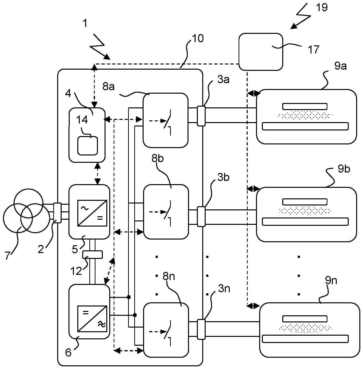
In
Die Leistungswandlereinheit 1 umfasst einen Leistungseingangsanschluss 2 zum Anschluss an ein elektrisches Stromversorgungsnetz 7.
Die Leistungswandlereinheit 1 umfasst ferner eine erste Leistungswandlerstufe 5, die so konfiguriert ist, dass sie die Eingangsleistung an dem Leistungseingangsanschluss 2 in eine Zwischenleistung, vorzugsweise in eine DC-Zwischenkreisleistung 12, umwandelt. Es können auch mehrere erste Leistungswandlerstufen 5 zur Umwandlung der Eingangsleistung am Leistungseingangsanschluss 2 in eine Zwischenleistung, vorzugsweise in eine DC-Zwischenkreisleistung 12, Teil der Leistungswandlereinheit 1 sein und vorzugsweise parallel geschaltet werden.
Die Leistungswandlereinheit 1 umfasst ferner eine weitere Leistungswandlerstufe 6, die der ersten Leistungswandlerstufe 5 nachgeschaltet ist und dazu konfiguriert ist, die Zwischenleistung von der ersten Leistungswandlerstufe in die bipolare Ausgangsleistung umzuwandeln.
Zwischen der Leistungswandlerstufe 5 und der weiteren Leistungswandlerstufe 6 kann ein Energiespeicherelement, wie z.B. eine Induktivität oder ein Kondensator, zur Glättung des Stroms bzw. der Spannung implementiert sein.In
The
The
The
An energy storage element, such as an inductance or a capacitor, can be implemented between the
Die Leistungswandlereinheit 1 umfasst ferner mehrere Schaltmittel 8a, 8b, ... 8n zwischen der Leistungswandlerstufe 6 und den Leistungsausgangsanschlüssen 3a, 3b, .. 3n.
Die Leistungswandlereinheit 1 umfasst ferner eine Steuereinrichtung 4, die dazu ausgebildet ist, die Leistungswandlereinheit 1 zur Abgabe der bipolaren Ausgangsleistung an die Leistungsausgangsanschlüsse 3a, 3b, . 3n zu steuern, unter Verwendung von mindestens einem der folgenden Steuerparametern: Leistung, Spannung, Strom, Erregerfrequenz oder Schwellenwert für Schutzmaßnahmen, so dass mindestens einer der Steuerparameter an einem ersten Leistungsausgangsanschluss 3a sich von dem entsprechenden Steuerparameter an einem anderen Leistungsausgangsanschluss 3b, ... 3n unterscheidet.
In diesem Beispiel hat die Steuereinrichtung 4 Verbindungen zu den Leistungswandlerstufen 5, 6 und den Schaltmitteln 8a, 8b, ... 8n. Einige dieser Anschlüsse können optional sein, wie z. B. der Anschluss an die Leistungswandlerstufen 5. Die Steuereinrichtung 4 kann so konfiguriert sein, dass sie ein Schaltmittel 8a, 8b, ... 8n nur dann von einem geschlossenen Zustand in einen offenen Zustand umschaltet, wenn der Absolutwert des Stroms durch den Schalter kleiner als ein Ampere, vorzugsweise null, ist. Dies hat den Vorteil, dass Schaltmittel verwendet werden können, die nicht für das Schalten höherer Ströme ausgelegt sein müssen. Dadurch wird das Gerät noch preiswerter.The
The
In this example the
Die Plasmabearbeitungseinrichtung 19 umfasst eine Steuerung 17 außerhalb der Leistungswandlereinheit 1. Diese externe Steuerung 17 steuert auch den Plasmaprozess in den Plasmabearbeitungskammern 9a, 9b, .. 9n).The
Die Steuereinrichtung 4 kann auch so konfiguriert sein, dass sie ein Schaltmittel 8a, 8b, ... 8n nur dann von einem offenen Zustand in einen geschlossenen Zustand umschaltet, wenn der Absolutwert der Spannung entlang des offenen Schalters kleiner als 20 Volt, vorzugsweise null, ist. Dies hat den Vorteil, dass Schaltmittel verwendet werden können, die nicht zum Schalten höherer Spannungen ausgelegt sein müssen. Dies macht das Gerät noch preiswerter.
Im Beispiel werden bipolare Transistoren 81, 82, 91, 92 verwendet, wie in
In
Die erste Leistungswandlerstufe 5 kann eine Gleichrichterschaltung, vorzugsweise eine Gleichrichter-Brückenschaltung 50, wie in
Die zweite Leistungswandlerstufe 6 kann eine Schaltbrücke, vorzugsweise eine Vollbrückenschaltung 60, wie in
Die Leistungswandlereinheit 1 kann ein Gehäuse 10 umfassen, das alle anderen Teile der Einheit 1 umschließt. Es kann aus Metall bestehen und somit einen guten Schutz gegen elektromagnetische Störwellen bieten. Der Leistungseingangsanschluss 2 kann direkt mit dem Gehäuse 10 verbunden sein. Die Ausgangsanschlüsse 3a, 3b, ... 3n können ebenfalls direkt mit dem Gehäuse 10 verbunden sein.
In einer Leistungswandlereinheit 1 kann die Stromführungsfähigkeit aller Schaltmittel 8a, 8b ... 8n zusammen höher sein als die maximalen Stromlieferfähigkeiten aller Leistungswandlerstufen 5 zusammen.
In
An den Leistungsausgangsanschlüssen 3a, 3b, ... 3n können Messsensoren zur Erfassung von Spannung, Strom, Frequenz oder Leistung angeschlossen sein (nicht dargestellt). Zur Leistungswandlereinheit 1 können auch mehrere erste Leistungswandlerstufen 5 gehören, die zur Umwandlung der Eingangsleistung am Leistungseingangsanschluss 2 in eine Zwischenleistung, vorzugsweise in DC-Zwischenkreisleistung 12, ausgebildet sind und vorzugsweise parallel geschaltet sind.
In einer Leistungswandlereinheit 1' kann die Stromführungsfähigkeit aller Leistungswandlerstufen 6a, 6b,... 6n zusammen höher sein als die maximalen Stromlieferfähigkeiten aller Leistungswandlerstufen 5 zusammen.The
In the example,
In
The first
The second
The
In a
In
Measuring sensors for detecting voltage, current, frequency or power can be connected to the
In a power converter unit 1', the current carrying capacity of all
Zusätzlich oder alternativ zur Anregung mit unterschiedlichen Frequenzen kann auch die Leistung, die Spannung, der Strom oder der Schwellenwert für Schutzmaßnahmen zwischen zwei verschiedenen Ausgangsanschlüsse 3a, 3b, . 3n oder an zwei verschiedenen Plasmabearbeitungskammern 9a, 9b, .. 9n unterschiedlich sein.
In addition or as an alternative to excitation with different frequencies, the power, the voltage, the current or the threshold value for protective measures between two
In diesem Diagramm sind auch zwei Schwellwertlinien 45, 46 dargestellt. Sie können zur Erkennung eines Plasmazusammenbruchs, wie z. B. eines Lichtbogens oder einer Zündung des Plasmas, verwendet werden, wenn der Effektivwert eines der Parameter Leistung, Spannung oder Strom einen solchen Schwellenwert überschreitet.Two
Die Erfindung arbeitet dergestalt, dass sie mehrere Plasmaprozesse in den mehreren Plasmabearbeitungskammern 9a, 9b, ... 9n mit der Steuereinrichtung 4 steuert, indem eine elektrische Eingangsleistung in eine bipolare Ausgangsleistung, wie in den Signalfolgen 31, 32, 41, 42 dargestellt, umgewandelt wird und diese Ausgangsleistung an die Plasmabearbeitungskammern 9a, 9b, .. 9n abgegeben wird. Die Steuereinrichtung 4 steuert die Leistungswandlereinheit 1 zur Abgabe der bipolaren Ausgangsleistung an die Leistungsausgangsanschlüsse 3a, 3b, . 3n unter Verwendung von mindestens einem der folgenden Steuerparameter: Leistung, Spannung, Strom, Anregungsfrequenz oder Schwellenwert für Schutzmaßnahmen durch Erhalten einer vollständigen Menge Sollwerte für die Parameter der Ausgangsanschlüsse 3a, 3b, ... 3n, wobei die Steuereinrichtung 4 ferner dazu ausgelegt ist, zu berechnen, ob die Leistungswandlereinheit 1, 1' in der Lage ist jeden Sollwert zu jedem Ausgangsanschluss 3a, 3b, ... 3n zu liefern, und, wenn das zutreffend ist, eine Sequenz von Pulsen für die Leistungslieferung zu den Leistungsausgangsanschlüssen 3a, 3b, ... 3n zu errechnen, um die Leistung für den Plasmaprozess bereitzustellen.The invention works in such a way that it controls multiple plasma processes in the multiple
Dazu kann die Steuereinrichtung 4 die Leistungswandlerstufen 6, 6a, 6b, ...6n oder die Schaltmittel 8a, 8b, ... 8n so steuern, dass die Einheit 1 im Betrieb zu einem ersten Zeitpunkt T31 ein erstes Ausgangsleistungssignal an dem ersten Leistungsausgangsanschluss 3a für einen ersten Zeitrahmen T31-T32 und zu einem zweiten Zeitpunkt T41 ein zweites Leistungssignal an einem zweiten Leistungsausgangsanschluss 3b, . 3n für einen zweiten Zeitrahmen T41-T42 liefert, wobei der erste Zeitpunkt T31, T41 sich von dem zweiten Zeitpunkt T32, T42 unterscheidet und/oder der erste Zeitrahmen T31-T32 sich von dem zweiten Zeitrahmen T41-T42 unterscheidet.For this purpose, the
Eine Plasmaeinrichtung 19, wie in
Diese Beschränkungen definieren Bereiche, in denen Betrieb möglich ist, und Bereiche, in denen kein Betrieb möglich ist, im Raum der oben genannten Parameter. Für jede Nachfrage bei der Stromversorgung Leistung bei einem Ausgang oder einer Menge Ausgangsanschlüssen 3a, 3b, ... 3n bereitzustellen, ist die Lage im oder außerhalb des Bereichs, in denen Betrieb möglich ist, zu festzulegen. Daraus resultiert der Bedarf einer Ablaufsteuerung.
Eine Ablaufsteuerung 14 ist Teil der Steuereinrichtung 4. Deren Algorithmus legt für jede Nachfrage zur Leistungswandlereinheit 1 oder für eine Nachfrage zur Änderung von einem oder mehreren Parametern, ob die Nachfrage im möglichen Betriebsbereich liegt, die zu liefernde Ausgangsleistung für jeden der Ausgangsanschlüsse fest. Für einen wie in
- - die Pulsfrequenzen ganzzahlige Vielfache voneinander sind, um Pulsüberlappungen zu vermeiden (für Plasmaeinrichtungen 19' wie in
2 ) - - für überlappende Pulse die gesamt nachgefragte Leistung und Strom nicht das mögliche Maximum übertrifft (für Plasmaeinrichtungen 19' wie in
2 ) - - falls mögliche Maxima für einen begrenzten Zeitraum im Zyklus übertroffen werden, ein Muster ohne dieses Übertreffen gefunden wird (für Plasmaeinrichtungen 19' wie in
2 ) - - die Summe der Pulse in Zeitpunkten plus die Zeit für das Wechseln zwischen Ausgängen kleiner ist als die kleinste Pulszyklusfrequenz (
für Plasmaeinrichtungen 19 wie in1 ) - - ein neu nachgefragtes Ausgangspulsmuster in einem bestimmten Ausgang zu einer richtigen Zeit aktiviert ist, um in existierende Pulsmuster anderer Ausgänge zu passen (
für Plasmaeinrichtungen 19 wie in1 ) - - Gesamtdurchschnittsleistungslimits und -Ströme nicht überschritten werden
- - Eine Warnung dem Benutzer ausgegeben wird, wenn die nachgefragte Sequenz außerhalb des möglichen Bereichs liegt
- - Eine mögliche modifizierte Sequenz dem Benutzer empfohlen wird.
These constraints define areas where operation is possible and areas where operation is not possible in the space of the above parameters. For each power supply demand to provide power at an output or a set of
A
- - the pulse frequencies are integer multiples of each other in order to avoid pulse overlaps (for plasma devices 19' as in
2 ) - - for overlapping pulses, the total power and current demanded does not exceed the possible maximum (for plasma devices 19' as in
2 ) - - if possible maxima are surpassed for a limited period of time in the cycle, a pattern without this surpassing is found (for plasma devices 19' as in
2 ) - - the sum of the pulses in instants plus the time for switching between outputs is less than the smallest pulse cycle frequency (for
plasma devices 19 as in1 ) - - a newly requested output pulse pattern is activated in a specific output at a correct time to fit into existing pulse patterns of other outputs (for
plasma devices 19 as in1 ) - - Overall average power limits and currents are not exceeded
- - A warning is given to the user if the requested sequence is out of range
- - A possible modified sequence is recommended to the user.
ZITATE ENTHALTEN IN DER BESCHREIBUNGQUOTES INCLUDED IN DESCRIPTION
Diese Liste der vom Anmelder aufgeführten Dokumente wurde automatisiert erzeugt und ist ausschließlich zur besseren Information des Lesers aufgenommen. Die Liste ist nicht Bestandteil der deutschen Patent- bzw. Gebrauchsmusteranmeldung. Das DPMA übernimmt keinerlei Haftung für etwaige Fehler oder Auslassungen.This list of the documents cited by the applicant was generated automatically and is included solely for the better information of the reader. The list is not part of the German patent or utility model application. The DPMA assumes no liability for any errors or omissions.
Zitierte PatentliteraturPatent Literature Cited
- US 2014/0357064 A1 [0001]US 2014/0357064 A1 [0001]
- US 2006/0156979 A1 [0001]US 2006/0156979 A1 [0001]
- US 2005/0034667 A1 [0001]US 2005/0034667 A1 [0001]
- US 7396759 B1 [0001]US7396759B1[0001]
- US 2012/0101642 A1 [0001]US 2012/0101642 A1 [0001]
- US 6756318 B2 [0001]US 6756318 B2 [0001]
- US 6495392 B2 [0001]US 6495392 B2 [0001]
- US 6271053 B1 [0001]US6271053B1[0001]
- US 6620299 B1 [0021]US6620299B1 [0021]
Claims (15)
Applications Claiming Priority (2)
| Application Number | Priority Date | Filing Date | Title |
|---|---|---|---|
| EP17168576.1A EP3396700A1 (en) | 2017-04-27 | 2017-04-27 | Power converter unit, plasma processing equipment and method of controlling several plasma processes |
| EP17168576 | 2017-04-27 |
Publications (1)
| Publication Number | Publication Date |
|---|---|
| DE202018006714U1 true DE202018006714U1 (en) | 2022-04-21 |
Family
ID=58668745
Family Applications (1)
| Application Number | Title | Priority Date | Filing Date |
|---|---|---|---|
| DE202018006714.8U Active DE202018006714U1 (en) | 2017-04-27 | 2018-04-27 | Power converter unit, plasma processing device and control device for controlling multiple plasma processes |
Country Status (5)
| Country | Link |
|---|---|
| US (1) | US10971342B2 (en) |
| EP (2) | EP3396700A1 (en) |
| CN (1) | CN110785828B (en) |
| DE (1) | DE202018006714U1 (en) |
| WO (1) | WO2018197702A1 (en) |
Cited By (2)
| Publication number | Priority date | Publication date | Assignee | Title |
|---|---|---|---|---|
| DE102022111529A1 (en) | 2022-05-09 | 2023-11-09 | TRUMPF Hüttinger GmbH + Co. KG | Power supply arrangement, plasma generation device and method for controlling several plasma processes |
| DE102022131435A1 (en) | 2022-11-28 | 2024-05-29 | TRUMPF Hüttinger GmbH + Co. KG | Device for generating a plasma flame, plasma generation device, high-temperature processing plant and corresponding operating method |
Families Citing this family (27)
| Publication number | Priority date | Publication date | Assignee | Title |
|---|---|---|---|---|
| US10510575B2 (en) | 2017-09-20 | 2019-12-17 | Applied Materials, Inc. | Substrate support with multiple embedded electrodes |
| US10555412B2 (en) | 2018-05-10 | 2020-02-04 | Applied Materials, Inc. | Method of controlling ion energy distribution using a pulse generator with a current-return output stage |
| US11476145B2 (en) | 2018-11-20 | 2022-10-18 | Applied Materials, Inc. | Automatic ESC bias compensation when using pulsed DC bias |
| JP7451540B2 (en) | 2019-01-22 | 2024-03-18 | アプライド マテリアルズ インコーポレイテッド | Feedback loop for controlling pulsed voltage waveforms |
| US11508554B2 (en) | 2019-01-24 | 2022-11-22 | Applied Materials, Inc. | High voltage filter assembly |
| KR102886124B1 (en) | 2019-07-29 | 2025-11-14 | 에이이에스 글로벌 홀딩스 피티이 리미티드 | Multiplexed power generator output with channel offset for pulse driving of multiple loads |
| EP3945541A1 (en) * | 2020-07-29 | 2022-02-02 | TRUMPF Huettinger Sp. Z o. o. | Pulsing assembly, power supply arrangement and method using the assembly |
| US11462388B2 (en) | 2020-07-31 | 2022-10-04 | Applied Materials, Inc. | Plasma processing assembly using pulsed-voltage and radio-frequency power |
| US11901157B2 (en) | 2020-11-16 | 2024-02-13 | Applied Materials, Inc. | Apparatus and methods for controlling ion energy distribution |
| US11798790B2 (en) | 2020-11-16 | 2023-10-24 | Applied Materials, Inc. | Apparatus and methods for controlling ion energy distribution |
| US11495470B1 (en) | 2021-04-16 | 2022-11-08 | Applied Materials, Inc. | Method of enhancing etching selectivity using a pulsed plasma |
| US11791138B2 (en) | 2021-05-12 | 2023-10-17 | Applied Materials, Inc. | Automatic electrostatic chuck bias compensation during plasma processing |
| US11948780B2 (en) | 2021-05-12 | 2024-04-02 | Applied Materials, Inc. | Automatic electrostatic chuck bias compensation during plasma processing |
| US11967483B2 (en) | 2021-06-02 | 2024-04-23 | Applied Materials, Inc. | Plasma excitation with ion energy control |
| US20220399186A1 (en) | 2021-06-09 | 2022-12-15 | Applied Materials, Inc. | Method and apparatus to reduce feature charging in plasma processing chamber |
| US11984306B2 (en) | 2021-06-09 | 2024-05-14 | Applied Materials, Inc. | Plasma chamber and chamber component cleaning methods |
| US12148595B2 (en) | 2021-06-09 | 2024-11-19 | Applied Materials, Inc. | Plasma uniformity control in pulsed DC plasma chamber |
| US11810760B2 (en) | 2021-06-16 | 2023-11-07 | Applied Materials, Inc. | Apparatus and method of ion current compensation |
| US11569066B2 (en) | 2021-06-23 | 2023-01-31 | Applied Materials, Inc. | Pulsed voltage source for plasma processing applications |
| US11776788B2 (en) | 2021-06-28 | 2023-10-03 | Applied Materials, Inc. | Pulsed voltage boost for substrate processing |
| US11476090B1 (en) | 2021-08-24 | 2022-10-18 | Applied Materials, Inc. | Voltage pulse time-domain multiplexing |
| US12106938B2 (en) | 2021-09-14 | 2024-10-01 | Applied Materials, Inc. | Distortion current mitigation in a radio frequency plasma processing chamber |
| US11694876B2 (en) | 2021-12-08 | 2023-07-04 | Applied Materials, Inc. | Apparatus and method for delivering a plurality of waveform signals during plasma processing |
| US11972924B2 (en) | 2022-06-08 | 2024-04-30 | Applied Materials, Inc. | Pulsed voltage source for plasma processing applications |
| US12315732B2 (en) | 2022-06-10 | 2025-05-27 | Applied Materials, Inc. | Method and apparatus for etching a semiconductor substrate in a plasma etch chamber |
| US12272524B2 (en) | 2022-09-19 | 2025-04-08 | Applied Materials, Inc. | Wideband variable impedance load for high volume manufacturing qualification and on-site diagnostics |
| US12111341B2 (en) | 2022-10-05 | 2024-10-08 | Applied Materials, Inc. | In-situ electric field detection method and apparatus |
Citations (9)
| Publication number | Priority date | Publication date | Assignee | Title |
|---|---|---|---|---|
| US6271053B1 (en) | 1999-03-25 | 2001-08-07 | Kaneka Corporation | Method of manufacturing a thin film solar battery module |
| US6495392B2 (en) | 1999-08-24 | 2002-12-17 | Canon Kabushiki Kaisha | Process for producing a semiconductor device |
| US6620299B1 (en) | 1998-12-28 | 2003-09-16 | Fraunhofer-Gesellschaft zur Förderung der angewandten Forschung e.V. | Process and device for the coating of substrates by means of bipolar pulsed magnetron sputtering and the use thereof |
| US6756318B2 (en) | 2001-09-10 | 2004-06-29 | Tegal Corporation | Nanolayer thick film processing system and method |
| US20050034667A1 (en) | 2003-08-14 | 2005-02-17 | Asm Japan K.K. | Method and apparatus for forming silicon-containing insulation film having low dielectric constant |
| US20060156979A1 (en) | 2004-11-22 | 2006-07-20 | Applied Materials, Inc. | Substrate processing apparatus using a batch processing chamber |
| US7396759B1 (en) | 2004-11-03 | 2008-07-08 | Novellus Systems, Inc. | Protection of Cu damascene interconnects by formation of a self-aligned buffer layer |
| US20120101642A1 (en) | 2010-10-20 | 2012-04-26 | Huettinger Elektronik Gmbh + Co. Kg | Plasma and Induction Heating Power Supply Systems and Related Methods |
| US20140357064A1 (en) | 2013-05-31 | 2014-12-04 | Novellus Systems, Inc. | Tensile stressed doped amorphous silicon |
Family Cites Families (10)
| Publication number | Priority date | Publication date | Assignee | Title |
|---|---|---|---|---|
| DE10306347A1 (en) * | 2003-02-15 | 2004-08-26 | Hüttinger Elektronik GmbH & Co. KG | Controlling supply of power from AC supply to two consumers in plasma process, by adjusting supplied power if actual power deviates from set value |
| US20070045111A1 (en) * | 2004-12-24 | 2007-03-01 | Alfred Trusch | Plasma excitation system |
| EP1675155B1 (en) * | 2004-12-24 | 2012-01-25 | HÜTTINGER Elektronik GmbH + Co. KG | Plasma excitation system |
| JP5124344B2 (en) * | 2008-05-26 | 2013-01-23 | 株式会社アルバック | Bipolar pulse power supply, power supply apparatus comprising a plurality of bipolar pulse power supplies, and output method |
| DE102014209469A1 (en) * | 2014-05-19 | 2015-11-19 | TRUMPF Hüttinger GmbH + Co. KG | Control arrangement, control system and high-frequency power generation device |
| US9263350B2 (en) * | 2014-06-03 | 2016-02-16 | Lam Research Corporation | Multi-station plasma reactor with RF balancing |
| CN105261545B (en) * | 2014-07-18 | 2017-08-22 | 中微半导体设备(上海)有限公司 | Multiprocessing area plasma body processing unit and plasma process monitoring method |
| US9667303B2 (en) * | 2015-01-28 | 2017-05-30 | Lam Research Corporation | Dual push between a host computer system and an RF generator |
| US9596744B2 (en) * | 2015-03-31 | 2017-03-14 | Lam Research Corporation | Radio frequency generator having multiple mutually exclusive oscillators for use in plasma processing |
| US9721758B2 (en) * | 2015-07-13 | 2017-08-01 | Mks Instruments, Inc. | Unified RF power delivery single input, multiple output control for continuous and pulse mode operation |
-
2017
- 2017-04-27 EP EP17168576.1A patent/EP3396700A1/en not_active Withdrawn
-
2018
- 2018-04-27 CN CN201880040274.XA patent/CN110785828B/en active Active
- 2018-04-27 WO PCT/EP2018/060954 patent/WO2018197702A1/en not_active Ceased
- 2018-04-27 EP EP18722446.4A patent/EP3616234B1/en active Active
- 2018-04-27 DE DE202018006714.8U patent/DE202018006714U1/en active Active
-
2019
- 2019-10-25 US US16/664,207 patent/US10971342B2/en active Active
Patent Citations (9)
| Publication number | Priority date | Publication date | Assignee | Title |
|---|---|---|---|---|
| US6620299B1 (en) | 1998-12-28 | 2003-09-16 | Fraunhofer-Gesellschaft zur Förderung der angewandten Forschung e.V. | Process and device for the coating of substrates by means of bipolar pulsed magnetron sputtering and the use thereof |
| US6271053B1 (en) | 1999-03-25 | 2001-08-07 | Kaneka Corporation | Method of manufacturing a thin film solar battery module |
| US6495392B2 (en) | 1999-08-24 | 2002-12-17 | Canon Kabushiki Kaisha | Process for producing a semiconductor device |
| US6756318B2 (en) | 2001-09-10 | 2004-06-29 | Tegal Corporation | Nanolayer thick film processing system and method |
| US20050034667A1 (en) | 2003-08-14 | 2005-02-17 | Asm Japan K.K. | Method and apparatus for forming silicon-containing insulation film having low dielectric constant |
| US7396759B1 (en) | 2004-11-03 | 2008-07-08 | Novellus Systems, Inc. | Protection of Cu damascene interconnects by formation of a self-aligned buffer layer |
| US20060156979A1 (en) | 2004-11-22 | 2006-07-20 | Applied Materials, Inc. | Substrate processing apparatus using a batch processing chamber |
| US20120101642A1 (en) | 2010-10-20 | 2012-04-26 | Huettinger Elektronik Gmbh + Co. Kg | Plasma and Induction Heating Power Supply Systems and Related Methods |
| US20140357064A1 (en) | 2013-05-31 | 2014-12-04 | Novellus Systems, Inc. | Tensile stressed doped amorphous silicon |
Cited By (2)
| Publication number | Priority date | Publication date | Assignee | Title |
|---|---|---|---|---|
| DE102022111529A1 (en) | 2022-05-09 | 2023-11-09 | TRUMPF Hüttinger GmbH + Co. KG | Power supply arrangement, plasma generation device and method for controlling several plasma processes |
| DE102022131435A1 (en) | 2022-11-28 | 2024-05-29 | TRUMPF Hüttinger GmbH + Co. KG | Device for generating a plasma flame, plasma generation device, high-temperature processing plant and corresponding operating method |
Also Published As
| Publication number | Publication date |
|---|---|
| EP3616234B1 (en) | 2021-10-13 |
| US10971342B2 (en) | 2021-04-06 |
| CN110785828B (en) | 2022-04-26 |
| EP3616234A1 (en) | 2020-03-04 |
| US20200066498A1 (en) | 2020-02-27 |
| WO2018197702A1 (en) | 2018-11-01 |
| EP3396700A1 (en) | 2018-10-31 |
| CN110785828A (en) | 2020-02-11 |
Similar Documents
| Publication | Publication Date | Title |
|---|---|---|
| DE202018006714U1 (en) | Power converter unit, plasma processing device and control device for controlling multiple plasma processes | |
| DE202018006711U1 (en) | Power converter unit, plasma processing device and control device for controlling multiple plasma processes | |
| DE202018006738U1 (en) | Power converter unit, plasma processing device and control device for controlling multiple plasma processes | |
| EP1249923A2 (en) | Circuit for transformation of AC-voltage into DC-voltage | |
| DE102019106485B4 (en) | Weissach rectifier arrangement | |
| DE102013203706B3 (en) | Method of operating modular high frequency converter mounted in e.g. electric vehicle, involves replacing switching position model parameters that represent influence of switch positions of input-side half-bridge by related duty cycle | |
| DE112014002478T5 (en) | Device and method for charging a vehicle battery from the power grid | |
| WO2003017460A1 (en) | Device and method for monitoring the connection of an electrical supply unit | |
| EP1593143A2 (en) | Power supply control unit | |
| EP2654190B1 (en) | Method for operating an electric circuit | |
| WO2018206201A1 (en) | Battery device having at least one module string, in which module string module units are interconnected one after the other in a row, and motor vehicle and operating method for the battery device | |
| DE102004025597A1 (en) | Power Factor Correction Method and Circuit (PFC) | |
| DE102018204585A1 (en) | Plasma generator, plasma treatment apparatus and method for pulsed supply of electrical power | |
| DE102014201615B4 (en) | Multiphase DC voltage converter and method for operating a multiphase DC voltage converter | |
| WO2017084863A1 (en) | Method for detecting an error in a generator unit | |
| WO2022167136A1 (en) | Modular battery storage system with rechargeable energy storage modules, and method for operating the battery storage system | |
| EP3377911A1 (en) | Method for detecting an error in a generator unit | |
| EP1442512A2 (en) | Voltage converter | |
| EP2820752B1 (en) | Semi-active front end converter with vector control of reactive power | |
| EP3043461B1 (en) | Supply circuit for supplying a welding device | |
| EP3218980B1 (en) | Control of the power transmission in a dc grid | |
| DE102022111529A1 (en) | Power supply arrangement, plasma generation device and method for controlling several plasma processes | |
| EP3939138A1 (en) | Method for three-phase supply into an alternating voltage network, and three-phase inverter | |
| DE102017207297A1 (en) | Method for controlling a power converter, control device for a power converter and power converter | |
| DE102013109364A1 (en) | Variable buck converter and battery charging station with such a buck converter |
Legal Events
| Date | Code | Title | Description |
|---|---|---|---|
| R150 | Utility model maintained after payment of first maintenance fee after three years | ||
| R207 | Utility model specification | ||
| R151 | Utility model maintained after payment of second maintenance fee after six years |