DE202016105042U1 - Optoelectronic sensor - Google Patents
Optoelectronic sensor Download PDFInfo
- Publication number
- DE202016105042U1 DE202016105042U1 DE202016105042.1U DE202016105042U DE202016105042U1 DE 202016105042 U1 DE202016105042 U1 DE 202016105042U1 DE 202016105042 U DE202016105042 U DE 202016105042U DE 202016105042 U1 DE202016105042 U1 DE 202016105042U1
- Authority
- DE
- Germany
- Prior art keywords
- hood
- sensor
- support element
- light
- scanning unit
- Prior art date
- Legal status (The legal status is an assumption and is not a legal conclusion. Google has not performed a legal analysis and makes no representation as to the accuracy of the status listed.)
- Expired - Lifetime
Links
- 230000005693 optoelectronics Effects 0.000 title claims abstract description 8
- 238000011156 evaluation Methods 0.000 claims abstract description 12
- 229920003023 plastic Polymers 0.000 claims description 6
- 230000000737 periodic effect Effects 0.000 claims description 2
- 230000033001 locomotion Effects 0.000 description 8
- 238000012544 monitoring process Methods 0.000 description 7
- 230000005540 biological transmission Effects 0.000 description 6
- 239000004033 plastic Substances 0.000 description 5
- 230000001681 protective effect Effects 0.000 description 5
- 238000004519 manufacturing process Methods 0.000 description 4
- 239000002184 metal Substances 0.000 description 4
- 230000008901 benefit Effects 0.000 description 3
- 238000013461 design Methods 0.000 description 3
- 230000017525 heat dissipation Effects 0.000 description 3
- 238000000034 method Methods 0.000 description 3
- 230000002950 deficient Effects 0.000 description 2
- 238000005516 engineering process Methods 0.000 description 2
- 238000005259 measurement Methods 0.000 description 2
- 230000003287 optical effect Effects 0.000 description 2
- 230000005855 radiation Effects 0.000 description 2
- 230000000284 resting effect Effects 0.000 description 2
- BUHVIAUBTBOHAG-FOYDDCNASA-N (2r,3r,4s,5r)-2-[6-[[2-(3,5-dimethoxyphenyl)-2-(2-methylphenyl)ethyl]amino]purin-9-yl]-5-(hydroxymethyl)oxolane-3,4-diol Chemical compound COC1=CC(OC)=CC(C(CNC=2C=3N=CN(C=3N=CN=2)[C@H]2[C@@H]([C@H](O)[C@@H](CO)O2)O)C=2C(=CC=CC=2)C)=C1 BUHVIAUBTBOHAG-FOYDDCNASA-N 0.000 description 1
- 238000012935 Averaging Methods 0.000 description 1
- 241000183024 Populus tremula Species 0.000 description 1
- 239000004809 Teflon Substances 0.000 description 1
- 229920006362 Teflon® Polymers 0.000 description 1
- 230000015556 catabolic process Effects 0.000 description 1
- 239000011248 coating agent Substances 0.000 description 1
- 238000000576 coating method Methods 0.000 description 1
- 238000004891 communication Methods 0.000 description 1
- 239000004020 conductor Substances 0.000 description 1
- 230000007547 defect Effects 0.000 description 1
- 230000006735 deficit Effects 0.000 description 1
- 238000009826 distribution Methods 0.000 description 1
- 230000036039 immunity Effects 0.000 description 1
- 239000000463 material Substances 0.000 description 1
- 238000013021 overheating Methods 0.000 description 1
- 230000035699 permeability Effects 0.000 description 1
- 230000035939 shock Effects 0.000 description 1
- 230000003595 spectral effect Effects 0.000 description 1
- 238000003860 storage Methods 0.000 description 1
- 230000009466 transformation Effects 0.000 description 1
- 230000007704 transition Effects 0.000 description 1
Images

Classifications
-
- G—PHYSICS
- G01—MEASURING; TESTING
- G01S—RADIO DIRECTION-FINDING; RADIO NAVIGATION; DETERMINING DISTANCE OR VELOCITY BY USE OF RADIO WAVES; LOCATING OR PRESENCE-DETECTING BY USE OF THE REFLECTION OR RERADIATION OF RADIO WAVES; ANALOGOUS ARRANGEMENTS USING OTHER WAVES
- G01S7/00—Details of systems according to groups G01S13/00, G01S15/00, G01S17/00
- G01S7/48—Details of systems according to groups G01S13/00, G01S15/00, G01S17/00 of systems according to group G01S17/00
- G01S7/481—Constructional features, e.g. arrangements of optical elements
- G01S7/4817—Constructional features, e.g. arrangements of optical elements relating to scanning
-
- G—PHYSICS
- G01—MEASURING; TESTING
- G01S—RADIO DIRECTION-FINDING; RADIO NAVIGATION; DETERMINING DISTANCE OR VELOCITY BY USE OF RADIO WAVES; LOCATING OR PRESENCE-DETECTING BY USE OF THE REFLECTION OR RERADIATION OF RADIO WAVES; ANALOGOUS ARRANGEMENTS USING OTHER WAVES
- G01S17/00—Systems using the reflection or reradiation of electromagnetic waves other than radio waves, e.g. lidar systems
- G01S17/02—Systems using the reflection of electromagnetic waves other than radio waves
- G01S17/06—Systems determining position data of a target
- G01S17/42—Simultaneous measurement of distance and other co-ordinates
-
- G—PHYSICS
- G01—MEASURING; TESTING
- G01S—RADIO DIRECTION-FINDING; RADIO NAVIGATION; DETERMINING DISTANCE OR VELOCITY BY USE OF RADIO WAVES; LOCATING OR PRESENCE-DETECTING BY USE OF THE REFLECTION OR RERADIATION OF RADIO WAVES; ANALOGOUS ARRANGEMENTS USING OTHER WAVES
- G01S7/00—Details of systems according to groups G01S13/00, G01S15/00, G01S17/00
- G01S7/48—Details of systems according to groups G01S13/00, G01S15/00, G01S17/00 of systems according to group G01S17/00
- G01S7/481—Constructional features, e.g. arrangements of optical elements
- G01S7/4811—Constructional features, e.g. arrangements of optical elements common to transmitter and receiver
- G01S7/4813—Housing arrangements
Landscapes
- Engineering & Computer Science (AREA)
- Physics & Mathematics (AREA)
- Computer Networks & Wireless Communication (AREA)
- General Physics & Mathematics (AREA)
- Radar, Positioning & Navigation (AREA)
- Remote Sensing (AREA)
- Electromagnetism (AREA)
- Optical Radar Systems And Details Thereof (AREA)
Abstract
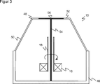
Optoelektronischer Sensor (10), insbesondere Laserscanner, zur Erfassung von Objekten in einem Überwachungsbereich (22), wobei der Sensor (10) einen Lichtsender (24) zum Aussenden von Sendelicht (28), einen Antrieb (16), eine mit Hilfe des Antriebs (16) bewegbare Abtasteinheit (12) zur periodischen Abtastung mit dem Sendelicht (28), einen Lichtempfänger (34) zum Erzeugen eines Empfangssignals aus von Objekten in dem Überwachungsbereich (22) remittierten Licht (30), eine Auswertungseinheit (40) zur Erfassung von Informationen über Objekte in dem Überwachungsbereich (22) anhand des Empfangssignals und ein Gehäuse (46) mit einer Haube (48) aufweist, wobei die Haube (48) durch ein Stützelement (54) zusätzlich abgestützt ist, dadurch gekennzeichnet, dass der Antrieb (16) eine Hohlwelle (18) aufweist und dass das Stützelement (54) durch die Hohlwelle (18) geführt ist.Optoelectronic sensor (10), in particular laser scanner, for detecting objects in a surveillance area (22), wherein the sensor (10) comprises a light transmitter (24) for emitting transmitted light (28), a drive (16), one with the aid of the drive (16) a movable scanning unit (12) for periodically scanning the transmitted light (28), a light receiver (34) for generating a received signal from objects (30) remitted by objects in the surveillance area (22), an evaluation unit (40) for detecting Information about objects in the surveillance area (22) based on the received signal and a housing (46) with a hood (48), wherein the hood (48) is additionally supported by a support element (54), characterized in that the drive (16 ) has a hollow shaft (18) and that the support element (54) through the hollow shaft (18) is guided.
Description
Die Erfindung betrifft einen optoelektronischen Sensor zur Erfassung von Objekten in einem Überwachungsbereich nach dem Oberbegriff von Anspruch 1. The invention relates to an optoelectronic sensor for detecting objects in a surveillance area according to the preamble of claim 1.
Für Abstandsmessungen, die einen großen horizontalen Winkelbereich des Messsystems erforderlich machen, eignen sich optoelektronische Systeme und besonders Laserscanner. In einem Laserscanner überstreicht ein von einem Laser erzeugter Lichtstrahl mit Hilfe einer Ablenkeinheit periodisch einen Überwachungsbereich. Das Licht wird an Objekten in dem Überwachungsbereich remittiert und in dem Scanner ausgewertet. Aus der Winkelstellung der Ablenkeinheit wird auf die Winkellage des Objektes und aus der Lichtlaufzeit unter Verwendung der Lichtgeschwindigkeit zusätzlich auf die Entfernung des Objektes von dem Laserscanner geschlossen. For distance measurements that require a large horizontal angle range of the measuring system, optoelectronic systems and especially laser scanners are suitable. In a laser scanner, a laser beam generated by a laser periodically sweeps over a monitoring area by means of a deflection unit. The light is remitted to objects in the surveillance area and evaluated in the scanner. From the angular position of the deflection is on the angular position of the object and from the light transit time using the speed of light in addition to the removal of the object from the laser scanner closed.
Mit den Winkel- und Entfernungsangaben ist der Ort eines Objektes in dem Überwachungsbereich in zweidimensionalen Polarkoordinaten erfasst. Damit lassen sich die Positionen von Objekten ermitteln oder durch mehrere Abtastungen desselben Objekts an verschiedenen Stellen dessen Kontur bestimmen. Die dritte Raumkoordinate kann durch eine Relativbewegung in Querrichtung ebenfalls erfasst werden, beispielsweise durch einen weiteren Bewegungsfreiheitsgrad der Ablenkeinheit in dem Laserscanner oder indem das Objekt relativ zu dem Laserscanner befördert wird. So können auch dreidimensionale Konturen ausgemessen werden. With the angle and distance indications, the location of an object in the surveillance area is recorded in two-dimensional polar coordinates. In this way, the positions of objects can be determined or, by means of several scans of the same object, determined at different points of its contour. The third spatial coordinate can also be detected by a relative movement in the transverse direction, for example by a further degree of freedom of movement of the deflection unit in the laser scanner or by the object being conveyed relative to the laser scanner. Thus, even three-dimensional contours can be measured.
Neben solchen Messanwendungen werden Laserscanner auch in der Sicherheitstechnik zur Überwachung einer Gefahrenquelle eingesetzt, wie sie beispielsweise eine gefährliche Maschine darstellt. Ein derartiger Sicherheitslaserscanner ist aus der
Die Abtastung der Überwachungsebene in einem Laserscanner wird üblicherweise dadurch erreicht, dass der Sendestrahl auf einen rotierenden Drehspiegel trifft. Lichtsender, Lichtempfänger sowie zugehörige Elektronik und Optik sind dabei im Gerät fest montiert und vollziehen die Drehbewegung nicht mit. Es ist aber auch bekannt, den Drehspiegel durch eine mitbewegte Abtasteinheit zu ersetzen. Beispielsweise rotiert in der
Der Laserscanner
Die Haube
Da außerdem die Haube
Neben der geschilderten Durchbiegung besonders bei punktueller Belastung nahe des Zentrums der Haubenmitte ist ein weiterer Nachteil der Haube
Es ist denkbar, die Haube
Daher ist Aufgabe der Erfindung, einen gattungsgemäßen Sensor mit verbesserter Stabilität anzugeben. Therefore object of the invention to provide a generic sensor with improved stability.
Diese Aufgabe wird durch einen optoelektronischen Sensor zur Erfassung von Objekten in einem Überwachungsbereich nach Anspruch 1 gelöst. Der Sensor weist einen Lichtsender und einen Lichtempfänger auf, um den Überwachungsbereich abzutasten, wobei ein Antrieb und eine davon bewegte Abtasteinheit für eine periodische Abtastbewegung sorgen. Der Sensor weist ein Gehäuse mit einer Haube auf, die den oberen Teil des Gehäuses bildet. Diese Haube ist vorzugsweise in sich schon stabil, aber gerade bei großem Durchmesser der Haube genügt die Abstützung durch die eigene Festigkeit nicht überall, weshalb sie zusätzlich durch ein Stütz-element abgestützt ist. Die Erfindung geht nun von dem Grundgedanken aus, das Stützelement in einer Hohlwelle des Antriebs unterzubringen. This object is achieved by an optoelectronic sensor for detecting objects in a surveillance area according to claim 1. The sensor includes a light emitter and a light receiver for scanning the monitoring area, with a drive and a scanning unit moved thereby providing a periodic scanning movement. The sensor has a housing with a hood which forms the upper part of the housing. This hood is preferably already stable in itself, but just with a large diameter of the hood, the support by its own strength is not enough everywhere, which is why it is additionally supported by a support element. The invention is based on the basic idea of accommodating the support element in a hollow shaft of the drive.
Die Erfindung hat den Vorteil, dass die Haube mit einer einfachen Maßnahme ausreichend gestützt ist, um Kollisionen der Haube mit beweglichen Teilen, wie der Abtasteinheit oder der Hohlwelle, zuverlässig zu vermeiden. Zugleich wird die Haube und damit der ganze Sensor im Feld robuster, hat eine höhere Schock- und Schwing-Festigkeit, und besonders die Outdoorfähigkeit oder die Einsatzmöglichkeiten in anspruchsvollen Umgebungen, in denen der Sensor nicht vor mechanischen Belastungen geschützt werden kann, erhöht sich somit erheblich. Ein Ausfall durch eine defekte Haube oder ein defektes Gerät wird wesentlich unwahrscheinlicher. The invention has the advantage that the hood is sufficiently supported with a simple measure to reliably avoid collisions of the hood with moving parts, such as the scanning unit or the hollow shaft. At the same time, the hood and thus the whole sensor in the field becomes more robust, has a higher shock and vibration resistance, and in particular the outdoor capability or the application possibilities in demanding environments, in which the sensor can not be protected against mechanical loads, increases considerably , A failure due to a defective hood or a defective device is much less likely.
Die Haube ist bevorzugt als Rotationskörper mit einer Seitenwand und einem Deckelbereich ausgebildet. Die Seitenwand bildet beispielsweise einen Kreiszylinder, einen Kegelstumpf oder einen Kugelabschnitt, es sind aber auch kompliziertere Konturen beispielsweise wie bei einem Kelch denkbar. Nach oben hin wird dies dann durch einen Deckelbereich abgeschlossen, der kreisförmig sein, aber auch eine Wölbung aufweisen kann. The hood is preferably designed as a rotary body with a side wall and a lid portion. The side wall forms for example a circular cylinder, a truncated cone or a spherical section, but there are also more complicated contours, for example, conceivable as in a goblet. At the top, this is then completed by a lid area, which may be circular, but may also have a curvature.
Die Haube weist bevorzugt eine Frontscheibe als Austrittsbereich für das Sendelicht und Eintrittsbereich für das remittierte Licht auf. Diese Frontscheibe ist nochmals bevorzugt integraler Bestandteil der Haube, insbesondere der Seitenwand. The hood preferably has a front screen as an exit region for the transmitted light and the entry region for the remitted light. This front screen is again preferably an integral part of the hood, in particular the side wall.
Die Haube ist bevorzugt aus für das Sendelicht transparentem Kunststoff hergestellt. Die Transparenzeigenschaft gilt damit natürlich auch für das remittierte Empfangslicht, da es dieselbe Wellenlänge aufweist. Damit gewinnt die Haube die Eigenschaften, um zugleich als Frontscheide zu dienen. Für das bloße Auge muss allerdings die Haube keineswegs transparent sein, sondern ist beispielsweise schwarz und undurchsichtig, da für das Sendelicht häufig ein Spektralbereich außerhalb des sichtbaren Bereichs genutzt wird, insbesondere Infrarotlicht. The hood is preferably made of plastic transparent to transmitted light. Of course, the transparency property also applies to the reflected reception light, since it has the same wavelength. Thus, the hood wins the properties in order to serve as a front sheath at the same time. For the naked eye, however, the hood must by no means be transparent, but is, for example, black and opaque, since the transmitted light often uses a spectral range outside the visible range, in particular infrared light.
Die Haube ist vorzugsweise ein einziges Bauteil, keine Baugruppe aus mehreren Elementen, um die Herstellung der Haube und deren Handhabung während der Montage des Sensors zu vereinfachen. The hood is preferably a single component, not a multi-element assembly, to facilitate manufacture of the hood and its handling during assembly of the sensor.
Bevorzugt stützt das Stützelement die Haube zentral ab. Der Abstützbereich an der Haube befindet sich dabei insbesondere etwa in der Mitte des Deckelbereichs. Preferably, the support element centrally supports the hood. The support area on the hood is located in particular approximately in the middle of the lid area.
Das Stützelement ist bevorzugt an der Haube fixiert. Durch die Führung in der Hohlwelle ist ein Mitdrehen des Stützelements nicht erforderlich, es kann vielmehr mit dem ruhenden Sensor fest verbunden sein. Dementsprechend ist auch eine einfache und stabile Fixierung an der Haube ohne drehbare Lagerung oder dergleichen möglich. The support element is preferably fixed to the hood. By guiding in the hollow shaft co-rotation of the support member is not required, but it may be firmly connected to the stationary sensor. Accordingly, a simple and stable fixation on the hood without rotatable storage or the like is possible.
Das Stützelement ist bevorzugt stangenförmig ausgebildet. Ein derartiges Stützelement ist stangenförmig oder eine Art Stützstift. Das ermöglicht eine einfache Ausgestaltung des Stützelements und Führung durch die Hohlwelle. Die praktisch punktförmige Abstützung genügt häufig schon, um das Problem einer instabilen Haube zu lösen. Außerdem ist es möglich, den Haubenbereich um den Abstützpunkt zu verstärken und so die Kräfte im Deckelbereich der Haube zu verteilen. The support element is preferably rod-shaped. Such a support element is rod-shaped or a kind of support pin. This allows a simple configuration of the support element and guidance through the hollow shaft. The practically punctiform support is often enough to solve the problem of an unstable hood. It is also possible to strengthen the hood area around the support point and thus to distribute the forces in the cover area of the hood.
Das Stützelement ist bevorzugt an einem Boden des Gehäuses abgestützt. Dort können die Stützkräfte leicht aufgenommen werden. Vorzugsweise läuft das Stützelement auf diese Weise einmal über die ganze Höhe des Sensors von Boden bis Deckelbereich der Haube. The support element is preferably supported on a bottom of the housing. There, the support forces can be easily absorbed. Preferably, the support element runs in this way once over the entire height of the sensor from the bottom to the lid portion of the hood.
Das Stützelement ist bevorzugt leitend. Dazu kann es aus Metall hergestellt sein oder einen Leiter aufweisen, auch in Form einer leitenden Beschichtung. Die leitenden Eigenschaften sollen in erster Linie dazu dienen, Bereiche des Sensors auf Masse zu legen, um die EMV-Festigkeit zu unterstützen. Denkbar ist auch eine verbesserte Wärmeverteilung oder Wärmeabgabe. Auch eine Strom- oder Signalleitung ist denkbar, beispielsweise indem ein drahtloser Energie- oder Datenaustausch zwischen einer rotierenden Abtasteinheit zum Deckelbereich der Haube hin vorgesehen ist und dann das Stützelement die weitere Verbindung in den Bodenbereich des Sensors herstellt. The support element is preferably conductive. For this purpose, it may be made of metal or have a conductor, also in the form of a conductive coating. The primary purpose of the conductive features is to ground regions of the sensor to aid in EMC immunity. It is also conceivable improved heat distribution or heat dissipation. A power or signal line is also conceivable, for example by providing a wireless energy or data exchange between a rotating scanning unit to the lid portion of the hood and then the support member produces the further connection in the bottom region of the sensor.
Die Haube weist bevorzugt einen leitenden Teilbereich auf. Dieser leitende Teilbereich befindet sich vorzugsweise im Deckelbereich oder bildet den Deckelbereich und schließt nochmals bevorzugt den Kontaktbereich mit dem Stützelement ein. Der leitende Teilbereich ist beispielsweise aus Metall hergestellt, weist eine Metallplatte auf oder ist leitend beschichtet. Bei einer herkömmlichen Haube würde das Zusatzgewicht für die leitenden Eigenschaften die Probleme mit den Instabilitäten noch verschärfen, aber bei geeigneter Auslegung des Stützelements ist das erfindungsgemäß ohne weiteres möglich. Der leitende Teilbereich dient als elektrische Abschirmung und zur Wärmeabfuhr an die Umgebung. Damit werden die EMV-Eigenschaften verbessert, und der Sensor kann in einem erweiterten Temperaturbereich eingesetzt werden. Vorzugsweise ist der leitende Teilbereich auf Masse gelegt, insbesondere über ein ebenfalls leitendes Stützelement. The hood preferably has a conductive portion. This conductive subregion is preferably located in the lid region or forms the lid region and, more preferably, includes the contact region with the support element. The conductive portion is made for example of metal, has a metal plate or is conductive coated. In a conventional hood, the additional weight for the conductive properties would aggravate the problems with the instabilities, but with a suitable design of the support element according to the invention is readily possible. The conductive part serves as electrical shielding and heat dissipation to the environment. This improves the EMC properties and allows the sensor to be used in an extended temperature range. Preferably, the conductive portion is grounded, in particular via a likewise conductive support element.
Die Abtasteinheit weist bevorzugt den Lichtsender und/oder den Lichtempfänger auf. Damit wird die Abtasteinheit zu einem rotierenden Messkopf. Mit Lichtsender und Lichtempfänger sind vorzugsweise auch zugehörige Sende- und Empfangsoptiken sowie zumindest ein Teil der Sende- und Empfangselektronik sowie möglicherweise der Auswertungseinheit in der Abtasteinheit untergebracht. The scanning unit preferably has the light transmitter and / or the light receiver. This turns the scanning unit into a rotating measuring head. With light transmitter and light receiver preferably associated transmitting and receiving optics and at least a portion of the transmitting and receiving electronics and possibly the evaluation unit are housed in the scanning unit.
Der Sensor ist bevorzugt ein entfernungsmessender Sensor, indem die Auswertungseinheit die Lichtlaufzeit zwischen Aussenden des Lichtsignals und Empfang des remittierten Lichts und daraus die Entfernung eines Objekts bestimmt. Damit können wesentlich genauere Objektinformationen gewonnen werden als durch bloße Feststellung der Anwesenheit von Objekten. The sensor is preferably a distance-measuring sensor in that the evaluation unit determines the light transit time between emission of the light signal and reception of the remitted light and, therefrom, the removal of an object. This allows much more accurate object information to be obtained than simply detecting the presence of objects.
Vorzugsweise ist eine Winkelmesseinheit zur Erfassung der Winkelstellung der Abtasteinheit vorgesehen. Insgesamt stehen dann für erfasste Objekte vollständige zweidimensionale Positionskoordinaten zur Verfügung. Im Falle eines räumlich ausgedehnten Überwachungsbereichs durch Bewegung der Abtasteinheit in zwei Achsen wird vorzugsweise auch der jeweilige Kippwinkel der Abtasteinheit erfasst, so dass dann insgesamt dreidimensionale Kugelkoordinaten erhalten werden, welche die Objektposition innerhalb des Überwachungsbereichs ebenfalls vollständig beschreiben. Preferably, an angle measuring unit is provided for detecting the angular position of the scanning unit. Overall, complete two-dimensional position coordinates are then available for detected objects. In the case of a spatially extended monitoring area by movement of the scanning unit in two axes, the respective tilt angle of the scanning unit is preferably detected, so that then a total of three-dimensional spherical coordinates are obtained, which also completely describe the object position within the monitoring area.
Der Sensor ist bevorzugt als Sicherheitssensor ausgebildet und weist einen Sicherheitsausgang auf, wobei die Auswertungseinheit dafür ausgebildet ist zu bestimmen, ob sich ein Objekt in einem Schutzfeld innerhalb des Überwachungsbereichs befindet, um daraufhin ein sicherheitsgerichtetes Abschaltsignal über den Sicherheitsausgang auszugeben. Ein Sicherheitssensor ist sicher im Sinne einer Sicherheitsnorm wie einleitend beschrieben und kann deshalb insbesondere zum Personenschutz an Gefahrenquellen eingesetzt werden. The sensor is preferably designed as a safety sensor and has a safety output, wherein the evaluation unit is designed to determine whether an object is located in a protective field within the monitoring area, in order to then output a safety-related shutdown signal via the safety output. A safety sensor is safe in the sense of a safety standard as described in the introduction and can therefore be used in particular for personal protection of hazards.
Derartige vorteilhafte Merkmale sind beispielhaft, aber nicht abschließend in den sich an die unabhängigen Ansprüche anschließenden Unteransprüchen beschrieben. Such advantageous features are described by way of example but not exhaustively in the subclaims following the independent claims.
Die Erfindung wird nachstehend auch hinsichtlich weiterer Merkmale und Vorteile beispielhaft anhand von Ausführungsformen und unter Bezug auf die beigefügte Zeichnung näher erläutert. Die Abbildungen der Zeichnung zeigen in: The invention will be explained in more detail below with regard to further features and advantages by way of example with reference to embodiments and with reference to the accompanying drawings. The illustrations of the drawing show in:
In der Abtasteinheit
Die Anordnung in der Abtasteinheit
In der Sockeleinheit
Zur Auswertung wird vorzugsweise mit einem Lichtlaufzeitverfahren die Distanz zu einem angetasteten Objekt gemessen. Dazu wird in einem phasenbasierten System das Sendelicht des Lichtsenders
Damit sind die Objektpositionen beziehungsweise Objektkonturen bekannt und können über eine Sensorschnittstelle
Der Laserscanner
Die Haube
Die Haube
Das Stützelement
Prinzipiell ist es möglich, die Haube
ZITATE ENTHALTEN IN DER BESCHREIBUNG QUOTES INCLUDE IN THE DESCRIPTION
Diese Liste der vom Anmelder aufgeführten Dokumente wurde automatisiert erzeugt und ist ausschließlich zur besseren Information des Lesers aufgenommen. Die Liste ist nicht Bestandteil der deutschen Patent- bzw. Gebrauchsmusteranmeldung. Das DPMA übernimmt keinerlei Haftung für etwaige Fehler oder Auslassungen.This list of the documents listed by the applicant has been generated automatically and is included solely for the better information of the reader. The list is not part of the German patent or utility model application. The DPMA assumes no liability for any errors or omissions.
Zitierte PatentliteraturCited patent literature
- DE 4340756 A1 [0004] DE 4340756 A1 [0004]
- DE 19757849 B4 [0005] DE 19757849 B4 [0005]
- EP 2388619 A1 [0005] EP 2388619 A1 [0005]
- DE 19927502 A1 [0008] DE 19927502 A1 [0008]
- DE 19928958 A1 [0008] DE 19928958 A1 [0008]
- DE 102013111547 A1 [0036] DE 102013111547 A1 [0036]
Zitierte Nicht-PatentliteraturCited non-patent literature
- Norm EN13849 [0004] Standard EN13849 [0004]
- Gerätenorm EN61496 [0004] Device standard EN61496 [0004]
Claims (11)
Priority Applications (1)
| Application Number | Priority Date | Filing Date | Title |
|---|---|---|---|
| DE202016105042.1U DE202016105042U1 (en) | 2016-09-12 | 2016-09-12 | Optoelectronic sensor |
Applications Claiming Priority (1)
| Application Number | Priority Date | Filing Date | Title |
|---|---|---|---|
| DE202016105042.1U DE202016105042U1 (en) | 2016-09-12 | 2016-09-12 | Optoelectronic sensor |
Publications (1)
| Publication Number | Publication Date |
|---|---|
| DE202016105042U1 true DE202016105042U1 (en) | 2017-12-13 |
Family
ID=60782584
Family Applications (1)
| Application Number | Title | Priority Date | Filing Date |
|---|---|---|---|
| DE202016105042.1U Expired - Lifetime DE202016105042U1 (en) | 2016-09-12 | 2016-09-12 | Optoelectronic sensor |
Country Status (1)
| Country | Link |
|---|---|
| DE (1) | DE202016105042U1 (en) |
Cited By (1)
| Publication number | Priority date | Publication date | Assignee | Title |
|---|---|---|---|---|
| WO2020065015A1 (en) * | 2018-09-28 | 2020-04-02 | Zf Friedrichshafen Ag | Lidar measurement system and method for a lidar measurement system |
Citations (6)
| Publication number | Priority date | Publication date | Assignee | Title |
|---|---|---|---|---|
| DE4340756A1 (en) | 1992-12-08 | 1994-06-09 | Sick Optik Elektronik Erwin | Laser range finder, e.g. for driverless transport system - measures distance using pulse travel time and light deflection angle to determine position of object in measuring region |
| DE19928958A1 (en) | 1999-05-22 | 2000-11-23 | Volkswagen Ag | Laser scanner with reception unit having spherical lens having recess with optical axis orthogonal to axis of rotation, for use in automobiles |
| DE19927502A1 (en) | 1999-05-22 | 2000-11-23 | Volkswagen Ag | Distance sensing arrangement for motor vehicle has essentially rod-shaped housing that is transparent, at least in scanner's wavelength range, in region of laser scanner light beam outlet |
| DE19757849B4 (en) | 1997-12-24 | 2004-12-23 | Sick Ag | Scanner and device for the optical detection of obstacles and their use |
| EP2388619A1 (en) | 2010-05-20 | 2011-11-23 | Leuze electronic GmbH + Co. KG | Optical sensor |
| DE102013111547A1 (en) | 2013-10-21 | 2015-04-23 | Sick Ag | Sensor with scanning unit movable about the axis of rotation |
-
2016
- 2016-09-12 DE DE202016105042.1U patent/DE202016105042U1/en not_active Expired - Lifetime
Patent Citations (6)
| Publication number | Priority date | Publication date | Assignee | Title |
|---|---|---|---|---|
| DE4340756A1 (en) | 1992-12-08 | 1994-06-09 | Sick Optik Elektronik Erwin | Laser range finder, e.g. for driverless transport system - measures distance using pulse travel time and light deflection angle to determine position of object in measuring region |
| DE19757849B4 (en) | 1997-12-24 | 2004-12-23 | Sick Ag | Scanner and device for the optical detection of obstacles and their use |
| DE19928958A1 (en) | 1999-05-22 | 2000-11-23 | Volkswagen Ag | Laser scanner with reception unit having spherical lens having recess with optical axis orthogonal to axis of rotation, for use in automobiles |
| DE19927502A1 (en) | 1999-05-22 | 2000-11-23 | Volkswagen Ag | Distance sensing arrangement for motor vehicle has essentially rod-shaped housing that is transparent, at least in scanner's wavelength range, in region of laser scanner light beam outlet |
| EP2388619A1 (en) | 2010-05-20 | 2011-11-23 | Leuze electronic GmbH + Co. KG | Optical sensor |
| DE102013111547A1 (en) | 2013-10-21 | 2015-04-23 | Sick Ag | Sensor with scanning unit movable about the axis of rotation |
Non-Patent Citations (2)
| Title |
|---|
| Gerätenorm EN61496 |
| Norm EN13849 |
Cited By (1)
| Publication number | Priority date | Publication date | Assignee | Title |
|---|---|---|---|---|
| WO2020065015A1 (en) * | 2018-09-28 | 2020-04-02 | Zf Friedrichshafen Ag | Lidar measurement system and method for a lidar measurement system |
Similar Documents
| Publication | Publication Date | Title |
|---|---|---|
| EP2827173B1 (en) | Optoelectronic sensor and method for detecting objects | |
| DE102014101312B3 (en) | Optoelectronic sensor and method for detecting objects in a surveillance area | |
| EP2950115B1 (en) | Optoelectronic sensor and method for detecting objects | |
| EP2927711B1 (en) | Laser scanner and method for the reliable detection of objects | |
| EP2237064B1 (en) | Optical sensor according to the time-of-flight principle | |
| EP2378309B1 (en) | Optoelectronic sensor and method for recording information about objects in a monitoring area | |
| DE102014100301B3 (en) | Opto-electronic sensor for detecting objects in a surveillance area | |
| EP1947481B1 (en) | Optoelectronic sensor and method for recording objects in a monitoring area | |
| EP2645125B1 (en) | Laser scanner and method for detecting objects in a surveillance area | |
| EP2933655A1 (en) | Optoelectronic sensor and method for detecting objects in a surveillance area | |
| EP3293546B1 (en) | Optoelectronic sensor and method for supporting a hood of a sensor | |
| EP3862780B1 (en) | Safety laser scanner and method for front screen monitoring | |
| EP2375266B1 (en) | Opto-electronic sensor and securing method | |
| EP3330741A1 (en) | Optoelectronic sensor and method for detecting objects in a surveillance area | |
| DE102013007961B4 (en) | Optical measuring system for a vehicle | |
| EP4086661A1 (en) | Optoelectronic sensor and method for monitoring a windshield | |
| DE202016105042U1 (en) | Optoelectronic sensor | |
| DE202013102440U1 (en) | Optical detection device | |
| DE202009015194U1 (en) | security scanners | |
| DE102014211050B4 (en) | Imaging device with an airworthy carrying device | |
| EP4067939B1 (en) | Optoelectronic sensor | |
| DE202013103233U1 (en) | Opto-electronic sensor for detecting objects | |
| DE3615374C2 (en) | ||
| DE202021101748U1 (en) | Photoelectric sensor | |
| DE102019111216B4 (en) | Optical scanner |
Legal Events
| Date | Code | Title | Description |
|---|---|---|---|
| R082 | Change of representative | ||
| R207 | Utility model specification | ||
| R156 | Lapse of ip right after 3 years |