DE202011108076U1 - RFID tape and printing form for producing an RFID tape - Google Patents
RFID tape and printing form for producing an RFID tape Download PDFInfo
- Publication number
- DE202011108076U1 DE202011108076U1 DE201120108076 DE202011108076U DE202011108076U1 DE 202011108076 U1 DE202011108076 U1 DE 202011108076U1 DE 201120108076 DE201120108076 DE 201120108076 DE 202011108076 U DE202011108076 U DE 202011108076U DE 202011108076 U1 DE202011108076 U1 DE 202011108076U1
- Authority
- DE
- Germany
- Prior art keywords
- rfid
- antenna
- carrier material
- tape
- rfid tags
- Prior art date
- Legal status (The legal status is an assumption and is not a legal conclusion. Google has not performed a legal analysis and makes no representation as to the accuracy of the status listed.)
- Expired - Lifetime
Links
- 238000007639 printing Methods 0.000 title claims description 48
- 239000012876 carrier material Substances 0.000 claims abstract description 52
- 238000004891 communication Methods 0.000 claims abstract description 14
- 239000000758 substrate Substances 0.000 claims description 9
- 239000004020 conductor Substances 0.000 claims description 7
- 238000005452 bending Methods 0.000 claims description 2
- 239000000463 material Substances 0.000 claims 1
- 238000004519 manufacturing process Methods 0.000 description 8
- 238000000034 method Methods 0.000 description 4
- BUHVIAUBTBOHAG-FOYDDCNASA-N (2r,3r,4s,5r)-2-[6-[[2-(3,5-dimethoxyphenyl)-2-(2-methylphenyl)ethyl]amino]purin-9-yl]-5-(hydroxymethyl)oxolane-3,4-diol Chemical compound COC1=CC(OC)=CC(C(CNC=2C=3N=CN(C=3N=CN=2)[C@H]2[C@@H]([C@H](O)[C@@H](CO)O2)O)C=2C(=CC=CC=2)C)=C1 BUHVIAUBTBOHAG-FOYDDCNASA-N 0.000 description 1
- 229910001316 Ag alloy Inorganic materials 0.000 description 1
- 230000005540 biological transmission Effects 0.000 description 1
- 230000006735 deficit Effects 0.000 description 1
- 230000001419 dependent effect Effects 0.000 description 1
- 238000001514 detection method Methods 0.000 description 1
- 238000009434 installation Methods 0.000 description 1
- 239000003550 marker Substances 0.000 description 1
- 230000002093 peripheral effect Effects 0.000 description 1
- 238000009420 retrofitting Methods 0.000 description 1
- 238000007650 screen-printing Methods 0.000 description 1
Images


Classifications
-
- H—ELECTRICITY
- H01—ELECTRIC ELEMENTS
- H01Q—ANTENNAS, i.e. RADIO AERIALS
- H01Q1/00—Details of, or arrangements associated with, antennas
- H01Q1/12—Supports; Mounting means
- H01Q1/22—Supports; Mounting means by structural association with other equipment or articles
Landscapes
- Details Of Aerials (AREA)
Abstract
RFID-Band mit einem Trägermaterial (10) und mindestens zwei RFID-Tags (20), die auf dem Trägermaterial (10) angeordnet sind, dadurch gekennzeichnet, dass zur Kommunikation mit den mindestens zwei RFID-Tags (20) eine Antenne (30) vorgesehen ist, welche auf dem Trägermaterial (10) angeordnet ist.RFID tape with a carrier material (10) and at least two RFID tags (20) arranged on the carrier material (10), characterized in that an antenna (30) for communication with the at least two RFID tags (20) is provided, which is arranged on the carrier material (10).
Description
Die vorliegende Erfindung bezieht sich in einem ersten Aspekt auf ein RFID-Band nach dem Oberbegriff des Anspruchs 1.The present invention relates in a first aspect to an RFID tape according to the preamble of
In einem zweiten Gesichtspunkt betrifft die Erfindung eine Druckform nach Anspruch 13 zum Bedrucken eines Trägermaterials mit einem elektrisch leitfähigen Material zum Erzeugen eines RFID-Bands.In a second aspect, the invention relates to a printing form according to claim 13 for printing a substrate with an electrically conductive material for producing an RFID tape.
Gattungsgemäße RFID-Bänder sind beispielsweise aus
RFID-Bänder werden für eine Vielzahl von Anwendungen benutzt. Insbesondere kann mit einer Antenne zur Kommunikation mit den RFID-Tags indirekt überprüft werden, ob ein Objekt anwesend ist, welches einen der RFID-Tags verdeckt. Beispielsweise kann mittels eines RFID-Bandes bei einem Rack zur Aufnahme elektrischer und/oder elektronischer Geräte festgestellt werden, ob und wo ein elektrisches und/oder elektronisches Gerät eingebaut ist. Das RFID-Band wird hierzu entlang einer Befestigungsschiene für eingebaute Geräte des Racks angebracht. Ein eingebautes Gerät oder dessen Blende verdeckt dann einen der RFID-Tags. Hierdurch wird die Kommunikation zwischen dem verdeckten RFID-Tag und der Antenne beeinträchtigt und somit kann auf das Vorhandensein einer Gerätes geschlossen werden. Diese Beeinträchtigung soll von einem Zustand ohne eingebautes Gerät, in welchem der RFID-Tag nicht von einem Objekt verdeckt ist, zuverlässig unterschieden werden können. Hierfür ist es eine grundlegende Aufgabenstellung, die Antenne in einem definierten Abstand zu den RFID-Tags anzubringen. Eine ungenaue Positionierung der Antenne kann zu Fehlerkennungen führen.RFID tapes are used for a variety of applications. In particular, it can be indirectly checked with an antenna for communication with the RFID tags, whether an object is present, which obscured one of the RFID tags. For example, it can be determined by means of an RFID tape in a rack for receiving electrical and / or electronic devices, whether and where an electrical and / or electronic device is installed. The RFID tape is for this purpose mounted along a mounting rail for built-in devices of the rack. A built-in device or its cover then obscures one of the RFID tags. As a result, the communication between the hidden RFID tag and the antenna is affected and thus it can be concluded that there is a device. This impairment should be able to be reliably distinguished from a state without a built-in device in which the RFID tag is not obscured by an object. For this purpose, it is a fundamental task to mount the antenna at a defined distance from the RFID tags. Inaccurate positioning of the antenna can lead to false detection.
Problematisch ist insbesondere, den gleichen Abstand zwischen der Antenne und jedem der RFID-Tags einzuhalten.In particular, it is problematic to maintain the same distance between the antenna and each of the RFID tags.
Zudem muss bei herkömmlichen RFID-Bändern die Antenne zur Kommunikation mit den RFID-Tags an das jeweilige RFID-Band angepasst werden. Neben der Anpassung der Länge der Antenne und an die des RFID-Bands ist auch der Abstand zwischen Antenne und RFID-Tags anzupassen. Eine nachträgliche Kürzung einer Endlosantenne ist also in der Regel erforderlich. Bei einer gattungsgemäßen Druckform zum Bedrucken eines Trägermaterials mit einem elektrisch leitfähigen Material zum Erzeugen eines RFID-Bands sind mehrere RFID-Tag-Antennen-Stempelformen zum Erzeugen von RFID-Tag-Antennen in Reihe auf dem Trägermaterial vorgesehen.In addition, in conventional RFID bands, the antenna must be adapted for communication with the RFID tags to the respective RFID band. In addition to adjusting the length of the antenna and the RFID band, the distance between the antenna and RFID tags must be adjusted. A subsequent reduction of an endless antenna is therefore usually required. In a generic printing form for printing a carrier material with an electrically conductive material for producing an RFID band, a plurality of RFID tag antenna stamping dies are provided for generating RFID tag antennas in series on the carrier material.
Mit bekannten Druckformen kann in kurzer Zeit eine große Anzahl an RFID-Tags produziert werden.With known printing forms can be produced in a short time a large number of RFID tags.
Als eine Aufgabe der Erfindung kann angesehen werden, ein RFID-Band anzugeben, welches die Montage der Antenne zur Kommunikation vereinfacht. Außerdem soll eine Druckform zum Erzeugen eines derartigen RFID-Bands bereitgestellt werden.As an object of the invention can be considered to provide an RFID tape, which simplifies the installation of the antenna for communication. In addition, a printing for producing such an RFID band to be provided.
Diese Aufgabe wird durch ein RFID-Band mit den Merkmalen des Anspruchs 1 und durch eine Druckform mit den Merkmalen des Anspruchs 13 gelöst.This object is achieved by an RFID tape having the features of
Vorteilhafte Varianten des erfindungsgemäßen RFID-Bands und bevorzugte Ausgestaltungen der erfindungsgemäßen Druckform sind Gegenstand der abhängigen Ansprüche und werden außerdem in der folgenden Beschreibung, insbesondere im Zusammenhang mit den Figuren, beschrieben.Advantageous variants of the RFID tape according to the invention and preferred embodiments of the printing form according to the invention are the subject matter of the dependent claims and are also described in the following description, in particular in conjunction with the figures.
Bei dem RFID-Band der oben genannten Art ist erfindungsgemäß zur Kommunikation mit den mindestens zwei RFID-Tags eine Antenne vorgesehen, welche auf dem Trägermaterial angeordnet ist.In the case of the RFID band of the abovementioned type, an antenna is provided according to the invention for communication with the at least two RFID tags, which antenna is arranged on the carrier material.
Als wesentliche Idee der Erfindung kann angesehen werden, die RFID-Tags und die Antenne auf ein und demselben Trägermaterial vorzusehen. Hierdurch ist eine relative Position zwischen der Antenne und den RFID-Tags bereits mit der Herstellung des RFID-Bands festgelegt. Aufwendige Arbeiten zum nachträglichen Befestigen einer Antenne in einem exakten Abstand zu einem RFID-Band sind daher vorteilhafterweise nicht nötig. Zudem kann mit dem erfindungsgemäßen RFID-Band eine besonders sichere Befestigung der Antenne auf dem Trägermaterial und damit relativ zu den RFID-Tags erreicht werden.As an essential idea of the invention can be considered to provide the RFID tags and the antenna on one and the same carrier material. As a result, a relative position between the antenna and the RFID tags is already established with the production of the RFID tape. Elaborate work for retrofitting an antenna in an exact distance to an RFID band are therefore advantageously not necessary. In addition, a particularly secure attachment of the antenna on the carrier material and thus relative to the RFID tags can be achieved with the RFID tape according to the invention.
Die Kommunikation zwischen der Antenne und den RFID-Tags kann ein Auslesen einer in dem jeweiligen RFID-Tag gespeicherten Information umfassen. Daher kann die Antenne auch als Reader-Antenne eines RFID-Lesegeräts bezeichnet werden.The communication between the antenna and the RFID tags may include reading out information stored in the respective RFID tag. Therefore, the antenna may also be referred to as a reader antenna of an RFID reader.
Zusätzlich kann auch vorgesehen sein, mit der Antenne Informationen an die RFID-Tags zu übertragen, insbesondere um die Informationen in den RFID-Tags zu speichern. Für die Kommunikation, das heißt sowohl für das Aussenden wie auch das Empfangen von Daten, weist jeder RFID-Tag eine Tag-Antenne auf. Diese kann integraler Bestandteil des RFID-Tags sein oder neben dem RFID-Tag angeordnet und elektrisch mit diesem verbunden sein. Zudem kann jeder RFID-Tag, welcher auch als RFID-Transponder bezeichnet werden kann, einen Transceiver, das heißt einen analogen Schaltkreis zum Empfangen und Senden, sowie einen digitalen Schaltkreis, insbesondere einen Mikrocontroller, und einen Permanentspeicher aufweisen. Die RFID-Tags werden durch die Antenne auch mit Energie versorgt.In addition, it can also be provided to transmit information to the RFID tags with the antenna, in particular in order to store the information in the RFID tags. For communication, that is both for the transmission and the reception of data, each RFID tag has a tag antenna. This can be an integral part of the RFID tag or placed next to the RFID tag and electrically connected to this. In addition, every RFID tag, which also as RFID transponder, a transceiver, that is an analog circuit for receiving and transmitting, as well as a digital circuit, in particular a microcontroller, and a non-volatile memory. The RFID tags are also powered by the antenna.
Bei einer bevorzugten Variante des erfindungsgemäßen RFID-Bands sind die mindestens zwei RFID-Tags in einer Reihe angeordnet und die Antenne ist parallel zu der Reihe der RFID-Tags angeordnet. Bevorzugt verläuft die Reihe der RFID-Tags geradlinig. Grundsätzlich kann die Reihe der RFID-Tags aber auch entlang einer gebogenen Linie verlaufen. Unter einer parallelen Anordnung der Antenne zu der Reihe der RFID-Tags kann auch verstanden werden, dass sich die Antenne um eine zu der Reihe der RFID-Tags parallele Linie windet, beispielsweise zickzack- oder mäanderförmig.In a preferred variant of the RFID tape according to the invention, the at least two RFID tags are arranged in a row and the antenna is arranged parallel to the row of RFID tags. Preferably, the row of RFID tags runs in a straight line. In principle, however, the row of RFID tags can also run along a curved line. A parallel arrangement of the antenna to the row of RFID tags can also be understood to mean that the antenna winds around a line parallel to the row of RFID tags, for example in a zigzag or meander shape.
Die Antenne kann die gleiche Länge wie das RFID-Band beziehungsweise wie die Reihe der RFID-Tags aufweisen. Es ist somit vorteilhafterweise nicht notwendig, nachträglich eine zu lange Antenne auf die Abmessungen einer kürzeren Reihe an RFID-Tags abzulängen.The antenna may have the same length as the RFID tape or as the series of RFID tags. It is thus advantageously not necessary to subsequently cut off too long an antenna to the dimensions of a shorter row of RFID tags.
Bei einem bevorzugten Ausführungsbeispiel eines erfindungsgemäßen RFID-Bands weist jeder der RFID-Tags denselben Abstand zu der Antenne auf. Hiermit kann besonders einfach unterschieden werden, ob eine Kommunikation zwischen der Antenne und den RFID-Tags ungestört ist oder durch ein Objekt, das mindestens einen der RFID-Tags abdeckt, gestört wird.In a preferred embodiment of an RFID tape according to the invention, each of the RFID tags has the same distance from the antenna. This makes it particularly easy to distinguish whether a communication between the antenna and the RFID tags is undisturbed or is disturbed by an object that covers at least one of the RFID tags.
Bei einer bevorzugten Ausgestaltung des erfindungsgemäßen RFID-Bands beträgt der Abstand zwischen zwei benachbarten RFID-Tags jeweils 1 HE. Hierbei kann unter Abstand insbesondere der Abstand zwischen den Mittelpunken zweier RFID-Tag verstanden werden. Hierbei bezeichnet HE (Höheneinheit) einen standardisierten Abstand zwischen zwei Aufnahmepositionen eines Racks, beispielsweise eine 19''-Racks, zur Aufnahme elektrischer und/oder elektronische Geräte. Dieser Abstand beträgt in der Regel 1,75 Zoll, also ca. 4,4 cm. Der Abstand zwischen zwei RFID-Tags ist somit an die Größe derjenigen Objekte angepasst, welche bei dem Einsatzgebiet des RFID-Bands vorkommen.In a preferred embodiment of the RFID tape according to the invention, the distance between two adjacent RFID tags is in each case 1 U. In this case, in particular the distance between the center points of two RFID tags can be understood at a distance. Herein HE (height unit) refers to a standardized distance between two receiving positions of a rack, for example a 19 "rack, for receiving electrical and / or electronic devices. This distance is usually 1.75 inches, so about 4.4 cm. The distance between two RFID tags is thus adapted to the size of those objects which occur in the field of application of the RFID tape.
Es ist bevorzugt, dass das Trägermaterial biegsam ist. Hierzu kann dieses beispielsweise aus Papier oder PET bestehen oder diese umfassen. Dies erleichtert sowohl die Herstellung des RFID-Bands als auch das Anbringen des RFID-Bands an einem Einsatzort.It is preferred that the carrier material is flexible. For this purpose, this may for example consist of or comprise paper or PET. This facilitates both the production of the RFID tape and the attachment of the RFID tape at a place of use.
Bevorzugt weist das Trägermaterial zwischen den RFID-Tags und der Antenne einen Falz oder eine Rille zum leichteren Biegen des Trägermaterials auf. Vorteilhafterweise kann hierdurch das RFID-Band an unterschiedlich geformten Einsatzarten angebracht werden. Grundsätzlich kann auch nur eine Markierungslinie zwischen den RFID-Tags und der Antenne vorgesehen sein, womit gekennzeichnet wird, an welcher Stelle das Trägermaterial zu biegen ist.The carrier material preferably has a fold or a groove between the RFID tags and the antenna for easier bending of the carrier material. Advantageously, this allows the RFID tape to be attached to differently shaped types of use. In principle, only one marking line between the RFID tags and the antenna can be provided, which indicates at which point the carrier material is to be bent.
Die Erfindung betrifft weiterhin eine RFID-Anordnung, welche ein erstes und mindestens ein zweites erfindungsgemäßes RFID-Band aufweist und wobei die Trägermaterialien des ersten und des mindestens zweiten RFID-Bands durch ein gemeinsames, einstückiges Trägermaterial ausgebildet sind. Die mindestens zwei RFID-Bänder teilen sich also ein Trägermaterial. Vorteilhafterweise kann hierdurch die Anzahl an RFID-Bändern, die in einem Prozess hergestellt werden, deutlich erhöht werden.The invention further relates to an RFID arrangement which has a first and at least one second RFID tape according to the invention and wherein the carrier materials of the first and of the at least second RFID tape are formed by a common, one-piece carrier material. The at least two RFID bands thus share a carrier material. Advantageously, this can significantly increase the number of RFID tapes that are produced in one process.
Für einen einfachen Herstellungsprozess sind bevorzugt die Reihen der RFID-Tags parallel zueinander ausgerichtet. Die RFID-Bänder einer RFID-Anordnung können nebeneinander angeordnet sein, wobei die RFID-Tags verschiedener RFID-Bänder zueinander versetzt in einer Richtung quer zu den Reihen der RFID-Tags sind.For a simple manufacturing process, the rows of RFID tags are preferably aligned parallel to one another. The RFID bands of an RFID arrangement can be arranged next to one another, wherein the RFID tags of different RFID bands are offset from each other in a direction transverse to the rows of RFID tags.
Bei einer bevorzugten Variante der erfindungsgemäßen RFID-Anordnung sind jeweils eine Reihe der RFID-Tags und eine parallel zu der Reihe verlaufende Antenne abwechselnd, insbesondere alternierend, auf dem gemeinsamen Trägermaterial angeordnet.In a preferred variant of the RFID arrangement according to the invention, in each case one row of the RFID tags and one antenna running parallel to the row are arranged alternately, in particular alternately, on the common carrier material.
Bevorzugt weist das gemeinsame Trägermaterial zwischen dem ersten und dem mindestens zweiten RFID-Band eine Markierungs- oder Perforationslinie zum Trennen des gemeinsamen Trägermaterials auf. Das heißt, zwischen jeweils zwei benachbarten RFID-Bändern der RFID-Anordnung kann eine Markierungs- oder Perforationslinie vorgesehen sein. Durch Trennen des gemeinsamen Trägermaterials entstehen aus der RFID-Anordnung mehrere RFID-Bänder. Hiermit wird vorteilhafterweise die Herstellung einer Vielzahl von RFID-Bändern erleichtert. Es muss nur elf einziges Trägermaterial hergestellt und bearbeitet werden, um damit mehrere RFID-Bänder zu produzieren. Weiterhin können die mehreren RFID-Bänder gleichzeitig durch Bearbeiten des gemeinsamen Trägermaterials in einem einzigen Herstellungsschritt produziert werden.The common carrier material preferably has a marking or perforation line between the first and the at least second RFID strips for separating the common carrier material. That is, between each two adjacent RFID bands of the RFID arrangement may be provided a marking or perforation line. By separating the common carrier material, a plurality of RFID bands are produced from the RFID arrangement. This advantageously facilitates the production of a large number of RFID tapes. Only eleven single substrates need to be manufactured and machined to produce multiple RFID ribbons. Furthermore, the multiple RFID ribbons may be produced simultaneously by processing the common carrier material in a single manufacturing step.
Gegenstand der Erfindung ist außerdem ein Rack zur Aufnahme elektrischer und/oder elektronischer Geräte, wobei das Rack eine Mehrzahl an Aufnahmepositionen aufweist, in denen jeweils ein elektrisches und/oder elektronisches Gerät aufnehmbar ist. Das Rack ist erfindungsgemäß dadurch gekennzeichnet, dass zum Überprüfen, ob in den Aufnahmepositionen elektrische und/oder elektronische Geräte eingesetzt sind, ein erfindungsgemäßes RFID-Band vorgesehen ist. Dieses ist entlang der Mehrzahl an Aufnahmepositionen angeordnet, wobei ein elektrisches und/oder elektronisches Gerät oder dessen Blende mindestens einen der RFID-Tags abdeckt, wenn es in einer der Aufnahmepositionen aufgenommen ist. Ein abgedeckter RFID-Tag ist mit der Antenne nicht, beziehungsweise nur mit schwächerer Signalstärke, auslesbar.The invention also relates to a rack for receiving electrical and / or electronic devices, wherein the rack has a plurality of receiving positions, in each of which an electrical and / or electronic device is receivable. The rack is inventively characterized in that for checking whether electrical and / or electronic in the receiving positions Devices are used, an inventive RFID tape is provided. This is arranged along the plurality of receiving positions, wherein an electrical and / or electronic device or its aperture covers at least one of the RFID tags when it is received in one of the receiving positions. A covered RFID tag can not be read by the antenna, or only with weaker signal strength.
Ein aufgenommenes elektrisches und/oder elektronisches Gerät oder dessen Blende blockiert also zumindest teilweise eine Kommunikationsstrecke zwischen der Antenne und dem an der entsprechenden Aufnahmeposition angebrachten RFID-Tag.A recorded electrical and / or electronic device or its diaphragm thus at least partially blocks a communication path between the antenna and the RFID tag attached to the corresponding receiving position.
Die Aufnahmepositionen des Racks befinden sich in einem Abstand von jeweils einer Höheneinheit (HE). Bevorzugt ist der Abstand zwischen den Aufnahmepositionen gleich dem Abstand oder einem Vielfachen des Abstands zwischen den in der Reihe angeordneten RFID-Tags. Besonders bevorzugt ist pro Aufnahmeposition genau ein RFID-Tag vorgesehen. Für die gesamte Reihe der RFID-Tags ist eine einzige Antenne vorhanden.The mounting positions of the rack are at a distance of one height unit each (HE). Preferably, the distance between the pickup positions is equal to the distance or a multiple of the distance between the RFID tags arranged in the row. Particularly preferably, exactly one RFID tag is provided per receiving position. There is a single antenna for the entire range of RFID tags.
Das Rack kann mit einem einzigen erfindungsgemäßen RFID-Band ausgestattet sein oder auch mit zwei RFID-Bändern, welche an gegenüberliegenden Seiten der Aufnahmepositionen angebracht sein können.The rack may be equipped with a single RFID tape according to the invention or also with two RFID tapes which may be mounted on opposite sides of the receiving positions.
Die Druckform der oben genannten Art weist erfindungsgemäß mindestens eine Antennen-Stempelform auf, um eine Antenne auf dem Trägermaterial neben der Reihe der RFID-Tag-Antennen zu erzeugen. Vorteilhafterweise können also die Antennen und die RFID-Tag-Antennen mit ein und derselben Druckform in einem Druckvorgang erzeugt werden. Die Position der Antenne relativ zu den RFID-Tag-Antennen wird also durch die Anordnung der Stempelformen an oder auf der Druckform vorgegeben. Dies führt zu einer hohen Genauigkeit und reduziert die Anzahl an Fertigungsschritten. Mit der Druckform kann also ein erfindungsgemäßes RFID-Band oder auch eine erfindungsgemäße RFID-Anordnung erzeugt werden.According to the invention, the printing form of the abovementioned type has at least one antenna stamp shape in order to produce an antenna on the carrier material next to the row of RFID tag antennas. Advantageously, therefore, the antennas and the RFID tag antennas can be generated with one and the same printing forme in one printing operation. The position of the antenna relative to the RFID tag antennas is thus determined by the arrangement of the stamp shapes on or on the printing plate. This leads to high accuracy and reduces the number of manufacturing steps. The printing form can therefore be used to produce an RFID tape according to the invention or else an RFID arrangement according to the invention.
Als besonderer Vorteil der erfindungsgemäßen Druckform kann angesehen werden, dass RFID-Bänder erzeugt werden können, die einen standardisierten Abstand zwischen den RFID-Tags und der zugehörigen Antenne, also der Reader-Antenne, aufweisen. Im Folgenden werden Ausführungsformen von erfindungsgemäßen Druckformen mit RFID-Tag-Antennen-Stempelformen beschrieben. Bei jeder Ausführungsform können aber stattdessen auch RFID-Tag-Stempelformen vorgesehen sein. Mit diesen können gesamte RFID-Tags erzeugt werden. Ein solcher RFID-Tag umfasst dann auch die RFID-Tag-Antenne, über welche die Antenne Daten aus dem RFID-Tag liest oder an diesen überträgt.As a particular advantage of the printing form according to the invention can be considered that RFID tapes can be generated, which have a standardized distance between the RFID tags and the associated antenna, so the reader antenna. Embodiments of printing forms according to the invention with RFID tag antenna stamp forms are described below. However, in each embodiment, RFID tag punch shapes may be provided instead. With these entire RFID tags can be generated. Such an RFID tag then also includes the RFID tag antenna, via which the antenna reads or transmits data from the RFID tag.
Die Druckformen können jeweils an verschiedene Druckverfahren zur Herstellung von gedruckter Elektronik oder gedruckten Schaltungen angepasst sein. Hierbei können die Druckformen für Siebdruckverfahren und/oder für Massendruckverfahren, wie Tief-, Offset- und/oder Flexodruck, ausgelegt werden. Je nach verwendetem Druckverfahren können auch mehrere nacheinander zu verwendende Druckformen zur Herstellung der gedruckten Elektronik oder Schaltungen verwendet werden.The printing forms can each be adapted to different printing methods for the production of printed electronics or printed circuits. Here, the printing plates for screen printing and / or for mass printing processes, such as gravure, offset and / or flexographic printing, can be designed. Depending on the printing method used, a plurality of printing plates to be used in succession may also be used to produce the printed electronics or circuits.
Es ist bevorzugt, dass die Druckform zylinderförmig ausgebildet ist und sich die in Reihe angeordneten RFID-Tag-Antennen-Stempelformen und die mindestens eine Antennen-Stempelform in Umfangsrichtung an der Mantelfläche der zylinderförmigen Druckform erstrecken. Wird die zylinderförmige Druckform relativ zum Trägermaterial rotiert, kann ein Trägermaterial kontinuierlich bedruckt werden. Es kann also ein beliebig langes Trägermaterial bedruckt werden. Somit kann ein Endlos-RFID-Band beziehungsweise eine Endlos-RFID-Anordnung hergestellt werden. Diese kann einer gegebenen Anwendung entsprechend abgelängt werden, das heißt, die RFID-Anordnung bzw. das RFID-Band wird nach einer bestimmten Anzahl an RFID-Tags getrennt. Hierdurch wird der nicht nutzbare Überschuss an RFID-Band gering gehalten. Diese Druckart kann auch als Flexo-Print bezeichnet werden.It is preferred that the printing form has a cylindrical shape and the RFID tag antenna stamping dies arranged in series and the at least one antenna stamping die extend in the peripheral direction on the lateral surface of the cylindrical printing form. If the cylindrical printing form is rotated relative to the carrier material, a carrier material can be printed continuously. It can therefore be printed on any length carrier material. Thus, an endless RFID tape or an endless RFID arrangement can be produced. This can be cut to length according to a given application, that is, the RFID arrangement or the RFID tape is separated after a certain number of RFID tags. As a result, the unusable excess of RFID tape is kept low. This type of printing can also be called flexo-print.
Bei dem elektrisch leitfähigen Material, welches über die Stempelformen auf das Trägermaterial aufgebracht wird, kann es sich beispielsweise um eine Silberlegierung handeln.In the case of the electrically conductive material which is applied to the carrier material via the stamp shapes, it may be, for example, a silver alloy.
Bei einem bevorzugten Ausführungsbeispiel der erfindungsgemäßen Druckform sind die RFID-Tag-Antennen-Stempelformen in mehreren Reihen angeordnet. Zudem sind mehrere Antennen-Stempelformen vorgesehen. Von diesen ist jeweils eine abwechselnd, beispielsweise alternierend, mit einer der Reihen an RFID-Tag-Antennen-Stempelformen angeordnet, insbesondere abwechselnd in Axialrichtung der Zylinderform. Die in mehreren Reihen angeordneten RFID-Tag-Antennen-Stempelformen können mehrere Reihen an RFID-Tag-Antennen auf dem Trägermaterial erzeugen.In a preferred embodiment of the printing form according to the invention, the RFID tag antenna stamp dies are arranged in several rows. In addition, several antenna punch shapes are provided. Of these, one is alternately arranged, for example alternately, with one of the rows of RFID tag antenna stamp dies, in particular alternately in the axial direction of the cylindrical form. The multi-row RFID tag antenna stamp shapes can create multiple rows of RFID tag antennas on the substrate.
Bevorzugt haben alle RFID-Tag-Antennen-Stempelformen zu der jeweils benachbarten Antennen-Stempelform den gleichen Abstand. Vorteilhafterweise kann hiermit eine wie vorstehend beschriebene RFID-Anordnung erzeugt werden.Preferably, all RFID tag antenna stamp shapes have the same distance to the respectively adjacent antenna stamp form. Advantageously, an RFID arrangement as described above can hereby be produced.
Weitere Vorteile und Merkmale der Erfindung werden nachstehend mit Bezug auf die beigefügten schematischen Figuren beschrieben. Hierin zeigen:Further advantages and features of the invention will be described below with reference to the accompanying schematic figures. Herein show:
Äquivalente Komponenten sind in allen Figuren mit denselben Bezugszeichen gekennzeichnet.Equivalent components are identified by the same reference numerals in all figures.
Die Antenne
Wie es in dem dargestellten Ausführungsbeispiel gezeigt ist, kann das RFID-Band
Mit der Antenne
In dem dargestellten Beispiel sind die RFID-Tags
Bei vielen Einsatzorten ist es wünschenswert, das RFID-Band
In
Die RFID-Anordnung
Die RFID-Tags
In dem dargestellten Beispiel ist jede der Reihen
Es kann vorgesehen sein, dass jeweils zwei benachbarte RFID-Bänder
Dadurch verfügt jedes der RFID-Bänder
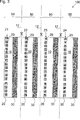
Ein erfindungsgemäßes Ausführungsbeispiel einer Druckform zum Bedrucken eines Trägermaterials mit einem elektrisch leitfähigen Material zum Erzeugen eines erfindungsgemäßen RFID-Bands ist in
Auf der rechten Seite von
Auf der Mantelfläche sind mehrere RFID-Tag-Antennen-Stempelformen
Außerdem sind an der Mantelfläche der Druckform
Zum Bedrucken des Trägermaterials wird die zylinderförmige Druckform
Alternativ kann auch vorgesehen sein, dass die Antennen-Stempelformen
Die RFID-Tag-Antennen-Stempelformen
Zum Erzeugen eines erfindungsgemäßen RFID-Bands reicht grundsätzlich bereits eine Antennen-Stempelform
In dem dargestellten Beispiel sind hingegen vier Antennen-Stempelformen
Jede Reihe
Vorteilhafterweise kann also mit der erfindungsgemäßen Druckform in einfacher Weise ein erfindungsgemäßes RFID-Band erzeugt werden, bei dem ein vorgegebener, insbesondere einheitlicher, Abstand zwischen RFID-Tags und der Antenne zum Kommunizieren mit den RFID-Tags gegeben ist. Indem die RFID-Tags und die Antennen auf demselben Trägermaterial, insbesondere in einem einzigen Arbeitsschritt, erzeugt werden, kann der Herstellungsaufwand vorteilhafterweise reduziert werden. Gegenüber dem Fall, dass eine Antenne nachträglich aufgebracht wird, sind weiterhin vorteilhafterweise weniger Einzelteile zu handhaben.Advantageously, therefore, with the printing form according to the invention, an RFID tape according to the invention can be generated in a simple manner in which a predetermined, in particular uniform, distance between RFID tags and the antenna for communicating with the RFID tags is given. By producing the RFID tags and the antennas on the same carrier material, in particular in a single working step, the production outlay can advantageously be reduced. Compared to the case that an antenna is applied later, advantageously continue to handle fewer items.
ZITATE ENTHALTEN IN DER BESCHREIBUNG QUOTES INCLUDE IN THE DESCRIPTION
Diese Liste der vom Anmelder aufgeführten Dokumente wurde automatisiert erzeugt und ist ausschließlich zur besseren Information des Lesers aufgenommen. Die Liste ist nicht Bestandteil der deutschen Patent- bzw. Gebrauchsmusteranmeldung. Das DPMA übernimmt keinerlei Haftung für etwaige Fehler oder Auslassungen.This list of the documents listed by the applicant has been generated automatically and is included solely for the better information of the reader. The list is not part of the German patent or utility model application. The DPMA assumes no liability for any errors or omissions.
Zitierte PatentliteraturCited patent literature
- DE 202006010232 U1 [0003] DE 202006010232 U1 [0003]
- DE 202006020082 U1 [0003] DE 202006020082 U1 [0003]
- DE 102006004938 A1 [0003] DE 102006004938 A1 [0003]
Claims (15)
Priority Applications (1)
| Application Number | Priority Date | Filing Date | Title |
|---|---|---|---|
| DE201120108076 DE202011108076U1 (en) | 2011-07-22 | 2011-11-18 | RFID tape and printing form for producing an RFID tape |
Applications Claiming Priority (3)
| Application Number | Priority Date | Filing Date | Title |
|---|---|---|---|
| DE202011103626 | 2011-07-22 | ||
| DE202011103626.3 | 2011-07-22 | ||
| DE201120108076 DE202011108076U1 (en) | 2011-07-22 | 2011-11-18 | RFID tape and printing form for producing an RFID tape |
Publications (1)
| Publication Number | Publication Date |
|---|---|
| DE202011108076U1 true DE202011108076U1 (en) | 2011-12-28 |
Family
ID=45528807
Family Applications (1)
| Application Number | Title | Priority Date | Filing Date |
|---|---|---|---|
| DE201120108076 Expired - Lifetime DE202011108076U1 (en) | 2011-07-22 | 2011-11-18 | RFID tape and printing form for producing an RFID tape |
Country Status (1)
| Country | Link |
|---|---|
| DE (1) | DE202011108076U1 (en) |
Citations (3)
| Publication number | Priority date | Publication date | Assignee | Title |
|---|---|---|---|---|
| DE202006010232U1 (en) | 2006-07-01 | 2006-10-05 | Leuze Electronic Gmbh + Co. Kg | Radio frequency identification (RFID) system for parking lights system in vehicles includes transponders and transmitter/receiver unit in which web server is integrated |
| DE102006004938A1 (en) | 2006-02-03 | 2007-08-16 | Leuze Electronic Gmbh + Co. Kg | Positioning system for vehicle, has transmitting and receiving unit, where signals are transmitted from unit to transponders for positioning vehicle at lane limitation, and position of vehicle is transmittable from transponders to unit |
| DE202006020082U1 (en) | 2006-02-03 | 2007-10-11 | Leuze Electronic Gmbh + Co. Kg | positioning |
-
2011
- 2011-11-18 DE DE201120108076 patent/DE202011108076U1/en not_active Expired - Lifetime
Patent Citations (3)
| Publication number | Priority date | Publication date | Assignee | Title |
|---|---|---|---|---|
| DE102006004938A1 (en) | 2006-02-03 | 2007-08-16 | Leuze Electronic Gmbh + Co. Kg | Positioning system for vehicle, has transmitting and receiving unit, where signals are transmitted from unit to transponders for positioning vehicle at lane limitation, and position of vehicle is transmittable from transponders to unit |
| DE202006020082U1 (en) | 2006-02-03 | 2007-10-11 | Leuze Electronic Gmbh + Co. Kg | positioning |
| DE202006010232U1 (en) | 2006-07-01 | 2006-10-05 | Leuze Electronic Gmbh + Co. Kg | Radio frequency identification (RFID) system for parking lights system in vehicles includes transponders and transmitter/receiver unit in which web server is integrated |
Similar Documents
| Publication | Publication Date | Title |
|---|---|---|
| EP0756244B1 (en) | Electronic unit and method of producing that unit | |
| EP1136943B1 (en) | Manufacturing process for transponders | |
| DE60119755T2 (en) | MULTI-BAND, WIRELESS COMMUNICATION DEVICE | |
| DE60014377T2 (en) | INTEGRATED CIRCUIT AND ITS MANUFACTURE, AND INTEGRATED CIRCUIT ASSEMBLED ON AN INFORMATION CARRIER | |
| WO1983004448A1 (en) | Tag-shaped identification device applicable to an object and manufacturing method thereof | |
| WO2015104011A1 (en) | Method and device for machining a substrate | |
| DE102013108255A1 (en) | CHIP CARD MODULE WITH SEPARATE ANTENNA AND CHIP CARD INSERT USING IT | |
| EP3405351B1 (en) | Marking device for marking electrical components | |
| DE202020005420U1 (en) | Processing unit for inserting electronic devices, which are suitable for high-frequency communication, into corresponding rubber sleeves | |
| DE102009023405A1 (en) | Method for producing portable data carriers | |
| DE102016216330A1 (en) | Flexible coil arrangement for a magnetoelectric displacement sensor, displacement sensor and manufacturing method | |
| DE102011114635A1 (en) | Chip card and method for producing a chip card | |
| DE102011106648A1 (en) | Portable data carrier with antenna | |
| DE202011108076U1 (en) | RFID tape and printing form for producing an RFID tape | |
| DE102011118155A1 (en) | Method for producing composite film for inlay used for valuable or security document, involves forming recesses in a compensation film corresponding to component's positions on carrier film and fixing the aligned films in the inlay | |
| EP1889202B1 (en) | Device and method for reading and/or writing data from and/or to a multiplicity of rfid chips | |
| EP2821941B1 (en) | Method for producing a portable data carrier with chip | |
| EP2660607B1 (en) | Identification and localisation of sample containers with RFID tags | |
| EP3236394A2 (en) | Chip card with two coils and ferrite | |
| DE102011080344B4 (en) | PCB with integrated RFID transponder | |
| EP4061643B1 (en) | Method for producing banknotes having at least one integrated circuit | |
| DE10103193B4 (en) | Method for producing printed conductor structures | |
| DE410933C (en) | Loop antenna for wireless telegraphy and telephony | |
| DE102023120087A1 (en) | Coil system for an inductive proximity switch for flush or non-flush installation in a housing | |
| DE102012212996A1 (en) | Method for manufacturing inlay for smart card, involves providing substrate with opening for receiving chip module, while integrated chip is provided to chip module with two contact areas that are spaced apart by encapsulation |
Legal Events
| Date | Code | Title | Description |
|---|---|---|---|
| R207 | Utility model specification |
Effective date: 20120216 |
|
| R150 | Utility model maintained after payment of first maintenance fee after three years | ||
| R150 | Utility model maintained after payment of first maintenance fee after three years |
Effective date: 20141212 |
|
| R151 | Utility model maintained after payment of second maintenance fee after six years | ||
| R082 | Change of representative |
Representative=s name: WUNDERLICH & HEIM PATENTANWAELTE PARTNERSCHAFT, DE |
|
| R081 | Change of applicant/patentee |
Owner name: VERTIV INTEGRATED SYSTEMS GMBH, DE Free format text: FORMER OWNER: KNUERR GMBH, 94424 ARNSTORF, DE |
|
| R082 | Change of representative |
Representative=s name: WUNDERLICH & HEIM PATENTANWAELTE PARTNERSCHAFT, DE |
|
| R158 | Lapse of ip right after 8 years |