DE202011050903U1 - Mixing and dosing device for mixing and dosing of chemicals - Google Patents
Mixing and dosing device for mixing and dosing of chemicals Download PDFInfo
- Publication number
- DE202011050903U1 DE202011050903U1 DE202011050903U DE202011050903U DE202011050903U1 DE 202011050903 U1 DE202011050903 U1 DE 202011050903U1 DE 202011050903 U DE202011050903 U DE 202011050903U DE 202011050903 U DE202011050903 U DE 202011050903U DE 202011050903 U1 DE202011050903 U1 DE 202011050903U1
- Authority
- DE
- Germany
- Prior art keywords
- mixing
- coil
- tube
- metering device
- pitot tube
- Prior art date
- Legal status (The legal status is an assumption and is not a legal conclusion. Google has not performed a legal analysis and makes no representation as to the accuracy of the status listed.)
- Expired - Lifetime
Links
- 239000000126 substance Substances 0.000 title claims abstract description 18
- 238000006243 chemical reaction Methods 0.000 claims abstract description 18
- 239000007788 liquid Substances 0.000 claims abstract description 17
- 239000000463 material Substances 0.000 claims description 11
- 239000003638 chemical reducing agent Substances 0.000 claims description 8
- WYTGDNHDOZPMIW-RCBQFDQVSA-N alstonine Natural products C1=CC2=C3C=CC=CC3=NC2=C2N1C[C@H]1[C@H](C)OC=C(C(=O)OC)[C@H]1C2 WYTGDNHDOZPMIW-RCBQFDQVSA-N 0.000 claims 1
- 239000011541 reaction mixture Substances 0.000 description 4
- 239000012295 chemical reaction liquid Substances 0.000 description 3
- 230000000694 effects Effects 0.000 description 3
- 238000005086 pumping Methods 0.000 description 2
- 230000001914 calming effect Effects 0.000 description 1
- 239000007795 chemical reaction product Substances 0.000 description 1
- 238000011084 recovery Methods 0.000 description 1
- 238000000926 separation method Methods 0.000 description 1
Images


Classifications
-
- B—PERFORMING OPERATIONS; TRANSPORTING
- B01—PHYSICAL OR CHEMICAL PROCESSES OR APPARATUS IN GENERAL
- B01F—MIXING, e.g. DISSOLVING, EMULSIFYING OR DISPERSING
- B01F35/00—Accessories for mixers; Auxiliary operations or auxiliary devices; Parts or details of general application
- B01F35/71—Feed mechanisms
- B01F35/714—Feed mechanisms for feeding predetermined amounts
-
- B—PERFORMING OPERATIONS; TRANSPORTING
- B01—PHYSICAL OR CHEMICAL PROCESSES OR APPARATUS IN GENERAL
- B01J—CHEMICAL OR PHYSICAL PROCESSES, e.g. CATALYSIS OR COLLOID CHEMISTRY; THEIR RELEVANT APPARATUS
- B01J3/00—Processes of utilising sub-atmospheric or super-atmospheric pressure to effect chemical or physical change of matter; Apparatus therefor
- B01J3/006—Processes utilising sub-atmospheric pressure; Apparatus therefor
-
- B—PERFORMING OPERATIONS; TRANSPORTING
- B01—PHYSICAL OR CHEMICAL PROCESSES OR APPARATUS IN GENERAL
- B01F—MIXING, e.g. DISSOLVING, EMULSIFYING OR DISPERSING
- B01F23/00—Mixing according to the phases to be mixed, e.g. dispersing or emulsifying
- B01F23/40—Mixing liquids with liquids; Emulsifying
- B01F23/45—Mixing liquids with liquids; Emulsifying using flow mixing
-
- B—PERFORMING OPERATIONS; TRANSPORTING
- B01—PHYSICAL OR CHEMICAL PROCESSES OR APPARATUS IN GENERAL
- B01F—MIXING, e.g. DISSOLVING, EMULSIFYING OR DISPERSING
- B01F25/00—Flow mixers; Mixers for falling materials, e.g. solid particles
- B01F25/40—Static mixers
- B01F25/42—Static mixers in which the mixing is affected by moving the components jointly in changing directions, e.g. in tubes provided with baffles or obstructions
- B01F25/43—Mixing tubes, e.g. wherein the material is moved in a radial or partly reversed direction
- B01F25/433—Mixing tubes wherein the shape of the tube influences the mixing, e.g. mixing tubes with varying cross-section or provided with inwardly extending profiles
- B01F25/4331—Mixers with bended, curved, coiled, wounded mixing tubes or comprising elements for bending the flow
-
- B—PERFORMING OPERATIONS; TRANSPORTING
- B01—PHYSICAL OR CHEMICAL PROCESSES OR APPARATUS IN GENERAL
- B01F—MIXING, e.g. DISSOLVING, EMULSIFYING OR DISPERSING
- B01F25/00—Flow mixers; Mixers for falling materials, e.g. solid particles
- B01F25/50—Circulation mixers, e.g. wherein at least part of the mixture is discharged from and reintroduced into a receptacle
- B01F25/51—Circulation mixers, e.g. wherein at least part of the mixture is discharged from and reintroduced into a receptacle in which the mixture is circulated through a set of tubes, e.g. with gradual introduction of a component into the circulating flow
-
- B—PERFORMING OPERATIONS; TRANSPORTING
- B01—PHYSICAL OR CHEMICAL PROCESSES OR APPARATUS IN GENERAL
- B01F—MIXING, e.g. DISSOLVING, EMULSIFYING OR DISPERSING
- B01F35/00—Accessories for mixers; Auxiliary operations or auxiliary devices; Parts or details of general application
- B01F35/71—Feed mechanisms
- B01F35/717—Feed mechanisms characterised by the means for feeding the components to the mixer
- B01F35/7176—Feed mechanisms characterised by the means for feeding the components to the mixer using pumps
-
- B—PERFORMING OPERATIONS; TRANSPORTING
- B01—PHYSICAL OR CHEMICAL PROCESSES OR APPARATUS IN GENERAL
- B01J—CHEMICAL OR PHYSICAL PROCESSES, e.g. CATALYSIS OR COLLOID CHEMISTRY; THEIR RELEVANT APPARATUS
- B01J3/00—Processes of utilising sub-atmospheric or super-atmospheric pressure to effect chemical or physical change of matter; Apparatus therefor
- B01J3/02—Feed or outlet devices therefor
-
- B—PERFORMING OPERATIONS; TRANSPORTING
- B01—PHYSICAL OR CHEMICAL PROCESSES OR APPARATUS IN GENERAL
- B01J—CHEMICAL OR PHYSICAL PROCESSES, e.g. CATALYSIS OR COLLOID CHEMISTRY; THEIR RELEVANT APPARATUS
- B01J3/00—Processes of utilising sub-atmospheric or super-atmospheric pressure to effect chemical or physical change of matter; Apparatus therefor
- B01J3/04—Pressure vessels, e.g. autoclaves
- B01J3/044—Pressure vessels, e.g. autoclaves in the form of a loop
-
- B—PERFORMING OPERATIONS; TRANSPORTING
- B01—PHYSICAL OR CHEMICAL PROCESSES OR APPARATUS IN GENERAL
- B01F—MIXING, e.g. DISSOLVING, EMULSIFYING OR DISPERSING
- B01F35/00—Accessories for mixers; Auxiliary operations or auxiliary devices; Parts or details of general application
- B01F35/75—Discharge mechanisms
- B01F35/754—Discharge mechanisms characterised by the means for discharging the components from the mixer
- B01F35/75465—Discharge mechanisms characterised by the means for discharging the components from the mixer using suction, vacuum, e.g. with a pipette
Landscapes
- Chemical & Material Sciences (AREA)
- Chemical Kinetics & Catalysis (AREA)
- Organic Chemistry (AREA)
- Dispersion Chemistry (AREA)
- Feeding, Discharge, Calcimining, Fusing, And Gas-Generation Devices (AREA)
- Physical Or Chemical Processes And Apparatus (AREA)
- Sampling And Sample Adjustment (AREA)
Abstract
Misch- und Dosiervorrichtung zum Mischen und Dosieren von flüssigen Chemikalien umfassend:
eine Kreislaufpumpe (2) mit einem Saugstutzen und einem Druckstutzen,
eine Rohrschlange (12), deren Volumeninhalt so bemessen ist, dass die in die Vorrichtung eindosierten Chemikalien eine für die chemische Umsetzung ausreichende Verweilzeit haben,
ein Staurohr (18), das den aus der Rohrschlange (12) austretenden Kreislaufstrom unter Bildung einer Staustelle von dem Auslass der Rohrschlage zu einer Dosierleitung (40) führt, die zwischen dem Staurohr (18) und dem Saugstutzen der Kreislaufpumpe (2) angeordnet ist und wenigsten zwei Dosierventile (50, 52) umfasst, sowie
ein Fallrohr (28), das mit dem Staurohr (18) verbunden ist und einen Vakuumflansch (36) zum Anschluss der Misch- und Dosiervorrichtung an eine Vakuumvorrichtung aufweist.Mixing and dosing device for mixing and dosing liquid chemicals comprising:
a circulation pump (2) with a suction nozzle and a discharge nozzle,
a tube coil (12) whose volume content is such that the chemicals metered into the device have a residence time sufficient for the chemical reaction,
a Pitot tube (18), which leads from the tube coil (12) emerging circulatory stream to form a surge point from the outlet of the tube impact to a metering line (40) which is arranged between the pitot tube (18) and the suction nozzle of the circulation pump (2) and at least two metering valves (50, 52), and
a drop tube (28) connected to the pitot tube (18) and having a vacuum flange (36) for connecting the mixing and metering device to a vacuum device.

Description
Die Erfindung betrifft Vorrichtung zum Mischen und Dosieren von flüssigen Chemikalien sowie Gewinnung eines flüssigen Reaktionsgutes unter Vakuumbedingungen.The invention relates to apparatus for mixing and dosing of liquid chemicals and recovery of a liquid reaction material under vacuum conditions.
Der Erfindung liegt die Aufgabe zugrunde, eine Misch- und Dosiervorrichtung zum Mischen und Dosieren von Chemikalien unter Vakuumbedingungen anzugeben, die auch unter nichtstationären Bedingungen und insbesondere unter Neigung und Bewegung den Misch- und Dosiervorgang sicher und befriedigend durchführen kann.The invention has for its object to provide a mixing and metering device for mixing and dosing of chemicals under vacuum conditions, which can perform safely and satisfactorily under non-stationary conditions and in particular under inclination and movement the mixing and dosing.
Dazu wird eine Misch- und Dosiervorrichtung zum Mischen und Dosieren von flüssigen Chemikalien angegeben, die umfasst eine Kreislaufpumpe mit einem Saugstutzen und einem Druckstutzen, eine Rohrschlange, deren Volumeninhalt so bemessen ist, dass die in die Vorrichtung eindosierten Chemikalien eine für die chemische Umsetzung ausreichende Verweilzeit haben, ein Staurohr, das den aus der Rohrschlange austretenden Kreislaufstrom unter Bildung einer Staustelle von dem Auslass der Rohrschlage zu einer Dosierleitung führt, die zwischen dem Staurohr und dem Saugstutzen der Kreislaufpumpe angeordnet ist und wenigsten zwei Dosierventile umfasst, sowie ein Fallrohr, das mit dem Staurohr verbunden ist und einen Vakuumflansch zum Anschluss der Misch- und Dosiervorrichtung an eine Vakuumvorrichtung aufweist. In der erfindungsgemäßen Misch- und Dosiervorrichtung werden die Chemikalien in einen Kreislaufstrom eindosierten, dessen Volumeninhalt so bemessen ist, dass die eindosierten Chemikalien eine für die chemische Umsetzung ausreichende Verweilzeit haben, dass der Kreislaufstrom an einer Staustelle aufgestaut wird, und ein Reaktionsgutstrom aus flüssigem Reaktionsgut wird an der Staustelle aus dem Kreislaufstrom durch Vakuum abgesaugt. Die erfindungsgemäße Vorrichtung vermag die Aufgabe, das Mischen und Dosieren von Chemikalien unter Vakuum auch unter nichtstationären Bedingungen und insbesondere unter Neigung und Bewegung durchzuführen.For this purpose, a mixing and metering device for mixing and dosing of liquid chemicals is specified, which comprises a circulation pump with a suction nozzle and a discharge nozzle, a coil whose volume content is such that the metered into the device chemicals sufficient for the chemical reaction residence time have a pitot tube, which discharges the circulating flow emerging from the tube to form a jam point from the outlet of the tube whip to a metering, which is arranged between the pitot tube and the suction nozzle of the circulation pump and comprises at least two metering valves, and a downpipe, with the Pitot tube is connected and has a vacuum flange for connection of the mixing and metering device to a vacuum device. In the mixing and metering device according to the invention, the chemicals are metered into a circulation stream whose volume content is such that the metered chemicals have sufficient residence time for the chemical reaction, that the circulation stream is dammed at a jam site, and a Reaktionsgutstrom of liquid reaction material is sucked out of the circulation stream by vacuum at the storage site. The device of the invention is capable of performing the mixing and dosing of chemicals under vacuum even under non-stationary conditions and in particular under inclination and movement.
Eine bevorzugte Ausführungsform der der erfindungsgemäßen Misch- und Dosiervorrichtung ist dadurch gekennzeichnet, dass die Rohrschlange aufrecht stehend angeordnet ist und unten einen Einlauf und oben einen Auslauf hat, dass das Staurohr den aus der Rohrschlange austretenden Kreislaufstrom von dem Auslass der Rohrschlage nach unten zu der Dosierleitung führt, die horizontalen zwischen dem Staurohr und dem Saugstutzen der Kreislaufpumpe angeordnet ist, und dass das Fallrohr mit einem oberen oberhalb des Niveaus der Rohrschlange liegenden Ende des Staurohres verbunden ist und am unteren Ende einen Vakuumflansch zum Anschluss der Misch- und Dosiervorrichtung an eine Vakuumvorrichtung aufweist. Durch die aufrechtstehende Anordnung der Rohrschlange und die räumliche Anordnung des Staurohres und des Fallrohres gegenüber der Rohrschlange wird die erfindungsgemäße Vorrichtung in vorteilhafter Weise noch weniger in sich gegen Lageänderungen bei nicht stationärem Betrieb eine Neigung oder eine Bewegung der Vorrichtung beispielsweise, wenn diese auf einem Fahrzeug montiert ist.A preferred embodiment of the mixing and metering device according to the invention is characterized in that the coil is arranged upright and below an inlet and above an outlet that the pitot tube exiting the coil from the loop flow from the outlet of the tube blows down to the dosing leads, which is arranged horizontally between the pitot tube and the suction nozzle of the circulation pump, and that the drop tube is connected to an upper above the level of the tube coil end of the pitot tube and at the bottom of a vacuum flange for connecting the mixing and metering device to a vacuum device , Due to the upright arrangement of the pipe coil and the spatial arrangement of the pitot tube and the downpipe against the coil, the device according to the invention is advantageously less in itself against changes in position during non-stationary operation, a tendency or movement of the device, for example, when mounted on a vehicle is.
Eine weitere bevorzugte Ausführungsform der der erfindungsgemäßen Misch- und Dosiervorrichtung ist dadurch gekennzeichnet, dass die Dosierventile stopfbuchsenlos und in Form von Faltenbalgventilen ausgeführt sind. Derartige Dosierventile eignen sich besonders gut für die Regelung von flüssigen Chemikalien.Another preferred embodiment of the mixing and metering device according to the invention is characterized in that the metering valves are glandless and designed in the form of Faltenbalgventilen. Such metering valves are particularly well suited for the control of liquid chemicals.
Eine weitere bevorzugte Ausführungsform der der erfindungsgemäßen Misch- und Dosiervorrichtung ist dadurch gekennzeichnet, dass die Kreislaufpumpe eine Kreiselpumpe ist, wodurch eine effektive und für die Chemikalien schonende Förderleistung der Pumpe sichergestellt wird.A further preferred embodiment of the mixing and metering device according to the invention is characterized in that the circulation pump is a centrifugal pump, whereby an effective and gentle for the chemicals delivery capacity of the pump is ensured.
Eine weitere bevorzugte Ausführungsform der der erfindungsgemäßen Misch- und Dosiervorrichtung ist dadurch gekennzeichnet, dass die Rohrschlange mäanderartig als aufrecht stehende Flachrohrschlange ausgeführt ist, wobei der Platzbedarf der Rohrschlange herab gesetzt wird, ohne dass die Rohrschlange in ihrem Volumen kleiner gemacht wird.A further preferred embodiment of the mixing and metering device according to the invention is characterized in that the tube meander is designed as an upright flat tube coil, the space requirement of the coil is set down without the tube coil is made smaller in volume.
Eine weitere bevorzugte Ausführungsform der der erfindungsgemäßen Misch- und Dosiervorrichtung ist dadurch gekennzeichnet, dass das Staurohr mit einem Abflussflansch der Rohrschlange über einen Flanschstutzen an einem T-Stück verbunden ist, das in das der Kreislaufstrom derart eingeführt wird, dass er in dem T-Stück in seiner Bewegungsrichtung umgelenkt wird. Bei dieser Anordnung des T-Stücks als Staustelle trifft der aus der Rohrschlange austretende Kreislaufstrom direkt auf eine geschlossene Rückwand des T-Stücks, so dass dadurch und durch die Umlenkung des Kreislaufstroms in dem T-Stück eine Stauwirkung erzielt wird. Dieser Stauwirkung kann in vorteilhafter Weise dazu benutzt werden, flüssiges Reaktionsgut aus dem Kreislaufstrom abzuziehen mit Hilfe eines Vakuums, das am Ausgang der Vorrichtung ansteht.A further preferred embodiment of the mixing and metering device according to the invention is characterized in that the pitot tube is connected to a drain flange of the coil via a flange on a T-piece, in which the circulating flow is introduced so that it in the T-piece is deflected in its direction of movement. With this arrangement of the T-piece as a jam point, the circulating stream emerging from the pipe coil strikes directly on a closed rear wall of the T-piece, so that a congestion effect is achieved thereby and by the deflection of the circulation flow in the T-piece. This congestion effect can be used advantageously to draw liquid reaction material from the circulation stream by means of a vacuum which is present at the outlet of the device.
Eine weitere bevorzugte Ausführungsform der der erfindungsgemäßen Misch- und Dosiervorrichtung ist dadurch gekennzeichnet, dass oben an das T-Stück ein Rohr-Reduzierstück angeschlossen ist, wobei der Strom des Reaktionsgutes in Strömungsrichtung nach der Staustelle in Bezug auf Turbulenzen beruhigt wird. A further preferred embodiment of the mixing and metering device according to the invention is characterized in that a pipe reducer is connected to the top of the T-piece, wherein the flow of the reaction material is calmed in the flow direction to the stowage point with respect to turbulence.
Eine weitere bevorzugte Ausführungsform der der erfindungsgemäßen Misch- und Dosiervorrichtung ist dadurch gekennzeichnet, dass an das T-Stück ein Steigrohr angeschlossen ist, durch das das Staurohr über das Niveau der Rohrschlange hinaus verlängert ist, wodurch in vorteilhafter Weise eine weitere Beruhigung des Reaktionsgutstromes erreicht wird.A further preferred embodiment of the mixing and metering device according to the invention is characterized in that a riser is connected to the T-piece, through which the pitot tube is extended beyond the level of the coil out, whereby a further calming of the Reaktionsgutstromes is achieved in an advantageous manner ,
Eine weitere bevorzugte Ausführungsform der erfindungsgemäßen Misch- und Dosiervorrichtung ist dadurch gekennzeichnet, dass Durchmesser des Fallrohres geringer ist als der Durchmesser des Staurohres, wobei insbesondere der Innendurchmesser des Staurohres, der Rohrleitungen (außer dem Fallrohre) sowie der Innendurchmesser der Rohrschlange so gewaehlt ist, dass bei vorgegebener Pumpleistung der Kreislaufpumpe und vorgegebener dynamischer Viskosität des Reaktionsgutes die Reynolds-Zahl > 2300 ist, und dass der Innendurchmesser des Fallrohres so weit ist, dass die Filmdicke des an der Innenseite des Fallrohres herabfließenden Reaktionsgutes ein Bruchteil des Innendurchmessers des Fallrohres ist. Dadurch wird in vorteilhafter Weise der Tatsache Rechnung getragen, dass einerseits in der Rohrschlange und dem Staurohr eine ausreichend starke Strömung fließen sollte, während in dem Fallrohr nur ein Flüssigkeitsfilm aus dem Reaktionsgut an den Wänden herunter rieseln sollte.A further preferred embodiment of the mixing and metering device according to the invention is characterized in that the diameter of the drop tube is smaller than the diameter of the pitot tube, wherein in particular the inner diameter of the pitot tube, the pipes (except the downpipes) and the inner diameter of the coil is chosen so that at a given pumping capacity of the circulation pump and given dynamic viscosity of the reaction material, the Reynolds number is> 2300, and that the inner diameter of the downpipe is so far that the film thickness of the flowing down on the inside of the downcomer reaction material is a fraction of the inner diameter of the downpipe. This advantageously takes into account the fact that, on the one hand, a sufficiently strong flow should flow in the pipe coil and the pitot tube, while only one liquid film from the reaction mixture should trickle down the walls in the downpipe.
Eine weitere bevorzugte Ausführungsform der erfindungsgemäßen Misch- und Dosiervorrichtung ist dadurch gekennzeichnet, dass die hydraulische Verbindung zwischen dem Fallrohr und dem Steigrohr eine Transferleitung aufweist. Damit kann in vorteilhafter Weise erreicht werden, dass die Reaktionsgutflüssigkeit in der Transferleitung nicht den gesamten Querschnitt der Leitung einnimmt, dass das in dem Fallrohr vorhandene Vakuum auch in der Transferleitung wirksam werden kann.A further preferred embodiment of the mixing and metering device according to the invention is characterized in that the hydraulic connection between the downpipe and the riser pipe has a transfer line. This can be achieved in an advantageous manner that the reaction liquid does not occupy the entire cross section of the line in the transfer line, that the present in the downpipe vacuum can also be effective in the transfer line.
Eine weitere bevorzugte Ausführungsform der erfindungsgemäßen Misch- und Dosiervorrichtung ist dadurch gekennzeichnet, dass die Transferleitung höhenmäßig oberhalb des obersten Rohres der Rohrschlange angeordnet ist, wobei das Reaktionsgut von der Staustelle nach oben und über das Fallrohr nach unten geführt wird, in dem ein Vakuum erzeugt wird. Damit wird zusätzlich sichergestellt, dass, wenn die Vorrichtung in Betrieb Schwankungen und Lageänderungen unterworfen ist, der Betrieb in der Rohrschlange nicht beeinträchtigt wird, da das Flüssigkeitsniveau in der Rohrschlange immer niedriger ist als in der Transferleitung.A further preferred embodiment of the mixing and metering device according to the invention is characterized in that the transfer line is arranged in height above the uppermost tube of the tube, wherein the reaction mixture is guided from the storage point upwards and down the downpipe, in which a vacuum is generated , This additionally ensures that, when the device is subjected to fluctuations in operation and changes in position, the operation in the coil is not affected, since the liquid level in the coil is always lower than in the transfer line.
Eine weitere bevorzugte Ausführungsform der erfindungsgemäßen Misch- und Dosiervorrichtung ist dadurch gekennzeichnet, dass eine Entleerungsleitung mit einem Entleerungsventil zwischen dem Saugstutzen der Kreislaufpumpe und dem Fallrohr vorgesehen ist. Dadurch kann die Vorrichtung auf einfache Weise nach Betriebsstilllegung entleert werden, um Nachteile der Nachwirkungen der Chemikalien zu vermeiden.A further preferred embodiment of the mixing and metering device according to the invention is characterized in that a drain line is provided with a drain valve between the suction port of the circulation pump and the downpipe. As a result, the device can be emptied in a simple manner after shutdown in order to avoid disadvantages of the after-effects of the chemicals.
Weitere Vorteile, Merkmale und Anwendungsmöglichkeiten der vorliegenden Erfindung ergeben sich aus der nachfolgenden Beschreibung in Verbindung mit den in den Zeichnungen dargestellten Ausführungsbeispielen.Further advantages, features and possible applications of the present invention will become apparent from the following description in conjunction with the embodiments illustrated in the drawings.
In der Beschreibung, in den Ansprüchen und in der Zeichnung werden die in der unten aufgeführten Liste der Bezugzeichen verwendeten Begriffe und zugeordneten Bezugzeichen verwendet. In der Zeichnung bedeutet:In the specification, claims, and drawings, the terms and associated reference numerals used in the list of reference numerals below are used. In the drawing:
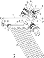
Die erfindungsgemäße Vorrichtung nach
Die erfindungsgemäße Vorrichtung weist eine Rohrschlange
Der durch die Misch- und Zirkulationspumpe
Die erfindungsgemäße Vorrichtung weist ein Staurohr
Die erfindungsgemäße Vorrichtung weist ein Fallrohr
Wie aus
Wie aus
An die Rohrabzweigungen der T-Stücke
Wie aus
Der Kreislaufstrom der Reaktionsflüssigkeit fließt aus der Rohrschlange
Der Innendurchmesser dRohr des Staurohres, der Rohrleitungen
Der Innendurchmesser diF (m) des Fallrohres
Die erfindungsgemäße Vorrichtung weist auch eine Entleerungsleitung
Während des Dosierbetriebes ist das Absperrventil
BezugszeichenlisteLIST OF REFERENCE NUMBERS
- 22
- Zirkulationspumpecirculation pump
- 44
- Saugstutzensuction
- 66
- Saugflanschsuction flange
- 88th
- Druckstutzenpressure port
- 1010
- Druckflanschpressure flange
- 1212
- ebene Rohrschlangeflat pipe coil
- 1414
- Einlaufflanschinlet flange
- 1616
- AbflussflanschAbflussflansch
- 1818
- StaurohrPitot tube
- 2020
- Verbindungsflanschconnecting flange
- 2222
- T-StückTee
- 2424
- Rohr-ReduzierstückPipe Reducer
- 2626
- Steigrohrriser
- 2828
- Fallrohrdownspout
- 3030
- Transferleitungtransfer line
- 3232
- Flansch TransferleitungFlange transfer line
- 3434
- Flansch SteigrohrFlange riser
- 3636
- Vakuumflanschvacuum flange
- 3838
- RohrbogenElbows
- 4040
- Obere DosierleitungUpper dosing line
- 4242
- T-Stück verringerte AbzweigungTee reduced turnoff
- 4444
- T-Stück verringerte AbzweigungTee reduced turnoff
- 4646
- konisches Reduzierstückconical reducer
- 4848
- konisches Reduzierstückconical reducer
- 5050
- Dosierventilmetering valve
- 5252
- Dosierventilmetering valve
- 5454
- RohrbogenElbows
- 5656
- Verbindungsleitungconnecting line
- 5858
- RohrbogenElbows
- 6060
- Untere DosierleitungLower dosing line
- 6262
- Rohrbogen DosierleitungPipe bend Dosing line
- 6464
- DosierflanschDosierflansch
- 6666
- Entleerungsleitungdrain line
- 6868
- T-Stück verringerte AbzweigungTee reduced turnoff
- 7070
- Rohrbogen EntleerungsleitungPipe bend emptying pipe
- 7272
- Entleerungsventildrain valve
- 7474
- Flansch EntleerungsleitungFlange drainage pipe
- 7676
- Flansch am T-StückFlange on the tee
- 7878
- T-StückTee
Claims (13)
Priority Applications (7)
| Application Number | Priority Date | Filing Date | Title |
|---|---|---|---|
| DE202011050903U DE202011050903U1 (en) | 2011-08-04 | 2011-08-04 | Mixing and dosing device for mixing and dosing of chemicals |
| PCT/EP2012/065245 WO2013017685A1 (en) | 2011-08-04 | 2012-08-03 | Mixing and metering device for mixing and metering chemicals |
| CN201280038580.2A CN103747857B (en) | 2011-08-04 | 2012-08-03 | Mixing and metering devices for mixing and metering chemical substances |
| US14/236,898 US9162197B2 (en) | 2011-08-04 | 2012-08-03 | Mixing and metering device for mixing and metering chemicals |
| BR112014002685-8A BR112014002685B1 (en) | 2011-08-04 | 2012-08-03 | MIXING AND MEASUREMENT DEVICE FOR MIXING AND MEASURING CHEMICALS |
| EP12748409.5A EP2739380B1 (en) | 2011-08-04 | 2012-08-03 | Mixing and metering device for mixing and metering chemicals |
| ES12748409.5T ES2560254T3 (en) | 2011-08-04 | 2012-08-03 | Mixing and dosing device for mixing and dosing chemicals |
Applications Claiming Priority (1)
| Application Number | Priority Date | Filing Date | Title |
|---|---|---|---|
| DE202011050903U DE202011050903U1 (en) | 2011-08-04 | 2011-08-04 | Mixing and dosing device for mixing and dosing of chemicals |
Publications (1)
| Publication Number | Publication Date |
|---|---|
| DE202011050903U1 true DE202011050903U1 (en) | 2011-10-11 |
Family
ID=44925065
Family Applications (1)
| Application Number | Title | Priority Date | Filing Date |
|---|---|---|---|
| DE202011050903U Expired - Lifetime DE202011050903U1 (en) | 2011-08-04 | 2011-08-04 | Mixing and dosing device for mixing and dosing of chemicals |
Country Status (7)
| Country | Link |
|---|---|
| US (1) | US9162197B2 (en) |
| EP (1) | EP2739380B1 (en) |
| CN (1) | CN103747857B (en) |
| BR (1) | BR112014002685B1 (en) |
| DE (1) | DE202011050903U1 (en) |
| ES (1) | ES2560254T3 (en) |
| WO (1) | WO2013017685A1 (en) |
Cited By (3)
| Publication number | Priority date | Publication date | Assignee | Title |
|---|---|---|---|---|
| WO2017081242A1 (en) | 2015-11-11 | 2017-05-18 | Holger Blum | Metering device |
| DE202018106088U1 (en) | 2018-10-24 | 2018-11-16 | Anni Hjorth Blum | Mixing and dosing device for mixing and dosing of liquid chemicals |
| EP3241603A4 (en) * | 2014-12-29 | 2019-02-13 | Wakana Kaizuka | Mixing-dispersing method and device |
Families Citing this family (4)
| Publication number | Priority date | Publication date | Assignee | Title |
|---|---|---|---|---|
| DE202011050903U1 (en) * | 2011-08-04 | 2011-10-11 | Holger Blum | Mixing and dosing device for mixing and dosing of chemicals |
| EP3339405A1 (en) | 2016-12-20 | 2018-06-27 | Alfa Laval Corporate AB | Separation of contaminants from a liquid mixture |
| CN107998911A (en) * | 2018-01-19 | 2018-05-08 | 南通永大管业股份有限公司 | A kind of closed corrosivity powder curved tube agitating device |
| CN113117546A (en) * | 2021-05-25 | 2021-07-16 | 北京林业大学 | Pipeline mixer and medicine mixing device |
Family Cites Families (14)
| Publication number | Priority date | Publication date | Assignee | Title |
|---|---|---|---|---|
| US2382871A (en) * | 1943-04-21 | 1945-08-14 | Universal Oil Prod Co | Method of mixing fluids |
| US3486862A (en) * | 1964-09-19 | 1969-12-30 | Basf Ag | Apparatus for the continuous production of a foamed resin |
| FR2383887A1 (en) * | 1977-03-18 | 1978-10-13 | Bono Pierre | Installation to purify waste water in continuous flow - through passage into which reagents are injected upstream of static mixers |
| ES2159439T3 (en) | 1997-07-24 | 2001-10-01 | Siemens Axiva Gmbh & Co Kg | MIXER, HEAT EXCHANGER AND CONTINUOUS CAOTIC CONVECTION REACTOR. |
| DE102006026254A1 (en) | 2006-06-02 | 2007-12-06 | Schmidt & Heinzmann Gmbh & Co. Kg | Mixing equipment for molding compound used to produce polymer sheet for further processing, is designed with recirculating pumping line |
| EP2133141A1 (en) * | 2008-06-10 | 2009-12-16 | Nederlandse Organisatie voor Toegepast-Natuuurwetenschappelijk Onderzoek TNO | Process for carrying out multi-phase reactions |
| JP4667539B2 (en) * | 2008-08-07 | 2011-04-13 | 旭有機材工業株式会社 | Fluid mixer and device using fluid mixer |
| KR101263395B1 (en) * | 2008-10-20 | 2013-05-10 | 아사히 유키자이 고교 가부시키가이샤 | Helical fluid mixer and device using helical fluid mixer |
| JP5484008B2 (en) * | 2009-11-13 | 2014-05-07 | 旭有機材工業株式会社 | Static fluid mixer and apparatus using static fluid mixer |
| EP2336093A1 (en) | 2009-12-14 | 2011-06-22 | Arkema Vlissingen B.V. | Process for scratch masking of glass containers |
| JP5441746B2 (en) * | 2010-02-05 | 2014-03-12 | 旭有機材工業株式会社 | Fluid mixer and device using fluid mixer |
| CN201644042U (en) | 2010-02-08 | 2010-11-24 | 薛守举 | Low-temperature plasma micro-emulsifying machine |
| DE202011050903U1 (en) * | 2011-08-04 | 2011-10-11 | Holger Blum | Mixing and dosing device for mixing and dosing of chemicals |
| DE102012006049A1 (en) * | 2012-03-27 | 2013-10-02 | Heinrich Quarder | Static mixer has input-sided admixing device, downstream mixing device for mixing two or multiple fluid components with different specific gravities, and vertical strands, in which mixing elements are arranged, which passes through mixture |
-
2011
- 2011-08-04 DE DE202011050903U patent/DE202011050903U1/en not_active Expired - Lifetime
-
2012
- 2012-08-03 US US14/236,898 patent/US9162197B2/en not_active Expired - Fee Related
- 2012-08-03 ES ES12748409.5T patent/ES2560254T3/en active Active
- 2012-08-03 EP EP12748409.5A patent/EP2739380B1/en not_active Not-in-force
- 2012-08-03 CN CN201280038580.2A patent/CN103747857B/en not_active Expired - Fee Related
- 2012-08-03 BR BR112014002685-8A patent/BR112014002685B1/en not_active IP Right Cessation
- 2012-08-03 WO PCT/EP2012/065245 patent/WO2013017685A1/en not_active Ceased
Cited By (4)
| Publication number | Priority date | Publication date | Assignee | Title |
|---|---|---|---|---|
| EP3241603A4 (en) * | 2014-12-29 | 2019-02-13 | Wakana Kaizuka | Mixing-dispersing method and device |
| WO2017081242A1 (en) | 2015-11-11 | 2017-05-18 | Holger Blum | Metering device |
| DE202018106088U1 (en) | 2018-10-24 | 2018-11-16 | Anni Hjorth Blum | Mixing and dosing device for mixing and dosing of liquid chemicals |
| WO2020084077A1 (en) * | 2018-10-24 | 2020-04-30 | Hjorth Blum, Anni | Mixing and metering device for mixing and metering liquid chemicals |
Also Published As
| Publication number | Publication date |
|---|---|
| CN103747857B (en) | 2015-11-25 |
| US9162197B2 (en) | 2015-10-20 |
| BR112014002685A2 (en) | 2017-06-13 |
| EP2739380B1 (en) | 2015-10-21 |
| WO2013017685A1 (en) | 2013-02-07 |
| ES2560254T3 (en) | 2016-02-18 |
| EP2739380A1 (en) | 2014-06-11 |
| US20140219047A1 (en) | 2014-08-07 |
| CN103747857A (en) | 2014-04-23 |
| BR112014002685A8 (en) | 2017-06-20 |
| BR112014002685B1 (en) | 2020-08-11 |
Similar Documents
| Publication | Publication Date | Title |
|---|---|---|
| EP2739380B1 (en) | Mixing and metering device for mixing and metering chemicals | |
| DE60204646T2 (en) | Vacuum-assisted drainage system and process for handling cutting or lubricating fluids of machine tools | |
| EP2777794B1 (en) | Filter cartridge and filter device | |
| CH655249A5 (en) | DEVICE FOR DEGASSING A LIQUID CIRCUIT. | |
| DE60011283T2 (en) | DEVICE FOR LUBRICATING SOLIDS FROM SLUDGE | |
| DE202010014799U1 (en) | mixing device | |
| EP0022186B1 (en) | Apparatus for liquid-liquid extraction | |
| DE1667242B2 (en) | Device for contacting a gas with a liquid | |
| DE202008006552U1 (en) | Water supply system | |
| DE102010055452A1 (en) | Flow guide device for use in manhole of sloping fluid channel of fluid distributor for wound heat exchanger for guiding fluid flow, has flow breaker dividing fluid flow into fluid flows so that fluid flows unblock passage opening for gas | |
| EP3159315B1 (en) | Device and method for gas injection in a sludge tank for sludge circulation | |
| DE102008018998A1 (en) | Device for conducting water from reservoir to fluidic turbines in water power plant, has fluidic turbines arranged adjacent to each other, where each turbine is in lower region of turbine-down pipe and length of pipes is equally large | |
| DE102004044586A1 (en) | Device for controlling the temperature of bulk material | |
| DE202014105468U1 (en) | Oil-water separation structure and oil-water separation system with just this separation structure | |
| DE102021114804B3 (en) | Outlet for beverage preparation machine | |
| DE202008004126U1 (en) | Mixing device for air and water to form fine bubbles | |
| DE202018106088U1 (en) | Mixing and dosing device for mixing and dosing of liquid chemicals | |
| DE1609052A1 (en) | Line disconnection device, especially for electrical household appliances, such as washing machines, dishwashers and the like. | |
| EP2072823A2 (en) | Rotary pump with venting arrangement | |
| EP2770215A1 (en) | Pump device, and diffuser for a pump device | |
| DE102008010360A1 (en) | pump means | |
| DE19960893A1 (en) | Device for regulating delivery of circulating pumps includes deflection plate in part of inflow cross-section above sluice to divert fluid in opposite direction in event of full flow | |
| EP2952482A1 (en) | Device for the treatment of water in a body of water | |
| EP3150771A1 (en) | Waste water tank with a drain mechanism | |
| DE102012024814A1 (en) | Cooling water outlet system |
Legal Events
| Date | Code | Title | Description |
|---|---|---|---|
| R207 | Utility model specification |
Effective date: 20111201 |
|
| R150 | Utility model maintained after payment of first maintenance fee after three years | ||
| R150 | Utility model maintained after payment of first maintenance fee after three years |
Effective date: 20141022 |
|
| R151 | Utility model maintained after payment of second maintenance fee after six years | ||
| R152 | Utility model maintained after payment of third maintenance fee after eight years | ||
| R071 | Expiry of right |