DE202010000710U1 - solar panel - Google Patents
solar panel Download PDFInfo
- Publication number
- DE202010000710U1 DE202010000710U1 DE202010000710U DE202010000710U DE202010000710U1 DE 202010000710 U1 DE202010000710 U1 DE 202010000710U1 DE 202010000710 U DE202010000710 U DE 202010000710U DE 202010000710 U DE202010000710 U DE 202010000710U DE 202010000710 U1 DE202010000710 U1 DE 202010000710U1
- Authority
- DE
- Germany
- Prior art keywords
- diode
- solar panel
- solar
- electrical
- cover element
- Prior art date
- Legal status (The legal status is an assumption and is not a legal conclusion. Google has not performed a legal analysis and makes no representation as to the accuracy of the status listed.)
- Expired - Lifetime
Links
- 239000004020 conductor Substances 0.000 claims abstract description 67
- 230000001070 adhesive effect Effects 0.000 claims description 16
- 229920003002 synthetic resin Polymers 0.000 claims description 16
- 239000000057 synthetic resin Substances 0.000 claims description 16
- 239000000853 adhesive Substances 0.000 claims description 15
- 229920005989 resin Polymers 0.000 description 8
- 239000011347 resin Substances 0.000 description 8
- 238000005476 soldering Methods 0.000 description 6
- 238000000034 method Methods 0.000 description 4
- 229910000679 solder Inorganic materials 0.000 description 4
- 239000000463 material Substances 0.000 description 3
- 238000007789 sealing Methods 0.000 description 3
- 238000004026 adhesive bonding Methods 0.000 description 2
- 230000000694 effects Effects 0.000 description 2
- 239000011521 glass Substances 0.000 description 2
- 238000009434 installation Methods 0.000 description 2
- 239000007788 liquid Substances 0.000 description 2
- 238000004519 manufacturing process Methods 0.000 description 2
- 239000002184 metal Substances 0.000 description 2
- 229910052751 metal Inorganic materials 0.000 description 2
- 238000003466 welding Methods 0.000 description 2
- BUHVIAUBTBOHAG-FOYDDCNASA-N (2r,3r,4s,5r)-2-[6-[[2-(3,5-dimethoxyphenyl)-2-(2-methylphenyl)ethyl]amino]purin-9-yl]-5-(hydroxymethyl)oxolane-3,4-diol Chemical compound COC1=CC(OC)=CC(C(CNC=2C=3N=CN(C=3N=CN=2)[C@H]2[C@@H]([C@H](O)[C@@H](CO)O2)O)C=2C(=CC=CC=2)C)=C1 BUHVIAUBTBOHAG-FOYDDCNASA-N 0.000 description 1
- RYGMFSIKBFXOCR-UHFFFAOYSA-N Copper Chemical compound [Cu] RYGMFSIKBFXOCR-UHFFFAOYSA-N 0.000 description 1
- 239000004831 Hot glue Substances 0.000 description 1
- 239000004820 Pressure-sensitive adhesive Substances 0.000 description 1
- 239000002390 adhesive tape Substances 0.000 description 1
- 230000000903 blocking effect Effects 0.000 description 1
- 230000015556 catabolic process Effects 0.000 description 1
- 230000000295 complement effect Effects 0.000 description 1
- 238000001816 cooling Methods 0.000 description 1
- 229910052802 copper Inorganic materials 0.000 description 1
- 239000010949 copper Substances 0.000 description 1
- 238000002788 crimping Methods 0.000 description 1
- 238000006731 degradation reaction Methods 0.000 description 1
- 230000001419 dependent effect Effects 0.000 description 1
- 238000005538 encapsulation Methods 0.000 description 1
- 230000007613 environmental effect Effects 0.000 description 1
- 238000001125 extrusion Methods 0.000 description 1
- 230000000149 penetrating effect Effects 0.000 description 1
- 229920000642 polymer Polymers 0.000 description 1
- 238000003825 pressing Methods 0.000 description 1
- 238000005507 spraying Methods 0.000 description 1
- 239000000126 substance Substances 0.000 description 1
- 238000009423 ventilation Methods 0.000 description 1
Classifications
-
- H—ELECTRICITY
- H02—GENERATION; CONVERSION OR DISTRIBUTION OF ELECTRIC POWER
- H02S—GENERATION OF ELECTRIC POWER BY CONVERSION OF INFRARED RADIATION, VISIBLE LIGHT OR ULTRAVIOLET LIGHT, e.g. USING PHOTOVOLTAIC [PV] MODULES
- H02S40/00—Components or accessories in combination with PV modules, not provided for in groups H02S10/00 - H02S30/00
- H02S40/30—Electrical components
- H02S40/34—Electrical components comprising specially adapted electrical connection means to be structurally associated with the PV module, e.g. junction boxes
-
- H—ELECTRICITY
- H10—SEMICONDUCTOR DEVICES; ELECTRIC SOLID-STATE DEVICES NOT OTHERWISE PROVIDED FOR
- H10F—INORGANIC SEMICONDUCTOR DEVICES SENSITIVE TO INFRARED RADIATION, LIGHT, ELECTROMAGNETIC RADIATION OF SHORTER WAVELENGTH OR CORPUSCULAR RADIATION
- H10F19/00—Integrated devices, or assemblies of multiple devices, comprising at least one photovoltaic cell covered by group H10F10/00, e.g. photovoltaic modules
- H10F19/70—Integrated devices, or assemblies of multiple devices, comprising at least one photovoltaic cell covered by group H10F10/00, e.g. photovoltaic modules comprising bypass diodes
-
- Y—GENERAL TAGGING OF NEW TECHNOLOGICAL DEVELOPMENTS; GENERAL TAGGING OF CROSS-SECTIONAL TECHNOLOGIES SPANNING OVER SEVERAL SECTIONS OF THE IPC; TECHNICAL SUBJECTS COVERED BY FORMER USPC CROSS-REFERENCE ART COLLECTIONS [XRACs] AND DIGESTS
- Y02—TECHNOLOGIES OR APPLICATIONS FOR MITIGATION OR ADAPTATION AGAINST CLIMATE CHANGE
- Y02E—REDUCTION OF GREENHOUSE GAS [GHG] EMISSIONS, RELATED TO ENERGY GENERATION, TRANSMISSION OR DISTRIBUTION
- Y02E10/00—Energy generation through renewable energy sources
- Y02E10/50—Photovoltaic [PV] energy
Landscapes
- Photovoltaic Devices (AREA)
Abstract
Solarpaneel, umfassend:
– ein Solarmodul (4) mit einem Anschlußseitenelement (4a),
– zumindest eine elektrische Überbrückungseinrichtung (22), umfassend:
– eine Ausnehmung (12), die in dem Anschlußseitenelement (4a) ausgebildet ist,
– zumindest zwei elektrische Leiter (10a, 10b), die zumindest bereichsweise in der Ausnehmung (12) angeordnet sind,
– zumindest eine Diode (26),
wobei ein erster der elektrischen Leiter (10a) einen zugeordneten ersten Anschluß (28a) der Diode (26) unmittelbar kontaktiert und
wobei ein zweiter der elektrischen Leiter (10b) einen zugeordneten zweiten Anschluß (28b) der Diode (26) unmittelbar kontaktiert,
so daß die zwei elektrischen Leiter (10a, 10b) mittels der zumindest einen Diode (26) elektrisch verbunden sind und
– ein Deckelement (24), welches an dem Anschlußseitenelement (4a) befestigt ist und die Ausnehmung (12) sowie die zumindest eine Diode (26) abdeckt.Solar panel comprising:
A solar module (4) having a connection side element (4a),
At least one electrical bridging device (22), comprising:
A recess (12) formed in the terminal side member (4a),
At least two electrical conductors (10a, 10b) which are arranged at least in regions in the recess (12),
At least one diode (26),
wherein a first one of the electrical conductors (10a) directly contacts an associated first terminal (28a) of the diode (26) and
wherein a second one of the electrical conductors (10b) directly contacts an associated second terminal (28b) of the diode (26),
so that the two electrical conductors (10a, 10b) are electrically connected by means of the at least one diode (26) and
- A cover member (24) which is fixed to the terminal side member (4a) and the recess (12) and the at least one diode (26) covers.
Description
Die vorliegende Erfindung betrifft ein Solarpaneel.The The present invention relates to a solar panel.
Herkömmliche Solarmodule zur Erzeugung elektrischer Energie aus Sonnenlicht umfassen eine oder mehrere einzelne Solarzellen. Je nach gewünschter vom Solarmodul zur Verfügung zu stellenden Spannung und/oder Stromstärke werden einzelne Solarzellen innerhalb des Moduls parallel und/oder in Reihe geschaltet und damit zu Solarzellengruppen zusammengefaßt. Die Solarzellengruppen werden zu einem flachen Solarmodul zusammengefaßt.conventional Include solar modules for generating electrical energy from sunlight one or more individual solar cells. Depending on the desired supplied by the solar module voltage and / or Amperage become individual solar cells within the module connected in parallel and / or in series and thus to solar cell groups summarized. The solar cell groups become one combined flat solar module.
Die elektrischen Anschlüsse der Solarzellengruppen des Solarmoduls werden nach außen geführt. Bei partieller Verringerung der Bestrahlungsintensität durch Sonnenlicht auf einzelne Solarzellen bzw. Solarzellengruppen, beispielsweise durch Verschmutzung oder Schattenwurf, können unter anderem folgende Effekte auftreten:
- (1) Eine (gleichmäßige) Verringerung der Bestrahlungsintensität innerhalb der zusammen geschalteten Solarzellengruppen führt zu einer Leistungsverminderung der jeweiligen Solarzellengruppe.
- (2) Durch eine partielle Abschattung einer Solarzelle innerhalb einer Solarzellengruppe wirkt diese abgeschattete Solarzelle als Sperrdiode bzw. Widerstand innerhalb des Stromkreises der Solarzellengruppe, was zum einen dazu führen kann, daß die gesamte Solarzellengruppe keine elektrische Energie mehr liefern kann und zum anderen zu einer Beschädigung der abgeschatteten Solarzelle und damit zum dauerhaften Ausfall der Solarzellengruppe führen kann.
- (1) A (uniform) reduction of the irradiation intensity within the interconnected solar cell groups leads to a degradation of performance of the respective solar cell group.
- (2) By a partial shading of a solar cell within a solar cell group, this shaded solar cell acts as a blocking diode or resistance within the circuit of the solar cell group, which may lead to the fact that the entire solar cell group can no longer provide electrical energy and on the other to damage the shaded solar cell and thus lead to permanent failure of the solar cell group.
In jedem Fall können zwischen den herausgeführten Anschlüssen der Solarzellengruppen eines Solarmoduls, je nach Bestrahlungsintensität auf die einzelnen Solarzellen, unterschiedliche Spannungen anliegen. Eine Reihenschaltung der Solarzellengruppen durch entsprechende Schaltung der nach außen geführten Anschlüsse führt analog zu den oben genannten Problemen.In In any case, between the led out Connections of the solar cell groups of a solar module, depending after irradiation intensity on the individual solar cells, different voltages applied. A series connection of the solar cell groups by appropriate circuit of the outgoing Connections leads analogous to the above Problems.
Um die mit der unterschiedlichen Bestrahlungsintensität der Solarzellen verbundenen Probleme zu vermeiden, werden herkömmlich sogenannte Bypass-Dioden verwendet, die elektrisch antiparallel zu den Solarzellengruppen geschaltet werden. Diese Bypass-Dioden haben die Wirkung, daß der Stromfluß durch das Solarmodul an Solarzellengruppen, welche eine nur geringe Leistung liefern, vorbei geleitet wird, d. h. die Anschlüsse dieser Solarzellengruppe eines Solarmoduls werden durch die Bypass-Diode kurz geschlossen und die entsprechende Solarzellengruppe dadurch überbrückt. Somit liefert eine solche Solarzellengruppe zwar keinen Anteil mehr zur Gesamtleistung des Solarmoduls, der Gesamtstromfluß durch das Solarpaneel ist jedoch im wesentlichen ungehindert und eine Beschädigung einzelner Solarzellen wird verhindert.Around with the different irradiation intensity of the Avoiding solar cell related problems will become conventional so-called bypass diodes used which are electrically antiparallel to be switched to the solar cell groups. These bypass diodes have the effect that the flow of current through the solar panel on solar cell groups which provide only low power, passed by, d. H. the connections of this solar cell group of a solar module are short-circuited by the bypass diode and thereby bridging the corresponding solar cell group. Thus, although such a solar cell group no longer contributes to Total output of the solar module, the total current flow through However, the solar panel is essentially unhindered and one Damage to individual solar cells is prevented.
Solarpaneele umfassen daher neben dem Solarmodul in der Regel eine elektrische Anschlußdose mit einer Vielzahl von Kontaktvorrichtungen und einer entsprechend angepaßten Anzahl von Bypass-Dioden. Ferner sind die Solarzellen in einem Solarmodul in der Regel durch flache dünne Leiterbänder miteinander verbunden. Diese Leiterbänder werden aus dem Solarmodul heraus geführt und manuell mit den in der Anschlußdose angeordneten Kontaktvorrichtungen kontaktiert, so daß einerseits der erzeugte Strom aus dem Solarmodul heraus geführt werden kann und andererseits die Solarzellen, falls nötig, überbrückt werden können. Das mit der Anschlußdose versehene Solarmodul wird als Solarpaneel bezeichnet.solar panels Therefore, in addition to the solar module usually include an electrical Junction box with a variety of contact devices and a correspondingly adapted number of bypass diodes. Furthermore, the solar cells in a solar module are usually through flat thin conductor strips connected together. These conductor strips are led out of the solar module and manually with the arranged in the junction box contact devices contacted, so that on the one hand, the power generated from the Solar module can be out and on the other hand bridging the solar cells, if necessary can be. The provided with the junction box Solar module is called a solar panel.
Es ist Aufgabe der Erfindung, ein Solarpaneel bereitzustellen, welche eine einfache, materialsparende Montage ermöglichen.It Object of the invention to provide a solar panel, which enable a simple, material-saving installation.
Die Aufgabe wird durch die unabhängigen Ansprüche gelöst. Bevorzugte Ausführungsvarianten und/oder Ausführungsformen sind Gegenstand der abhängigen Ansprüche.The Task is solved by the independent claims solved. Preferred embodiments and / or Embodiments are the subject of the dependent Claims.
Solarpaneel gemäß einem AspektSolar panel according to one aspect
Ein Aspekt der vorliegenden Erfindung betrifft ein Solarpaneel, umfassend:
- – ein Solarmodul mit einem Anschlußseitenelement,
- – zumindest eine elektrische Überbrückungseinrichtung, umfassend: – eine Ausnehmung, die in dem Anschlußseitenelement ausgebildet ist, – zumindest zwei elektrische Leiter, die zumindest bereichsweise in der Ausnehmung angeordnet sind, – zumindest eine Diode, wobei ein erster der elektrischen Leiter einen zugeordneten ersten Anschluß der Diode unmittelbar kontaktiert und wobei ein zweiter der elektrischen Leiter einen zugeordneten zweiten Anschluß der Diode unmittelbar kontaktiert, so daß die zwei elektrischen Leiter mittels der zumindest einen Diode elektrisch verbunden sind und – ein Deckelement, welches an dem Anschlußseitenelement befestigt ist und die Ausnehmung sowie die zumindest eine Diode abdeckt.
- A solar module with a connection side element,
- At least one electrical bridging device comprising: a recess formed in the terminal side member, at least two electrical conductors disposed at least partially in the recess, at least one diode, a first one of the electrical conductors having an associated first terminal thereof Directly contacted diode and wherein a second of the electrical conductor directly contacts an associated second terminal of the diode, so that the two electrical conductors are electrically connected by means of the at least one diode and - a cover element which is fixed to the terminal side member and the recess and the at least covering a diode.
Vorteilhafterweise ist das Überbrückungselement auf einfache Art und Weise auszubilden. Da insbesondere keine weitere Einrichtung notwendig ist, um die elektrischen Leiter mit der Diode zu kontaktieren, ist das Solarpaneel vorteilhafterweise materialsparend herstellbar. Weiterhin vorteilhafterweise ist es nicht notwendig, die elektrischen Leiter zum Kontaktieren bzw. Verbinden mit der Diode aufzurichten, da die Diode bzw. deren Anschlüsse ohne weitere mechanische Bearbeitung bzw. Bewegung der elektrischen Leiter an diesen angeordnet und damit verbunden, z. B. verlötet werden kann.Advantageously, the bridging element is designed in a simple manner. In particular, no further device necessary is to contact the electrical conductors with the diode, the solar panel is advantageously material saving to produce. Further advantageously, it is not necessary to erect the electrical conductors for contacting or connecting to the diode, since the diode or its terminals without further mechanical processing or movement of the electrical conductors arranged thereon and connected thereto, for. B. can be soldered.
Eine Solarzelle ist vorzugsweise zwischen einem Beleuchtungsseitenelement und dem Anschlußseitenelement angeordnet, wobei das Beleuchtungsseitenelement zumindest bereichsweise transparent ist und bevorzugt aus Glas ausgebildet ist. In anderen Worten ist das Beleuchtungsseitenelement ausgelegt, lichtdurchlässig zu sein. Das Anschlußseitenelement im Sinne der Erfindung beschreibt ein Element, das insbesondere dem Beleuchtungsseitenelement gegenüber liegt. Mittels des Anschlußseitenelements ist das Solarmodul beispielsweise befestigbar bzw. montierbar. Die Solarzelle weist zumindest zwei elektrische Leiter auf, die den Plus- und Minuspol der Solarzelle bilden.A Solar cell is preferably between a lighting side element and the terminal side member, wherein the lighting side member at least partially transparent and is preferably formed of glass. In other words, the lighting side element is designed to be translucent to be. The connection side element in the context of the invention describes an element, in particular the lighting side element is opposite. By means of the connection side element For example, the solar module can be fastened or mounted. The Solar cell has at least two electrical conductors, the Make positive and negative poles of the solar cell.
Das Solarmodul kann auch zumindest zwei, d. h. 2, 3, 4, 5, 6, 7, 8, 9, 10, usw. in Reihe geschaltete spannungserzeugende Solarzellen bzw. Solarzellengruppen umfassen, wobei jede Solarzelle zwei elektrische Leiter aufweist, die den Plus- und Minuspol der Solarzelle bilden und die an der Anschlußseite des Solarmoduls aus diesem heraus geführt werden. Folglich umfaßt ein Solarmodul zumindest zwei, d. h. 2, 4, 6, 8, 10, 12, 14, 16, 18, 20, usw. elektrische Leiter.The Solar module can also at least two, d. H. 2, 3, 4, 5, 6, 7, 8, 9, 10, etc. connected in series voltage-generating solar cells or solar cell groups, each solar cell having two electrical Head has, which form the plus and minus pole of the solar cell and at the connection side of the solar module from this be led out. Consequently, a solar module includes at least two, d. H. 2, 4, 6, 8, 10, 12, 14, 16, 18, 20, etc. electrical Ladder.
An dem Anschlußseitenelement ist zumindest eine Ausnehmung ausgebildet. Die Wandung der Ausnehmung kann vorzugsweise zumindest bereichsweise durch das Beleuchtungsseitenelement ausgebildet sein. Insbesondere kann die Ausnehmung durch eine Öffnung bzw. eine Bohrung in dem Anschlußseitenelement, welche einseitig mittels des Beleuchtungsseitenelements geschlossen ist, ausgebildet sein.At the connection side element is at least one recess educated. The wall of the recess may preferably at least be partially formed by the lighting side element. In particular, the recess through an opening or a hole in the terminal side member which is one-sided is closed by means of the lighting side element is formed be.
Zumindest zwei der elektrischen Leiter des Solarmoduls sind zumindest bereichsweise innerhalb der Ausnehmung angeordnet. Um eine der Solarzellen wie eingangs beschrieben zu schützen, sind der Plus- und Minuspol einer der Solarzellen mittels einer Diode bzw. Bypass-Diode miteinander verbunden, wobei die Diode einen Kurzschluß zwischen den beiden Polen erzeugt, wenn die über die Solarzelle abfallende Spannung einen vorbestimmten Grenzwert überschreitet.At least two of the electrical conductors of the solar module are at least partially arranged within the recess. To one of the solar cells like described at the beginning to protect, are the plus and minus pole one of the solar cells by means of a diode or bypass diode with each other connected, wherein the diode is a short circuit between the both poles generated when the falling over the solar cell Voltage exceeds a predetermined limit.
Die Diode kann beispielsweise als Axial-Diode oder als Radial-Diode oder als SMD-Diode ausgeführt sein. Jede Diode umfaßt zumindest zwei Anschlüsse, nämlich einen Eingangsanschluß und einen Ausgangsanschluß. Vorzugsweise weist eine Axial-Diode ein Axial-Gehäuse mit genau zwei Anschlüssen auf, beispielsweise ein Axial-Gehäuse gemäß eines der Gehäusetypen DO-35, DO-41, SC-40, SOD-27, SOD-57, DO-204AH (Gehäuse aus Glas) oder DO-15, DO-41, DO-201 AE, DO-210AD, P-6, R-6, P600, DO-204AR (Gehäuse aus Kunststoff) oder DO-1 (Metallgehäuse). Die Anschlüsse der Axial-Diode sind insbesondere als zylindrische Drähte ausgebildet, wobei die beiden Anschlüsse parallel zu einer Längsachse und/oder einer Zylinderachse des Gehäuses angeordnet sein können. Weiter bevorzugt kann die Diode ein kapselförmiges Gehäuse oder Puck-Gehäuse aufweisen, z. B. der Bauform TO-200AB, TO-200AC, TO-200AD oder TO-200AF. Weiter bevorzugt kann die Diode ein Metallgehäuse zum Einpressen aufweisen beispielsweise ein zylindrisches, geriffeltes Gehäuse z. B. aus Kupfer. Weiter bevorzugt kann die Diode ein Plastikgehäuse mit und ohne Kühlfahne oder ein Plastikgehäuse zur Flanschbefestigung aufweisen.The Diode can, for example, as an axial diode or as a radial diode or be designed as an SMD diode. Each diode includes at least two ports, namely an input port and an output terminal. Preferably, an axial diode an axial housing with exactly two connections, For example, an axial housing according to a Case types DO-35, DO-41, SC-40, SOD-27, SOD-57, DO-204AH (Housing made of glass) or DO-15, DO-41, DO-201 AE, DO-210AD, P-6, R-6, P600, DO-204AR (plastic housing) or DO-1 (metal case). The connections of the axial diode are in particular designed as cylindrical wires, the two connections being parallel to a longitudinal axis and / or a cylinder axis of the housing can. More preferably, the diode may be a capsule-shaped Have housing or puck housing, z. B. the Type TO-200AB, TO-200AC, TO-200AD or TO-200AF. Further preferred the diode may have a metal housing for pressing For example, a cylindrical, corrugated housing z. B. of copper. More preferably, the diode may be a plastic housing with and without cooling vane or a plastic housing have to flange mounting.
Alternativ kann die Diode ein Gehäuse aufweisen, wobei die Anschlüsse an einer Seite des Gehäuses angeordnet sind, insbesondere senkrecht oder parallel zu einer Längsachse des Gehäuses. In diesem Fall kann die Diode als Radial-Diode bezeichnet werden.alternative For example, the diode may include a housing, with the terminals are arranged on one side of the housing, in particular perpendicular or parallel to a longitudinal axis of the housing. In this case, the diode may be referred to as a radial diode.
Die zumindest zwei Anschlüsse der Diode sind jeweils unmittelbar mit einem der zumindest zwei elektrischen Leiter kontaktiert. In diesem Zusammenhang beschreibt der Begriff des unmittelbaren Kontaktes, daß zwischen einem der Anschlüsse der Diode und einem der elektrischen Leiter kein Zwischenelement angeordnet ist, somit ein Anschluß der Diode einen elektrischen Leiter direkt mechanisch kontaktieren kann. Ein Befestigungs- bzw. Kontaktierungsmittel, beispielsweise ein Lot, ein Kleber, ein Niet und/oder eine Schraube, mit dem der Anschluß der Diode an dem elektrischen Leiter befestigt ist, ist dagegen kein Zwischenelement im Sinne der Erfindung, d. h., daß beispielsweise ein Lot, ein Kleber, ein Niet und/oder eine Schraube, zumindest bereichsweise zwischen dem Anschluß der Diode und dem elektrischen Leiter angeordnet sein. Unmittelbarer Kontakt kann z. B. auch beinhalten, daß der Anschluß ein Lot, einen Kleber, usw. kontaktiert und der elektrische Leiter dieses Lot, diesen Kleber, usw. kontaktiert. Hierbei kann zusätzlich auch noch direkter mechanischer Kontakt zwischen dem Anschluß und dem elektrischen Leiter vorhanden sein. Gemäß der Erfindung wird jedoch vermieden, daß der Anschluß an einer zusätzlichen Befestigungseinrichtung befestigt ist und mit dieser in elektrischen Kontakt ist und daß der elektrische Leiter an dieser Befestigungseinrichtung befestigt ist und mit dieser in elektrischen Kontakt ist, wobei der Anschluß und der elektrische Leiter keinen unmittelbaren mechanischen Kontakt aufweisen.The at least two terminals of the diode are each contacted directly with one of the at least two electrical conductors. In this context, the term direct contact describes that between one of the terminals of the diode and one of the electrical conductors, no intermediate element is arranged, thus one terminal of the diode can directly mechanically contact an electrical conductor. A fastening or contacting means, for example a solder, an adhesive, a rivet and / or a screw with which the terminal of the diode is attached to the electrical conductor, on the other hand, is not an intermediate element in the sense of the invention, ie that, for example, a solder , an adhesive, a rivet and / or a screw, at least partially disposed between the terminal of the diode and the electrical conductor. Immediate contact can z. Example also include that the terminal a solder, an adhesive, etc. contacted and the electrical conductor of this solder, this adhesive, etc. contacted. In addition, direct mechanical contact between the connection and the electrical conductor may additionally be present. According to the invention, however, it is avoided that the terminal is attached to and in electrical contact with an additional fastening means and that the electrical conductor is secured to and in electrical contact with this fastening means, the terminal and the electrical conductor being not in direct contact mechanical have contact.
Die elektrischen Leiter sind insbesondere zumindest bereichsweise als Leiterbänder ausgebildet. Mit anderen Worten umfassen die elektrischen Leiter insbesondere einen im wesentlichen ebenen Bereich, der ausgelegt ist, im wesentlichen formschlüssig mit einem Anschluß einer Diode zu kontaktieren. Die Überbrückungseinrichtung weist über die mit der Diode verbundenen elektrischen Leiter hinaus keine weiteren elektrischen Kontakte auf, insbesondere keine weiteren Eingänge und/oder Ausgänge bzw. Anschlußpole, um die Überbrückungseinrichtung mit einer externen Einrichtung elektrisch zu verbinden.The Electrical conductors are in particular at least partially as Conductor bands formed. In other words, the include electrical conductor, in particular a substantially flat area, which is designed, substantially positive fit with a Connection of a diode to contact. The bridging device has the electrical conductor connected to the diode In addition, no further electrical contacts, in particular no further inputs and / or outputs or connection poles, around the bridging device with an external Device to connect electrically.
Der Begriff ”im wesentlichen” kann im Sinne der vorliegenden Erfindung eine Abweichung von einer gewünschten Eigenschaft beschreiben. Insbesondere kann dies eine Abweichung ohne signifikante Änderung der gewünschten Eigenschaft sein, beispielsweise, falls die gewünschte Eigenschaft als Solleigenschaft angesehen wird, kann ”im wesentlichen” ein Abweichung von dieser Solleigenschaft um weniger als etwa 10%, weniger als etwa 5%, weniger als etwa 2%, insbesondere weniger als etwa 1% beschreiben.Of the Term "essentially" can be understood in the sense of the present Invention a deviation from a desired property describe. In particular, this may be a deviation without significant change the desired property, for example, if the desired property is regarded as a desired property is "essentially" a departure from this property by less than about 10%, less than about 5%, less than about 2%, especially less than about 1%.
Der Begriff ”Kontakt” im Sinne der vorliegenden Erfindung beinhaltet insbesondere elektrischen und/oder mechanischen Kontakt, so daß eine Eingangs- bzw. Ausgangsanschlußdosenkontakteinrichtung ausgelegt ist einen elektrischen und/oder einen mechanischen Kontakt mit den elektrischen Leitern der Solarzelle herzustellen. Der unmittelbare Kontakt kann insbesondere durch Löten, Schweißen, Klemmen, Schrauben oder dergleichen hergestellt sein.Of the Term "contact" in the sense of the present invention includes in particular electrical and / or mechanical contact, such that an input or output terminal box contact means is designed an electrical and / or mechanical contact to produce with the electrical conductors of the solar cell. The immediate one Contact can be made in particular by soldering, welding, Clamps, screws or the like can be made.
Mittels
des Deckelements ist die Diode bevorzugt feuchtigkeitsdicht, insbesondere
gemäß der
Bevorzugte Ausführungsformen des SolarpaneelsPreferred embodiments of the solar panel
Vorzugsweise weist das Deckelement zumindest ein Befestigungselement auf, wobei das Deckelement mittels des zumindest einen Befestigungselements an dem Solarmodul befestigt ist. Bevorzugt ist das Deckelement einstückig ausgebildet, insbesondere aus einem Polymer bzw. einem elektrisch nicht leitenden Kunststoff.Preferably the cover element has at least one fastening element, wherein the cover element by means of the at least one fastening element attached to the solar module. Preferably, the cover element is in one piece formed, in particular of a polymer or an electrical non-conductive plastic.
Vorzugsweise umfaßt das Befestigungselement ein an dem Deckelement angeordnetes Haftmittel. Weiterhin vorzugsweise ist das Befestigungselement ein an dem Deckelement angeordnetes Haftmittel. Insbesondere kann das Befestigungselement eine Schicht Haftkleber, Schmelzkleber und/oder ein doppelseitiges Klebeband umfassen. Vorteilhafterweise ist das Deckelement dadurch materialsparend und einfach an dem Solarmodul zu befestigen. Aufgrund der geringen mechanischen Belastung des Deckelements, welches insbesondere keine Kabelanschlüsse umfaßt, so daß keine Zugbelastung auftritt, steht eine vereinfachte bzw. schwächere Befestigung des Deckelements einem sicheren Betrieb nicht entgegen.Preferably the fastening element comprises a arranged on the cover element Adhesive. Further preferably, the fastener is a Adhesive arranged on the cover element. In particular, that can Fastener a layer of pressure-sensitive adhesive, hot melt adhesive and / or include a double sided tape. This is advantageous Cover element thereby material saving and easy on the solar module to fix. Due to the low mechanical load of the Deckelements, which in particular no cable connections includes, so that no tensile load occurs stands a simplified or weaker attachment of the cover element does not prevent safe operation.
Vorzugsweise umfaßt das Befestigungselement ein an dem Deckelement angeordnetes Rastmittel. Weiterhin vorzugsweise ist das Befestigungselement ein an dem Deckelement angeordnetes Rastmittel.Preferably the fastening element comprises a arranged on the cover element Latching means. Further preferably, the fastener is a arranged on the cover element latching means.
Vorzugsweise weist das Deckelement eine Einfüllöffnung auf. Bevorzugt können zusätzlich eine oder mehrere weitere Einfüllöffnungen im Deckelement vorgesehen sein. Insbesondere ist jede Einfüllöffnung dazu ausgelegt, eine Extrusionsdüse für flüssiges Kunstharz zu kontaktieren und/oder aufzunehmen. Dazu ist die Einfüllöffnung insbesondere kegelförmig ausgebildet.Preferably the cover element has a filling opening. Preference may additionally one or more be provided in the cover element further filling openings. In particular, each filling opening is designed to an extrusion nozzle for liquid synthetic resin to contact and / or record. This is the filling opening in particular conical.
Vorzugsweise weist das Deckelement eine Entlüftungsöffnung auf. Bevorzugt können zusätzlich eine oder mehrere weitere Entlüftungsöffnungen im Deckelement vorgesehen sein. Vorteilhafterweise kann mittels der zumindest einen Entlüftungsöffnung die im Innenraum der Überbrückungseinrichtung vorhandene Luft während des Ausgießens entweichen.Preferably the cover element has a ventilation opening on. Preference may additionally one or more provided further vents in the cover element be. Advantageously, by means of the at least one vent opening the existing in the interior of the bridging device Air escape during pouring.
Vorzugsweise
ist das Innere der zumindest einen Überbrückungseinrichtung
feuchtigkeitsdichtend mit Kunstharz ausgegossen. Das Innere bzw. der
Innenraum ist besonders bevorzugt mit einem isolierenden Harz ausgegossen,
um die einzelnen Bestandteile der Überbrückungseinrichtung
fest miteinander zu verbinden und elektrisch voneinander zu isolieren.
Vorteilhafterweise ist durch das Ausgießen mit Kunstharz
ein besonders guter Schutz vor eindringender Feuchtigkeit, z. B.
nach der standardisierten
Weiterhin kann das Kunstharz auch dazu dienen, das entsprechende Deckelement an dem Solarmodul zu befestigen, wenn z. B. das Kunstharz eine chemische Verbindung mit dem Solarmodul bzw. dem Deckelement eingeht. In diesem Fall kann das Kunstharz als Haftmittel dienen. In diesem Fall kann die Diode an zwei elektrischen Leitern angeordnet und damit kontaktiert werden, wobei anschließend das Deckelement angeordnet werden und der somit gebildete Innenraum mit Kunstharz ausgegossen werden kann. Dadurch ist insbesondere eine innige Verbindung zwischen dem Deckelement und dem Kunstharz und dem Solarmodul bzw. dem Anschlußseitenelement herstellbar, wobei die Diode in das Kunstharz eingebettet ist. Es ist auch möglich, daß das Deckelement eine Halteeinrichtung aufweist, mit der die Diode sicher plaziert und gehalten werden kann, so daß die Anschlüsse der Diode z. B. beim Ausgießen des Inneren der Überbrückungseinrichtung mit Kunstharz mit den elektrischen Leitern sicher in elektrischen Kontakt bleiben.Furthermore, the synthetic resin can also serve to attach the corresponding cover element to the solar module when z. B. the resin enters into a chemical connection with the solar module or the cover element. In this case, the synthetic resin can serve as an adhesive. In this case, the diode can be arranged on two electrical conductors and contacted therewith, wherein subsequently the cover element are arranged and the interior thus formed ausgegos with synthetic resin can be. As a result, in particular, an intimate connection between the cover element and the synthetic resin and the solar module or the connection side element can be produced, wherein the diode is embedded in the synthetic resin. It is also possible that the cover element has a holding device with which the diode can be placed and held securely, so that the terminals of the diode z. B. remain safe in electrical contact with the electrical conductors when pouring the interior of the bridging device with resin.
Vorzugsweise umfaßt das Solarpaneel zwei oder mehr Überbrückungseinrichtungen. Beispielsweise umfaßt das Solarpaneel 2, 3, 4, 5, 6, usw. Überbrückungseinrichtungen.Preferably The solar panel includes two or more bridging devices. For example, the solar panel 2, 3, 4, 5, 6, etc. includes bridging means.
Vorzugsweise ist die Diode eine SMD-Diode. Bevorzugt ist die SMD-Diode derart flach ausgebildet, daß der Diodenkörper eine Dicke kleiner oder gleich der Tiefe der Ausnehmung in dem Anschlußseitenelement aufweist. Vorteilhafterweise ist aufgrund der flachen Bauweise der SMD-Diode ein verbesserter mechanischer Kontakt zwischen dem elektrischen Leiter und der Diode ausgebildet. Insbesondere kann der Deckel entsprechend flach ausgebildet werden, wenn der Diodenkörper nicht aus der Ausnehmung herausragt. Weiter vorteilhafterweise ist der spezifische Wärmefluß aufgrund der vergrößerten Oberfläche der SMD-Diode gegenüber einer zylindrischen Koaxial-Diode bei gleicher Verlustleistung verringert, so daß die von der Diode ausgehende thermische Belastung der umliegenden Bauteile verringert ist. Da weiterhin genau eine Diode in jeder Überbrückungseinrichtung angeordnet ist, wird weiterhin vorteilhafterweise die lokale thermische Belastung in jeder Überbrückungseinrichtung gegenüber einer konventionellen Anschlußdose mit einer Vielzahl von Dioden verringert. Das Gehäuse der SMD-Diode ist insbesondere für die Oberflächenmontage der Diode ausgelegt. Bevorzugt sind die zumindest zwei Anschlüsse der SMD-Diode an der Seite des Gehäuses angeordnet, welche bei der Montage der SMD-Diode den elektrischen Leitern des Solarmoduls zugewandt ist.Preferably the diode is an SMD diode. Preferably, the SMD diode is such formed flat, that the diode body has a thickness less than or equal to the depth of the recess in the terminal side member having. Advantageously, due to the flat design of the SMD diode an improved mechanical contact between the electrical Head and the diode formed. In particular, the lid can accordingly be formed flat when the diode body is not off the recess protrudes. Further advantageously, the specific one is Heat flow due to the enlarged Surface of the SMD diode opposite a cylindrical one Coaxial diode reduced at the same power loss, so that the thermal load of the surrounding components emanating from the diode is reduced. Because there is exactly one diode in each bridging device is arranged, is still advantageously the local thermal Load in each lock-up device compared to one conventional junction box with a variety of diodes reduced. The housing of the SMD diode is particular designed for surface mounting of the diode. Preferably, the at least two terminals of the SMD diode arranged on the side of the housing, which during assembly the SMD diode facing the electrical conductors of the solar module is.
Vorzugsweise umfaßt das Solarpaneel:
- – eine elektrische Eingangsanschlußdose, welche genau einen elektrischen Verbinder mit einem Anschlußpol aufweist, der mit einem Eingangsanschlußleiter des Solarpaneels kontaktiert ist,
- – eine elektrische Ausgangsanschlußdose, welche genau einen elektrischen Verbinder mit einem Anschlußpol aufweist, der mit einem Ausgangsanschlußleiter des Solarpaneels kontaktiert ist, wobei die Eingangsanschlußdose, die Ausgangsanschlußdose und die zumindest eine Überbrückungseinrichtung jeweils paarweise voneinander beabstandet an dem Solarmodul befestigt sind.
- An electrical input terminal box which has exactly one electrical connector with a terminal pole which is contacted with an input terminal conductor of the solar panel,
- - An electrical output terminal box, which has exactly one electrical connector with a terminal pole which is contacted with an output terminal conductor of the solar panel, wherein the input terminal box, the output terminal box and the at least one bridging means are each mounted in pairs spaced from each other on the solar module.
Die Eingangs- und Ausgangsanschlußdose sind an der Anschlußseite bzw. -fläche des Solarmoduls voneinander beabstandet befestigt, insbesondere durch Verkleben mit dem Solarmodul.The Input and output connection box are on the connection side or surface of the solar module spaced from each other, in particular by gluing to the solar module.
Der Begriff ”beabstandet” insbesondere in Bezug auf die Beabstandung der Eingangs- und Ausgangsanschlußdose beschreibt im Sinne der Erfindung, daß zwischen der Eingangsanschlußdose und der Ausgangsanschlußdose ein lichter Abstand von vorzugsweise mehr als etwa 1 cm, mehr als etwa 5 cm, mehr als etwa 10 cm, mehr als etwa 50 cm und besonders bevorzugt mehr als etwa 1 m besteht. Der Abstand wird durch die Abmessung des Solarmoduls begrenzt. Der Begriff der „paarweisen Beabstandung” bedeutet im Sinne der Erfindung, daß zwei beliebig ausgewählte Elemente einer Menge, d. h. aus der Menge der Eingangs- und Ausgangsanschlußdosen sowie der Überbrückungseinrichtung(en), voneinander beabstandet sind.Of the Term "spaced" in particular with respect to the spacing of the input and output connection box describes in the context of the invention that between the input terminal box and the output terminal box a clear distance of preferably more than about 1 cm, more than about 5 cm, more than about 10 cm, more than about 50 cm, and more preferably more than about 1 m. The distance is limited by the size of the solar module. Of the Term of "pairwise spacing" means in the sense of the invention that two arbitrarily selected Elements of a set, d. H. from the amount of input and output junction boxes and the bridging device (s), from each other are spaced.
Die Anschlußpole der Eingangs- und Ausgangsanschlußdosen sind über das Solarmodul miteinander elektrisch verbunden, wobei die Eingangs- und Ausgangsanschlußdosen dadurch definiert sind, daß der elektrische Strom von der Eingangsanschlußdose in Richtung der Ausgangsanschlußdose fließt, wenn das Solarpaneel in betriebsmäßigem Gebrauch ist. In anderen Worten können die Anschlußpole der Eingangsanschlußdose und die Ausgangsanschlußdose die beiden Pole des Solarpaneels bilden, d. h. der Anschlußpol der Ausgangsanschlußdose kann der Pluspol sein und der Anschlußpol der Eingangsanschlußdose kann der Minuspol sein, so daß der Strom durch einen an das Solarpaneel angeschlossenen Verbraucher vom Pluspol zum Minuspol fließt. Die Terminologie kann auch umgedreht werden.The Connection poles of the input and output connection boxes are electrically connected to each other via the solar module, wherein the input and output terminal boxes defined thereby are that the electric current from the input terminal box flows in the direction of the output terminal box when the solar panel is in operational use. In other words, the terminal poles of Input connection box and the output connection box form the two poles of the solar panel, d. H. the terminal pole the output connection box can be the positive pole and the Terminal pole of the input connection box can Be negative pole, so that the current through one to the solar panel connected load from the positive pole to the negative terminal flows. The terminology can also be reversed.
Vorteilhafterweise sind die Eingangs- und Ausgangsanschlußdosen einfach zu montieren und können unabhängig voneinander an beliebigen Stellen des Solarmoduls befestigt werden. Dadurch ist es vorteilhafterweise möglich die Eingangsanschlußdose z. B. an einem zur Ausgangsanschlußdose entgegengesetzten Ende des Solarmoduls anzuordnen. Werden mehrere solcher Solarpaneele nebeneinander in einer Solaranlage installiert, kann eine Ausgangsanschlußdose eines ersten Solarpaneels benachbart zu einer Eingangsanschlußdose eines zweiten Solarpaneels angeordnet sein. Dadurch können die Kabelverbindungen zwischen den zwei Solarpaneelen vorteilhafterweise minimiert werden, wodurch sich eine Materialersparnis und eine Erleichterung der Montage der Solaranlage ergibt.advantageously, Both the input and output junction boxes are easy to mount and can independently be attached anywhere on the solar module. This is it is advantageously possible the input terminal box z. B. at one opposite to the output terminal box To arrange the end of the solar module. Will several such solar panels Installed next to each other in a solar system, an output connection box a first solar panel adjacent to an input terminal box be arranged a second solar panel. Thereby can the cable connections between the two solar panels advantageously be minimized, resulting in a material savings and relief the installation of the solar system results.
Vorzugsweise weist die Eingangsanschlußdose genau ein Kabel mit genau einer Leitungsader auf, die mit dem Eingangsanschlußleiter kontaktiert ist, und/oder weist die Ausgangsanschlußdose genau ein Kabel mit genau einer Leitungsader auf, die mit dem Ausgangsanschlußleiter kontaktiert ist.Preferably, the input terminal box has exactly one cable with exactly one line wire contacted with the input terminal conductor and / or has the output terminal box nau a cable with exactly one line wire, which is contacted with the output terminal conductor.
Vorteilhafterweise kann die elektrische Kontaktierung des Solarpaneels mittels des oder der Kabel besonders betriebssicher hergestellt werden, wobei insbesondere eine erhöhte Feuchtigkeitsdichtigkeit in einfacher Weise erreicht werden kann. Hierbei kann eine Zugentlastung des Kabels fest mit der Eingangs- und/oder der Ausgangsanschlußdose verbunden, insbesondere verklebt sein. Analog zu der vorangehenden Beschreibung stellt ein Kabel lediglich jeweils einen Anschlußpol bereit, d. h. einen Pluspol oder einen Minuspol des Solarpaneels, so daß ein Kabel lediglich eine Leitungsader aufweist.advantageously, can the electrical contacting of the solar panel by means of or the cable are made particularly reliable, wherein in particular an increased moisture-proofness in a simpler way Way can be achieved. This can be a strain relief of Cable firmly with the input and / or the output connection box connected, in particular glued. Analogous to the previous one Description provides a cable only one terminal pole ready, d. H. a positive pole or a negative pole of the solar panel, so that a cable has only one conductor.
Besonders bevorzugt kann zur Kontaktierung bzw. zum Anschluß des Solarpaneels ein Verbinder und ein Kabel vorgesehen sein, wobei die Eingangsanschlußdose einen Verbinder und die Ausgangsanschlußdose ein Kabel aufweist. Alternativ kann die Eingangsanschlußdose ein Kabel und die Ausgangsanschlußdose einen Verbinder aufweisen. Insbesondere kann das Kabel an seinem zur Eingangs- bzw. Ausgangsdose distalen Ende weiter einen komplementären Verbinder aufweisen, der ausgelegt ist, mit dem Verbinder der Ausgangs- bzw. Eingangsdose eines zweiten Solarpaneels verbunden bzw. kontaktiert zu werden.Especially can preferably for contacting or for connecting the Solar panels be provided a connector and a cable, wherein the input terminal box has a connector and the output terminal box has a cable. Alternatively, the input connection box a cable and the outlet box a connector exhibit. In particular, the cable may be at its entrance or Output socket distal end continues a complementary Connector designed to be connected to the connector of the output or input socket of a second solar panel connected or contacted to become.
Eine oder mehrere Überbrückungseinrichtung(en) kann/können am Anschlußseitenelement des Solarmoduls voneinander und von der Eingangs- und Ausgangsanschlußdose beabstandet befestigt sein. Insbesondere kann/können die Überbrückungseinrichtung(en) entlang der Verbindungslinie zwischen der Eingangs- und Ausgangsanschlußdose befestigt sein.A or more than one bridging device (s) on the connection side element of the solar module from each other and spaced from the input and output terminal box be attached. In particular, the bridging device (s) may / attached along the connecting line between the input and output terminal box be.
Verfahren zum Herstellen eines Solarpaneels gemäß dieser AnmeldungMethod for producing a Solar panels according to this application
Ein Aspekt dieser Anmeldung betrifft ein Verfahren zum Herstellen eines Solarpaneels, umfassend die Schritte:
- – Bereitstellen eines Solarmoduls mit – einem Anschlußseitenelement, in dem zumindest eine Ausnehmung ausgebildet ist und – zumindest zwei elektrischen Leitern, die zumindest bereichsweise in der Ausnehmung angeordnet sind,
- – Bereitstellen zumindest einer Diode,
- – Kontaktieren eines ersten der elektrischen Leiter unmittelbar mit einem zugeordneten ersten Anschluß der Diode
- – Kontaktieren eines zweiten der elektrischen Leiter unmittelbar mit einem zugeordneten zweiten Anschluß der Diode, so daß die zwei elektrischen Leiter mittels der zumindest einen Diode elektrisch verbunden sind,
- – Befestigen eines Deckelements an dem Anschlußseitenelement, wobei die Ausnehmung und die zumindest eine Diode abgedeckt werden.
- Providing a solar module with a connection side element, in which at least one recess is formed, and at least two electrical conductors, which are arranged at least in regions in the recess,
- Providing at least one diode,
- - Contacting a first of the electrical conductors directly with an associated first terminal of the diode
- Contacting a second of the electrical conductors directly with an associated second terminal of the diode so that the two electrical conductors are electrically connected by means of the at least one diode,
- - Attaching a cover member to the terminal side member, wherein the recess and the at least one diode are covered.
Durch die obigen Schritte bilden das Deckelement, die Ausnehmung und die zumindest eine Diode vorteilhafterweise auf einfache und materialsparende Art und Weise eine Überbrückungseinrichtung aus.By the above steps form the cover element, the recess and the at least one diode advantageously on a simple and material-saving Way a bridging device from.
Vorzugsweise umfaßt das Verfahren gemäß dieser Anmeldung den Schritt: Ausgießen eines Inneren einer Überbrückungseinrichtung mit Kunstharz, wobei die Überbrückungseinrichtung durch die Ausnehmung in dem Anschlußseitenelement, die zumindest eine Diode sowie das Deckelement ausgebildet wird. Insbesondere erfolgt das Ausgießen des Inneren mit Kunstharz durch die Öffnung des entsprechenden Deckelements.Preferably includes the method according to this application the step: pouring out an interior of a bridging device with synthetic resin, the bridging device through the recess in the terminal side member, the at least one diode and the cover element is formed. In particular pouring the interior with resin through the opening of the corresponding cover element.
Bevorzugt umfaßt das Ausgießen des Inneren der Überbrückungseinrichtung das im wesentlichen fluiddichte, insbesondere wasserdichte und/oder luftdichte, Abdichten bzw. Verschließen des Inneren der Überbrückungseinrichtung. Die Diode und die damit verbunden elektrischen Leiter sind dadurch vorteilhafterweise vor Umwelteinflüssen, insbesondere vor Feuchtigkeit, geschützt. Weiter bevorzugt umfaßt das Ausgießen ebenfalls die Befestigung des Deckelements an dem Solarmodul bzw. an dem Anschlußseitenelement.Prefers includes pouring the interior of the lock-up device the substantially fluid-tight, in particular waterproof and / or airtight, sealing or closing the interior of the bridging device. The diode and the electrical conductors connected thereto are thereby advantageously before environmental influences, in particular ago Moisture, protected. Further preferred the pouring also the attachment of the cover element on the solar module or on the connection side element.
Vorzugsweise umfaßt das Verfahren gemäß dieser Anmeldung die Schritte:
- – Bereitstellen einer elektrischen Eingangsanschlußdose mit genau einem elektrischen Verbinder mit einem Anschlußpol und Kontaktieren des Anschlußpols mit einem Eingangsanschlußleiter des Solarpaneels,
- – Bereitstellen einer elektrischen Ausgangsanschlußdose mit genau einem elektrischen Verbinder mit einem Anschlußpol und Kontaktieren des Anschlußpols mit einem Ausgangsanschlußleiter des Solarpaneels,
- – Befestigen der Eingangsanschlußdose und der Ausgangsanschlußdose an dem Solarpaneel, wobei die Eingangsanschlußdose, die Ausgangsanschlußdose und die Überbrückungseinrichtung jeweils paarweise voneinander beabstandet sind.
- Providing an electrical input connection box with exactly one electrical connector with one connection pole and contacting the connection pole with an input connection conductor of the solar panel,
- Providing an electrical output connection box with exactly one electrical connector with one connection pole and contacting the connection pole with an output connection conductor of the solar panel,
- - Attaching the input terminal box and the output terminal box to the solar panel, wherein the input terminal box, the output terminal box and the lock-up device are each pairwise spaced.
Das Befestigen der Eingangs- bzw. Ausgangsanschlußdose kann insbesondere mittels eines Klebemittels erfolgen. Das Befestigen kann beispielsweise ein Auftragen, insbesondere ein Aufsprühen eines verformbaren, insbesondere flüssigen Klebers an bzw. auf einer Kontaktfläche der Eingangs- und/oder Ausgangsanschlußdose umfassen, mit welcher die Eingangs- und/oder Ausgangsanschlußdose mit dem Solarmodul in Kontakt tritt. Der Kleber kann beispielsweise die Kontaktfläche vollständig bedecken. Es ist auch möglich, daß der Kleber lediglich an diskreten Punkten bzw. Flächen auf bzw. an der Kontaktfläche aufgetragen ist. Weiterhin kann das Befestigen der entsprechenden Dose an dem Solarmodul beinhalten, daß der Kleber seine klebende bzw. haftende Eigenschaft erhält. Der Kleber kann z. B. mit Wärme und/oder mit Licht behandelt werden, wie z. B. mit UV Licht bestrahlt werden.The attachment of the input or output connection box can be done in particular by means of an adhesive. The fastening may comprise, for example, an application, in particular a spraying of a deformable, in particular liquid, adhesive on or on a contact surface of the input and / or output connection box, with which the input and / or output connection box comes into contact with the solar module. For example, the adhesive may completely cover the contact surface CKEN. It is also possible that the adhesive is applied only at discrete points or areas on or at the contact surface. Furthermore, attaching the corresponding can to the solar module may involve the adhesive receiving its adhesive property. The adhesive can z. B. are treated with heat and / or light, such. B. be irradiated with UV light.
Das Kontaktieren des Anschlußpols der Eingangs- oder Ausgangsanschlußdose mit dem zugeordneten Eingangs- oder Ausgangsanschlußleiter des Solarpaneels, kann vorzugsweise durch Schweißen, Löten, Kleben, Verkrimpen, usw. erfolgen.The Contact the terminal of the input or output terminal box with the associated input or output terminal conductor of the Solar panels, preferably by welding, soldering, Gluing, crimping, etc. done.
Die Erfindung ist nicht auf die oben beschriebenen Aspekte bzw. Ausführungsformen beschränkt. Vielmehr können einzelne Merkmale der Aspekte und/oder Ausführungsformen beliebig miteinander kombiniert werden und insbesondere somit neue Ausführungsformen gebildet werden. In anderen Worten gelten die obigen Ausführungen zu den einzelnen Merkmalen der Vorrichtung sinngemäß auch für das Verfahren gemäß dieser Anmeldung und umgekehrt.The The invention is not limited to the aspects or embodiments described above limited. Rather, individual characteristics the aspects and / or embodiments combined arbitrarily In particular new embodiments are thus formed become. In other words, the above statements apply to the individual features of the device mutatis mutandis for the method according to this application and vice versa.
Figurenbeschreibungfigure description
Nachfolgend werden bevorzugte Ausführungsformen der vorliegenden Erfindung anhand der beigefügten Zeichnungen beispielhaft erläutert. Es zeigt:following are preferred embodiments of the present invention explained by way of example with reference to the accompanying drawings. It shows:
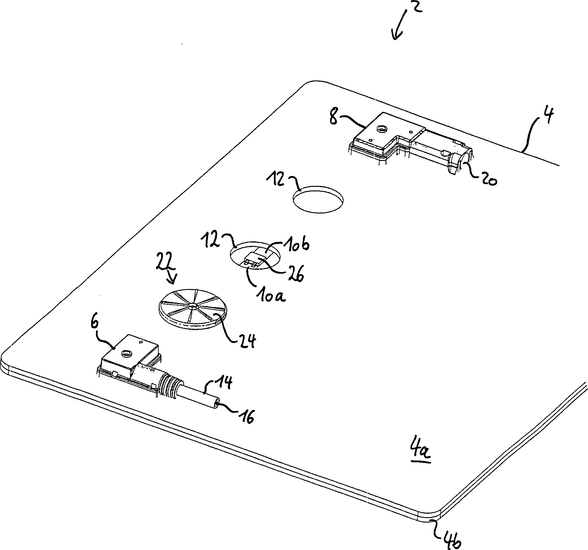
In
der
Vorzugsweise
ist die Diode
Ein
elektrischer Leiter (nicht gezeigt) ist mit dem Anschlußpol
der bereits befestigten Eingangsanschlußdose
Die
Eingangsanschlußdose
Wie
in
Anschließend
wird das Deckelements
Zur
weiteren Befestigung des Deckelements
Um
ein Ausgießen mit Kunstharz zu erleichtern weist das Deckelement
Das
Deckelement
Zusätzlich
oder alternativ kann auch ein Dichtungselement
- 22
- Solarpaneelsolar panel
- 44
- Solarmodulsolar module
- 4a4a
- AnschlußseitenelementConnecting side element
- 4b4b
- BeleuchtungsseitenelementSide lighting element
- 66
- EingangsanschlußdoseInput connection box
- 88th
- AusgangsanschlußdoseOutput junction box
- 10a, 10b10a, 10b
- elektrische Leiterelectrical ladder
- 1212
- Ausnehmungrecess
- 1414
- Kabelelectric wire
- 1616
- Leitungsadercable core
- 2020
- VerbinderInterconnects
- 2222
- Überbrückungseinrichtungbridging device
- 2424
- Deckelementcover element
- 2626
- Diodediode
- 28a, 28b28a, 28b
- Anschluß der DiodeConnection of the diode
- 3030
- Rastelementlocking element
- 3232
- Einfüllöffnungfill opening
- 3434
- Entlüftungsöffnungvent
- 3636
- Dichtungselementsealing element
ZITATE ENTHALTEN IN DER BESCHREIBUNGQUOTES INCLUDE IN THE DESCRIPTION
Diese Liste der vom Anmelder aufgeführten Dokumente wurde automatisiert erzeugt und ist ausschließlich zur besseren Information des Lesers aufgenommen. Die Liste ist nicht Bestandteil der deutschen Patent- bzw. Gebrauchsmusteranmeldung. Das DPMA übernimmt keinerlei Haftung für etwaige Fehler oder Auslassungen.This list The documents listed by the applicant have been automated generated and is solely for better information recorded by the reader. The list is not part of the German Patent or utility model application. The DPMA takes over no liability for any errors or omissions.
Zitierte Nicht-PatentliteraturCited non-patent literature
- - Norm IP67 [0021] - IP67 standard [0021]
- - Norm IP67 [0027] - standard IP67 [0027]
Claims (11)
Priority Applications (1)
| Application Number | Priority Date | Filing Date | Title |
|---|---|---|---|
| DE202010000710U DE202010000710U1 (en) | 2009-01-08 | 2010-01-08 | solar panel |
Applications Claiming Priority (3)
| Application Number | Priority Date | Filing Date | Title |
|---|---|---|---|
| DE102009004100.1 | 2009-01-08 | ||
| DE102009004100A DE102009004100A1 (en) | 2009-01-08 | 2009-01-08 | Solar panel for generating electrical energy from sunlight, has electrical conductors sectionally arranged in recess and electrically connected by diode, and cover element fixed at connection side element and covering recess and diode |
| DE202010000710U DE202010000710U1 (en) | 2009-01-08 | 2010-01-08 | solar panel |
Publications (1)
| Publication Number | Publication Date |
|---|---|
| DE202010000710U1 true DE202010000710U1 (en) | 2010-05-20 |
Family
ID=42194488
Family Applications (2)
| Application Number | Title | Priority Date | Filing Date |
|---|---|---|---|
| DE102009004100A Ceased DE102009004100A1 (en) | 2009-01-08 | 2009-01-08 | Solar panel for generating electrical energy from sunlight, has electrical conductors sectionally arranged in recess and electrically connected by diode, and cover element fixed at connection side element and covering recess and diode |
| DE202010000710U Expired - Lifetime DE202010000710U1 (en) | 2009-01-08 | 2010-01-08 | solar panel |
Family Applications Before (1)
| Application Number | Title | Priority Date | Filing Date |
|---|---|---|---|
| DE102009004100A Ceased DE102009004100A1 (en) | 2009-01-08 | 2009-01-08 | Solar panel for generating electrical energy from sunlight, has electrical conductors sectionally arranged in recess and electrically connected by diode, and cover element fixed at connection side element and covering recess and diode |
Country Status (3)
| Country | Link |
|---|---|
| EP (1) | EP2386125B1 (en) |
| DE (2) | DE102009004100A1 (en) |
| WO (1) | WO2010079142A2 (en) |
Families Citing this family (3)
| Publication number | Priority date | Publication date | Assignee | Title |
|---|---|---|---|---|
| DE202012004526U1 (en) * | 2012-04-30 | 2012-06-06 | Solarworld Innovations Gmbh | photovoltaic module |
| US10562274B1 (en) | 2016-02-22 | 2020-02-18 | Apple Inc. | Glass fastening and sealing systems |
| DE102024106441A1 (en) * | 2024-03-06 | 2025-09-11 | Weidmüller Interface GmbH & Co. KG | Bypass element and photovoltaic module with at least one bypass element |
Family Cites Families (11)
| Publication number | Priority date | Publication date | Assignee | Title |
|---|---|---|---|---|
| DE10331780B4 (en) * | 2003-07-11 | 2005-06-09 | Günther Spelsberg GmbH & Co. KG | Electrical connection and connection box |
| JPH11330524A (en) * | 1998-05-20 | 1999-11-30 | Asahi Glass Co Ltd | Solar panel |
| DE10052529A1 (en) * | 2000-10-23 | 2002-05-16 | Dorma Gmbh & Co Kg | Solar energy module consists of cell layer between glass plates and having a mounted connector |
| DE20311183U1 (en) * | 2003-07-21 | 2004-07-08 | Tyco Electronics Amp Gmbh | Junction box for a solar panel and solar panel |
| DE20311184U1 (en) * | 2003-07-21 | 2004-02-19 | Tyco Electronics Amp Gmbh | Junction box for connection to a solar panel |
| JP2005303049A (en) * | 2004-04-13 | 2005-10-27 | Sumitomo Wiring Syst Ltd | Terminal box for solar cell module |
| US8330035B2 (en) * | 2004-05-25 | 2012-12-11 | Kitani Electric Co., Ltd. | Terminal box for solar cell modules |
| DE502006008126D1 (en) * | 2005-01-14 | 2010-12-02 | Multi Holding Ag | Junction box for a solar panel |
| DE102005020129A1 (en) * | 2005-04-29 | 2006-11-09 | Tyco Electronics Amp Gmbh | Solar module for generating electrical energy |
| DE102006019210B4 (en) * | 2006-04-21 | 2013-09-05 | Telegärtner Gerätebau GmbH | Junction box arrangement for solar modules and method for producing a junction box arrangement for solar modules |
| ES2370863T3 (en) * | 2007-04-13 | 2011-12-23 | Huber+Suhner Ag | CONNECTION BOX |
-
2009
- 2009-01-08 DE DE102009004100A patent/DE102009004100A1/en not_active Ceased
-
2010
- 2010-01-08 WO PCT/EP2010/000064 patent/WO2010079142A2/en not_active Ceased
- 2010-01-08 DE DE202010000710U patent/DE202010000710U1/en not_active Expired - Lifetime
- 2010-01-08 EP EP10701094.4A patent/EP2386125B1/en active Active
Non-Patent Citations (1)
| Title |
|---|
| Norm IP67 |
Also Published As
| Publication number | Publication date |
|---|---|
| WO2010079142A3 (en) | 2011-09-22 |
| DE102009004100A1 (en) | 2010-07-15 |
| EP2386125A2 (en) | 2011-11-16 |
| WO2010079142A2 (en) | 2010-07-15 |
| EP2386125B1 (en) | 2017-10-18 |
Similar Documents
| Publication | Publication Date | Title |
|---|---|---|
| DE102008003448B4 (en) | Junction box, use, solar panel, contact element, and procedure | |
| DE102005025632B4 (en) | Connecting device for connecting electrical foil conductors | |
| EP2286462B1 (en) | Connection box, uses of a connection box and method | |
| EP2118977B1 (en) | Junction box and connecting box for a solar module | |
| DE102007043178A1 (en) | Junction box, solar panel, contact device and procedure | |
| DE102008052348A1 (en) | Connecting device for connecting an electrical conductor with a solar module and method for their preparation, and solar module with such a connection device | |
| DE102010002565B3 (en) | Connection device for a solar module | |
| DE102008023108A1 (en) | Edge connector for use in connecting arrangement for solar module, comprises electrical connection area for electrically connecting diode with connection element, where connection element is connected with connecting foil conductor | |
| EP2386125B1 (en) | Solar panel and method of manufacturing the same | |
| DE102009022944A1 (en) | Connection box for solar module of solar panel, has connection box fastening part and connector provided with connection pole or cable with line conductor | |
| DE202010000052U1 (en) | Photovoltaic module with a junction box | |
| EP2436038B1 (en) | Solar panel, method for producing the same and bypass plug | |
| EP2256825B1 (en) | Connection or bridging socket with soldering agent reservoir | |
| DE102008056282A1 (en) | Connecting device for a photovoltaic solar module | |
| EP2339646B1 (en) | Solar module, connection socket, solar module connection assembly, method and application | |
| EP2296181A2 (en) | Connection socket, use of same, solar panel and method | |
| DE102008056283A1 (en) | Connecting device for a photovoltaic solar module | |
| DE102012006033A1 (en) | Electrical installation and connecting device for solar cell module, has connectors electrically connected to bus bars and partially received in housing that is designed as component of solar cell module comprising frame | |
| DE102008057327B3 (en) | Solar panel, method of manufacturing and bridging box | |
| DE202009007523U1 (en) | Solar panel, junction box and jumper box | |
| DE202009007524U1 (en) | Solar connection or transfer box with solder depot | |
| EP2490266B1 (en) | Connection box, method for production and use of the connection box | |
| DE202011002913U1 (en) | junction box | |
| EP3018780B1 (en) | Electrical connection cable for lamp module | |
| EP4160908A1 (en) | Photovoltaic module and connection assembly for a photovoltaic module |
Legal Events
| Date | Code | Title | Description |
|---|---|---|---|
| R207 | Utility model specification |
Effective date: 20100624 |
|
| R150 | Utility model maintained after payment of first maintenance fee after three years | ||
| R150 | Utility model maintained after payment of first maintenance fee after three years |
Effective date: 20130208 |
|
| R082 | Change of representative |
Representative=s name: MUELLER-BORE & PARTNER PATENTANWAELTE, EUROPEA, DE |
|
| R081 | Change of applicant/patentee |
Owner name: YAMAICHI ELECTRONICS DEUTSCHLAND GMBH, DE Free format text: FORMER OWNER: YAMAICHI ELECTRONICS DEUTSCHLAND GMBH, 81829 MUENCHEN, DE Effective date: 20130409 |
|
| R082 | Change of representative |
Representative=s name: MUELLER-BORE & PARTNER PATENTANWAELTE PARTG MB, DE Effective date: 20130409 Representative=s name: MUELLER-BORE & PARTNER PATENTANWAELTE, EUROPEA, DE Effective date: 20130409 |
|
| R151 | Utility model maintained after payment of second maintenance fee after six years | ||
| R079 | Amendment of ipc main class |
Free format text: PREVIOUS MAIN CLASS: H01L0031050000 Ipc: H02S0040340000 |
|
| R152 | Utility model maintained after payment of third maintenance fee after eight years | ||
| R071 | Expiry of right |