DE202009017097U1 - Endoscope especially for minimally invasive spine surgery - Google Patents
Endoscope especially for minimally invasive spine surgery Download PDFInfo
- Publication number
- DE202009017097U1 DE202009017097U1 DE202009017097U DE202009017097U DE202009017097U1 DE 202009017097 U1 DE202009017097 U1 DE 202009017097U1 DE 202009017097 U DE202009017097 U DE 202009017097U DE 202009017097 U DE202009017097 U DE 202009017097U DE 202009017097 U1 DE202009017097 U1 DE 202009017097U1
- Authority
- DE
- Germany
- Prior art keywords
- endoscope according
- optical
- endoscope
- outer tube
- image
- Prior art date
- Legal status (The legal status is an assumption and is not a legal conclusion. Google has not performed a legal analysis and makes no representation as to the accuracy of the status listed.)
- Expired - Lifetime
Links
- 238000001356 surgical procedure Methods 0.000 title description 3
- 230000003287 optical effect Effects 0.000 claims abstract description 54
- 239000003365 glass fiber Substances 0.000 claims abstract description 15
- 238000005286 illumination Methods 0.000 claims abstract description 14
- 238000011010 flushing procedure Methods 0.000 claims abstract description 11
- 238000002324 minimally invasive surgery Methods 0.000 claims abstract description 3
- 230000001681 protective effect Effects 0.000 claims description 17
- 239000013307 optical fiber Substances 0.000 claims description 10
- 229920001296 polysiloxane Polymers 0.000 claims description 8
- 230000001154 acute effect Effects 0.000 claims description 5
- 239000003822 epoxy resin Substances 0.000 claims description 5
- 229920000647 polyepoxide Polymers 0.000 claims description 5
- 229910001220 stainless steel Inorganic materials 0.000 claims description 5
- 239000010935 stainless steel Substances 0.000 claims description 5
- 238000007789 sealing Methods 0.000 claims description 3
- 230000008878 coupling Effects 0.000 claims description 2
- 238000010168 coupling process Methods 0.000 claims description 2
- 238000005859 coupling reaction Methods 0.000 claims description 2
- 238000003801 milling Methods 0.000 claims description 2
- 238000010926 purge Methods 0.000 claims description 2
- 238000011109 contamination Methods 0.000 claims 1
- 239000000835 fiber Substances 0.000 description 12
- 239000004020 conductor Substances 0.000 description 8
- 238000003384 imaging method Methods 0.000 description 6
- 230000005540 biological transmission Effects 0.000 description 5
- 239000012530 fluid Substances 0.000 description 2
- BUHVIAUBTBOHAG-FOYDDCNASA-N (2r,3r,4s,5r)-2-[6-[[2-(3,5-dimethoxyphenyl)-2-(2-methylphenyl)ethyl]amino]purin-9-yl]-5-(hydroxymethyl)oxolane-3,4-diol Chemical compound COC1=CC(OC)=CC(C(CNC=2C=3N=CN(C=3N=CN=2)[C@H]2[C@@H]([C@H](O)[C@@H](CO)O2)O)C=2C(=CC=CC=2)C)=C1 BUHVIAUBTBOHAG-FOYDDCNASA-N 0.000 description 1
- 210000000988 bone and bone Anatomy 0.000 description 1
- 230000007547 defect Effects 0.000 description 1
- 238000003745 diagnosis Methods 0.000 description 1
- 239000003989 dielectric material Substances 0.000 description 1
- 201000010099 disease Diseases 0.000 description 1
- 208000037265 diseases, disorders, signs and symptoms Diseases 0.000 description 1
- 239000003814 drug Substances 0.000 description 1
- 238000001839 endoscopy Methods 0.000 description 1
- 230000002262 irrigation Effects 0.000 description 1
- 238000003973 irrigation Methods 0.000 description 1
- 238000000034 method Methods 0.000 description 1
- 239000000203 mixture Substances 0.000 description 1
- 210000000944 nerve tissue Anatomy 0.000 description 1
- 238000000926 separation method Methods 0.000 description 1
- 230000008054 signal transmission Effects 0.000 description 1
Images


Classifications
-
- A—HUMAN NECESSITIES
- A61—MEDICAL OR VETERINARY SCIENCE; HYGIENE
- A61B—DIAGNOSIS; SURGERY; IDENTIFICATION
- A61B1/00—Instruments for performing medical examinations of the interior of cavities or tubes of the body by visual or photographical inspection, e.g. endoscopes; Illuminating arrangements therefor
- A61B1/313—Instruments for performing medical examinations of the interior of cavities or tubes of the body by visual or photographical inspection, e.g. endoscopes; Illuminating arrangements therefor for introducing through surgical openings, e.g. laparoscopes
- A61B1/3135—Instruments for performing medical examinations of the interior of cavities or tubes of the body by visual or photographical inspection, e.g. endoscopes; Illuminating arrangements therefor for introducing through surgical openings, e.g. laparoscopes for examination of the epidural or the spinal space
-
- A—HUMAN NECESSITIES
- A61—MEDICAL OR VETERINARY SCIENCE; HYGIENE
- A61B—DIAGNOSIS; SURGERY; IDENTIFICATION
- A61B1/00—Instruments for performing medical examinations of the interior of cavities or tubes of the body by visual or photographical inspection, e.g. endoscopes; Illuminating arrangements therefor
- A61B1/00163—Optical arrangements
- A61B1/00165—Optical arrangements with light-conductive means, e.g. fibre optics
- A61B1/00167—Details of optical fibre bundles, e.g. shape or fibre distribution
-
- A—HUMAN NECESSITIES
- A61—MEDICAL OR VETERINARY SCIENCE; HYGIENE
- A61B—DIAGNOSIS; SURGERY; IDENTIFICATION
- A61B1/00—Instruments for performing medical examinations of the interior of cavities or tubes of the body by visual or photographical inspection, e.g. endoscopes; Illuminating arrangements therefor
- A61B1/012—Instruments for performing medical examinations of the interior of cavities or tubes of the body by visual or photographical inspection, e.g. endoscopes; Illuminating arrangements therefor characterised by internal passages or accessories therefor
-
- A—HUMAN NECESSITIES
- A61—MEDICAL OR VETERINARY SCIENCE; HYGIENE
- A61B—DIAGNOSIS; SURGERY; IDENTIFICATION
- A61B1/00—Instruments for performing medical examinations of the interior of cavities or tubes of the body by visual or photographical inspection, e.g. endoscopes; Illuminating arrangements therefor
- A61B1/06—Instruments for performing medical examinations of the interior of cavities or tubes of the body by visual or photographical inspection, e.g. endoscopes; Illuminating arrangements therefor with illuminating arrangements
- A61B1/07—Instruments for performing medical examinations of the interior of cavities or tubes of the body by visual or photographical inspection, e.g. endoscopes; Illuminating arrangements therefor with illuminating arrangements using light-conductive means, e.g. optical fibres
Landscapes
- Health & Medical Sciences (AREA)
- Life Sciences & Earth Sciences (AREA)
- Surgery (AREA)
- Optics & Photonics (AREA)
- Physics & Mathematics (AREA)
- Biomedical Technology (AREA)
- Animal Behavior & Ethology (AREA)
- Radiology & Medical Imaging (AREA)
- Nuclear Medicine, Radiotherapy & Molecular Imaging (AREA)
- Engineering & Computer Science (AREA)
- Biophysics (AREA)
- Heart & Thoracic Surgery (AREA)
- Medical Informatics (AREA)
- Molecular Biology (AREA)
- Pathology (AREA)
- General Health & Medical Sciences (AREA)
- Public Health (AREA)
- Veterinary Medicine (AREA)
- Neurology (AREA)
- Orthopedic Medicine & Surgery (AREA)
- Endoscopes (AREA)
- Instruments For Viewing The Inside Of Hollow Bodies (AREA)
Abstract
Endoskop, insbesondere für die minimal-invasive Chirurgie, mit einem Handteil (2) mit einem starren rohrförmigen Außenrohr (10), in welchem mindestens ein rohrförmiger Arbeitskanal (11), ein rohrförmiger Spülkanal (13) und mindestens ein rohrförmiger optischer Kanal (12) vorgesehen sind, dadurch gekennzeichnet, dass die Kanäle innerhalb des Außenrohrs (10) derart asymmetrisch angeordnet sind, dass mittels eines lichtleitenden Glasfaserbündels in verbleibenden Freiräumen des Außenrohrs (10) eine maximale Beleuchtungsintensität erreichbar ist.Endoscope, in particular for minimally invasive surgery, having a handpiece (2) with a rigid tubular outer tube (10) in which at least one tubular working channel (11), a tubular flushing channel (13) and at least one tubular optical channel (12) are provided, characterized in that the channels within the outer tube (10) are arranged asymmetrically such that by means of a photoconductive glass fiber bundle in remaining free spaces of the outer tube (10) a maximum illumination intensity can be achieved.
Description
Die Erfindung betrifft ein Endoskop, insbesondere für die minimal-invasive Chirurgie, mit einem Handteil mit einem starren rohrförmigen Außenrohr, in welchem mindestens ein rohrförmiger Arbeitskanal, ein rohrförmiger Spülkanal und mindestens ein rohrförmiger optischer Kanal vorgesehen sind.The invention relates to an endoscope, in particular for minimally invasive surgery, with a handle with a rigid tubular outer tube, in which at least one tubular working channel, a tubular flushing channel and at least one tubular optical channel are provided.
In vielen Teilbereichen der Medizin, ist die Endoskopie eine weitverbreitete und erfolgreiche Methode in der Diagnostik und Therapie einer Vielzahl von Erkrankungen. Dabei hat es sich als zweckmäßig erwiesen, insbesondere bildgebende Endoskope mit Anordnungen zu versehen, die einen Kanal oder mehrere Kanäle beispielsweise zur Führung von Arbeitsgeräten aufweisen, wie dies in der
Ein weiteres Endoskop ist in
Es ist daher Aufgabe der Erfindung, eine Verbesserung für ein Endoskop, insbesondere für die Verwendung in der Wirbelsäulenchirurgie, zu schaffen, wobei eine einfache und handliche Verwendung von verschiedensten chirurgischen Werkzeugen möglich ist, und weiterhin der Arbeitsbereich bestmöglich ausgeleuchtet und eine hochauflösende Bildgebung gewährleistet wird.It is therefore an object of the invention to provide an improvement for an endoscope, in particular for use in spine surgery, wherein a simple and handy use of a variety of surgical tools is possible, and further the work area as best as possible illuminated and high-resolution imaging is guaranteed.
Die genannte Aufgabe wird bei einem Endoskop der eingangs genannten Art dadurch gelöst, dass die Kanäle innerhalb des Außenrohrs derart asymmetrisch angeordnet sind, so dass mittels eines lichtleitenden Glasfaserbündels in allen verbleibenden Freiräumen des Außenrohrs (
Vorrichtungen aus dielektrischem Material, die geeignet sind, Licht zu leiten, wie z. B. Glasfasern sind hierbei besonders bevorzugt. Nach dem Zweck der Lichtleitung ist zu unterscheiden zwischen lichtleitenden Glasfaserbündeln, sogenannte Lichtleitern, zur reinen faseroptischen Beleuchtung und bildleitenden Glasfaserbündeln, sogenannte Bildleitern, zur optischen Bildübertragung.Dielectric material devices suitable for directing light, e.g. As glass fibers are particularly preferred. According to the purpose of the light pipe is to distinguish between photoconductive glass fiber bundles, so-called light guides for pure fiber optic illumination and image-guiding glass fiber bundles, called image guides, for optical image transmission.
In einer besonders bevorzugten Ausführungsform ist vorgesehen, dass der optische Kanal mit einem solchen bildleitenden Glasfaserbündel, einem Bildleiter, gefüllt ist. Ein Bildleiter dient zur optischen Bildübertragung und ist ein Faserbündel bei dem am Ein- und Austritt die Fasern geometrisch gleich angeordnet sind, d. h. jeder Faser in der Lichteintritts- und der Lichtaustrittsebene dieselben geometrischen Orte oder Koordinaten zugeordnet sind.In a particularly preferred embodiment, it is provided that the optical channel is filled with such an image-conducting glass fiber bundle, an image guide. An image guide is used for optical image transmission and is a fiber bundle in which the fibers are arranged geometrically the same at the inlet and outlet, d. H. Each fiber in the light entrance and the light exit plane are assigned the same geometric locations or coordinates.
Ein Bildleiter hat in einer bevorzugten Ausgestaltung einen Durchmesser von 0,72 mm, weist einen Schutzmantel aus Silikon auf und besteht im Inneren aus Einzelfasern in der genannten geometrischen Anordnung mit einem Durchmesser von 0,6 mm. Die spezielle Zusammensetzung der Glasfaser ermöglicht aufgrund des hohen Transmissionskoeffizienten eine verlustarme Übertragung der Bildinformation. Weiterhin ist dadurch eine hochauflösende Glasfaser gegeben, die eine Auflösung zwischen 13.000 und 18.000 Bildpunkten (Pixel) erreicht. Die Erfindung sieht in bevorzugter Ausgestaltung vor, dass für eine zusätzliche Ausleuchtung des Arbeitsbereichs die verbleibenden Zwischenräume zwischen den Kanälen mit einem Epoxydharz und Lichtleitern gefüllt sind. Die zwischen Außenrohr und den Kanälen, wie Arbeits-, Spül- und optischem Kanal, verbleibenden Zwischenräume sind mit Lichtleitern und Epoxydharz gefüllt. Es können die gesamten Zwischenräume mit Lichtleitern gefüllt sein. Die Lichtleiter sind zur faseroptischen Beleuchtung verwendbar. Der so aufgefüllte Querschnitt ist größer als der eines vergleichbaren koaxialen Ringes eines starren Endoskops. Hierdurch ist eine leistungsstarke und homogene Ausleuchtung des Arbeitsbereichs gewährleistet.A picture guide in a preferred embodiment has a diameter of 0.72 mm, has a protective sheath made of silicone and consists in the interior of individual fibers in said geometric arrangement with a diameter of 0.6 mm. The special composition of the glass fiber allows low-loss transmission of the image information due to the high transmission coefficient. Furthermore, this gives a high-resolution glass fiber, which achieves a resolution between 13,000 and 18,000 pixels. The invention provides in a preferred embodiment, that for additional illumination of the work area, the remaining spaces between the channels are filled with an epoxy resin and optical fibers. The remaining between the outer tube and the channels, such as working, flushing and optical channel, gaps are filled with optical fibers and epoxy resin. It can be filled with light guides the entire spaces. The light guides are suitable for fiber optic illumination. The thus filled cross section is larger than that of a comparable coaxial ring of a rigid endoscope. This ensures a powerful and homogeneous illumination of the work area.
Weiterhin ist vorgesehen, dass der Arbeitskanal, der Spülkanal und der optische Kanal asymmetrisch innerhalb des Außenrohres angeordnet sind. Hierdurch wird gewährleistet, dass sowohl der optische Kanal als auch insbesondere der Arbeitskanal maximal groß ausgebildet sein können und Platz für weitere Funktionalitäten wie z. B. einen Spülkanal bleibt. Ein erfindungsgemäßes Endoskop weist insbesondere ein Außenrohr mit einer Länge von ca. 100 mm und einen äußeren Durchmesser von größer gleich 3,6 mm auf, wobei der Arbeitskanal einen Durchmesser von größer gleich 2,2 mm, der Spülkanal einen Durchmesser von größer gleich 0,7 mm und der optische Kanal einen Durchmesser von größer gleich 0,8 mm hat.Furthermore, it is provided that the working channel, the flushing channel and the optical channel are arranged asymmetrically within the outer tube. This ensures that both the optical channel and in particular the working channel can be designed to be maximally large and space for further functionalities such. B. remains a flushing channel. An endoscope according to the invention has in particular an outer tube with a length of about 100 mm and an outer diameter of greater than or equal to 3.6 mm, the working channel having a diameter of greater than or equal to 2.2 mm, the flushing channel having a diameter of greater than or equal to 0.7 mm and the optical channel having a diameter of greater than or equal to 0.8 mm.
Damit eine optimale Verbindung zu chirurgischen Werkzeugen bewerkstelligt wird, ist besonders bevorzugt vorgesehen, dass das Handteil einen Knotenteil aus Edelstahl aufweist. Der Knotenteil ist als Zusammenschluss von Luer-Lock-Anschlüssen für die verschiedenen Kanäle ausgebildet, wobei am proximalen Ende ein Luer-Lock-Anschluss zum Einführen und Anschließen von starren chirurgischen Werkzeugen, insbesondere Fräsern oder Bohrern, vorgesehen ist und, dass der Knotenteil des Handteils proximal einen weiteren Luer-Lock-Anschluss für eine Spüleinrichtung hat. Durch die mit dem Außenrohr fluchtende Ausbildung des Arbeitskanals ist bedingt, dass das Handteil proximal einen in einem spitzen Winkel vom Außenrohr abgewinkelt ausgebildeten Kanal für die Glasfaseroptik aufweist.So that an optimal connection to surgical tools is accomplished, it is particularly preferred that the handle has a knot part made of stainless steel. The node part is formed as an association of luer lock connections for the various channels, wherein at the proximal end of a luer lock connector for inserting and connecting rigid surgical tools, in particular routers or drills, is provided, and that the nodal part of the handle proximal another Luer-lock connection for a purging device has. By aligned with the outer tube training of the working channel is conditional that the handpiece has proximal a angled at an acute angle from the outer tube formed channel for the optical fiber optics.
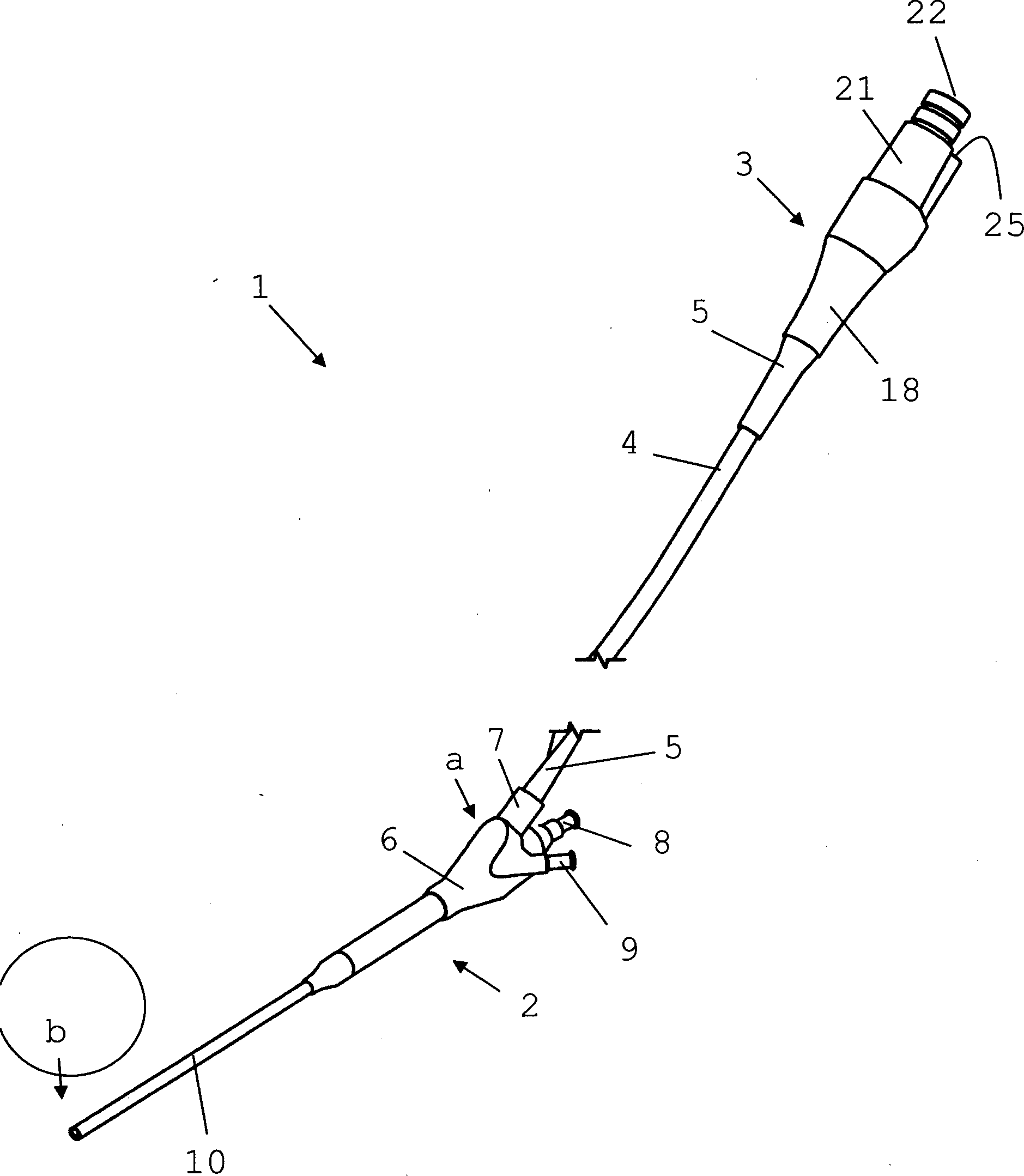
Für ein optimales bildgebendes Ergebnis ist besonders bevorzugt vorgesehen, dass das Handstück mit einem Optikteil über ein bildleitendes Glasfaserbündel verbunden ist, wobei der Bildleiter vom distalen Ende des Handteils bis zum proximalen Ende des Optikteils durchgängig ausgebildet. Das Optikteil enthält die erforderlichen Komponenten zur Auskopplung des Bildsignals aus dem Bildleiter. Durch die räumliche Trennung von einem Handteil und dem bildverarbeitenden Optikteil wird gewährleistet, dass das Handteil besonders leicht und handlich ausgebildet sein kann, womit ein Operateur leichter und präziser arbeiten kann. Um den beide Teile verbindenden Bildleiter vor äußeren Einflüssen zu schützen, ist vorgesehen, dass dieser von einem Schutzschlauch aus Silikon geschützt ist. Hierzu ist weiterhin vorgesehen, dass die Verbindungsstellen zwischen Handteil und Schutzschlauch bzw. Optikteil und Schutzschlauch einen Knickschutz aus Silikon aufweisen.For an optimal imaging result, it is particularly preferably provided that the handpiece is connected to an optical part via an image-conducting glass fiber bundle, the image conductor being formed continuously from the distal end of the handpiece to the proximal end of the optical part. The optical part contains the required components for decoupling the image signal from the image conductor. The spatial separation of a handset and the image-processing optical part ensures that the handset can be particularly lightweight and handy, making an operator easier and more precise work. In order to protect the image conductor connecting the two parts from external influences, it is provided that this is protected by a silicone protective tube. For this purpose, it is further provided that the joints between the handpiece and protective tube or optical part and protective tube have a kink protection made of silicone.
Für ein optimales Aufnahmeergebnis des Arbeitsbereiches ist in einer besonders bevorzugten Ausführungsform vorgesehen, dass der optische Kanal an einem distalen Ende des Handteils ein Objektiv zur Objektabbildung und ein distales Fenster zum Schutz des Objektivs vor Verschmutzungen aufweist.For an optimal recording result of the working area, it is provided in a particularly preferred embodiment that the optical channel has a lens for object imaging at a distal end of the handpiece and a distal window for protection of the objective from soiling.
Am proximalen Ende des Optikteils ist ein Lichtleiteranschluss angeordnet, durch welchen lichtleitende Glasfasern, sogenannte Lichtleiter, an das Optikteil ankoppelbar und verschiedenste Lichtquellen anschließbar sind. Für eine Auskopplung des Bildsignals aus dem Bildleiter sieht die Erfindung weiterhin vor, dass dem Bildleiter am proximalen Ende des Optikteils ein Linsensystem nachgeordnet ist, sowie, dass am proximalen Ende des Optikteils ein proximales Fenster zum Schutz des Linsensystems angeordnet ist. Dadurch, dass am proximalen Ende des Optikteils eine Verschlusskappe angeordnet ist, welche einen Anschluss aufweist, ist eine flexible Verbindung mit Kamera- und Lichteinrichtungen möglich.At the proximal end of the optical part, a light guide connection is arranged, through which photoconductive glass fibers, so-called light guides, can be coupled to the optical part and a variety of light sources can be connected. For a decoupling of the image signal from the image conductor, the invention further provides that the image conductor at the proximal end of the optical part, a lens system is arranged downstream, and that at the proximal end of the optical part, a proximal window for protecting the lens system is arranged. Characterized in that a closure cap is arranged at the proximal end of the optical part, which has a connection, a flexible connection with camera and light devices is possible.
Die spezielle Anordnung der verschiedenen Kanäle gewährleistet innerhalb des Endoskops eine maximale Auslastung des inneren Durchmessers des Außenrohrs. Zudem bietet das Endoskop den Vorteil, dass der Arbeitsteil und der optisch verarbeitende Teil räumlich getrennt sind, so dass ein handliches und folglich auch präziseres Arbeiten mit diesem Endoskop möglich ist.The special arrangement of the various channels ensures maximum utilization of the inner diameter of the outer tube within the endoscope. In addition, the endoscope has the advantage that the working part and the optically processing part are spatially separated, so that a handy and consequently more precise work with this endoscope is possible.
Weitere Vorteile und Merkmale der Erfindung ergeben sich aus den Ansprüchen und aus der nachfolgenden Beschreibung, in der eine bevorzugte Ausführungsform des erfindungsgemäßen Endoskops dargestellt ist. Dabei zeigt:Further advantages and features of the invention will become apparent from the claims and from the following description in which a preferred embodiment of the endoscope according to the invention is shown. Showing:
Die
Das Handteil
In
Die
Durch die spezielle Anordnung der verschiedenen Kanäle innerhalb des Endoskops ist eine maximale Ausnutzung des inneren Durchmessers gewährleistet. Die zwischen dem Außenrohr und den Kanälen verbleibenden Freiräume sind mit Lichtleitern
Bezugszeichenliste LIST OF REFERENCE NUMBERS
- 11
- Endoskopendoscope
- 22
- Handteilhandpiece
- 33
- OptikteilAn optical component
- 44
- SchutzschlauchConduit
- 55
- Knickschutzkink protection
- 66
- Knotenteilnode part
- 77
- optischer Anschlussoptical connection
- 88th
- Anschluss chirurgische WerkzeugeConnecting surgical tools
- 99
- SpülanschlussFlushing connection
- 1010
- Außenrohrouter tube
- 1111
- Arbeitskanalworking channel
- 1212
- optischer Kanaloptical channel
- 1313
- Spülkanalirrigation channel
- 1414
- Zwischenräumeinterspaces
- 1515
- Lichtleiteroptical fiber
- 1616
- Bildleiterimage conductor
- 1717
- Objektivlens
- 1818
- Endoskopkörper OptikteilEndoscope body optic part
- 1919
- Dichtelementsealing element
- 2020
- Linsensystemlens system
- 2121
- Verschlusskappecap
- 2222
- optischer Anschlussoptical connection
- 2323
- proximales Fensterproximal window
- 2424
- Ringdichtungring seal
- 2525
- LichtleiteranschlussOptical fiber connection
- aa
- proximales Ende Handteilproximal end of handpiece
- bb
- distales Ende Handteildistal end handpiece
- cc
- proximales Ende Optikteilproximal end optic part
ZITATE ENTHALTEN IN DER BESCHREIBUNG QUOTES INCLUDE IN THE DESCRIPTION
Diese Liste der vom Anmelder aufgeführten Dokumente wurde automatisiert erzeugt und ist ausschließlich zur besseren Information des Lesers aufgenommen. Die Liste ist nicht Bestandteil der deutschen Patent- bzw. Gebrauchsmusteranmeldung. Das DPMA übernimmt keinerlei Haftung für etwaige Fehler oder Auslassungen.This list of the documents listed by the applicant has been generated automatically and is included solely for the better information of the reader. The list is not part of the German patent or utility model application. The DPMA assumes no liability for any errors or omissions.
Zitierte PatentliteraturCited patent literature
- DE 19533856 A1 [0002] DE 19533856 A1 [0002]
- DE 2558081 [0003] DE 2558081 [0003]
Claims (18)
Priority Applications (2)
| Application Number | Priority Date | Filing Date | Title |
|---|---|---|---|
| DE202009017097U DE202009017097U1 (en) | 2009-12-18 | 2009-12-18 | Endoscope especially for minimally invasive spine surgery |
| PCT/EP2010/007639 WO2011079910A2 (en) | 2009-12-18 | 2010-12-15 | Endoscope, in particular for minimally invasive surgery on the spinal column |
Applications Claiming Priority (1)
| Application Number | Priority Date | Filing Date | Title |
|---|---|---|---|
| DE202009017097U DE202009017097U1 (en) | 2009-12-18 | 2009-12-18 | Endoscope especially for minimally invasive spine surgery |
Publications (1)
| Publication Number | Publication Date |
|---|---|
| DE202009017097U1 true DE202009017097U1 (en) | 2011-02-24 |
Family
ID=43662844
Family Applications (1)
| Application Number | Title | Priority Date | Filing Date |
|---|---|---|---|
| DE202009017097U Expired - Lifetime DE202009017097U1 (en) | 2009-12-18 | 2009-12-18 | Endoscope especially for minimally invasive spine surgery |
Country Status (2)
| Country | Link |
|---|---|
| DE (1) | DE202009017097U1 (en) |
| WO (1) | WO2011079910A2 (en) |
Cited By (3)
| Publication number | Priority date | Publication date | Assignee | Title |
|---|---|---|---|---|
| CN104783897A (en) * | 2015-03-11 | 2015-07-22 | 西安交通大学医学院第一附属医院 | Bundled multi-arm intelligent surgical operation auxiliary device |
| DE102018102587B3 (en) | 2018-02-06 | 2019-01-10 | Schölly Fiberoptic GmbH | Visualization module, endoscope and method for producing a visualization module |
| CN118749876A (en) * | 2024-04-02 | 2024-10-11 | 杭州思康新医疗科技有限公司 | An endoscope |
Families Citing this family (33)
| Publication number | Priority date | Publication date | Assignee | Title |
|---|---|---|---|---|
| US6793678B2 (en) | 2002-06-27 | 2004-09-21 | Depuy Acromed, Inc. | Prosthetic intervertebral motion disc having dampening |
| WO2008070863A2 (en) | 2006-12-07 | 2008-06-12 | Interventional Spine, Inc. | Intervertebral implant |
| US8900307B2 (en) | 2007-06-26 | 2014-12-02 | DePuy Synthes Products, LLC | Highly lordosed fusion cage |
| US8551173B2 (en) | 2008-01-17 | 2013-10-08 | DePuy Synthes Products, LLC | Expandable intervertebral implant and associated method of manufacturing the same |
| CA2720580A1 (en) | 2008-04-05 | 2009-10-08 | Synthes Usa, Llc | Expandable intervertebral implant |
| US9526620B2 (en) | 2009-03-30 | 2016-12-27 | DePuy Synthes Products, Inc. | Zero profile spinal fusion cage |
| US9393129B2 (en) | 2009-12-10 | 2016-07-19 | DePuy Synthes Products, Inc. | Bellows-like expandable interbody fusion cage |
| US9763678B2 (en) | 2010-06-24 | 2017-09-19 | DePuy Synthes Products, Inc. | Multi-segment lateral cage adapted to flex substantially in the coronal plane |
| US8979860B2 (en) | 2010-06-24 | 2015-03-17 | DePuy Synthes Products. LLC | Enhanced cage insertion device |
| US8623091B2 (en) | 2010-06-29 | 2014-01-07 | DePuy Synthes Products, LLC | Distractible intervertebral implant |
| US9402732B2 (en) | 2010-10-11 | 2016-08-02 | DePuy Synthes Products, Inc. | Expandable interspinous process spacer implant |
| US8518087B2 (en) | 2011-03-10 | 2013-08-27 | Interventional Spine, Inc. | Method and apparatus for minimally invasive insertion of intervertebral implants |
| US8394129B2 (en) | 2011-03-10 | 2013-03-12 | Interventional Spine, Inc. | Method and apparatus for minimally invasive insertion of intervertebral implants |
| WO2014018098A1 (en) | 2012-07-26 | 2014-01-30 | DePuy Synthes Products, LLC | Expandable implant |
| US20140067069A1 (en) | 2012-08-30 | 2014-03-06 | Interventional Spine, Inc. | Artificial disc |
| US9717601B2 (en) | 2013-02-28 | 2017-08-01 | DePuy Synthes Products, Inc. | Expandable intervertebral implant, system, kit and method |
| US9522070B2 (en) | 2013-03-07 | 2016-12-20 | Interventional Spine, Inc. | Intervertebral implant |
| US9277928B2 (en) | 2013-03-11 | 2016-03-08 | Interventional Spine, Inc. | Method and apparatus for minimally invasive insertion of intervertebral implants |
| US9993353B2 (en) | 2013-03-14 | 2018-06-12 | DePuy Synthes Products, Inc. | Method and apparatus for minimally invasive insertion of intervertebral implants |
| US11426290B2 (en) | 2015-03-06 | 2022-08-30 | DePuy Synthes Products, Inc. | Expandable intervertebral implant, system, kit and method |
| US9913727B2 (en) | 2015-07-02 | 2018-03-13 | Medos International Sarl | Expandable implant |
| WO2018002715A2 (en) | 2016-06-28 | 2018-01-04 | Eit Emerging Implant Technologies Gmbh | Expandable and angularly adjustable articulating intervertebral cages |
| WO2018002711A2 (en) | 2016-06-28 | 2018-01-04 | Eit Emerging Implant Technologies Gmbh | Expandable, angularly adjustable intervertebral cages |
| US10537436B2 (en) | 2016-11-01 | 2020-01-21 | DePuy Synthes Products, Inc. | Curved expandable cage |
| US10888433B2 (en) | 2016-12-14 | 2021-01-12 | DePuy Synthes Products, Inc. | Intervertebral implant inserter and related methods |
| US10398563B2 (en) | 2017-05-08 | 2019-09-03 | Medos International Sarl | Expandable cage |
| US11344424B2 (en) | 2017-06-14 | 2022-05-31 | Medos International Sarl | Expandable intervertebral implant and related methods |
| US10940016B2 (en) | 2017-07-05 | 2021-03-09 | Medos International Sarl | Expandable intervertebral fusion cage |
| US11446156B2 (en) | 2018-10-25 | 2022-09-20 | Medos International Sarl | Expandable intervertebral implant, inserter instrument, and related methods |
| US11426286B2 (en) | 2020-03-06 | 2022-08-30 | Eit Emerging Implant Technologies Gmbh | Expandable intervertebral implant |
| US11850160B2 (en) | 2021-03-26 | 2023-12-26 | Medos International Sarl | Expandable lordotic intervertebral fusion cage |
| US11752009B2 (en) | 2021-04-06 | 2023-09-12 | Medos International Sarl | Expandable intervertebral fusion cage |
| US12090064B2 (en) | 2022-03-01 | 2024-09-17 | Medos International Sarl | Stabilization members for expandable intervertebral implants, and related systems and methods |
Citations (5)
| Publication number | Priority date | Publication date | Assignee | Title |
|---|---|---|---|---|
| DE2558081A1 (en) | 1974-12-20 | 1976-07-22 | Olinger Charles P | FOCUSABLE NEEDLE ENDOSCOPE CONTAINING OPTICAL FIBERS |
| GB2255281A (en) * | 1991-03-06 | 1992-11-04 | Omega Universal Holdings | Articulated micro-endoscope |
| DE19533856A1 (en) | 1995-09-13 | 1997-03-20 | Balazs Mattias | Instrument for carrying out operations by minimal invasive techniques |
| US5785644A (en) * | 1996-07-12 | 1998-07-28 | Circon Corporation | Pivotal handle assembly for a video operating laparoscope |
| US20070232859A1 (en) * | 2006-02-24 | 2007-10-04 | U.S. Endoscopy Group, Inc. | Endoscopic suction device |
Family Cites Families (6)
| Publication number | Priority date | Publication date | Assignee | Title |
|---|---|---|---|---|
| US4173392A (en) * | 1977-07-20 | 1979-11-06 | American Hospital Supply Corporation | Glass fiber light guide and method of making the same |
| GB2068139A (en) * | 1980-01-30 | 1981-08-05 | Carson R W | Endoscope |
| US4392485A (en) * | 1981-02-17 | 1983-07-12 | Richard Wolf Gmbh | Endoscope |
| US5599278A (en) * | 1994-03-15 | 1997-02-04 | Erich M. N. Hibbard | Autoclavable rigid endoscope |
| EP1152684B1 (en) * | 1999-02-18 | 2003-12-17 | Karl Storz GmbH & Co. KG | Endoscope |
| JP2004337311A (en) * | 2003-05-14 | 2004-12-02 | Olympus Corp | Endoscope system |
-
2009
- 2009-12-18 DE DE202009017097U patent/DE202009017097U1/en not_active Expired - Lifetime
-
2010
- 2010-12-15 WO PCT/EP2010/007639 patent/WO2011079910A2/en not_active Ceased
Patent Citations (5)
| Publication number | Priority date | Publication date | Assignee | Title |
|---|---|---|---|---|
| DE2558081A1 (en) | 1974-12-20 | 1976-07-22 | Olinger Charles P | FOCUSABLE NEEDLE ENDOSCOPE CONTAINING OPTICAL FIBERS |
| GB2255281A (en) * | 1991-03-06 | 1992-11-04 | Omega Universal Holdings | Articulated micro-endoscope |
| DE19533856A1 (en) | 1995-09-13 | 1997-03-20 | Balazs Mattias | Instrument for carrying out operations by minimal invasive techniques |
| US5785644A (en) * | 1996-07-12 | 1998-07-28 | Circon Corporation | Pivotal handle assembly for a video operating laparoscope |
| US20070232859A1 (en) * | 2006-02-24 | 2007-10-04 | U.S. Endoscopy Group, Inc. | Endoscopic suction device |
Cited By (6)
| Publication number | Priority date | Publication date | Assignee | Title |
|---|---|---|---|---|
| CN104783897A (en) * | 2015-03-11 | 2015-07-22 | 西安交通大学医学院第一附属医院 | Bundled multi-arm intelligent surgical operation auxiliary device |
| CN104783897B (en) * | 2015-03-11 | 2017-01-25 | 西安交通大学医学院第一附属医院 | A clustered multi-arm intelligent surgical operation assisting device |
| DE102018102587B3 (en) | 2018-02-06 | 2019-01-10 | Schölly Fiberoptic GmbH | Visualization module, endoscope and method for producing a visualization module |
| US11006049B2 (en) | 2018-02-06 | 2021-05-11 | Schölly Fiberoptic GmbH | Visualization module and method for producing a visualization module |
| CN118749876A (en) * | 2024-04-02 | 2024-10-11 | 杭州思康新医疗科技有限公司 | An endoscope |
| CN119632483A (en) * | 2024-04-02 | 2025-03-18 | 杭州思康新医疗科技有限公司 | An endoscope |
Also Published As
| Publication number | Publication date |
|---|---|
| WO2011079910A2 (en) | 2011-07-07 |
| WO2011079910A3 (en) | 2011-09-01 |
Similar Documents
| Publication | Publication Date | Title |
|---|---|---|
| DE202009017097U1 (en) | Endoscope especially for minimally invasive spine surgery | |
| DE10348188B4 (en) | An ultrasonic endoscope | |
| EP1523932B1 (en) | Endoscope | |
| DE69931621T2 (en) | ENDOSCOPIC INSTRUMENT WITH WORK CHANNEL | |
| DE69734978T2 (en) | OPTICAL BIOPSIA TONGS | |
| DE69730426T2 (en) | SURGERY INSTRUMENT WITH VIEWING OPTICS AND ATRAUMATIC PROBE | |
| EP1152684B1 (en) | Endoscope | |
| DE69407238T2 (en) | Trocar with optics | |
| DE69827964T2 (en) | LENS SYSTEM FROM SAPHIR | |
| DE102005045729A1 (en) | Illumination system for endoscopic examinations | |
| EP0827711A1 (en) | Endoscopic surgical apparatus | |
| DE112016000132B4 (en) | ultrasound endoscope | |
| DE202005008569U1 (en) | Endoscopic instrument, comprising specifically arranged optical device, lighting device, and rinsing duct | |
| DE102005024352B4 (en) | Medical instrument for endoscopic procedures | |
| DE102022127796A1 (en) | EMBEDDED LASER FIBER FOR ASPIRATION STONE REMOVAL | |
| WO2019110816A1 (en) | Endoscope having a pivotable handle part | |
| EP2092873A1 (en) | Endoscope | |
| DE102015000773B4 (en) | Endoscope and method of making an endoscope | |
| EP1508066B1 (en) | Microendoscope | |
| WO2010105649A1 (en) | Tubular shaft of a surgical instrument and use of the same | |
| DE10000091A1 (en) | endoscope | |
| EP3613331A1 (en) | Endoscope with a movable component | |
| EP0858283A1 (en) | Rectoscope | |
| DE10359337B4 (en) | endoscope | |
| DE102024138870B3 (en) | Endoscope device and endoscope with an endoscope device |
Legal Events
| Date | Code | Title | Description |
|---|---|---|---|
| R163 | Identified publications notified | ||
| R207 | Utility model specification |
Effective date: 20110331 |
|
| R150 | Utility model maintained after payment of first maintenance fee after three years | ||
| R150 | Utility model maintained after payment of first maintenance fee after three years |
Effective date: 20130108 |
|
| R151 | Utility model maintained after payment of second maintenance fee after six years | ||
| R152 | Utility model maintained after payment of third maintenance fee after eight years | ||
| R071 | Expiry of right |