DE202007004475U1 - A filter assembly - Google Patents
A filter assembly Download PDFInfo
- Publication number
- DE202007004475U1 DE202007004475U1 DE202007004475U DE202007004475U DE202007004475U1 DE 202007004475 U1 DE202007004475 U1 DE 202007004475U1 DE 202007004475 U DE202007004475 U DE 202007004475U DE 202007004475 U DE202007004475 U DE 202007004475U DE 202007004475 U1 DE202007004475 U1 DE 202007004475U1
- Authority
- DE
- Germany
- Prior art keywords
- protuberance
- sealing
- filter
- adapter collar
- parallel
- Prior art date
- Legal status (The legal status is an assumption and is not a legal conclusion. Google has not performed a legal analysis and makes no representation as to the accuracy of the status listed.)
- Expired - Lifetime
Links
- 238000007789 sealing Methods 0.000 claims abstract description 56
- 230000037431 insertion Effects 0.000 claims abstract 2
- 238000003780 insertion Methods 0.000 claims abstract 2
- 210000002414 leg Anatomy 0.000 description 21
- 239000000463 material Substances 0.000 description 7
- 230000000694 effects Effects 0.000 description 4
- 230000015572 biosynthetic process Effects 0.000 description 2
- 210000003414 extremity Anatomy 0.000 description 2
- BUHVIAUBTBOHAG-FOYDDCNASA-N (2r,3r,4s,5r)-2-[6-[[2-(3,5-dimethoxyphenyl)-2-(2-methylphenyl)ethyl]amino]purin-9-yl]-5-(hydroxymethyl)oxolane-3,4-diol Chemical compound COC1=CC(OC)=CC(C(CNC=2C=3N=CN(C=3N=CN=2)[C@H]2[C@@H]([C@H](O)[C@@H](CO)O2)O)C=2C(=CC=CC=2)C)=C1 BUHVIAUBTBOHAG-FOYDDCNASA-N 0.000 description 1
- 239000011324 bead Substances 0.000 description 1
- 239000000919 ceramic Substances 0.000 description 1
- 238000004140 cleaning Methods 0.000 description 1
- 239000002131 composite material Substances 0.000 description 1
- 230000001419 dependent effect Effects 0.000 description 1
- 239000000428 dust Substances 0.000 description 1
- 230000005484 gravity Effects 0.000 description 1
- 238000010409 ironing Methods 0.000 description 1
- 230000002093 peripheral effect Effects 0.000 description 1
- 239000000825 pharmaceutical preparation Substances 0.000 description 1
- 229940127557 pharmaceutical product Drugs 0.000 description 1
- 210000000689 upper leg Anatomy 0.000 description 1
- 238000003466 welding Methods 0.000 description 1
Classifications
-
- B—PERFORMING OPERATIONS; TRANSPORTING
- B01—PHYSICAL OR CHEMICAL PROCESSES OR APPARATUS IN GENERAL
- B01D—SEPARATION
- B01D46/00—Filters or filtering processes specially modified for separating dispersed particles from gases or vapours
- B01D46/0002—Casings; Housings; Frame constructions
- B01D46/0005—Mounting of filtering elements within casings, housings or frames
-
- B—PERFORMING OPERATIONS; TRANSPORTING
- B01—PHYSICAL OR CHEMICAL PROCESSES OR APPARATUS IN GENERAL
- B01D—SEPARATION
- B01D46/00—Filters or filtering processes specially modified for separating dispersed particles from gases or vapours
- B01D46/24—Particle separators, e.g. dust precipitators, using rigid hollow filter bodies
- B01D46/2403—Particle separators, e.g. dust precipitators, using rigid hollow filter bodies characterised by the physical shape or structure of the filtering element
- B01D46/2407—Filter candles
-
- B—PERFORMING OPERATIONS; TRANSPORTING
- B01—PHYSICAL OR CHEMICAL PROCESSES OR APPARATUS IN GENERAL
- B01D—SEPARATION
- B01D46/00—Filters or filtering processes specially modified for separating dispersed particles from gases or vapours
- B01D46/56—Filters or filtering processes specially modified for separating dispersed particles from gases or vapours with multiple filtering elements, characterised by their mutual disposition
- B01D46/58—Filters or filtering processes specially modified for separating dispersed particles from gases or vapours with multiple filtering elements, characterised by their mutual disposition connected in parallel
- B01D46/60—Filters or filtering processes specially modified for separating dispersed particles from gases or vapours with multiple filtering elements, characterised by their mutual disposition connected in parallel arranged concentrically or coaxially
-
- B—PERFORMING OPERATIONS; TRANSPORTING
- B01—PHYSICAL OR CHEMICAL PROCESSES OR APPARATUS IN GENERAL
- B01D—SEPARATION
- B01D2201/00—Details relating to filtering apparatus
- B01D2201/04—Supports for the filtering elements
- B01D2201/043—Filter tubes connected to plates
- B01D2201/0446—Filter tubes connected to plates suspended from plates at the upper side of the filter elements
-
- B—PERFORMING OPERATIONS; TRANSPORTING
- B01—PHYSICAL OR CHEMICAL PROCESSES OR APPARATUS IN GENERAL
- B01D—SEPARATION
- B01D2201/00—Details relating to filtering apparatus
- B01D2201/34—Seals or gaskets for filtering elements
-
- B—PERFORMING OPERATIONS; TRANSPORTING
- B01—PHYSICAL OR CHEMICAL PROCESSES OR APPARATUS IN GENERAL
- B01D—SEPARATION
- B01D2271/00—Sealings for filters specially adapted for separating dispersed particles from gases or vapours
- B01D2271/02—Gaskets, sealings
- B01D2271/022—Axial sealings
-
- B—PERFORMING OPERATIONS; TRANSPORTING
- B01—PHYSICAL OR CHEMICAL PROCESSES OR APPARATUS IN GENERAL
- B01D—SEPARATION
- B01D2271/00—Sealings for filters specially adapted for separating dispersed particles from gases or vapours
- B01D2271/02—Gaskets, sealings
- B01D2271/027—Radial sealings
-
- B—PERFORMING OPERATIONS; TRANSPORTING
- B01—PHYSICAL OR CHEMICAL PROCESSES OR APPARATUS IN GENERAL
- B01D—SEPARATION
- B01D2275/00—Filter media structures for filters specially adapted for separating dispersed particles from gases or vapours
- B01D2275/20—Shape of filtering material
- B01D2275/206—Special forms, e.g. adapted to a certain housing
Landscapes
- Chemical & Material Sciences (AREA)
- Chemical Kinetics & Catalysis (AREA)
- Physics & Mathematics (AREA)
- Geometry (AREA)
- Filtering Of Dispersed Particles In Gases (AREA)
Abstract
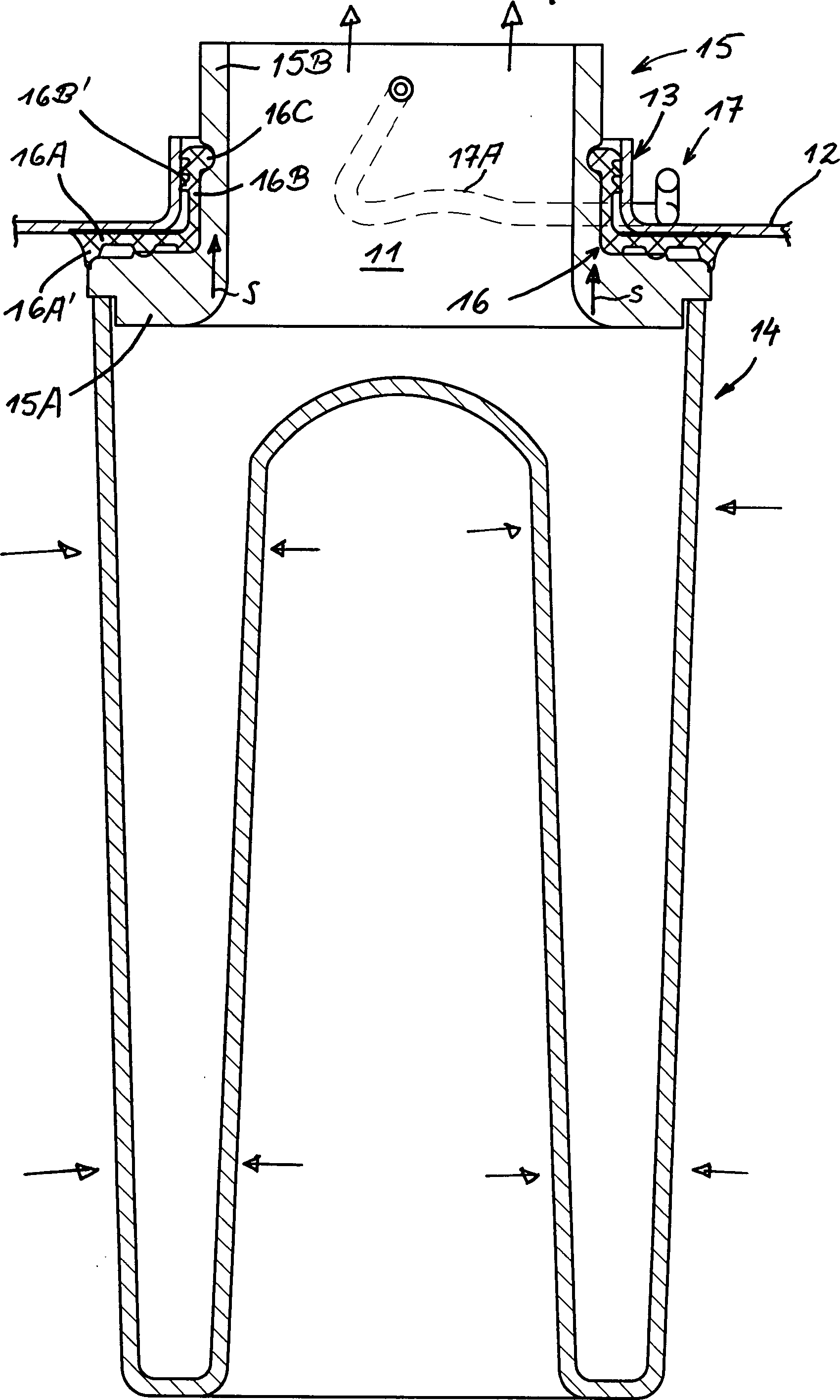
Filteranordnung zumindest umfassend einen plattenförmigen Filterhalter (12) mit mindestens einer Durchgangsöffnung (11) zur dichtenden Aufnahme eines mit einem Adapterkragen (15) versehenen Filterelementes (14) dadurch gekennzeichnet, dass der plattenförmige Filterhalter (12) eine halsförmige Ausstülpung (13) und der Adapterkragen (15) mindestens einen mit der Ausstülpung (13) ausstülpungsparallelen Schenkel (15B; 15D) aufweist, wobei die Schenkel in oder über die Ausstülpung (13) steckbar ist und dass eine Dichtanordnung (16) vorgesehen ist, die sowohl plattenparallele als auch ausstülpungsparallele Dichtelemente (16A, 16B) zum zumindest teilweisen Einfügen zwischen der Ausstülpung (13) und dem Adapterkragen (15) aufweist.A filter assembly at least comprising a plate-shaped filter holder (12) with at least one passage opening (11) for sealing Recording a provided with an adapter collar (15) filter element (14), characterized in that the plate-shaped filter holder (12) a neck-shaped protuberance (13) and the Adapter collar (15) at least one with the protuberance (13) protuberance-parallel legs (15B, 15D), the legs being in or over the protuberance (13) is pluggable and that a sealing arrangement (16) is provided which both plate-parallel and protuberance parallel Sealing elements (16A, 16B) for at least partial insertion between the protuberance (13) and the adapter collar (15) having.
Description
GEBIET DER ERFINDUNGFIELD OF THE INVENTION
Die Erfindung betrifft eine Filteranordnung gemäß dem Oberbegriff von Anspruch 1.The The invention relates to a filter arrangement according to the Preamble of claim 1.
TECHNOLOGISCHER HINTERGRUNDTECHNOLOGICAL BACKGROUND
Filterelemente,
die als Baueinheiten in einer dem Bedarf entsprechenden Anzahl in
einer Filteranordnung zusammengebaut werden können, werden üblicherweise
an einem plattenförmigen Filterhalter festgeschraubt. Hierzu
weist der plattenförmige Filterhalter Durchgangsöffnungen
auf, an deren Rand je ein Filterelement dichtend befestigt wird.
Ein typischer Anwendungsfall sind so genannte Vakuumförderanlagen,
wie sie aus der
DARSTELLUNG DER ERFINDUNGPRESENTATION OF THE INVENTION
Der Erfindung liegt die Aufgabe zugrunde, den Filterwechsel bei einer Filteranordnung der gattungsgemäßen Art bei ausreichender Filtersicherheit einfach zu gestalten.Of the Invention is based on the object, the filter change in a Filter arrangement of the generic type with sufficient Filter safety easy to design.
Zur Lösung dieser Aufgabe wird eine Filteranordnung mit den Merkmalen des Anspruchs 1 vorgeschlagen. Demnach ist vorgesehen, dass der plattenförmige Filterhalter eine halsförmige Ausstülpung und der Adapterkragen des Filterelementes eine plattenparallele und einen ausstülpungsparallelen Schenkel hat, wobei ein Dichtanordnung mit korrespondierenden plattenparallelen und ausstülpungsparallelen Dichtelementen versehen ist.to Solution to this problem is a filter arrangement with the Characteristics of claim 1 proposed. Accordingly, it is envisaged that the plate-shaped filter holder is a neck-shaped Protuberance and the adapter collar of the filter element a plate parallel and a protuberance parallel leg has, with a sealing arrangement with corresponding plate-parallel and everting parallel sealing elements is provided.
Auf diese Weise ist der Adapterkragen in die halsförmige Ausstülpung des plattenförmigen Filterhalters einsteckbar oder über sie überstülpbar. Dies kann in einer Weise geschehen, in der die Dichtanordnung an dem Adapterkragen bereits angelegt ist und somit gemeinsam mit dem Adapterkragen in oder über die halsförmige Ausstülpung des plattenförmigen Filterhalters ein- bzw. übergeschoben wird.On this way is the adapter collar in the neck-shaped protuberance the plate-shaped filter holder can be inserted or over they can be pushed over. This can be done in a way in which the sealing arrangement already applied to the adapter collar is and thus together with the adapter collar in or over the neck-shaped protuberance of the plate-shaped Filter holder is inserted or pushed over.
Halsförmige
Ausstülpungen an plattenförmigen Filterhaltern
sind zwar als solche bereits aus der
Zur Sicherung des Filterelementes am plattenförmigen Filterhalter kann bereits der Reibwiderstand der Dichtanordnung an der halsförmigen Ausstülpung ausreichen, wobei der an dem Filterelement anstehende Saugdruck die Dichtwirkung verstärkt. Bevorzugt ist eine Schnellverschlusssicherung an dem Adapterkragen vorgesehen, die sich z. B. durch einfaches Umlegen eines Sicherungsbügels so an der Rückseite des plattenförmigen Filterhalters anlegen lässt, dass der Adapterkragen dadurch in Sollposition gehalten wird. Selbst wenn diese Schnellverschlusssicherung versagt, sich z. B. öffnet, kann sie sicherstellen, dass das Filterelement an einem völligen Herausrutschen aus dem ausstülpungsparallelen Dichtungsbereich gehindert wird und somit eine Notsicherheit an Dichtwirkung erhalten bleibt.to Securing the filter element to the plate-shaped filter holder Already the frictional resistance of the sealing arrangement on the neck-shaped Ausstülpung sufficient, the pending on the filter element Suction pressure enhances the sealing effect. Preferred is a Quick lock provided on the adapter collar, the z. B. by simply moving a securing bracket so on the back of the plate-shaped filter holder can create that the adapter collar thereby in target position is held. Even if this quick-release lock fails, z. B. opens, it can make sure that the filter element at a complete slipping out of the protuberance parallel Sealing area is prevented and thus an emergency security Sealing effect is maintained.
Ein weiterer Aspekt ist die Hygiene, welche dadurch gesichert wird, dass das plattenparallele Dichtungselement die Verbindungs- und Dichtungsanordnung vor schädlicher Nesterbildung schützt.One Another aspect is the hygiene, which is ensured by that the plate-parallel sealing element, the connection and Seal arrangement protects against harmful formation of nests.
Die vorgenannten sowie die beanspruchten und in den Ausführungsbeispielen beschriebenen erfindungsgemäß zu verwendenden Bauteile unterliegen in ihrer Größe, Formgestaltung, Materialauswahl und technischen Konzeption keinen besonderen Ausnahmebedingungen, so dass die in dem Anwendungsgebiet bekannten Auswahlkriterien uneingeschränkt Anwendung finden könnenThe the aforementioned and the claimed and in the embodiments described to be used according to the invention Components are subject in size, shape design, Material selection and technical conception no special exceptions, so that the selection criteria known in the field of application unrestricted Application can be found
Weitere Einzelheiten, Merkmale und Vorteile des Gegenstandes der Erfindung ergeben sich aus den Unteransprüchen, sowie aus der nachfolgenden Beschreibung der zugehörigen Zeichnung und Tabelle, in der – beispielhaft – ein Ausführungsbeispiel einer Filteranordnung dargestellt sind.Further Details, features and advantages of the subject matter of the invention emerge from the dependent claims, as well as from the following description the accompanying drawing and table, in the - example - a Embodiment of a filter arrangement are shown.
In der Zeichnung zeigenIn show the drawing
Die
aus
Ein
Filterelement
Bei
dem Ausführungsbeispiel nach
Die
Ausführungsformen nach
Gemäß
Bei
dem Ausführungsbeispiel nach
Bei
dem Ausführungsbeispiel nach
Ein weiterer Aspekt ist die Hygiene, welche dadurch gesichert wird, dass das plattenparallele Dichtungselement die Verbindungs- und Dichtungsanordnung vor schädlicher Nesterbildung schützt. Insgesamt lässt sich durch die Erfindung eine an Spalten und Absätzen arme oder spalt- und absatzfreie Ordnung im Dichtungsbereich zwischen dem Filterhalter und dem Filterelement erreichen, so dass vor allem hygienischen Gesichtspunkten, wie sie bei z. B. pharmazeutischen Produkten eine besondere Rolle spielen, in besonders vorteilhafter Weise Rechnung getragen wird.One Another aspect is the hygiene, which is ensured by that the plate-parallel sealing element, the connection and Seal arrangement protects against harmful formation of nests. Overall, the invention allows one to columns and paragraphs poor or gap and paragraph free order in Sealing area between the filter holder and the filter element so that, above all, hygienic point of view, as they at z. B. pharmaceutical products play a special role, is taken into account in a particularly advantageous manner.
- 1010
- FilteranordnungA filter assembly
- 1111
- DurchgangsöffnungThrough opening
- 1212
- Filterhalterfilter holder
- 1313
- Ausstülpungprotuberance
- 13'13 '
- Dichtflächesealing surface
- 13''13 ''
- Dichtflächesealing surface
- 13''13 ''
- Dichtflächesealing surface
- 13A13A
- Umbördelungbeading
- 1414
- Filterelementfilter element
- 1515
- Adapterkragenadapter collar
- 15A15A
- plattenparalleler Schenkelplate parallel leg
- 156156
- ausstülpungsparalleler Schenkelausstülpungsparalleler leg
- 156'156 '
- ausstülpungsparallele Schenkelflächeausstülpungsparallele limb surface
- 15C15C
- Schraubmutternut
- 15C'15C '
- Schraubmutternut
- 15D15D
- Dichtschenkelsealing leg
- 15D'15D '
- ausstülpungsparallele Schenkelfächeausstülpungsparallele Schenkelfäche
- 15D''15D ''
- plattenparallele Schenkelflächeplate parallel limb surface
- 15E15E
- Rinnegutter
- 15F15F
- Aufnahmeaussparungreceiving recess
- 1616
- Dichtanordnungsealing arrangement
- 16A16A
- Dichtungselementsealing element
- 16A'16A '
- Dichtlippesealing lip
- 16B16B
- Dichtungselementsealing element
- 16B'16B '
- Dichtlippesealing lip
- 16C16C
- Vorsprunghead Start
- 1717
- SchnellverschlusssicherungQuick release safety
- 17A17A
- Sicherungsbügelsafety catch
- 18A/B18A / B
- Vernutung/VerrippungVernutung / ribbing
- SS
- Steckrichtungplug-in direction
ZITATE ENTHALTEN IN DER BESCHREIBUNGQUOTES INCLUDE IN THE DESCRIPTION
Diese Liste der vom Anmelder aufgeführten Dokumente wurde automatisiert erzeugt und ist ausschließlich zur besseren Information des Lesers aufgenommen. Die Liste ist nicht Bestandteil der deutschen Patent- bzw. Gebrauchsmusteranmeldung. Das DPMA übernimmt keinerlei Haftung für etwaige Fehler oder Auslassungen.This list The documents listed by the applicant have been automated generated and is solely for better information recorded by the reader. The list is not part of the German Patent or utility model application. The DPMA takes over no liability for any errors or omissions.
Zitierte PatentliteraturCited patent literature
- - DE 20312074 U1 [0002, 0006] - DE 20312074 U1 [0002, 0006]
Claims (13)
Priority Applications (6)
| Application Number | Priority Date | Filing Date | Title |
|---|---|---|---|
| DE202007004475U DE202007004475U1 (en) | 2007-03-23 | 2007-03-23 | A filter assembly |
| US12/532,467 US8349048B2 (en) | 2007-03-23 | 2008-05-16 | Filter arrangement |
| EP08758599A EP2155357B1 (en) | 2007-03-23 | 2008-05-16 | Filter arrangement |
| PCT/EP2008/003979 WO2008116672A2 (en) | 2007-03-23 | 2008-05-16 | Filter arrangement |
| CN2008800094887A CN101668575B (en) | 2007-03-23 | 2008-05-16 | Filter arrangement |
| JP2009553982A JP4987991B2 (en) | 2007-03-23 | 2008-05-16 | Filter configuration |
Applications Claiming Priority (1)
| Application Number | Priority Date | Filing Date | Title |
|---|---|---|---|
| DE202007004475U DE202007004475U1 (en) | 2007-03-23 | 2007-03-23 | A filter assembly |
Publications (1)
| Publication Number | Publication Date |
|---|---|
| DE202007004475U1 true DE202007004475U1 (en) | 2008-08-14 |
Family
ID=39688550
Family Applications (1)
| Application Number | Title | Priority Date | Filing Date |
|---|---|---|---|
| DE202007004475U Expired - Lifetime DE202007004475U1 (en) | 2007-03-23 | 2007-03-23 | A filter assembly |
Country Status (6)
| Country | Link |
|---|---|
| US (1) | US8349048B2 (en) |
| EP (1) | EP2155357B1 (en) |
| JP (1) | JP4987991B2 (en) |
| CN (1) | CN101668575B (en) |
| DE (1) | DE202007004475U1 (en) |
| WO (1) | WO2008116672A2 (en) |
Cited By (1)
| Publication number | Priority date | Publication date | Assignee | Title |
|---|---|---|---|---|
| DE102011106502A1 (en) | 2011-06-15 | 2012-12-20 | Mann + Hummel Gmbh | Filter element and housing for a filter element |
Families Citing this family (12)
| Publication number | Priority date | Publication date | Assignee | Title |
|---|---|---|---|---|
| DE202008004290U1 (en) * | 2008-03-27 | 2009-08-06 | Mann+Hummel Gmbh | Filter lock system |
| DE202009016500U1 (en) * | 2009-12-07 | 2010-02-25 | Mahle International Gmbh | Filter element and air filter |
| CN105209147B (en) | 2013-03-15 | 2020-07-03 | 唐纳森公司 | Filter Media and Elements |
| CA2842444C (en) * | 2013-04-03 | 2015-07-21 | Double T Equipment Ltd. | Curvable conveyor roller support |
| CN204147622U (en) * | 2014-06-03 | 2015-02-11 | 雅玛信过滤器株式会社 | Filter core and filter |
| EP3360609A1 (en) | 2017-02-10 | 2018-08-15 | Mann+Hummel GmbH | Filter element arrangement with an at least doubled safety filter element |
| DE112018000692T5 (en) * | 2017-03-16 | 2019-10-17 | Cummins Filtration Ip, Inc. | FILTRATION SEALING SYSTEM |
| KR102780590B1 (en) * | 2017-04-10 | 2025-03-12 | 파이로텍, 인크. | Filter handling tool |
| KR102292655B1 (en) * | 2017-04-26 | 2021-08-23 | 지브이에스 필트레이션, 인코포레이티드 | Multi Bead Air Filter Seal |
| DE102019127739A1 (en) * | 2019-10-15 | 2021-04-15 | Herding Gmbh Filtertechnik | Filter element, filter element holder for a filter element, a filter device, and a method for manufacturing a filter element |
| LU101650B1 (en) * | 2020-02-25 | 2021-08-25 | Luxembourg Patent Co | Closing member of a gas valve for very high pressure |
| DE102020128911A1 (en) | 2020-11-03 | 2022-05-05 | Mann+Hummel Gmbh | Filter system and filter element |
Citations (5)
| Publication number | Priority date | Publication date | Assignee | Title |
|---|---|---|---|---|
| DE816852C (en) * | 1947-09-10 | 1951-10-15 | Marie Meyer | Holding device for filter bags |
| US3997305A (en) * | 1976-03-05 | 1976-12-14 | Flex-Kleen Corporation | Support for bottom removal dust collector bag assembly |
| DE9014198U1 (en) * | 1990-10-12 | 1991-03-07 | Thomas Josef Heimbach GmbH & Co, 5160 Düren | Filters, especially hot gas filters |
| DE4134679A1 (en) * | 1991-10-21 | 1993-04-22 | Wilfried Dipl Ing Pergande | Reverse jet dust filter with sec. induced draught cleaning of bag support head - reduces re-deposition of dust |
| DE20312074U1 (en) | 2003-08-05 | 2004-12-23 | Volkmann Gmbh | Vacuum conveyor with a multi-stage filter system |
Family Cites Families (20)
| Publication number | Priority date | Publication date | Assignee | Title |
|---|---|---|---|---|
| DE1851221U (en) | 1961-06-14 | 1962-05-10 | Alfred Knecht | LUBRICATING OIL FILTERS, IN PARTICULAR FOR COMBUSTION MACHINES. |
| US4073632A (en) * | 1975-07-07 | 1978-02-14 | United States Filter Corporation | Filter bag assembly |
| DE7708188U1 (en) * | 1977-03-17 | 1977-06-30 | Uop-Kavag, 6467 Hasselroth | SCREW HOLDER FOR FILTER TUBE |
| JPS5982920A (en) * | 1982-11-02 | 1984-05-14 | Kobe Steel Ltd | Construction for attaching dust collecting filter |
| JPS6148021U (en) * | 1984-09-01 | 1986-03-31 | 喜久夫 藤村 | Filters for dust collectors, etc. |
| JPH056862Y2 (en) * | 1989-09-18 | 1993-02-22 | ||
| JPH0359009U (en) * | 1989-10-09 | 1991-06-10 | ||
| DE4031375A1 (en) | 1989-10-17 | 1991-04-25 | Sueddeutsche Kalkstickstoff | Dust extraction from flue gases - by perforated plate with weighted inserted tubular filter elements |
| DE4201041A1 (en) | 1991-09-20 | 1993-07-22 | Knecht Filterwerke Gmbh | Filter for liquids, esp. internal combustion engine lubricants |
| US5202021A (en) * | 1991-08-26 | 1993-04-13 | Hosokawa Micron International Inc. | Integrated molded collar, filter bag, cage and locking ring assembly for baghouses |
| DE4241586C1 (en) * | 1992-12-10 | 1994-01-27 | Mann & Hummel Filter | Air filter |
| US5401406A (en) | 1992-12-11 | 1995-03-28 | Pall Corporation | Filter assembly having a filter element and a sealing device |
| JPH07136442A (en) * | 1993-11-17 | 1995-05-30 | Mitsubishi Heavy Ind Ltd | Device for attaching filter element |
| US6004366A (en) * | 1994-11-23 | 1999-12-21 | Donaldson Company, Inc. | Reverse flow air filter arrangement and method |
| JPH10263337A (en) * | 1997-03-28 | 1998-10-06 | Kubota Corp | Metallic porous filter device |
| US5964909A (en) * | 1998-09-04 | 1999-10-12 | Brunner; David | Filter cartridge sealing method |
| FR2791579A1 (en) * | 1999-04-02 | 2000-10-06 | Albrecht Philippe | Oil or fuel filter cartridge for e.g. vehicle, has annular plastic joint molded over each end face of cylindrical filter element, with rigid layer molded over element and flexible resilient hub |
| US6858052B2 (en) * | 2003-05-30 | 2005-02-22 | Bha Group, Inc. | Filter cartridge mounting structure |
| DE102004005211B4 (en) * | 2004-02-03 | 2013-03-21 | Mahle Filtersysteme Gmbh | Annular filter element and associated manufacturing method |
| US20050229563A1 (en) * | 2004-04-19 | 2005-10-20 | Holzmann Mark V | Filter element |
-
2007
- 2007-03-23 DE DE202007004475U patent/DE202007004475U1/en not_active Expired - Lifetime
-
2008
- 2008-05-16 CN CN2008800094887A patent/CN101668575B/en active Active
- 2008-05-16 EP EP08758599A patent/EP2155357B1/en active Active
- 2008-05-16 JP JP2009553982A patent/JP4987991B2/en active Active
- 2008-05-16 US US12/532,467 patent/US8349048B2/en active Active
- 2008-05-16 WO PCT/EP2008/003979 patent/WO2008116672A2/en not_active Ceased
Patent Citations (5)
| Publication number | Priority date | Publication date | Assignee | Title |
|---|---|---|---|---|
| DE816852C (en) * | 1947-09-10 | 1951-10-15 | Marie Meyer | Holding device for filter bags |
| US3997305A (en) * | 1976-03-05 | 1976-12-14 | Flex-Kleen Corporation | Support for bottom removal dust collector bag assembly |
| DE9014198U1 (en) * | 1990-10-12 | 1991-03-07 | Thomas Josef Heimbach GmbH & Co, 5160 Düren | Filters, especially hot gas filters |
| DE4134679A1 (en) * | 1991-10-21 | 1993-04-22 | Wilfried Dipl Ing Pergande | Reverse jet dust filter with sec. induced draught cleaning of bag support head - reduces re-deposition of dust |
| DE20312074U1 (en) | 2003-08-05 | 2004-12-23 | Volkmann Gmbh | Vacuum conveyor with a multi-stage filter system |
Cited By (3)
| Publication number | Priority date | Publication date | Assignee | Title |
|---|---|---|---|---|
| DE102011106502A1 (en) | 2011-06-15 | 2012-12-20 | Mann + Hummel Gmbh | Filter element and housing for a filter element |
| WO2012172019A1 (en) | 2011-06-15 | 2012-12-20 | Mann+Hummel Gmbh | Air filter system, air filtering element and method for exchanging an air filtering element |
| EP3546048A1 (en) | 2011-06-15 | 2019-10-02 | Mann+Hummel GmbH | Air filter system, air filter element and method for exchanging an air filter element |
Also Published As
| Publication number | Publication date |
|---|---|
| US20110192126A1 (en) | 2011-08-11 |
| WO2008116672A3 (en) | 2008-11-27 |
| JP2011500304A (en) | 2011-01-06 |
| CN101668575B (en) | 2013-03-20 |
| WO2008116672A2 (en) | 2008-10-02 |
| EP2155357A2 (en) | 2010-02-24 |
| EP2155357B1 (en) | 2012-07-18 |
| US8349048B2 (en) | 2013-01-08 |
| JP4987991B2 (en) | 2012-08-01 |
| CN101668575A (en) | 2010-03-10 |
Similar Documents
| Publication | Publication Date | Title |
|---|---|---|
| DE202007004475U1 (en) | A filter assembly | |
| DE112010000811B4 (en) | FILTER DEVICE FOR FILTRATION OF GAS FLUIDS AND FILTER USE | |
| DE102014006853B4 (en) | Hollow filter element, filter housing and filter | |
| EP3082997B1 (en) | Treatment device for treating in particular liquid fluids and treatment element of a treatment device | |
| EP3082998B1 (en) | Treatment device for treating fluids, in particular liquid fluids, and treatment element of a treatment device | |
| DE202014104029U1 (en) | Filter attachable to a connection flange and filter element | |
| DE202007014821U1 (en) | Filter element V-seal | |
| EP1839723A1 (en) | Air filter and filter insert | |
| DE102015003297A1 (en) | Filter device and filter element, in particular for a motor vehicle | |
| DE102016005356A1 (en) | Filter element, in particular for gas filtration, and filter device | |
| DE102015007901A1 (en) | Filter element with pre-separator and filter system | |
| DE3826246A1 (en) | PROTECTIVE FILTER | |
| DE102010023974A1 (en) | Filter arrangement, in particular air filter arrangement | |
| DE202013102214U1 (en) | cartridge filters | |
| WO2018050237A1 (en) | Filter device, in particular air filter, for an air supply system of an internal combustion engine | |
| EP3501620A1 (en) | Supporting ring for fixing a filter cloth to a filter element | |
| DE102016224159A1 (en) | Ring filter element | |
| DE102010052592A1 (en) | Attachment of a master cylinder to a vehicle wall | |
| DE102015222425A1 (en) | Spin-on easy-change filter | |
| DE202016006508U1 (en) | Cartridge piston with bleeder valve | |
| WO2021078780A1 (en) | Treatment device for treating in particular liquid fluids, and treatment unit and connection head of a treatment device | |
| DE102019135091B4 (en) | Treatment device for the treatment of liquid fluids in particular and connection head of a treatment device | |
| DE102012012940A1 (en) | Filter holding frame for filter system for filtering e.g. gaseous fluid in air filter of motor car, has secondary sub-frame that is provided with filter element while other primary sub-frame is fixedly connected to detent connection | |
| DE102011011368A1 (en) | Apparatus for loading and venting closed housing, such as cabinet or control box, has mounting base which is designed for fixed attachment to housing, and cover that is rigidly mounted on mounting base | |
| DE19821360A1 (en) | Air filter, especially for combustion engines |
Legal Events
| Date | Code | Title | Description |
|---|---|---|---|
| R163 | Identified publications notified | ||
| R207 | Utility model specification |
Effective date: 20080918 |
|
| R150 | Utility model maintained after payment of first maintenance fee after three years |
Effective date: 20100604 |
|
| R151 | Utility model maintained after payment of second maintenance fee after six years | ||
| R151 | Utility model maintained after payment of second maintenance fee after six years |
Effective date: 20130204 |
|
| R152 | Utility model maintained after payment of third maintenance fee after eight years | ||
| R152 | Utility model maintained after payment of third maintenance fee after eight years |
Effective date: 20150512 |
|
| R071 | Expiry of right |