DE19944516B4 - Three-dimensional shape detection with camera images - Google Patents
Three-dimensional shape detection with camera images Download PDFInfo
- Publication number
- DE19944516B4 DE19944516B4 DE19944516A DE19944516A DE19944516B4 DE 19944516 B4 DE19944516 B4 DE 19944516B4 DE 19944516 A DE19944516 A DE 19944516A DE 19944516 A DE19944516 A DE 19944516A DE 19944516 B4 DE19944516 B4 DE 19944516B4
- Authority
- DE
- Germany
- Prior art keywords
- camera
- shape
- detected
- navigation system
- sharp
- Prior art date
- Legal status (The legal status is an assumption and is not a legal conclusion. Google has not performed a legal analysis and makes no representation as to the accuracy of the status listed.)
- Expired - Lifetime
Links
Classifications
-
- G—PHYSICS
- G01—MEASURING; TESTING
- G01B—MEASURING LENGTH, THICKNESS OR SIMILAR LINEAR DIMENSIONS; MEASURING ANGLES; MEASURING AREAS; MEASURING IRREGULARITIES OF SURFACES OR CONTOURS
- G01B11/00—Measuring arrangements characterised by the use of optical techniques
- G01B11/24—Measuring arrangements characterised by the use of optical techniques for measuring contours or curvatures
Landscapes
- Physics & Mathematics (AREA)
- General Physics & Mathematics (AREA)
- Image Processing (AREA)
Abstract
Verfahren
zur Erfassung einer Objektform und zur Verarbeitung der erfassten
Form, bei dem die Form eines zu behandelnden Körperteils eines Patienten als
Objekt erfasst wird, mit den folgenden Schritten:
a) ein Kamerabild
des Objektes wird erstellt;
b) ein Umriss des Objektes in einer
ersten Ebene, der in dem Kamerabild scharf erscheint, wird durch
eine mit der Kamera verbundene Auswertungseinheit erfasst;
c)
der Fokussierungsabstand der Kamera wird verändert;
d) ein scharfer
Umriss des Objektes in einer zweiten Ebene wird durch die Auswertungseinheit
erfasst;
e) die Schritte b) bis d) werden wiederholt, bis eine
ausreichende Zahl von Umrissen erfasst ist, so dass die räumliche
Form des Objektes festgestellt werden kann; und
f) ein das
Behandlungsgebiet überwachendes
Navigationssystem verarbeitet die erfasste Form so, dass die äußere Form
des Körperteils
bei der Navigation einbeziehbar wird.Method for detecting an object shape and processing the detected shape, in which the shape of a body part of a patient to be treated is detected as an object, comprising the following steps:
a) a camera image of the object is created;
b) an outline of the object in a first plane, which appears sharp in the camera image, is detected by an evaluation unit connected to the camera;
c) the focusing distance of the camera is changed;
d) a sharp outline of the object in a second plane is detected by the evaluation unit;
e) the steps b) to d) are repeated until a sufficient number of outlines are detected, so that the spatial form of the object can be determined; and
f) a navigation system monitoring the treatment area processes the detected shape so that the outer shape of the body part can be included in the navigation.
Description
Die vorliegende Erfindung betrifft ein Verfahren sowie eine Vorrichtung zur Erfassung einer Objektform.The The present invention relates to a method and a device to capture an object shape.
Es gibt verschiedene Anwendungen, bei denen es von Wichtigkeit ist, die äußere Form eines Objektes genau zu kennen. Eine solche Anwendung liegt beispielsweise auf dem Gebiet der Medizintechnik. So werden Patienten vor chirurgischen oder strahlentherapeutischen Maßnahmen z.B. mittels einer Computertomographie gescannt, um die Lage einer Gewebsveränderung im Körper oder in einem Körperteil festzustellen. Dabei werden auch Marker oder hervorgehobene Punkte am Körperteil mitgescannt, deren Positionsdaten später in einem chirurgischen Navigationssystem, das den Behandlungsraum interoperativ überwacht, um als Hilfestellung für den Chirurgen oder Strahlentherapeuten zu dienen, verwertet werden.It are different applications where it is important the outer shape of an object to know exactly. Such an application is, for example in the field of medical technology. So are patients before surgical or radiotherapeutic measures e.g. scanned by means of a computerized tomography to determine the location of a lesion in the body or in a body part determine. It will also markers or highlighted points on the body part scanned their position data later in a surgical Navigation system that interoperatively monitors the treatment room as an aid to the Surgeons or radiotherapists to serve, be recycled.
Bei solchen Verfahren muss nachteiligerweise vor der Behandlung mit Hilfe des Navigationssystems eine aufwendige Zuordnung der Lagedaten aus dem CT-Scan zu den tatsächlichen Raumdaten im Operationsraum erfolgen. Diese Zuordnung ist einerseits aufwendig, da entsprechende Marker auf der Haut per Hand mit einem Referenzierungsgerät angefahren und identifiziert werden müssen; andererseits ist sie des öfteren ungenau, da sich beispielsweise Hautmarker beim Referenzierungsvorgang sehr leicht verschieben können. Automatische Referenzierungen mit Markern oder anhand von natürlichen Landmarken sind sehr rechenaufwendig.at such process must be disadvantageously prior to treatment with Help the navigation system a complex assignment of the location data from the CT scan to the actual one Room data in the operating room done. This assignment is on the one hand consuming, as appropriate markers on the skin by hand with a Referenzierungsgerät have to be approached and identified; on the other hand, she is often inaccurate, as, for example, skin markers during the referencing process very can move easily. Automatic references with markers or natural ones Landmarks are very computationally intensive.
Ein weiterer Nachteil solcher Lage- und Formzuordnungsverfahren besteht darin, dass sie zum Zeitpunkt der Behandlung oder Operation nicht unbedingt die genauen tatsächlichen Lagedaten für die Außenform oder eine Innenform wiedergeben. Diese Formdaten stammen nämlich beispielsweise aus einer Computertomographie, die zeitlich vor dem Eingriff durchgeführt wurde und lediglich die Markerpositionen werden aktuell erfasst. Es kann nun vorkommen, dass sich durch Verschiebungen die Position von Gewebepunkten zu den Markern ändert, und zwar schon beim Transport vom Computertomographen in den Behandlungssaal. Dadurch wird die Form- und Lageerfassung im Navigationssystem unkorrekt und kann zu Fehlbehandlungen führen.One Another disadvantage of such position and shape allocation method consists in that they are not necessarily at the time of treatment or surgery the exact actual Location data for the external form or play an inner shape. For example, these shape data are derived a computed tomography performed before surgery and only the marker positions are currently detected. It can now happen that by shifting the position of tissue points changes to the markers, already during transport from the computer tomograph to the treatment room. As a result, the shape and position detection in the navigation system is incorrect and can lead to mistreatment.
Objektform-Erfassungstechniken
durch Kamerafokussierung sind für
Festkörper
bzw. starre Körper
bekannt. So wird beispielsweise in der
Es ist die Aufgabe der vorliegenden Erfindung, ein Verfahren sowie eine Vorrichtung zur Erfassung einer Objektform bereitzustellen, welche dazu in der Lage sind, die oben genannten Nachteile des Standes der Technik zu überwinden. Insbesondere soll eine schnelle und aktuell genaue Objektformerfassung ermöglicht werden.It It is the object of the present invention to provide a method as well to provide a device for detecting an object shape, which are capable of the above-mentioned disadvantages of the state overcome the technique. In particular, a fast and currently accurate object shape detection allows become.
Diese Aufgabe wird erfindungsgemäß durch ein Verfahren gemäß dem Anspruch 1 gelöst.These The object is achieved by a Method according to the claim 1 solved.
Dieses erfindungsgemäße Verfahren hat den großen Vorteil, dass es automatisch und sehr schnell erfolgen kann. Nach der Durchführung des Verfahrens steht die äußere Form des Objektes genau und vor allen Dingen aktuell fest, so dass hierauf folgende Referenzierungen ebenfalls mit einer hohen Genauigkeit durchgeführt werden können. Dies verkürzt insbesondere auf dem Gebiet der chirurgischen und strahlentherapeutischen Behandlungen die Vorbereitungszeit für den Eingriff, macht diese Eingriffsvorbereitung einfacher und unterstützt die Genauigkeit der Behandlung, wodurch Fehlbehandlungen vermieden werden können.This inventive method has the big one Advantage that it can be done automatically and very quickly. To the implementation the process is the external shape of the object exactly and above all things currently fixed, so that on this the following references also with a high accuracy carried out can be. This shortens especially in the field of surgical and radiotherapeutic Treatments the preparation time for the procedure, does this Intervention preparation easier and supports the accuracy of treatment, whereby mistreatment can be avoided.
Bei einer bevorzugten Ausführungsform der Erfindung wird durch eine Erfassung von Kontrastunterschieden festgestellt, welcher Umriss in dem Kamerabild scharf erscheint. Wenn in der Auswertungseinheit nunmehr bekannt ist, welcher Fokussierungsabstand vorliegt, werden in diesem Bereich, nämlich in dem Bereich der größten Schärfe des Bildes, auch die höchsten Kontrastunterschiede vorhanden sein. Demnach ist der gesuchte Umriss derjenige, bei dem die Kontrastunterschiede am höchsten sind, und sein Abstand, das heißt die Lage der Ebene, in der er von der Kamera entfernt liegt, ist bekannt, so dass auf dieser Ebene eine eindeutige Umrisszuordnung stattfinden kann. Es ist hierbei beispielsweise auch möglich, den Fokussierungsabstand bei der Erfassung eines Umrisses an einer Ebene vorübergehend zu variieren, um durch Mittelwertbildung die stärksten Kontrastunterschiede und damit die genaue Lage der gesuchten Ebene zu ermitteln.at a preferred embodiment The invention is characterized by a detection of contrast differences determines which outline appears sharp in the camera image. If it is now known in the evaluation unit which focusing distance are present in this area, namely in the area of greatest sharpness of the image, also the highest Contrast differences exist. Accordingly, the desired outline the one in which the contrast differences are highest, and its distance, this means the location of the plane away from the camera is known, so that at this level a unique outline mapping can take place. It is also possible, for example, the Focusing distance when capturing an outline on a plane temporarily to vary by averaging the strongest contrast differences and to determine the exact location of the searched plane.
Wenn dies für eine genügende Anzahl von Ebenen und Umrissen in diesen Ebenen erfolgt, kann damit eine äußerst genaue Erfassung der Objektform stattfinden.If this for a sufficient one Number of levels and outlines in these levels can be done with it a very accurate Capture the object shape take place.
Eine besonders genaue Umrisserfassung lässt sich erreichen, wenn eine Videokamera verwendet wird, deren Schärfentiefe sehr gering ist. Eine solche sehr geringe Schärfentiefe sorgt dafür, dass ein scharfer Umriss nur in einem sehr kleinen Abstandsbereich um den Fokussierungsabstand der Kamera herum erscheint. Mit einer Schärfentiefe, die gegen Null geht, könnte deshalb theoretisch der exakte Abstand der Ebene, in welcher der erfasste Umriss liegt, erfasst werden. Mit sehr geringen Schärfentiefen lassen sich deshalb sehr genaue Erfassungen vornehmen.A particularly accurate contour capture can be achieved when using a video camera det is, the depth of field is very low. Such a very shallow depth of field ensures that a sharp outline appears only in a very small distance range around the focusing distance of the camera. With a depth of field approaching zero, therefore, theoretically the exact distance of the plane in which the captured outline lies could be detected. With very small depths of field can therefore make very accurate observations.
Grundsätzlich können gemäß der Erfindung an dem zu erfassenden Objekt Markierungen angebracht werden, um bestimmte Objektpunkte eindeutig erfassbar zu machen. Es kann sich hierbei um Lichtmarkierungen, aufgesetzte Marker oder aufgeklebte Muster handeln, welche beispielsweise die Erfassung des schärfsten Bildes bzw. der höchsten Kontrastunterschiede vereinfachen.In principle, according to the invention the object to be detected markings are attached to certain Make object points clearly detectable. It can be this around light marks, patch markers or pasted patterns which, for example, capture the sharpest image or the highest contrast differences simplify.
Die Auswertungseinheit, die beim erfindungsgemäßen Verfahren verwendet wird, ist vorzugsweise ein Computer mit einem Bildverarbeitungsprogramm, wobei analoge Bildsignale (durch einen Analog-/Digitalwandler), die von der Kamera erfasst werden, digitalisiert und dann verarbeitet werden.The Evaluation unit used in the method according to the invention is preferably a computer with an image processing program, where analog image signals (by an analog / digital converter), which are captured by the camera, digitized and then processed become.
Eine besonders vorteilhafte Ausführungsform des erfindungsgemäßen Verfahrens wird dann erzielt, wenn die Kamera eine Kamera eines chirurgischen Mikroskops ist. Bei hohen Vergrößerungen wird nämlich die Schärfentiefe geringer, so dass die oben in diesem Zusammenhang schon angesprochenen Vorteile erzielt werden können. Im medizinischen Bereich und in Kombination mit einem Navigationssystem kann die vorliegende Erfindung grundsätzlich in zweierlei Art und Weise Anwendung finden. Einerseits kann die Form eines zu behandelnden Körperteils eines Patienten als Objekt erfasst werden, wobei die erfasste Form durch ein das Behandlungsgebiet überwachendes Navigationssystem verarbeitet wird, um so die äußere Form des Körperteils bei der Navigation einbeziehen zu können. Andererseits besteht die Möglichkeit, am Objekt mindestens einen durch das Navigationssystem erfassbaren Marker anzubringen, um die auch die von der Kamera erfasste Markerposition zu verwenden, um die Lage und Form des Objekts dem Navigationssystem zuzuordnen.A particularly advantageous embodiment the method according to the invention is achieved when the camera is a surgical camera Microscope is. At high magnifications will namely the depth of field lower, so the above in this context already mentioned Benefits can be achieved. In the medical field and in combination with a navigation system can the present invention basically in two ways and Find way application. On the one hand, the shape of a to be treated body part of a patient are detected as an object, the detected shape by a monitoring the treatment area Navigation system is processed so as to the outer shape of the body part to be included in the navigation. On the other hand exists the possibility, on the object at least one detectable by the navigation system Markers to match the marker position detected by the camera to use the location and shape of the object's navigation system assigned.
Natürlich können für die Zuordnung im Navigationssystem auch natürliche Landmarken und künstliche Marker in Kombination verwendet werden.Of course, for the assignment in the navigation system also natural Landmarks and artificial Markers are used in combination.
Wenn eine natürliche Landmarke zur Zuordnung verwendet wird, wird gemäß dem erfindungsgemäßen Verfahren am Objekt mindestens ein durch das Navigationssystem erfassbarer Punkt ausgewählt (beispielsweise die Nasenwurzel eines Patienten), um über die auch von der Kamera erfasste Position dieses Punktes bzw. mehrerer dieser Punkte die Lage und Form des Objekts dem Navigationssystem zuzuordnen.If a natural one Landmark is used for assignment, according to the inventive method at least one detectable by the navigation system on the object Point selected (for example, the nasal root of a patient) to talk about also detected by the camera position of this point or more these points the location and shape of the object the navigation system assigned.
Das erfindungsgemäße Verfahren kann zur Verifizierung und Aktualisierung der gewünschten Positionsdaten zusammen mit einem Navigationssystem zur Lagereferenzierung verwendet werden, und zwar vorzugsweise bei einem Strahlentherapieverfahren oder bei einem chirurgischen Eingriff. Dies erhöht die Behandlungsgenauigkeit.The inventive method can be used to verify and update the desired position data used together with a navigation system for location referencing be, preferably in a radiotherapy procedure or during a surgical procedure. This increases the accuracy of treatment.
Vorteilhafterweise wird hierbei die erfasste Form eines Körperteils derjenigen zugeordnet, welche durch ein präoperatives Scanverfahren, z.B. eine Computertomographie oder eine Kernspintomographie, bestimmt wurde. Hierdurch kann, auch wenn sich während des Patiententransportes eine Lageveränderung ergeben hat, also die CT- oder Kernspintomographie-Positionsdaten nicht mehr vollständig korrekt sind, ein Abgleich und eine Lagekorrektur durchgeführt werden, wodurch wiederum Fehlbehandlungen vermieden werden können. Ein großer Vorteil ist hierbei, dass der erfindungsgemäße Erfassungsvorgang durchaus auch während einer Operation, das heißt während eines chirurgischen Eingriffs, am offenen Körperteil vorgenommen werden kann. Dabei können natürlich auch die Umrisse in der geschaffenen Körperöffnung erfasst und zur Abgleichung des gescannten Bildes verwendet werden. Die schon entfernten Teile können dann auch in dem vom Navigationssystem gelieferten Bild ausgeschnitten werden, um dem behandelnden Chirurgen eine bessere und aktuellere Behandlungsunterstützung zu gewähren. Dabei werden jeweils beispielsweise Dichtewerte erstellt, die genau der neuen Oberfläche entsprechen.advantageously, in this case, the detected form of a body part is assigned to those which by a preoperative Scanning method, e.g. a computed tomography or magnetic resonance imaging, was determined. This may, even if during the patient transport a change of position has yielded, so the CT or MRI position data not complete anymore are correct, a balance and a location correction are performed which in turn can prevent mistreatment. One major advantage Here is that the detection process according to the invention certainly even while an operation, that is while surgery, on the open part of the body can. Of course, too the outlines in the created body opening captured and matched the scanned image. The already removed parts can then also be cut out in the image supplied by the navigation system, to give the treating surgeon better and more up-to-date treatment support. there In each case, for example, density values are created which are exactly the same correspond to new surface.
Des Weiteren kann das erfindungsgemäße Verfahren natürlich auch dazu verwendet werden, einen intelligenten Autofokus zur Verfügung zu stellen. Hierzu wird die erfasste Objektform, die in der Auswertungseinheit schon vorliegt, dazu verwendet, um automatisch durch den Benutzer vorgegebene Objektpunkte bzw. -ebenen zu fokussieren. Der Benutzer kann also beispielsweise in sein Navigationssystem eingeben, in welcher Umrissebene er ein scharfes Bild erhalten möchte, und zwar z.B. durch Koordinateneingabe oder durch die Verwendung eines taktilen Bildschirms. Die Kamera kann dann exakt diese Umrissebene fokussieren.Of Further, the inventive method Naturally also be used to provide a smart autofocus put. For this purpose, the detected object form, which is in the evaluation unit already exists, used to automatically by the user to focus on given object points or planes. The user So, for example, you can type in your navigation system, in which outline level he wants to get a sharp picture of, and although e.g. by entering coordinates or by using a tactile screen. The camera can then exactly this outline plane focus.
Ganz allgemein soll hier noch hinzugefügt werden, dass Objekte gemäß dem erfindungsgemäßen Verfahren durchaus von verschiedenen Seiten her aufgenommen werden können, wobei entweder über eine genau bekannte neue Kameraposition oder durch die Zuordnung von künstlichen Markern oder natürlichen Landmarken rechnerisch eine Zuordnung der beiden Erfassungen erfolgt, so dass ein Gesamtbild entsteht. Dadurch können auch Probleme vermieden werden, die durch Hinterschneidungen am Objekt entstehen und die Erfassung kann vervollständigt werden.In general, it should be added here that objects according to the method according to the invention can certainly be recorded from different sides, wherein an assignment either by means of a precisely known new camera position or by the assignment of artificial markers or natural landmarks the two acquisitions takes place, so that an overall picture is created. This can also avoid problems caused by undercuts on the object and the capture can be completed.
Die erfindungsgemäße Vorrichtung wird durch den Anspruch 13 definiert.The inventive device is defined by claim 13.
Wie schon oben erwähnt, ist es hierbei von Vorteil, wenn die Kamera eine Videokamera ist, deren Schärfentiefe sehr gering ist. Wie ebenfalls schon bei der Beschreibung des erfindungsgemäßen Verfahrens erläutert wurde, ist die Auswertungseinheit vorzugsweise ein Computer mit einem Bildverarbeitungsprogramm, wobei analoge Bildsignale, die von der Kamera erfasst werden, digitalisiert und dann verarbeitet werden und wobei das Bildverarbeitungsprogramm insbesondere durch eine Erfassung von Kontrastunterschieden feststellt, welcher Umriss in dem Kamerabild scharf erscheint. Die Kamera ist bevorzugt diejenige an einem chirurgischen Mikroskop.As already mentioned above, it is an advantage if the camera is a video camera, their depth of field is very low. As also in the description of the method according to the invention explained the evaluation unit is preferably a computer with an image processing program, wherein analog image signals, the captured by the camera, digitized and then processed and wherein the image processing program in particular by a detection of contrast differences determines which outline in the camera image appears sharp. The camera is preferably the one on a surgical microscope.
Die Erfindung wird nun im Weiteren anhand einer bevorzugten Ausführungsform und unter Bezugnahme auf die beiliegende Zeichnung näher erläutert.The The invention will now be described below with reference to a preferred embodiment and explained in more detail with reference to the accompanying drawings.
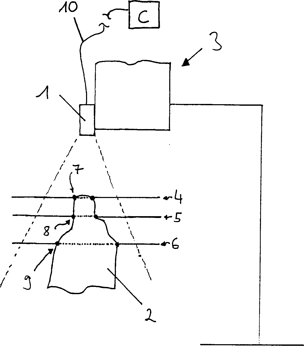
In
der Zeichnung ist schematisch eine erfindungsgemäße Vorrichtung zur Erfassung
der Form eines Objektes dargestellt. In dem dargestellten Beispiel
trägt das
vereinfacht dargestellte Mikroskop
Die
Videokamera
Das
Objekt
Beim
Anfahren der Ebenen
Wenn
dieser Vorgang dann für
weitere Ebenen, z.B. die Ebenen
Claims (16)
Priority Applications (2)
| Application Number | Priority Date | Filing Date | Title |
|---|---|---|---|
| DE19944516A DE19944516B4 (en) | 1999-09-16 | 1999-09-16 | Three-dimensional shape detection with camera images |
| US09/662,045 US6947582B1 (en) | 1999-09-16 | 2000-09-15 | Three-dimensional shape detection by means of camera images |
Applications Claiming Priority (1)
| Application Number | Priority Date | Filing Date | Title |
|---|---|---|---|
| DE19944516A DE19944516B4 (en) | 1999-09-16 | 1999-09-16 | Three-dimensional shape detection with camera images |
Publications (2)
| Publication Number | Publication Date |
|---|---|
| DE19944516A1 DE19944516A1 (en) | 2001-04-12 |
| DE19944516B4 true DE19944516B4 (en) | 2006-08-17 |
Family
ID=7922308
Family Applications (1)
| Application Number | Title | Priority Date | Filing Date |
|---|---|---|---|
| DE19944516A Expired - Lifetime DE19944516B4 (en) | 1999-09-16 | 1999-09-16 | Three-dimensional shape detection with camera images |
Country Status (2)
| Country | Link |
|---|---|
| US (1) | US6947582B1 (en) |
| DE (1) | DE19944516B4 (en) |
Cited By (1)
| Publication number | Priority date | Publication date | Assignee | Title |
|---|---|---|---|---|
| DE102017009804A1 (en) * | 2017-10-20 | 2019-04-25 | Vermicon Ag | Method for evaluating microscopic samples and apparatus for carrying out this method |
Families Citing this family (44)
| Publication number | Priority date | Publication date | Assignee | Title |
|---|---|---|---|---|
| DE10249025B4 (en) * | 2002-06-13 | 2007-06-14 | Möller-Wedel GmbH | Method for presence optimization in neuronavigation in surgery with a surgical microscope and at least one coupled to the observation beam path of the microscope optoelectronic image receptor and a computer system including navigation instrument therefor |
| ATE424776T1 (en) | 2002-10-04 | 2009-03-15 | Orthosoft Inc | COMPUTER-ASSISTED HIP REPLACEMENT SURGERY |
| CN102641561B (en) | 2004-02-20 | 2017-08-25 | 佛罗里达大学研究基金会公司 | For providing conformal radiation therapy while the system being imaged to soft tissue |
| EP1607064B1 (en) | 2004-06-17 | 2008-09-03 | Cadent Ltd. | Method and apparatus for colour imaging a three-dimensional structure |
| DE102004047928B4 (en) * | 2004-10-01 | 2011-02-24 | Carl Mahr Holding Gmbh | Optical 3D measuring method and measuring device |
| US9002432B2 (en) | 2004-11-15 | 2015-04-07 | Brainlab Ag | Method and device for calibrating a medical instrument |
| US7583272B2 (en) * | 2004-11-29 | 2009-09-01 | Purdue Research Foundation | Methods for retrieving shapes and drawings |
| US7840256B2 (en) * | 2005-06-27 | 2010-11-23 | Biomet Manufacturing Corporation | Image guided tracking array and method |
| US20070038059A1 (en) * | 2005-07-07 | 2007-02-15 | Garrett Sheffer | Implant and instrument morphing |
| US7643862B2 (en) | 2005-09-15 | 2010-01-05 | Biomet Manufacturing Corporation | Virtual mouse for use in surgical navigation |
| US8165659B2 (en) | 2006-03-22 | 2012-04-24 | Garrett Sheffer | Modeling method and apparatus for use in surgical navigation |
| EP1933276B1 (en) | 2006-12-11 | 2010-06-30 | BrainLAB AG | Multiband tracking and calibration system |
| US8934961B2 (en) | 2007-05-18 | 2015-01-13 | Biomet Manufacturing, Llc | Trackable diagnostic scope apparatus and methods of use |
| US20080319491A1 (en) | 2007-06-19 | 2008-12-25 | Ryan Schoenefeld | Patient-matched surgical component and methods of use |
| ES2447875T3 (en) | 2007-10-02 | 2014-03-13 | Theranos, Inc. | Modular devices for care points and their uses |
| US8571637B2 (en) | 2008-01-21 | 2013-10-29 | Biomet Manufacturing, Llc | Patella tracking method and apparatus for use in surgical navigation |
| JP5287385B2 (en) | 2009-03-13 | 2013-09-11 | オムロン株式会社 | Measuring device |
| US9030466B2 (en) * | 2010-10-05 | 2015-05-12 | Empire Technology Development Llc | Generation of depth data based on spatial light pattern |
| MX349288B (en) | 2011-01-21 | 2017-07-21 | Theranos Inc | Systems and methods for sample use maximization. |
| US9664702B2 (en) | 2011-09-25 | 2017-05-30 | Theranos, Inc. | Fluid handling apparatus and configurations |
| US9632102B2 (en) | 2011-09-25 | 2017-04-25 | Theranos, Inc. | Systems and methods for multi-purpose analysis |
| US20140170735A1 (en) | 2011-09-25 | 2014-06-19 | Elizabeth A. Holmes | Systems and methods for multi-analysis |
| US9619627B2 (en) | 2011-09-25 | 2017-04-11 | Theranos, Inc. | Systems and methods for collecting and transmitting assay results |
| US8435738B2 (en) | 2011-09-25 | 2013-05-07 | Theranos, Inc. | Systems and methods for multi-analysis |
| US8840838B2 (en) | 2011-09-25 | 2014-09-23 | Theranos, Inc. | Centrifuge configurations |
| US9268915B2 (en) * | 2011-09-25 | 2016-02-23 | Theranos, Inc. | Systems and methods for diagnosis or treatment |
| US8475739B2 (en) | 2011-09-25 | 2013-07-02 | Theranos, Inc. | Systems and methods for fluid handling |
| US9250229B2 (en) | 2011-09-25 | 2016-02-02 | Theranos, Inc. | Systems and methods for multi-analysis |
| US10012664B2 (en) | 2011-09-25 | 2018-07-03 | Theranos Ip Company, Llc | Systems and methods for fluid and component handling |
| US9810704B2 (en) | 2013-02-18 | 2017-11-07 | Theranos, Inc. | Systems and methods for multi-analysis |
| DE102011114932A1 (en) * | 2011-10-06 | 2013-04-11 | Hommel-Etamic Gmbh | Method for determining contour of upper surface of object along measuring section, involves varying focusing of microscope objective relative to upper surface along measuring axis over scan range at measuring paths |
| US10561861B2 (en) | 2012-05-02 | 2020-02-18 | Viewray Technologies, Inc. | Videographic display of real-time medical treatment |
| KR20150080527A (en) | 2012-10-26 | 2015-07-09 | 뷰레이 인코포레이티드 | Assessment and improvement of treatment using imaging of physiological responses to radiation therapy |
| US9446263B2 (en) | 2013-03-15 | 2016-09-20 | Viewray Technologies, Inc. | Systems and methods for linear accelerator radiotherapy with magnetic resonance imaging |
| TWI618640B (en) * | 2013-09-13 | 2018-03-21 | Silicon Touch Technology Inc. | Three dimensional printing system, and method for three dimensional printing |
| CN108367160A (en) | 2015-11-24 | 2018-08-03 | 优瑞技术公司 | Collimation of radiation beams system and method |
| DE102016101832A1 (en) * | 2016-02-02 | 2017-08-03 | Frt Gmbh | Method and measuring device for measuring the topography using at least two height levels of a surface |
| WO2017143427A1 (en) * | 2016-02-25 | 2017-08-31 | Synaptive Medical (Barbados) Inc. | System and method for scope based depth map acquisition |
| KR20180120705A (en) | 2016-03-02 | 2018-11-06 | 뷰레이 테크놀로지스 인크. | Particle therapy using magnetic resonance imaging |
| EP3475718B1 (en) | 2016-06-22 | 2025-08-13 | Viewray Systems, Inc. | Magnetic resonance imaging at low field strength |
| EP4338677A3 (en) | 2016-12-13 | 2024-06-19 | ViewRay Technologies, Inc. | Radiation therapy systems and methods |
| CN116036499A (en) | 2017-12-06 | 2023-05-02 | 优瑞技术公司 | Optimization of multi-modality radiation therapy |
| US11209509B2 (en) | 2018-05-16 | 2021-12-28 | Viewray Technologies, Inc. | Resistive electromagnet systems and methods |
| CN120418606A (en) * | 2023-11-30 | 2025-08-01 | 京东方科技集团股份有限公司 | Thickness determination method, thickness determination device, thickness determination apparatus, and storage medium |
Citations (5)
| Publication number | Priority date | Publication date | Assignee | Title |
|---|---|---|---|---|
| DE3406375A1 (en) * | 1984-02-22 | 1985-08-22 | SIGNUM Computer für Signalverarbeitung und Mustererkennung GmbH, 8000 München | Device for determining the surface profiles of non transparent material by digital evaluation of a sequence of micrographs having different focal planes |
| DE3511347C2 (en) * | 1985-03-28 | 1987-04-09 | Gerd Dipl.-Phys. Dr. 8520 Erlangen Häusler | Method and device for optical multidimensional shape detection of an object |
| US5151609A (en) * | 1989-08-02 | 1992-09-29 | Hitachi, Ltd. | Method of detecting solid shape of object with autofocusing and image detection at each focus level |
| US5446548A (en) * | 1993-10-08 | 1995-08-29 | Siemens Medical Systems, Inc. | Patient positioning and monitoring system |
| US5745239A (en) * | 1997-04-07 | 1998-04-28 | Taiwan Semiconductor Manufacturing Company | Multiple focal plane image comparison for defect detection and classification |
Family Cites Families (4)
| Publication number | Priority date | Publication date | Assignee | Title |
|---|---|---|---|---|
| US6006126A (en) * | 1991-01-28 | 1999-12-21 | Cosman; Eric R. | System and method for stereotactic registration of image scan data |
| GB9102903D0 (en) * | 1991-02-12 | 1991-03-27 | Oxford Sensor Tech | An optical sensor |
| JPH0560528A (en) * | 1991-09-03 | 1993-03-09 | Hitachi Ltd | Input device for three-dimensional information |
| US6088099A (en) * | 1996-10-30 | 2000-07-11 | Applied Spectral Imaging Ltd. | Method for interferometer based spectral imaging of moving objects |
-
1999
- 1999-09-16 DE DE19944516A patent/DE19944516B4/en not_active Expired - Lifetime
-
2000
- 2000-09-15 US US09/662,045 patent/US6947582B1/en not_active Expired - Lifetime
Patent Citations (5)
| Publication number | Priority date | Publication date | Assignee | Title |
|---|---|---|---|---|
| DE3406375A1 (en) * | 1984-02-22 | 1985-08-22 | SIGNUM Computer für Signalverarbeitung und Mustererkennung GmbH, 8000 München | Device for determining the surface profiles of non transparent material by digital evaluation of a sequence of micrographs having different focal planes |
| DE3511347C2 (en) * | 1985-03-28 | 1987-04-09 | Gerd Dipl.-Phys. Dr. 8520 Erlangen Häusler | Method and device for optical multidimensional shape detection of an object |
| US5151609A (en) * | 1989-08-02 | 1992-09-29 | Hitachi, Ltd. | Method of detecting solid shape of object with autofocusing and image detection at each focus level |
| US5446548A (en) * | 1993-10-08 | 1995-08-29 | Siemens Medical Systems, Inc. | Patient positioning and monitoring system |
| US5745239A (en) * | 1997-04-07 | 1998-04-28 | Taiwan Semiconductor Manufacturing Company | Multiple focal plane image comparison for defect detection and classification |
Non-Patent Citations (1)
| Title |
|---|
| K. Engelhardt: Optische 3D-Messtechnik, in: TR Technische Rundschau, 1993, H. 31, S. 44-51 * |
Cited By (1)
| Publication number | Priority date | Publication date | Assignee | Title |
|---|---|---|---|---|
| DE102017009804A1 (en) * | 2017-10-20 | 2019-04-25 | Vermicon Ag | Method for evaluating microscopic samples and apparatus for carrying out this method |
Also Published As
| Publication number | Publication date |
|---|---|
| DE19944516A1 (en) | 2001-04-12 |
| US6947582B1 (en) | 2005-09-20 |
Similar Documents
| Publication | Publication Date | Title |
|---|---|---|
| DE19944516B4 (en) | Three-dimensional shape detection with camera images | |
| DE69922980T2 (en) | METHOD AND DEVICE FOR POSITIONING A DEVICE IN A BODY | |
| DE10215808B4 (en) | Registration procedure for navigational procedures | |
| DE10202091B4 (en) | Device for determining a coordinate transformation | |
| DE10047382C2 (en) | X-ray calibration phantom, method for markerless registration for navigation-guided interventions using the X-ray calibration phantom and medical system comprising such an X-ray calibration phantom | |
| DE10254942B3 (en) | Method for automatically determining the coordinates of images of marks in a volume data set and medical device | |
| DE3205085A1 (en) | STEREOTACTIC SURGERY SYSTEM | |
| EP1121900A2 (en) | Method of determining the position of a medical instrument | |
| DE4417944A1 (en) | Process for correlating different coordinate systems in computer-assisted, stereotactic surgery | |
| EP0857461A2 (en) | Method and system for position determination during X-ray imaging | |
| DE10160530B4 (en) | Method and apparatus for magnetic resonance imaging | |
| DE102015205004B4 (en) | Setting a table position of a tomograph | |
| DE112020004854T5 (en) | Medical image processing device, medical image processing program, medical device and treatment system | |
| DE102005030285B4 (en) | Computed tomography device and method for a computed tomography device with a marking means for positionally accurate marking of an intervention position by means of a laser beam on an object to be examined | |
| DE102012214735B4 (en) | Method for determining a three-dimensional target image data set | |
| DE19536180C2 (en) | Methods and devices for locating an instrument | |
| DE102021117004A1 (en) | Surgical assistance system with improved registration and registration procedures | |
| EP1905355B1 (en) | Hip registration system for medical navigation | |
| DE102022100626B4 (en) | AUTOMATED REGISTRATION OF PREOPERATIVE VOLUME IMAGE DATA USING SEARCH IMAGE | |
| DE102016215831A1 (en) | Automatic generation of synthetic projections | |
| DE102004003381B4 (en) | Method for determining the position of a layer in an investigation area, in which layer a tomographic image is to be taken | |
| DE102007002417A1 (en) | Method for determining a position for at least one semi-transparent panel and associated device | |
| DE102019202359A1 (en) | Method for determining a relative position of an object with respect to an X-ray recording device | |
| DE102009051897A1 (en) | Method for intraoperative recording of two dimensional x-ray image of e.g. organ of patient during positioning of intervertebral disk prosthesis, involves moving x-ray source to calculated target position, and recording image of organ | |
| DE102010018291A1 (en) | Navigation system for use in X-ray system, has marker elements identified in camera images, and evaluation unit determining relative positions of navigation markers toward cameras based on position of images of marker elements |
Legal Events
| Date | Code | Title | Description |
|---|---|---|---|
| OP8 | Request for examination as to paragraph 44 patent law | ||
| 8127 | New person/name/address of the applicant |
Owner name: BRAINLAB AG, 85551 KIRCHHEIM, DE |
|
| 8364 | No opposition during term of opposition | ||
| 8327 | Change in the person/name/address of the patent owner |
Owner name: BRAINLAB AG, 85622 FELDKIRCHEN, DE |
|
| R082 | Change of representative |
Representative=s name: SCHWABE SANDMAIR MARX, DE |
|
| R081 | Change of applicant/patentee |
Owner name: BRAINLAB AG, DE Free format text: FORMER OWNER: BRAINLAB AG, 85622 FELDKIRCHEN, DE Effective date: 20131104 |
|
| R082 | Change of representative |
Representative=s name: SCHWABE SANDMAIR MARX, DE Effective date: 20131104 Representative=s name: SCHWABE SANDMAIR MARX PATENTANWAELTE RECHTSANW, DE Effective date: 20131104 |
|
| R081 | Change of applicant/patentee |
Owner name: BRAINLAB AG, DE Free format text: FORMER OWNER: BRAINLAB AG, 85622 FELDKIRCHEN, DE |
|
| R082 | Change of representative |
Representative=s name: SSM SANDMAIR PATENTANWAELTE RECHTSANWALT PARTN, DE Representative=s name: SCHWABE SANDMAIR MARX PATENTANWAELTE RECHTSANW, DE |
|
| R071 | Expiry of right |