DE112020001394T5 - Organic compound, light-emitting device, light-emitting device, electronic device and lighting device - Google Patents
Organic compound, light-emitting device, light-emitting device, electronic device and lighting device Download PDFInfo
- Publication number
- DE112020001394T5 DE112020001394T5 DE112020001394.4T DE112020001394T DE112020001394T5 DE 112020001394 T5 DE112020001394 T5 DE 112020001394T5 DE 112020001394 T DE112020001394 T DE 112020001394T DE 112020001394 T5 DE112020001394 T5 DE 112020001394T5
- Authority
- DE
- Germany
- Prior art keywords
- light
- emitting device
- light emitting
- abbreviation
- carbon atoms
- Prior art date
- Legal status (The legal status is an assumption and is not a legal conclusion. Google has not performed a legal analysis and makes no representation as to the accuracy of the status listed.)
- Pending
Links
- WVTXWUYGJCIXMP-UHFFFAOYSA-N c(cc1)ccc1-c1nc(cccc2)c2nc1-c(cc1)ccc1-c1c(cccc2)c2c(-c2cncnc2)c2c1cccc2 Chemical compound c(cc1)ccc1-c1nc(cccc2)c2nc1-c(cc1)ccc1-c1c(cccc2)c2c(-c2cncnc2)c2c1cccc2 WVTXWUYGJCIXMP-UHFFFAOYSA-N 0.000 description 2
- 0 *c(cc1)ccc1-c1nc2ccccc2nc1-c1ccccc1 Chemical compound *c(cc1)ccc1-c1nc2ccccc2nc1-c1ccccc1 0.000 description 1
- YTVFYHDSHVYRJN-UHFFFAOYSA-N Brc1c(cccc2)c2c(-c2cc(-c3ccccc3)cnc2)c2c1cccc2 Chemical compound Brc1c(cccc2)c2c(-c2cc(-c3ccccc3)cnc2)c2c1cccc2 YTVFYHDSHVYRJN-UHFFFAOYSA-N 0.000 description 1
- TWGNOYAGHYUFFR-UHFFFAOYSA-N Cc1cncnc1 Chemical compound Cc1cncnc1 TWGNOYAGHYUFFR-UHFFFAOYSA-N 0.000 description 1
- CAWHJQAVHZEVTJ-UHFFFAOYSA-N Cc1nccnc1 Chemical compound Cc1nccnc1 CAWHJQAVHZEVTJ-UHFFFAOYSA-N 0.000 description 1
- XWHQVEWWSLHMCS-UHFFFAOYSA-N c(cc1)ccc1-c1c(-c(cc2)ccc2-c2c(cccc3)c3c(-c3cccnc3)c3c2cccc3)nc(cccc2)c2n1 Chemical compound c(cc1)ccc1-c1c(-c(cc2)ccc2-c2c(cccc3)c3c(-c3cccnc3)c3c2cccc3)nc(cccc2)c2n1 XWHQVEWWSLHMCS-UHFFFAOYSA-N 0.000 description 1
- MTVLVOTYMDRTLH-UHFFFAOYSA-N c(cc1)ccc1-c1cncc(-c2c(cccc3)c3c(-c(cc3)ccc3-c3nc4ccccc4nc3-c3ccccc3)c3c2cccc3)c1 Chemical compound c(cc1)ccc1-c1cncc(-c2c(cccc3)c3c(-c(cc3)ccc3-c3nc4ccccc4nc3-c3ccccc3)c3c2cccc3)c1 MTVLVOTYMDRTLH-UHFFFAOYSA-N 0.000 description 1
Images


Classifications
-
- C—CHEMISTRY; METALLURGY
- C07—ORGANIC CHEMISTRY
- C07D—HETEROCYCLIC COMPOUNDS
- C07D241/00—Heterocyclic compounds containing 1,4-diazine or hydrogenated 1,4-diazine rings
- C07D241/36—Heterocyclic compounds containing 1,4-diazine or hydrogenated 1,4-diazine rings condensed with carbocyclic rings or ring systems
- C07D241/38—Heterocyclic compounds containing 1,4-diazine or hydrogenated 1,4-diazine rings condensed with carbocyclic rings or ring systems with only hydrogen or carbon atoms directly attached to the ring nitrogen atoms
- C07D241/40—Benzopyrazines
- C07D241/42—Benzopyrazines with only hydrogen atoms, hydrocarbon or substituted hydrocarbon radicals, directly attached to carbon atoms of the hetero ring
-
- C—CHEMISTRY; METALLURGY
- C07—ORGANIC CHEMISTRY
- C07D—HETEROCYCLIC COMPOUNDS
- C07D401/00—Heterocyclic compounds containing two or more hetero rings, having nitrogen atoms as the only ring hetero atoms, at least one ring being a six-membered ring with only one nitrogen atom
- C07D401/02—Heterocyclic compounds containing two or more hetero rings, having nitrogen atoms as the only ring hetero atoms, at least one ring being a six-membered ring with only one nitrogen atom containing two hetero rings
- C07D401/10—Heterocyclic compounds containing two or more hetero rings, having nitrogen atoms as the only ring hetero atoms, at least one ring being a six-membered ring with only one nitrogen atom containing two hetero rings linked by a carbon chain containing aromatic rings
-
- C—CHEMISTRY; METALLURGY
- C07—ORGANIC CHEMISTRY
- C07D—HETEROCYCLIC COMPOUNDS
- C07D403/00—Heterocyclic compounds containing two or more hetero rings, having nitrogen atoms as the only ring hetero atoms, not provided for by group C07D401/00
- C07D403/02—Heterocyclic compounds containing two or more hetero rings, having nitrogen atoms as the only ring hetero atoms, not provided for by group C07D401/00 containing two hetero rings
- C07D403/10—Heterocyclic compounds containing two or more hetero rings, having nitrogen atoms as the only ring hetero atoms, not provided for by group C07D401/00 containing two hetero rings linked by a carbon chain containing aromatic rings
-
- H—ELECTRICITY
- H10—SEMICONDUCTOR DEVICES; ELECTRIC SOLID-STATE DEVICES NOT OTHERWISE PROVIDED FOR
- H10K—ORGANIC ELECTRIC SOLID-STATE DEVICES
- H10K50/00—Organic light-emitting devices
- H10K50/10—OLEDs or polymer light-emitting diodes [PLED]
- H10K50/11—OLEDs or polymer light-emitting diodes [PLED] characterised by the electroluminescent [EL] layers
-
- H—ELECTRICITY
- H10—SEMICONDUCTOR DEVICES; ELECTRIC SOLID-STATE DEVICES NOT OTHERWISE PROVIDED FOR
- H10K—ORGANIC ELECTRIC SOLID-STATE DEVICES
- H10K50/00—Organic light-emitting devices
- H10K50/10—OLEDs or polymer light-emitting diodes [PLED]
- H10K50/14—Carrier transporting layers
- H10K50/16—Electron transporting layers
-
- H—ELECTRICITY
- H10—SEMICONDUCTOR DEVICES; ELECTRIC SOLID-STATE DEVICES NOT OTHERWISE PROVIDED FOR
- H10K—ORGANIC ELECTRIC SOLID-STATE DEVICES
- H10K85/00—Organic materials used in the body or electrodes of devices covered by this subclass
- H10K85/60—Organic compounds having low molecular weight
- H10K85/615—Polycyclic condensed aromatic hydrocarbons, e.g. anthracene
- H10K85/621—Aromatic anhydride or imide compounds, e.g. perylene tetra-carboxylic dianhydride or perylene tetracarboxylic di-imide
-
- H—ELECTRICITY
- H10—SEMICONDUCTOR DEVICES; ELECTRIC SOLID-STATE DEVICES NOT OTHERWISE PROVIDED FOR
- H10K—ORGANIC ELECTRIC SOLID-STATE DEVICES
- H10K85/00—Organic materials used in the body or electrodes of devices covered by this subclass
- H10K85/60—Organic compounds having low molecular weight
- H10K85/649—Aromatic compounds comprising a hetero atom
- H10K85/654—Aromatic compounds comprising a hetero atom comprising only nitrogen as heteroatom
-
- H—ELECTRICITY
- H10—SEMICONDUCTOR DEVICES; ELECTRIC SOLID-STATE DEVICES NOT OTHERWISE PROVIDED FOR
- H10K—ORGANIC ELECTRIC SOLID-STATE DEVICES
- H10K85/00—Organic materials used in the body or electrodes of devices covered by this subclass
- H10K85/60—Organic compounds having low molecular weight
- H10K85/649—Aromatic compounds comprising a hetero atom
- H10K85/657—Polycyclic condensed heteroaromatic hydrocarbons
- H10K85/6572—Polycyclic condensed heteroaromatic hydrocarbons comprising only nitrogen in the heteroaromatic polycondensed ring system, e.g. phenanthroline or carbazole
Landscapes
- Chemical & Material Sciences (AREA)
- Organic Chemistry (AREA)
- Physics & Mathematics (AREA)
- Spectroscopy & Molecular Physics (AREA)
- Engineering & Computer Science (AREA)
- Materials Engineering (AREA)
- Optics & Photonics (AREA)
- Electroluminescent Light Sources (AREA)
- Plural Heterocyclic Compounds (AREA)
Abstract
Bereitgestellt wird ein Chinoxalin-Derivat, das eine neuartige organische Verbindung ist. Ein Chinoxalin-Derivat, das durch die allgemeine Formel (G1) dargestellt wird, weist eine Struktur auf, bei der ein Chinoxalin-Gerüst an die 9-Position eines Anthracen-Gerüsts gebunden ist, die 10-Position des Anthracen-Gerüsts an einen heteroaromatischen Ring gebunden ist und die 3-Position des heteroaromatischen Rings Stickstoff ist.

In der vorstehend gezeigten allgemeinen Formel (G1) stellen a und b jeweils unabhängig voneinander eine substituierte oder unsubstituierte Arylen-Gruppe mit 6 bis 13 Kohlenstoffatomen in einem Ring dar. Außerdem sind m und n jeweils unabhängig voneinander 0, 1 oder 2.

In the general formula (G1) shown above, a and b each independently represent a substituted or unsubstituted arylene group having 6 to 13 carbon atoms in one ring. In addition, m and n are each independently 0, 1 or 2.
Description
Technisches GebietTechnical area
Ausführungsformen der vorliegenden Erfindung betreffen eine organische Verbindung, ein Licht emittierendes Element, eine Licht emittierende Vorrichtung, ein Anzeigemodul, ein Beleuchtungsmodul, eine Anzeigevorrichtung, eine Licht emittierende Einrichtung, ein elektronisches Gerät und eine Beleuchtungsvorrichtung. Es sei angemerkt, dass eine Ausführungsform der vorliegenden Erfindung nicht auf das vorstehende technische Gebiet beschränkt ist. Das technische Gebiet einer Ausführungsform der Erfindung, die in dieser Beschreibung und dergleichen offenbart wird, betrifft einen Gegenstand, ein Verfahren oder ein Herstellungsverfahren. Eine Ausführungsform der vorliegenden Erfindung betrifft einen Prozess, eine Maschine, ein Erzeugnis oder eine Zusammensetzung. Spezifische Beispiele für das technische Gebiet einer Ausführungsform der in dieser Beschreibung offenbarten vorliegenden Erfindung umfassen eine Halbleitervorrichtung, eine Anzeigevorrichtung, eine Flüssigkristallanzeigevorrichtung, eine Licht emittierende Einrichtung, eine Beleuchtungsvorrichtung, eine Energiespeichervorrichtung, eine Speichervorrichtung, eine Abbildungsvorrichtung, ein Betriebsverfahren dafür und ein Herstellungsverfahren dafür.Embodiments of the present invention relate to an organic compound, a light-emitting element, a light-emitting device, a display module, a lighting module, a display device, a light-emitting device, an electronic device, and a lighting device. It should be noted that an embodiment of the present invention is not limited to the above technical field. The technical field of an embodiment of the invention disclosed in this specification and the like relates to an article, a method, or a manufacturing method. One embodiment of the present invention relates to a process, a machine, an article or a composition. Specific examples of the technical field of an embodiment of the present invention disclosed in this specification include a semiconductor device, a display device, a liquid crystal display device, a light emitting device, a lighting device, an energy storage device, a storage device, an imaging device, an operating method therefor, and a manufacturing method therefor.
Stand der TechnikState of the art
Eine Licht emittierende Vorrichtung, die eine EL-Schicht zwischen einem Paar von Elektroden beinhaltet (auch als organische EL-Vorrichtung oder Licht emittierendes Element bezeichnet), weist Eigenschaften, wie z. B. Dünnheit und Leichtigkeit, eine hohe Reaktionsgeschwindigkeit auf Eingabesignale und einen niedrigen Stromverbrauch, auf; daher hat eine Anzeige, die eine derartige Licht emittierende Vorrichtung beinhaltet, als Flachbildschirmanzeige der nächsten Generation Aufmerksamkeit auf sich gezogen.A light-emitting device that includes an EL layer between a pair of electrodes (also called an organic EL device or light-emitting element) has properties such as: B. thinness and lightness, a high response speed to input signals and low power consumption; therefore, a display incorporating such a light emitting device has been attracting attention as a next generation flat panel display.
Bei einer Licht emittierenden Vorrichtung bewirkt eine Spannung, die zwischen dem Paar von Elektroden angelegt wird, eine Rekombination von Elektronen und Löchern, welche von den Elektroden injiziert werden, in einer EL-Schicht, was eine Licht emittierende Substanz (eine organische Verbindung), die in der EL-Schicht enthalten ist, in einen Anregungszustand versetzt. Licht wird emittiert, wenn die Licht emittierende Substanz von dem Anregungszustand in den Grundzustand zurückkehrt. Bei dem Anregungszustand kann es sich um einen Singulett-Anregungszustand (S*) und einen Triplett-Anregungszustand (T*) handeln. Eine Lichtemission von einem Singulett-Anregungszustand wird als Fluoreszenz bezeichnet, und eine Lichtemission von einem Triplett-Anregungszustand wird als Phosphoreszenz bezeichnet. Es wird davon ausgegangen, dass das statistische Erzeugungsverhältnis dieser bei der Licht emittierenden Vorrichtung S*:T* = 1:3 ist. Da das Spektrum des von einer Licht emittierenden Substanz emittierten Lichts von der Licht emittierenden Substanz abhängt, können durch Verwendung unterschiedlicher Arten von organischen Verbindungen als Licht emittierenden Substanzen Licht emittierende Vorrichtungen erhalten werden, die verschiedene Farben aufweisen.In a light-emitting device, a voltage applied between the pair of electrodes causes recombination of electrons and holes injected from the electrodes in an EL layer, which is a light-emitting substance (an organic compound) that contained in the EL layer is put in an excited state. Light is emitted when the light-emitting substance returns from the excited state to the ground state. The excited state can be a singlet excited state (S *) and a triplet excited state (T *). Light emission from a singlet excited state is called fluorescence, and light emission from a triplet excited state is called phosphorescence. It is assumed that the generation ratio of this in the light-emitting device is S *: T * = 1: 3. Since the spectrum of light emitted from a light-emitting substance depends on the light-emitting substance, by using different kinds of organic compounds as light-emitting substances, light-emitting devices having different colors can be obtained.
Um Elementeigenschaften einer derartigen Licht emittierenden Vorrichtung zu verbessern, sind die Verbesserung einer Elementstruktur, die Entwicklung eines Materials und dergleichen aktiv durchgeführt worden (siehe beispielsweise Patentdokument 1).In order to improve element properties of such a light-emitting device, improvement of an element structure, development of a material, and the like have been actively carried out (see, for example, Patent Document 1).
[Referenz][Reference]
[Patentdokument][Patent document]
[Patentdokument 1] Japanische Patentoffenlegungsschrift Nr. 2010-182699[Patent Document 1] Japanese Patent Laid-Open No. 2010-182699
Offenbarung der ErfindungDisclosure of the invention
So wird bei einer Ausführungsform der vorliegenden Erfindung eine neuartige organische Verbindung bereitgestellt. Bei einer weiteren Ausführungsform der vorliegenden Erfindung wird ein Chinoxalin-Derivat bereitgestellt, das eine neuartige organische Verbindung ist. Eine Aufgabe einer weiteren Ausführungsform der vorliegenden Erfindung ist, eine neuartige Licht emittierende Vorrichtung bereitzustellen. Eine Aufgabe einer weiteren Ausführungsform der vorliegenden Erfindung ist, eine Licht emittierende Vorrichtung mit hoher Emissionseffizienz bereitzustellen. Eine Aufgabe einer weiteren Ausführungsform der vorliegenden Erfindung ist, eine Licht emittierende Vorrichtung mit langer Lebensdauer bereitzustellen. Eine Aufgabe einer weiteren Ausführungsform der vorliegenden Erfindung ist, eine Licht emittierende Vorrichtung mit niedriger Betriebsspannung bereitzustellen.Thus, in one embodiment of the present invention, a novel organic compound is provided. In another embodiment of the present invention there is provided a quinoxaline derivative which is a novel organic compound. An object of another embodiment of the present invention is to provide a novel light emitting device. An object of another embodiment of the present invention is to provide a light emitting device with high emission efficiency. An object of another embodiment of the present invention is to provide a light emitting device with a long life. An object of another embodiment of the present invention is to provide a light emitting device with a low operating voltage.
Eine Aufgabe einer weiteren Ausführungsform der vorliegenden Erfindung ist, eine Licht emittierende Einrichtung, ein elektronisches Gerät und eine Anzeigevorrichtung bereitzustellen, welche jeweils sehr zuverlässig sind. Eine Aufgabe einer weiteren Ausführungsform der vorliegenden Erfindung ist, eine Licht emittierende Einrichtung, ein elektronisches Gerät und eine Anzeigevorrichtung, welche jeweils einen niedrigen Stromverbrauch aufweisen, bereitzustellen.An object of another embodiment of the present invention is to provide a light emitting device, an electronic device and a display device, each of which is very reliable. An object of another embodiment of the present invention is to provide a light-emitting device, an electronic device and a display device, each having a low power consumption.
Bei der vorliegenden Erfindung ist es lediglich erforderlich, dass mindestens eine der vorstehend beschriebenen Aufgaben erfüllt wird.In the present invention, it is only necessary that at least one of the objects described above be achieved.
Eine Ausführungsform der vorliegenden Erfindung ist ein Chinoxalin-Derivat, das eine organische Verbindung ist, die durch die nachstehend gezeigte allgemeine Formel (G1) dargestellt wird. Das Chinoxalin-Derivat, das durch die nachstehend gezeigte allgemeine Formel (G1) dargestellt wird, weist eine Struktur auf, bei der die 2-Position oder die 3-Position eines Chinoxalin-Gerüsts an die 9-Position eines Anthracen-Gerüsts gebunden ist und ein heteroaromatischer Ring, der an die 10-Position des Anthracen-Gerüsts gebunden ist, Stickstoff (N) an der 3-Position von der Position, die an das Anthracen-Gerüst gebunden ist, aufweist. In der nachstehend gezeigten allgemeinen Formel (G1) kann das Chinoxalin-Gerüst über eine Arylen-Gruppe an das Anthracen-Gerüst gebunden sein und das Anthracen-Gerüst kann über eine Arylen-Gruppe an den heteroaromatischen Ring gebunden sein.One embodiment of the present invention is a quinoxaline derivative which is an organic compound represented by the general formula (G1) shown below. The quinoxaline derivative represented by the general formula (G1) shown below has a structure in which the 2-position or the 3-position of a quinoxaline skeleton is bonded to the 9-position of an anthracene skeleton and a heteroaromatic ring attached to the 10-position of the anthracene backbone has nitrogen (N) at the 3-position from the position attached to the anthracene backbone. In the general formula (G1) shown below, the quinoxaline skeleton can be bonded to the anthracene skeleton via an arylene group and the anthracene skeleton can be bonded to the heteroaromatic ring via an arylene group.


In der vorstehend gezeigten allgemeinen Formel (G1) stellen a und b jeweils unabhängig voneinander eine substituierte oder unsubstituierte Arylen-Gruppe mit 6 bis 13 Kohlenstoffatomen in einem Ring dar. Außerdem sind m und n jeweils unabhängig voneinander 0, 1 oder 2. Es sei angemerkt, dass zwei Arylen-Gruppen a in dem Fall, in dem m 2 ist, oder zwei Arylen-Gruppen b in dem Fall, in dem n 2 ist, gleich oder unterschiedlich sein können. Des Weiteren stellen R1 bis R13 jeweils unabhängig voneinander Wasserstoff, eine Alkyl-Gruppe mit 1 bis 6 Kohlenstoffatomen, eine substituierte oder unsubstituierte cyclische Alkyl-Gruppe mit 3 bis 7 Kohlenstoffatomen in einem Ring oder eine substituierte oder unsubstituierte Aryl-Gruppe mit 6 bis 13 Kohlenstoffatomen in einem Ring dar. Außerdem wird A durch die allgemeine Formel (g1) dargestellt. Des Weiteren stellen X1 bis X4 jeweils unabhängig voneinander N oder CR14 dar. Es sei angemerkt, dass R14 Wasserstoff, eine Alkyl-Gruppe mit 1 bis 6 Kohlenstoffatomen, eine substituierte oder unsubstituierte cyclische Alkyl-Gruppe mit 3 bis 7 Kohlenstoffatomen in einem Ring oder eine substituierte oder unsubstituierte Aryl-Gruppe mit 6 bis 13 Kohlenstoffatomen in einem Ring darstellt.In the general formula (G1) shown above, a and b each independently represent a substituted or unsubstituted arylene group having 6 to 13 carbon atoms in one ring. In addition, m and n each independently represent 0, 1 or 2. Note that two arylene groups a in the case where m is 2 or two arylene groups b in the case where n is 2 may be the same or different. Furthermore, R 1 to R 13 each independently represent hydrogen, represents an alkyl group having 1 to 6 carbon atoms, a substituted or unsubstituted cyclic alkyl group having 3 to 7 carbon atoms in a ring, or a substituted or unsubstituted aryl group having 6 to 13 carbon atoms in a ring. In addition, A is represented by the general Formula (g1) shown. Furthermore, X 1 to X 4 each independently represent N or CR 14. It should be noted that R 14 is hydrogen, an alkyl group having 1 to 6 carbon atoms, a substituted or unsubstituted cyclic alkyl group having 3 to 7 carbon atoms represents a ring or a substituted or unsubstituted aryl group having 6 to 13 carbon atoms in a ring.
Eine weitere Ausführungsform der vorliegenden Erfindung ist ein Chinoxalin-Derivat, das eine organische Verbindung ist, die durch die nachstehend gezeigte allgemeine Formel (G2) dargestellt wird.Another embodiment of the present invention is a quinoxaline derivative which is an organic compound represented by the general formula (G2) shown below.
![]()
![]()

In der vorstehend gezeigten allgemeinen Formel (G2) stellt a eine substituierte oder unsubstituierte Arylen-Gruppe mit 6 bis 13 Kohlenstoffatomen in einem Ring dar. Außerdem ist m 0, 1 oder 2. Es sei angemerkt, dass zwei Arylen-Gruppen a in dem Fall, in dem m 2 ist, gleich oder unterschiedlich sein können. Des Weiteren stellen R1 bis R13 jeweils unabhängig voneinander Wasserstoff, eine Alkyl-Gruppe mit 1 bis 6 Kohlenstoffatomen, eine substituierte oder unsubstituierte cyclische Alkyl-Gruppe mit 3 bis 7 Kohlenstoffatomen in einem Ring oder eine substituierte oder unsubstituierte Aryl-Gruppe mit 6 bis 13 Kohlenstoffatomen in einem Ring dar. Außerdem wird A durch die allgemeine Formel (g1) dargestellt. Des Weiteren stellen X1 bis X4 jeweils unabhängig voneinander N oder CR14 dar. Es sei angemerkt, dass R14 Wasserstoff, eine Alkyl-Gruppe mit 1 bis 6 Kohlenstoffatomen, eine substituierte oder unsubstituierte cyclische Alkyl-Gruppe mit 3 bis 7 Kohlenstoffatomen in einem Ring oder eine substituierte oder unsubstituierte Aryl-Gruppe mit 6 bis 13 Kohlenstoffatomen in einem Ring darstellt.In the general formula (G2) shown above, a represents a substituted or unsubstituted arylene group having 6 to 13 carbon atoms in one ring. In addition, m is 0, 1 or 2. Note that two arylene groups a in the case , in which m is 2, can be the same or different. Furthermore, R 1 to R 13 each independently represent hydrogen, an alkyl group with 1 to 6 carbon atoms, a substituted or unsubstituted cyclic alkyl group with 3 to 7 carbon atoms in a ring or a substituted or unsubstituted aryl group with 6 to Represents 13 carbon atoms in one ring. In addition, A is represented by the general formula (g1). Furthermore, X 1 to X 4 each independently represent N or CR 14. It should be noted that R 14 is hydrogen, an alkyl group having 1 to 6 carbon atoms, a substituted or unsubstituted cyclic alkyl group having 3 to 7 carbon atoms represents a ring or a substituted or unsubstituted aryl group having 6 to 13 carbon atoms in a ring.
Eine weitere Ausführungsform der vorliegenden Erfindung ist ein Chinoxalin-Derivat, das eine organische Verbindung ist, die durch die nachstehend gezeigte allgemeine Formel (G3) dargestellt wird.Another embodiment of the present invention is a quinoxaline derivative which is an organic compound represented by the general formula (G3) shown below.


In der vorstehend gezeigten allgemeinen Formel (G3) stellen a und b jeweils unabhängig voneinander eine substituierte oder unsubstituierte Arylen-Gruppe mit 6 bis 13 Kohlenstoffatomen in einem Ring dar. Außerdem ist n 0, 1 oder 2. Es sei angemerkt, dass zwei Arylen-Gruppen b in dem Fall, in dem n 2 ist, gleich oder unterschiedlich sein können. Des Weiteren stellen R1 bis R13 jeweils unabhängig voneinander Wasserstoff, eine Alkyl-Gruppe mit 1 bis 6 Kohlenstoffatomen, eine substituierte oder unsubstituierte cyclische Alkyl-Gruppe mit 3 bis 7 Kohlenstoffatomen in einem Ring oder eine substituierte oder unsubstituierte Aryl-Gruppe mit 6 bis 13 Kohlenstoffatomen in einem Ring dar. Außerdem wird A durch die allgemeine Formel (g1) dargestellt. Des Weiteren stellen X1 bis X4 jeweils unabhängig voneinander N oder CR14 dar. Es sei angemerkt, dass R14 Wasserstoff, eine Alkyl-Gruppe mit 1 bis 6 Kohlenstoffatomen, eine substituierte oder unsubstituierte cyclische Alkyl-Gruppe mit 3 bis 7 Kohlenstoffatomen in einem Ring oder eine substituierte oder unsubstituierte Aryl-Gruppe mit 6 bis 13 Kohlenstoffatomen in einem Ring darstellt.In the general formula (G3) shown above, a and b each independently represent a substituted or unsubstituted arylene group having 6 to 13 carbon atoms in one ring. In addition, n is 0, 1 or 2. It should be noted that two arylene groups Groups b in the case where n is 2 may be the same or different. Furthermore, R 1 to R 13 each independently represent hydrogen, an alkyl group with 1 to 6 carbon atoms, a substituted or unsubstituted cyclic alkyl group with 3 to 7 carbon atoms in a ring or a substituted or unsubstituted aryl group with 6 to Represents 13 carbon atoms in one ring. In addition, A is represented by the general formula (g1). Furthermore, X 1 to X 4 each independently represent N or CR 14. It should be noted that R 14 is hydrogen, an alkyl group having 1 to 6 carbon atoms, a substituted or unsubstituted cyclic alkyl group having 3 to 7 carbon atoms represents a ring or a substituted or unsubstituted aryl group having 6 to 13 carbon atoms in a ring.
Eine weitere Ausführungsform der vorliegenden Erfindung ist ein Chinoxalin-Derivat, das eine organische Verbindung ist, die durch die nachstehend gezeigte allgemeine Formel (G4) dargestellt wird.Another embodiment of the present invention is a quinoxaline derivative which is an organic compound represented by the general formula (G4) shown below.


In der vorstehend gezeigten allgemeinen Formel (G4) stellt a eine substituierte oder unsubstituierte Arylen-Gruppe mit 6 bis 13 Kohlenstoffatomen in einem Ring dar. Des Weiteren stellen R1 bis R13 jeweils unabhängig voneinander Wasserstoff, eine Alkyl-Gruppe mit 1 bis 6 Kohlenstoffatomen, eine substituierte oder unsubstituierte cyclische Alkyl-Gruppe mit 3 bis 7 Kohlenstoffatomen in einem Ring oder eine substituierte oder unsubstituierte Aryl-Gruppe mit 6 bis 13 Kohlenstoffatomen in einem Ring dar. Außerdem wird A durch die allgemeine Formel (g1) dargestellt. Des Weiteren stellen X1 bis X4 jeweils unabhängig voneinander N oder CR14 dar. Es sei angemerkt, dass R14 Wasserstoff, eine Alkyl-Gruppe mit 1 bis 6 Kohlenstoffatomen, eine substituierte oder unsubstituierte cyclische Alkyl-Gruppe mit 3 bis 7 Kohlenstoffatomen in einem Ring oder eine substituierte oder unsubstituierte Aryl-Gruppe mit 6 bis 13 Kohlenstoffatomen in einem Ring darstellt.In the general formula (G4) shown above, a represents a substituted or unsubstituted arylene group having 6 to 13 carbon atoms in a ring. Furthermore, R 1 to R 13 each independently represent hydrogen, an alkyl group having 1 to 6 carbon atoms , represents a substituted or unsubstituted cyclic alkyl group having 3 to 7 carbon atoms in a ring or a substituted or unsubstituted aryl group having 6 to 13 carbon atoms in a ring. In addition, A is represented by the general formula (g1). Furthermore, X 1 to X 4 each independently represent N or CR 14. It should be noted that R 14 is hydrogen, an alkyl group having 1 to 6 carbon atoms, a substituted or unsubstituted cyclic alkyl group having 3 to 7 carbon atoms represents a ring or a substituted or unsubstituted aryl group having 6 to 13 carbon atoms in a ring.
Eine weitere Ausführungsform der vorliegenden Erfindung ist eine organische Verbindung, in der a in der vorstehend gezeigten allgemeinen Formel (G4) eine substituierte oder unsubstituierte Phenylen-Gruppe darstellt.Another embodiment of the present invention is an organic compound in which a in the general formula (G4) shown above represents a substituted or unsubstituted phenylene group.
Eine weitere Ausführungsform der vorliegenden Erfindung ist eine organische Verbindung, in der die vorstehend gezeigte allgemeine Formel (g1) durch eine der allgemeinen Formeln (g1-1) bis (g1-3) dargestellt wird.Another embodiment of the present invention is an organic compound in which the above general formula (g1) is represented by any one of general formulas (g1-1) to (g1-3).
![]()
![]()

In den vorstehend gezeigten allgemeinen Formeln (g1-1) bis (g1-3) stellen R21 bis R24, R31 bis R33 und R41 bis R43 jeweils Wasserstoff, eine Alkyl-Gruppe mit 1 bis 6 Kohlenstoffatomen, eine substituierte oder unsubstituierte cyclische Alkyl-Gruppe mit 3 bis 7 Kohlenstoffatomen in einem Ring oder eine substituierte oder unsubstituierte Aryl-Gruppe mit 6 bis 13 Kohlenstoffatomen in einem Ring dar.In the general formulas (g1-1) to (g1-3) shown above, R 21 to R 24 , R 31 to R 33 and R 41 to R 43 each represent hydrogen, an alkyl group having 1 to 6 carbon atoms, a substituted one or an unsubstituted cyclic alkyl group having 3 to 7 carbon atoms in a ring or a substituted or unsubstituted aryl group having 6 to 13 carbon atoms in a ring.
Eine weitere Ausführungsform der vorliegenden Erfindung ist eine organische Verbindung, in der die vorstehend gezeigte allgemeine Formel (g1) durch eine der nachstehend gezeigten allgemeinen Formeln (g1-4) bis (g1-6) dargestellt wird.Another embodiment of the present invention is an organic compound in which the general formula (g1) shown above is represented by any of the general formulas (g1-4) to (g1-6) shown below.

Eine weitere Ausführungsform der vorliegenden Erfindung ist eine organische Verbindung, die durch die Strukturformel (100), die Strukturformel (
![]()
![]()


Eine weitere Ausführungsform der vorliegenden Erfindung ist eine Licht emittierende Vorrichtung, die die vorstehend beschriebene organische Verbindung einer Ausführungsform der vorliegenden Erfindung beinhaltet. Die vorliegende Erfindung umfasst auch eine Licht emittierende Vorrichtung, das ein Gastmaterial sowie die vorstehend beschriebene organische Verbindung enthält. Die vorliegende Erfindung umfasst auch eine Licht emittierende Vorrichtung, die ein phosphoreszierendes Material sowie die vorstehend beschriebene organische Verbindung enthält. Zusätzlich zu den vorstehenden Licht emittierenden Vorrichtungen ist auch eine Licht emittierende Einrichtung, die einen Transistor, ein Substrat und dergleichen beinhaltet, im Schutzbereich der Erfindung enthalten. Ferner sind zusätzlich zu der Licht emittierenden Einrichtung auch ein elektronisches Gerät und eine Beleuchtungsvorrichtung, welche ein Mikrofon, eine Kamera, einen Bedienknopf, einen externen Verbindungsabschnitt, ein Gehäuse, eine Abdeckung, eine Halterung, einen Lautsprecher oder dergleichen beinhalten, im Schutzbereich der Erfindung enthalten.Another embodiment of the present invention is a light emitting device including the above-described organic compound of an embodiment of the present invention. The present invention also includes a light-emitting device containing a guest material as well as the above-described organic compound. The present invention also includes a light emitting device containing a phosphorescent material as well as the organic compound described above. In addition to the above light-emitting devices, a light-emitting device including a transistor, a substrate and the like is also included in the scope of the invention. Furthermore, in addition to the light emitting device, an electronic device and a lighting device including a microphone, a camera, an operating button, an external connection portion, a housing, a cover, a holder, a loudspeaker or the like are also included in the scope of the invention .
Die Licht emittierende Einrichtung in dieser Beschreibung umfasst in ihrer Kategorie eine Bildanzeigevorrichtung und eine Lichtquelle (z. B. eine Beleuchtungsvorrichtung), die jeweils eine Licht emittierende Vorrichtung beinhaltet. Außerdem umfasst die Licht emittierende Einrichtung die folgenden Module in ihrer Kategorie: ein Modul, bei dem ein Verbinder, wie z. B. eine flexible gedruckte Schaltung (flexible printed circuit, FPC) oder ein Tape Carrier Package (TCP), an einer Licht emittierenden Einrichtung angebracht ist; ein Modul, bei dem eine gedruckte Leiterplatte am Ende eines TCP bereitgestellt ist; und ein Modul, bei dem eine integrierte Schaltung (integrated circuit, IC) durch ein Chip-on-Glass- (COG-) Verfahren direkt an einer Licht emittierenden Vorrichtung montiert ist.The light emitting device in this specification includes, in its category, an image display device and a light source (e.g., a lighting device) each including a light emitting device. In addition, the light emitting device comprises the following modules in its category: a module in which a connector, such as e.g. B. a flexible printed circuit (FPC) or a tape carrier package (TCP) is attached to a light emitting device; a module in which a printed circuit board is provided at the end of a TCP; and a module in which an integrated circuit (IC) is directly mounted on a light-emitting device by a chip-on-glass (COG) method.
Eine Ausführungsform der vorliegenden Erfindung kann eine neuartige organische Verbindung bereitstellen. Eine weitere Ausführungsform der vorliegenden Erfindung kann ein Chinoxalin-Derivat bereitstellen, das eine neuartige organische Verbindung ist. Eine weitere Ausführungsform der vorliegenden Erfindung kann eine neuartige Licht emittierende Vorrichtung bereitstellen. Eine weitere Ausführungsform der vorliegenden Erfindung kann eine Licht emittierende Vorrichtung mit langer Lebensdauer bereitstellen. Eine weitere Ausführungsform der vorliegenden Erfindung kann eine Licht emittierende Vorrichtung mit hoher Emissionseffizienz bereitstellen.An embodiment of the present invention can provide a novel organic compound. Another embodiment of the present invention can provide a quinoxaline derivative which is a novel organic compound. Another embodiment of the present invention can provide a novel light emitting device. Another embodiment of the present invention can provide a light-emitting device with a long life. Another embodiment of the present invention can provide a light emitting device having high emission efficiency.
Eine weitere Ausführungsform der vorliegenden Erfindung kann eine Licht emittierende Einrichtung, ein elektronisches Gerät und eine Anzeigevorrichtung bereitstellen, welche jeweils sehr zuverlässig sind. Eine weitere Ausführungsform der vorliegenden Erfindung kann eine Licht emittierende Einrichtung, ein elektronisches Gerät und eine Anzeigevorrichtung bereitstellen, welche jeweils einen niedrigen Stromverbrauch aufweisen.Another embodiment of the present invention can provide a light emitting device, an electronic device and a display device, each of which is very reliable. Another embodiment of the present invention can provide a light-emitting device, an electronic device, and a display device, each of which is low in power consumption.
Es sei angemerkt, dass die Beschreibung dieser Wirkungen dem Vorhandensein weiterer Wirkungen nicht im Wege steht. Eine Ausführungsform der vorliegenden Erfindung erzielt nicht notwendigerweise sämtliche der vorstehend aufgeführten Wirkungen. Weitere Wirkungen werden aus der Erläuterung der Beschreibung, der Zeichnungen, der Patentansprüche und dergleichen ersichtlich und können davon abgeleitet werden. Kurze Beschreibung der ZeichnungenIt should be noted that the description of these effects does not prevent the existence of other effects. An embodiment of the present invention does not necessarily achieve all of the above effects. Further effects are apparent from the explanation of the description, the drawings, the patent claims and the like and can be derived therefrom. Brief description of the drawings
FigurenlisteFigure list
-
1A und1B stellen Strukturen von Licht emittierenden Vorrichtungen dar.1A and1B represent structures of light-emitting devices. -
2A bis2C stellen Licht emittierende Einrichtungen dar.2A until2C represent light-emitting devices. -
3A ist eine Draufsicht, die eine Licht emittierende Einrichtung darstellt, und3B ist eine Querschnittsansicht, die die Licht emittierende Einrichtung darstellt.3A Fig. 13 is a plan view showing a light emitting device, and Figs3B Fig. 13 is a cross-sectional view showing the light emitting device. -
4A stellt einen tragbaren Computer dar;4B stellt eine tragbare Bildwiedergabevorrichtung dar;4C stellt eine Digitalkamera dar;4D stellt ein tragbares Informationsendgerät dar;4E stellt ein tragbares Informationsendgerät dar;4F stellt ein Fernsehgerät dar; und4G stellt ein tragbares Informationsendgerät dar.4A illustrates a portable computer;4B Fig. 3 illustrates a portable image display device;4C represents a digital camera;4D represents a portable information terminal;4E represents a portable information terminal;4F represents a television set; and4G represents a portable information terminal. -
5A bis5C stellen ein elektronisches Gerät dar.5A until5C represent an electronic device. -
6A und6B stellen ein Fahrzeug dar.6A and6B represent a vehicle. -
7A und7B stellen Beleuchtungsvorrichtungen dar.7A and7B represent lighting fixtures. -
8 zeigt ein 1H-NMR-Spektrum einer organischen Verbindung, die durch die Strukturformel (100) dargestellt wird.8th Fig. 13 shows a 1 H-NMR spectrum of an organic compound represented by the structural formula (100). -
9 zeigt ein UV-VIS-Absorptionsspektrum und Emissionsspektrum einer organischen Verbindung, die durch die Strukturformel (100) dargestellt wird.9 Fig. 13 shows a UV-VIS absorption spectrum and emission spectrum of an organic compound represented by the structural formula (100). -
10 zeigt ein UV-VIS-Absorptionsspektrum und Emissionsspektrum einer organischen Verbindung, die durch die Strukturformel (100) dargestellt wird.10 Fig. 13 shows a UV-VIS absorption spectrum and emission spectrum of an organic compound represented by the structural formula (100). -
11 stellt eine Licht emittierende Vorrichtung dar.11th represents a light emitting device. -
12 zeigt die Stromdichte-Leuchtdichte-Eigenschaften einer Licht emittierenden Vorrichtung 1, einer Licht emittierenden Vergleichsvorrichtung 2 und einer Licht emittierenden Vergleichsvorrichtung 3.12th FIG. 13 shows the current density-luminance characteristics of a light-emittingdevice 1, a comparative light-emittingdevice 2, and a comparative light-emittingdevice 3. -
13 zeigt die Spannung-Leuchtdichte-Eigenschaften einer Licht emittierenden Vorrichtung 1, einer Licht emittierenden Vergleichsvorrichtung 2 und einer Licht emittierenden Vergleichsvorrichtung 3.13th FIG. 14 shows voltage-luminance characteristics of a light-emittingdevice 1, a comparative light-emittingdevice 2, and a comparative light-emittingdevice 3. -
14 zeigt die Leuchtdichte-Stromeffizienz-Eigenschaften einer Licht emittierenden Vorrichtung 1, einer Licht emittierenden Vergleichsvorrichtung 2 und einer Licht emittierenden Vergleichsvorrichtung 3.14th FIG. 14 shows the luminance-current efficiency characteristics of a light-emittingdevice 1, a comparative light-emittingdevice 2, and a comparative light-emittingdevice 3. -
15 zeigt die Spannung-Strom-Eigenschaften einer Licht emittierenden Vorrichtung 1, einer Licht emittierenden Vergleichsvorrichtung 2 und einer Licht emittierenden Vergleichsvorrichtung 3.15th FIG. 13 shows the voltage-current characteristics of a light-emittingdevice 1, a comparative light-emittingdevice 2 and a comparative light-emittingdevice 3. -
16 zeigt die Emissionsspektren einer Licht emittierenden Vorrichtung 1, einer Licht emittierenden Vergleichsvorrichtung 2 und einer Licht emittierenden Vergleichsvorrichtung 3.16 FIG. 3 shows the emission spectra of a light-emittingdevice 1, a light-emittingcomparison device 2 and a light-emittingcomparison device 3. -
17 zeigt die Zuverlässigkeit von jeder einer Licht emittierenden Vorrichtung 1, einer Licht emittierenden Vergleichsvorrichtung 2 und einer Licht emittierenden Vergleichsvorrichtung 3.17th FIG. 13 shows the reliability of each of a light-emittingdevice 1, a comparison light-emittingdevice 2, and a comparison light-emittingdevice 3. -
18 zeigt ein 1H-NMR-Diagramm einer organischen Verbindung, die durch die Strukturformel (200) dargestellt wird.18th Fig. 13 shows a 1 H-NMR chart of an organic compound represented by the structural formula (200). -
19 zeigt ein 1H-NMR-Diagramm einer organischen Verbindung, die durch die Strukturformel (101 ) dargestellt wird.19th shows a 1 H-NMR diagram of an organic compound represented by the structural formula (101 ) is pictured. -
20 zeigt das UV-VIS-Absorptionsspektrum und Emissionsspektrum einer organischen Verbindung, die durch die Strukturformel (101 ) dargestellt wird.20th shows the UV-VIS absorption spectrum and emission spectrum of an organic compound represented by the structural formula (101 ) is pictured. -
21 zeigt das UV-VIS-Absorptionsspektrum und Emissionsspektrum einer organischen Verbindung, die durch die Strukturformel (101 ) dargestellt wird.21 shows the UV-VIS absorption spectrum and emission spectrum of an organic compound represented by the structural formula (101 ) is pictured. -
22 zeigt ein 1H-NMR-Diagramm einer organischen Verbindung, die durch die Strukturformel (102 ) dargestellt wird.22nd shows a 1 H-NMR diagram of an organic compound represented by the structural formula (102 ) is pictured. -
23 zeigt das UV-VIS-Absorptionsspektrum und Emissionsspektrum einer organischen Verbindung, die durch die Strukturformel (102 ) dargestellt wird.23 shows the UV-VIS absorption spectrum and emission spectrum of an organic compound represented by the structural formula (102 ) is pictured. -
24 zeigt das UV-VIS-Absorptionsspektrum und Emissionsspektrum einer organischen Verbindung, die durch die Strukturformel (102 ) dargestellt wird.24 shows the UV-VIS absorption spectrum and emission spectrum of an organic compound represented by the structural formula (102 ) is pictured. -
25 zeigt ein 1H-NMR-Diagramm einer organischen Verbindung, die durch die Strukturformel (135) dargestellt wird.25th Fig. 13 shows a 1 H-NMR chart of an organic compound represented by the structural formula (135). -
26 zeigt das UV-VIS-Absorptionsspektrum und Emissionsspektrum einer organischen Verbindung, die durch die Strukturformel (135) dargestellt wird.26th Fig. 13 shows the UV-VIS absorption spectrum and emission spectrum of an organic compound represented by the structural formula (135). -
27 zeigt das UV-VIS-Absorptionsspektrum und Emissionsspektrum einer organischen Verbindung, die durch die Strukturformel (135) dargestellt wird.27 Fig. 13 shows the UV-VIS absorption spectrum and emission spectrum of an organic compound represented by the structural formula (135). -
28 zeigt ein 1H-NMR-Diagramm einer organischen Verbindung, die durch die Strukturformel (147) dargestellt wird.28 Fig. 13 shows a 1 H-NMR chart of an organic compound represented by the structural formula (147). -
29 zeigt das UV-VIS-Absorptionsspektrum und Emissionsspektrum einer organischen Verbindung, die durch die Strukturformel (147) dargestellt wird.29 Fig. 13 shows the UV-VIS absorption spectrum and emission spectrum of an organic compound represented by the structural formula (147). -
30 zeigt das UV-VIS-Absorptionsspektrum und Emissionsspektrum einer organischen Verbindung, die durch die Strukturformel (147) dargestellt wird.30th Fig. 13 shows the UV-VIS absorption spectrum and emission spectrum of an organic compound represented by the structural formula (147). -
31 zeigt ein 1H-NMR-Diagramm einer organischen Verbindung, die durch die Strukturformel (175) dargestellt wird.31 Fig. 13 shows a 1 H-NMR chart of an organic compound represented by the structural formula (175). -
32 zeigt das UV-VIS-Absorptionsspektrum und Emissionsspektrum einer organischen Verbindung, die durch die Strukturformel (175) dargestellt wird.32 Fig. 13 shows the UV-VIS absorption spectrum and emission spectrum of an organic compound represented by the structural formula (175). -
33 zeigt die Stromdichte-Leuchtdichte-Eigenschaften einer Licht emittierenden Vorrichtung 4 und einer Licht emittierenden Vergleichsvorrichtung 5.33 FIG. 14 shows the current density-luminance characteristics of a light-emittingdevice 4 and a comparative light-emittingdevice 5. -
34 zeigt die Spannung-Leuchtdichte-Eigenschaften einer Licht emittierenden Vorrichtung 4 und einer Licht emittierenden Vergleichsvorrichtung 5.34 FIG. 10 shows voltage-luminance characteristics of a light-emittingdevice 4 and a comparative light-emittingdevice 5. -
35 zeigt die Leuchtdichte-Stromeffizienz-Eigenschaften einer Licht emittierenden Vorrichtung 4 und einer Licht emittierenden Vergleichsvorrichtung 5.35 FIG. 14 shows the luminance-current efficiency characteristics of a light-emittingdevice 4 and a comparative light-emittingdevice 5. -
36 zeigt die Spannung-Strom-Eigenschaften einer Licht emittierenden Vorrichtung 4 und einer Licht emittierenden Vergleichsvorrichtung 5.36 FIG. 14 shows the voltage-current characteristics of a light-emittingdevice 4 and a comparative light-emittingdevice 5. -
37 zeigt die Emissionsspektren einer Licht emittierenden Vorrichtung 4 und einer Licht emittierenden Vergleichsvorrichtung 5.37 FIG. 4 shows the emission spectra of a light-emittingdevice 4 and a light-emittingcomparison device 5. -
38 zeigt die Zuverlässigkeit von jeder einer Licht emittierenden Vorrichtung 4 und einer Licht emittierenden Vergleichsvorrichtung 5.38 FIG. 10 shows the reliability of each of alight emitting device 4 and a comparativelight emitting device 5. -
39 zeigt die Zuverlässigkeit von jeder einer Licht emittierenden Vorrichtung 6, einer Licht emittierenden Vorrichtung 7, einer Licht emittierenden Vorrichtung 8 und einer Licht emittierenden Vorrichtung 9.39 FIG. 13 shows the reliability of each of alight emitting device 6, alight emitting device 7, alight emitting device 8, and alight emitting device 9.
Beste Art der Ausführung der ErfindungBest mode of carrying out the invention
Ausführungsformen der vorliegenden Erfindung werden nachstehend anhand der Zeichnungen ausführlich beschrieben. Es sei angemerkt, dass die vorliegende Erfindung nicht auf die folgende Beschreibung beschränkt ist und dass es sich Fachleuten ohne Weiteres erschließt, dass Modi und Details der vorliegenden Erfindung auf verschiedene Weise modifiziert werden können, ohne vom Erfindungsgedanken und Schutzbereich der vorliegenden Erfindung abzuweichen. Daher sollte die vorliegende Erfindung nicht als auf die Beschreibung der folgenden Ausführungsformen beschränkt angesehen werden.Embodiments of the present invention will be described in detail below with reference to the drawings. It should be noted that the present invention is not limited to the following description, and it will be readily apparent to those skilled in the art that modes and details of the present invention can be variously modified without departing from the spirit and scope of the present invention. Therefore, the present invention should not be construed as being limited to the description of the following embodiments.
(Ausführungsform 1)(Embodiment 1)
Bei dieser Ausführungsform werden organische Verbindungen von Ausführungsformen der vorliegenden Erfindung beschrieben.In this embodiment, organic compounds of embodiments of the present invention are described.
Eine organische Verbindung einer Ausführungsform der vorliegenden Erfindung ist ein Chinoxalin-Derivat, das durch die nachstehend gezeigte allgemeine Formel (G1) dargestellt wird. Wie durch die nachstehend gezeigte allgemeine Formel (G1) dargestellt, weist die organische Verbindung einer Ausführungsform der vorliegenden Erfindung eine Struktur auf, bei der die 2-Position oder die 3-Position eines Chinoxalin-Gerüsts an die 9-Position eines Anthracen-Gerüsts gebunden ist und ein heteroaromatischer Ring, der an die 10-Position des Anthracen-Gerüsts gebunden ist, Stickstoff (N) an der 3-Position von der Position, die an das Anthracen-Gerüst gebunden ist, aufweist. Die 2-Position oder die 3-Position des Chinoxalin-Gerüsts kann über eine Arylen-Gruppe an die 9-Position des Anthracen-Gerüsts gebunden sein. Außerdem kann die 10-Position des Anthracen-Gerüsts über eine Arylen-Gruppe an den heteroaromatischen Ring gebunden sein.An organic compound of one embodiment of the present invention is a quinoxaline derivative represented by the general formula (G1) shown below. As represented by general formula (G1) shown below, the organic compound of one embodiment of the present invention has a structure in which the 2-position or the 3-position of a quinoxaline skeleton is bonded to the 9-position of an anthracene skeleton and a heteroaromatic ring attached to the 10-position of the anthracene backbone has nitrogen (N) at the 3-position from the position attached to the anthracene backbone. The 2-position or the 3-position of the quinoxaline skeleton can be linked to the 9-position of the anthracene skeleton via an arylene group. In addition, the 10-position of the anthracene skeleton can be bonded to the heteroaromatic ring via an arylene group.

In der vorstehend gezeigten allgemeinen Formel (G1) stellen a und b jeweils unabhängig voneinander eine substituierte oder unsubstituierte Arylen-Gruppe mit 6 bis 13 Kohlenstoffatomen in einem Ring dar. Außerdem sind m und n jeweils unabhängig voneinander 0, 1 oder 2. Es sei angemerkt, dass zwei Arylen-Gruppen a in dem Fall, in dem m 2 ist, oder zwei Arylen-Gruppen b in dem Fall, in dem n 2 ist, gleich oder unterschiedlich sein können. Des Weiteren stellen R1 bis R13 jeweils unabhängig voneinander Wasserstoff, eine Alkyl-Gruppe mit 1 bis 6 Kohlenstoffatomen, eine substituierte oder unsubstituierte cyclische Alkyl-Gruppe mit 3 bis 7 Kohlenstoffatomen in einem Ring, oder eine substituierte oder unsubstituierte Aryl-Gruppe mit 6 bis 13 Kohlenstoffatomen in einem Ring dar. Außerdem wird A durch die allgemeine Formel (g1) dargestellt. Des Weiteren stellen X1 bis X4 jeweils unabhängig voneinander N oder CR14 dar. Es sei angemerkt, dass R14 Wasserstoff, eine Alkyl-Gruppe mit 1 bis 6 Kohlenstoffatomen, eine substituierte oder unsubstituierte cyclische Alkyl-Gruppe mit 3 bis 7 Kohlenstoffatomen in einem Ring oder eine substituierte oder unsubstituierte Aryl-Gruppe mit 6 bis 13 Kohlenstoffatomen in einem Ring darstellt.In the general formula (G1) shown above, a and b each independently represent a substituted or unsubstituted arylene group having 6 to 13 carbon atoms in one ring. In addition, m and n each independently represent 0, 1 or 2. Note that two arylene groups a in the case where m is 2 or two arylene groups b in the case where n is 2 may be the same or different. Furthermore, R 1 to R 13 each independently represent hydrogen, an alkyl group with 1 to 6 carbon atoms, a substituted or unsubstituted cyclic alkyl group with 3 to 7 carbon atoms in a ring, or a substituted or unsubstituted aryl group with 6 represents 1 to 13 carbon atoms in one ring. In addition, A is represented by the general formula (g1). Furthermore, X 1 to X 4 each independently represent N or CR 14. It should be noted that R 14 is hydrogen, an alkyl group having 1 to 6 carbon atoms, a substituted or unsubstituted cyclic alkyl group having 3 to 7 carbon atoms represents a ring or a substituted or unsubstituted aryl group having 6 to 13 carbon atoms in a ring.
In der vorstehend gezeigten allgemeinen Formel (G1) weist das Chinoxalin-Gerüst eine hohe Elektronentransporteigenschaft auf und weist das Anthracen-Gerüst eine hohe Festigkeit an Löchern auf. Der heteroaromatische Ring mit N an der 3-Position von der Position, die an das Anthracen-Gerüst gebunden ist, kann die Eigenschaft der Elektroneninjektion von einer Elektrode erhöhen.In the general formula (G1) shown above, the quinoxaline skeleton has a high electron transport property, and the anthracene skeleton has a high hole strength. The heteroaromatic ring with N at the 3-position from the position bonded to the anthracene skeleton can enhance the property of electron injection from an electrode.
Eine weitere Ausführungsform der vorliegenden Erfindung ist eine organische Verbindung, die durch die nachstehend gezeigte allgemeine Formel (G2) dargestellt wird. Ein heteroaromatischer Ring, der direkt an die 10-Position eines Anthracen-Gerüsts gebunden ist, weist N an der 3-Position von der Position auf, die an das Anthracen-Gerüst gebunden ist.Another embodiment of the present invention is an organic compound represented by the general formula (G2) shown below. A heteroaromatic ring attached directly to the 10-position of an anthracene backbone has N at the 3-position from the position attached to the anthracene backbone.

In der vorstehend gezeigten allgemeinen Formel (G2) stellt a eine substituierte oder unsubstituierte Arylen-Gruppe mit 6 bis 13 Kohlenstoffatomen in einem Ring dar. Außerdem ist m 0, 1 oder 2. Es sei angemerkt, dass zwei Arylen-Gruppen a in dem Fall, in dem m 2 ist, gleich oder unterschiedlich sein können. Des Weiteren stellen R1 bis R13 jeweils unabhängig voneinander Wasserstoff, eine Alkyl-Gruppe mit 1 bis 6 Kohlenstoffatomen, eine substituierte oder unsubstituierte cyclische Alkyl-Gruppe mit 3 bis 7 Kohlenstoffatomen in einem Ring oder eine substituierte oder unsubstituierte Aryl-Gruppe mit 6 bis 13 Kohlenstoffatomen in einem Ring dar. Außerdem wird A durch die allgemeine Formel (g1) dargestellt. Des Weiteren stellen X1 bis X4 jeweils unabhängig voneinander N oder CR14 dar. Es sei angemerkt, dass R14 Wasserstoff, eine Alkyl-Gruppe mit 1 bis 6 Kohlenstoffatomen, eine substituierte oder unsubstituierte cyclische Alkyl-Gruppe mit 3 bis 7 Kohlenstoffatomen in einem Ring oder eine substituierte oder unsubstituierte Aryl-Gruppe mit 6 bis 13 Kohlenstoffatomen in einem Ring darstellt.In the general formula (G2) shown above, a represents a substituted or unsubstituted arylene group having 6 to 13 carbon atoms in one ring. In addition, m is 0, 1 or 2. Note that two arylene groups a in the case , in which m is 2, can be the same or different. Furthermore, R 1 to R 13 each independently represent hydrogen, an alkyl group with 1 to 6 carbon atoms, a substituted or unsubstituted cyclic alkyl group with 3 to 7 carbon atoms in a ring or a substituted or unsubstituted aryl group with 6 to Represents 13 carbon atoms in one ring. In addition, A is represented by the general formula (g1). Furthermore, X 1 to X 4 each independently represent N or CR 14. It should be noted that R 14 is hydrogen, an alkyl group having 1 to 6 carbon atoms, a substituted or unsubstituted cyclic alkyl group having 3 to 7 carbon atoms represents a ring or a substituted or unsubstituted aryl group having 6 to 13 carbon atoms in a ring.
In der vorstehend gezeigten allgemeinen Formel (G2) weist der heteroaromatische Ring, der direkt an die 10-Position des Anthracen-Gerüsts gebunden ist, N an der 3-Position von der Position auf, die an das Anthracen-Gerüst gebunden ist, so dass Elektronen leicht zu einem Chinoxalin-Gerüst wandern können, das ein Orbital LUMO in dem gleichen Molekül aufweist; demzufolge wird die Elektronentransporteigenschaft verbessert, was vorzuziehen ist.In the general formula (G2) shown above, the heteroaromatic ring directly bonded to the 10-position of the anthracene skeleton has N at the 3-position from the position bonded to the anthracene skeleton, so that Electrons can easily migrate to a quinoxaline scaffold that has an orbital LUMO in the same molecule; consequently, the electron transport property is improved, which is preferable.
Eine weitere Ausführungsform der vorliegenden Erfindung ist eine organische Verbindung, die durch die nachstehend gezeigte allgemeine Formel (G3) dargestellt wird. Die 2-Position oder die 3-Position eines Chinoxalin-Gerüsts ist über eine Arylen-Gruppe an die 9-Position eines Anthracen-Gerüsts gebunden, und ein heteroaromatischer Ring, der an die 10-Position des Anthracen-Gerüsts gebunden ist, weist N an der 3-Position von der an das Anthracen-Gerüst gebundenen Position auf.Another embodiment of the present invention is an organic compound represented by the general formula (G3) shown below. The 2-position or the 3-position of a quinoxaline skeleton is linked to the 9-position of an anthracene skeleton via an arylene group, and a heteroaromatic ring which is bonded to the 10-position of the anthracene skeleton has N at the 3-position from the position attached to the anthracene backbone.


In der vorstehend gezeigten allgemeinen Formel (G3) stellen a und b jeweils unabhängig voneinander eine substituierte oder unsubstituierte Arylen-Gruppe mit 6 bis 13 Kohlenstoffatomen in einem Ring dar. Außerdem ist n 0, 1 oder 2. Es sei angemerkt, dass zwei Arylen-Gruppen b in dem Fall, in dem n 2 ist, gleich oder unterschiedlich sein können. Des Weiteren stellen R1 bis R13 jeweils unabhängig voneinander Wasserstoff, eine Alkyl-Gruppe mit 1 bis 6 Kohlenstoffatomen, eine substituierte oder unsubstituierte cyclische Alkyl-Gruppe mit 3 bis 7 Kohlenstoffatomen in einem Ring oder eine substituierte oder unsubstituierte Aryl-Gruppe mit 6 bis 13 Kohlenstoffatomen in einem Ring dar. Außerdem wird A durch die allgemeine Formel (g1) dargestellt. Des Weiteren stellen X1 bis X4 jeweils unabhängig voneinander N oder CR14 dar. Es sei angemerkt, dass R14 Wasserstoff, eine Alkyl-Gruppe mit 1 bis 6 Kohlenstoffatomen, eine substituierte oder unsubstituierte cyclische Alkyl-Gruppe mit 3 bis 7 Kohlenstoffatomen in einem Ring oder eine substituierte oder unsubstituierte Aryl-Gruppe mit 6 bis 13 Kohlenstoffatomen in einem Ring darstellt.In the general formula (G3) shown above, a and b each independently represent a substituted or unsubstituted arylene group having 6 to 13 carbon atoms in one ring. In addition, n is 0, 1 or 2. It should be noted that two arylene groups Groups b in the case where n is 2 may be the same or different. Furthermore, R 1 to R 13 each independently represent hydrogen, an alkyl group with 1 to 6 carbon atoms, a substituted or unsubstituted cyclic alkyl group with 3 to 7 carbon atoms in a ring or a substituted or unsubstituted aryl group with 6 to Represents 13 carbon atoms in one ring. In addition, A is represented by the general formula (g1). Furthermore, X 1 to X 4 each independently represent N or CR 14. It should be noted that R 14 is hydrogen, an alkyl group having 1 to 6 carbon atoms, a substituted or unsubstituted cyclic alkyl group having 3 to 7 carbon atoms represents a ring or a substituted or unsubstituted aryl group having 6 to 13 carbon atoms in a ring.
In der vorstehend gezeigten allgemeinen Formel (G3) ist die 2-Position oder die 3-Position des Chinoxalin-Gerüsts über eine Arylen-Gruppe an die 9-Position des Anthracen-Gerüsts gebunden, so dass die sterische Hinderung um das Chinoxalin-Gerüst verringert wird; daher wird die Elektronentransporteigenschaft verbessert, was vorzuziehen ist. Es sei angemerkt, dass die Verringerung der sterischen Hinderung in einem Molekül ermöglicht, dass Elektronen problemlos wandern, wodurch die Elektronentransporteigenschaft verbessert wird. In Anbetracht des Wanderns von Elektronen in einem Molekül sind Elektronen in einem Molekül voneinander angemessen entfernt, so dass die Elektronen leicht zu dem Chinoxalin-Gerüst wandern, das ein Orbital LUMO aufweist, was vorzuziehen ist.In the general formula (G3) shown above, the 2-position or the 3-position of the quinoxaline skeleton is linked to the 9-position of the anthracene skeleton through an arylene group, so that the steric hindrance around the quinoxaline skeleton is reduced will; therefore, the electron transport property is improved, which is preferable. It should be noted that reducing the steric hindrance in a molecule enables electrons to migrate smoothly, thereby improving the electron transport property. In consideration of the migration of electrons in a molecule, electrons in a molecule are appropriately spaced from each other so that the electrons easily migrate to the quinoxaline skeleton that has an orbital LUMO, which is preferable.
Eine weitere Ausführungsform der vorliegenden Erfindung ist eine organische Verbindung, die durch die nachstehend gezeigte allgemeine Formel (G4) dargestellt wird. Die 2-Position oder die 3-Position eines Chinoxalin-Gerüsts ist über eine Arylen-Gruppe direkt an die 9-Position eines Anthracen-Gerüsts gebunden, und ein heteroaromatischer Ring, der an die 10-Position des Anthracen-Gerüsts gebunden ist, weist N an der 3-Position von der an das Anthracen-Gerüst gebundenen Position auf.Another embodiment of the present invention is an organic compound represented by the general formula (G4) shown below. The 2-position or the 3-position of a quinoxaline skeleton is linked directly to the 9-position of an anthracene skeleton via an arylene group, and a heteroaromatic ring which is bonded to the 10-position of the anthracene skeleton has N at the 3-position from the position attached to the anthracene backbone.

In der vorstehend gezeigten allgemeinen Formel (G4) stellt a eine substituierte oder unsubstituierte Arylen-Gruppe mit 6 bis 13 Kohlenstoffatomen in einem Ring dar. Des Weiteren stellen R1 bis R13 jeweils unabhängig voneinander Wasserstoff, eine Alkyl-Gruppe mit 1 bis 6 Kohlenstoffatomen, eine substituierte oder unsubstituierte cyclische Alkyl-Gruppe mit 3 bis 7 Kohlenstoffatomen in einem Ring oder eine substituierte oder unsubstituierte Aryl-Gruppe mit 6 bis 13 Kohlenstoffatomen in einem Ring dar. Außerdem wird A durch die allgemeine Formel (g1) dargestellt. Des Weiteren stellen X1 bis X4 jeweils unabhängig voneinander N oder CR14 dar. Es sei angemerkt, dass R14 Wasserstoff, eine Alkyl-Gruppe mit 1 bis 6 Kohlenstoffatomen, eine substituierte oder unsubstituierte cyclische Alkyl-Gruppe mit 3 bis 7 Kohlenstoffatomen in einem Ring oder eine substituierte oder unsubstituierte Aryl-Gruppe mit 6 bis 13 Kohlenstoffatomen in einem Ring darstellt.In the general formula (G4) shown above, a represents a substituted or unsubstituted arylene group having 6 to 13 carbon atoms in a ring. Furthermore, R 1 to R 13 each independently represent hydrogen, an alkyl group having 1 to 6 carbon atoms , represents a substituted or unsubstituted cyclic alkyl group having 3 to 7 carbon atoms in a ring or a substituted or unsubstituted aryl group having 6 to 13 carbon atoms in a ring. In addition, A is represented by the general formula (g1). Furthermore, X 1 to X 4 each independently represent N or CR 14. It should be noted that R 14 is hydrogen, an alkyl group having 1 to 6 carbon atoms, a substituted or unsubstituted cyclic alkyl group having 3 to 7 carbon atoms represents a ring or a substituted or unsubstituted aryl group having 6 to 13 carbon atoms in a ring.
In der vorstehend gezeigten allgemeinen Formel (G4) ist die 2-Position oder 3-Position des Chinoxalin-Gerüsts über eine Arylen-Gruppe an die 9-Position des Anthracen-Gerüsts gebunden, so dass die sterische Hinderung um das Chinoxalin-Gerüst verringert wird, was vorzuziehen ist. Es sei angemerkt, dass die Verringerung der sterischen Hinderung in einem Molekül ermöglicht, dass Elektronen problemlos wandern, wodurch die Elektronentransporteigenschaft verbessert wird. In Anbetracht des Wanderns von Elektronen in einem Molekül sind, da die organische Verbindung zusätzlich zu der vorstehenden Struktur eine Struktur aufweist, bei der der heteroaromatische Ring, der direkt an die 10-Position des Anthracen-Gerüsts gebunden ist, N an der 3-Position von der Position, die an das Anthracen-Gerüst gebunden ist, aufweist, Elektronen in einem Molekül angemessen entfernt voneinander, so dass die Elektronen leicht zu dem Chinoxalin-Gerüst wandern, das ein Orbital LUMO aufweist, was vorzuziehen ist.In the general formula (G4) shown above, the 2-position or 3-position of the quinoxaline skeleton is linked to the 9-position of the anthracene skeleton through an arylene group, so that the steric hindrance around the quinoxaline skeleton is reduced what is preferable. It should be noted that reducing the steric hindrance in a molecule enables electrons to migrate smoothly, thereby improving the electron transport property. In view of the migration of electrons in a molecule, since the organic compound has a structure in addition to the above structure in which the heteroaromatic ring directly bonded to the 10-position of the anthracene skeleton has N at the 3-position from the position bound to the anthracene skeleton has electrons in a molecule appropriately apart from each other so that the electrons easily migrate to the quinoxaline skeleton having an orbital LUMO, which is preferable.
Eine weitere Ausführungsform der vorliegenden Erfindung ist eine organische Verbindung, in der a in der vorstehend gezeigten allgemeinen Formel (G4) eine substituierte oder unsubstituierte Phenylen-Gruppe darstellt. Es sei angemerkt, dass a eine substituierte oder unsubstituierte Phenylen-Gruppe darstellt, so dass die sterische Hinderung um das Chinoxalin-Gerüst verringert wird; daher wird die Elektronentransporteigenschaft verbessert, was vorzuziehen ist. Außerdem sind Elektronen in einem Molekül angemessen entfernt voneinander, so dass die Elektronen zu dem Chinoxalin-Gerüst, das ein Orbital LUMO aufweist, leicht wandern, was vorzuziehen ist.Another embodiment of the present invention is an organic compound in which a in the general formula (G4) shown above represents a substituted or unsubstituted phenylene group. It should be noted that a represents a substituted or unsubstituted phenylene group, so that the steric hindrance around the quinoxaline skeleton is reduced; therefore, the electron transport property is improved, which is preferable. In addition, electrons in a molecule are adequately distant from each other, so that the electrons easily migrate to the quinoxaline skeleton having an orbital LUMO, which is preferable.
Eine weitere Ausführungsform der vorliegenden Erfindung ist eine organische Verbindung, in der die vorstehend gezeigte allgemeine Formel (g1) durch eine der nachstehend gezeigten allgemeinen Formeln (g1-1) bis (g1-3) dargestellt wird.Another embodiment of the present invention is an organic compound in which the general formula (g1) shown above is represented by any of the general formulas (g1-1) to (g1-3) shown below.


In den vorstehend gezeigten allgemeinen Formeln (g1-1) bis (g1-3) stellen R21 bis R24, R31 bis R33 und R41 bis R43 jeweils Wasserstoff, eine Alkyl-Gruppe mit 1 bis 6 Kohlenstoffatomen, eine substituierte oder unsubstituierte cyclische Alkyl-Gruppe mit 3 bis 7 Kohlenstoffatomen in einem Ring oder eine substituierte oder unsubstituierte Aryl-Gruppe mit 6 bis 13 Kohlenstoffatomen in einem Ring dar.In the general formulas (g1-1) to (g1-3) shown above, R 21 to R 24 , R 31 to R 33 and R 41 to R 43 each represent hydrogen, an alkyl group having 1 to 6 carbon atoms, a substituted one or an unsubstituted cyclic alkyl group having 3 to 7 carbon atoms in a ring or a substituted or unsubstituted aryl group having 6 to 13 carbon atoms in a ring.
Eine weitere Ausführungsform der vorliegenden Erfindung ist eine organische Verbindung, in der die vorstehend gezeigte allgemeine Formel (g1) durch eine der nachstehend gezeigten allgemeinen Formeln (g1-4) bis (g1-6) dargestellt wird.Another embodiment of the present invention is an organic compound in which the general formula (g1) shown above is represented by any of the general formulas (g1-4) to (g1-6) shown below.

Es sei angemerkt, dass eine Substitution in den organischen Verbindungen, die durch die vorstehend gezeigten allgemeinen Formeln (G1) bis (G4) dargestellt werden, vorzugsweise eine Substitution durch einen Substituenten, wie z. B. eine Alkyl-Gruppe mit 1 bis 6 Kohlenstoffatomen, z. B. eine Methyl-Gruppe, eine Ethyl-Gruppe, eine n-Propyl-Gruppe, eine Isopropyl-Gruppe, eine sec-Butyl-Gruppe, eine tert-Butyl-Gruppe, eine n-Pentyl-Gruppe oder eine n-Hexyl-Gruppe, oder eine Substitution durch einen Substituenten, wie z. B. eine Aryl-Gruppe mit 6 bis 13 Kohlenstoffatomen, z. B. eine Phenyl-Gruppe, eine o-Tolyl-Gruppe, eine m-Tolyl-Gruppe, eine p-Tolyl-Gruppe, eine 1-Naphthyl-Gruppe, eine 2-Naphthyl-Gruppe, eine 2-Biphenyl-Gruppe, eine 3-Biphenyl-Gruppe, eine 4-Biphenyl-Gruppe, eine Fluoren-2-yl-Gruppe oder eine Fluoren-4-yl-Gruppe. Diese Substituenten können aneinander gebunden sein, um einen Ring zu bilden. Wenn die Aryl-Gruppe eine Fluoren-2-yl-Gruppe ist, die zwei Phenyl-Gruppen als Substituenten an der 9-Position aufweist, können die Phenyl-Gruppen beispielsweise aneinander gebunden sein, um eine Spiro-9,9'-bifluoren-2-yl-Gruppe zu bilden. Als spezifischere Beispiele können eine Phenyl-Gruppe, eine Tolyl-Gruppe, eine Xylyl-Gruppe, eine Biphenyl-Gruppe, eine Indenyl-Gruppe, eine Naphthyl-Gruppe, eine Fluorenyl-Gruppe und dergleichen angegeben werden.It should be noted that substitution in the organic compounds represented by the general formulas (G1) to (G4) shown above is preferably substituted by a substituent such as. B. an alkyl group having 1 to 6 carbon atoms, e.g. B. a methyl group, an ethyl group, an n-propyl group, an isopropyl group, a sec-butyl group, a tert-butyl group, an n-pentyl group or an n-hexyl group Group, or a substitution by a substituent, such as. B. an aryl group having 6 to 13 carbon atoms, e.g. B. a phenyl group, an o-tolyl group, a m-tolyl group, a p-tolyl group, a 1-naphthyl group, a 2-naphthyl group, a 2-biphenyl group, a 3-biphenyl group, a 4-biphenyl group, a fluoren-2-yl group or a fluoren-4-yl group. These substituents can be bonded to each other to form a ring. For example, when the aryl group is a fluoren-2-yl group that has two phenyl groups as substituents at the 9-position, the phenyl groups can be bonded to one another to form a spiro-9,9'-bifluoren- 2-yl group to form. As more specific examples, a phenyl group, a tolyl group, a xylyl group, a biphenyl group, an indenyl group, a naphthyl group, a fluorenyl group and the like can be given.
In jeder der organischen Verbindungen, die durch die vorstehend gezeigten allgemeinen Formeln (G1) bis (G4) dargestellt werden, umfassen spezifische Beispiele für die Arylen-Gruppe mit 6 bis 13 Kohlenstoffatomen in einem Ring in den Formeln eine Phenylen-Gruppe, eine Naphthalindiyl-Gruppe, eine Biphenyldiyl-Gruppe und eine Fluorendiyl-Gruppe.In each of the organic compounds represented by the general formulas (G1) to (G4) shown above, specific examples of the arylene group having 6 to 13 carbon atoms in a ring in the formulas include a phenylene group, a naphthalenediyl Group, a biphenyldiyl group and a fluorene diyl group.
In den organischen Verbindungen, die durch die vorstehend gezeigten allgemeinen Formeln (G1) bis (G4) dargestellt werden, umfassen spezifische Beispiele für die Alkyl-Gruppe mit 1 bis 6 Kohlenstoffatomen, die durch eines von R1 bis R13, R14, R21 bis R24, R31 bis R33 und R41 bis R43 in den Formeln dargestellt wird, eine Methyl-Gruppe, eine Ethyl-Gruppe, eine Propyl-Gruppe, eine Isopropyl-Gruppe, eine Butyl-Gruppe, eine sec-Butyl-Gruppe, eine Isobutyl-Gruppe, eine tert-Butyl-Gruppe, eine Pentyl-Gruppe, eine Isopentyl-Gruppe, eine sec-Pentyl-Gruppe, eine tert-Pentyl-Gruppe, eine Neopentyl-Gruppe, eine Hexyl-Gruppe, eine Isohexyl-Gruppe, eine sec-Hexyl-Gruppe, eine tert-Hexyl-Gruppe, eine Neohexyl-Gruppe, eine 3-Methylpentyl-Gruppe, eine 2-Methylpentyl-Gruppe, eine 2-Ethylbutyl-Gruppe, eine 1,2-Dimethylbutyl-Gruppe und eine 2,3-Dimethylbutyl-Gruppe.In the organic compounds represented by the general formulas (G1) to (G4) shown above, specific examples of the alkyl group having 1 to 6 carbon atoms represented by any one of R 1 to R 13 , R 14 , R 21 to R 24 , R 31 to R 33 and R 41 to R 43 represented in the formulas are a methyl group, an ethyl group, a propyl group, an isopropyl group, a butyl group, a sec-butyl group, an isobutyl group, a tert-butyl group, a pentyl group, an isopentyl group, a sec-pentyl group, a tert-pentyl group, a neopentyl group, a hexyl group Group, an isohexyl group, a sec-hexyl group, a tert-hexyl group, a neohexyl group, a 3-methylpentyl group, a 2-methylpentyl group, a 2-ethylbutyl group, a 1, 2-dimethylbutyl group and a 2,3-dimethylbutyl group.
In den organischen Verbindungen, die durch die vorstehend gezeigten allgemeinen Formeln (G1) bis (G4) dargestellt werden, umfassen spezifische Beispiele für die cyclische Alkyl-Gruppe mit 3 bis 7 Kohlenstoffatomen in einem Ring, die durch eines von R1 bis R13, R14, R21 bis R24, R31 bis R33 und R41 bis R43 in den Formeln dargestellt wird, eine Cyclopropyl-Gruppe, eine Cyclobutyl-Gruppe, eine Cyclopentyl-Gruppe, eine Cyclohexyl-Gruppe und eine Cycloheptyl-Gruppe.In the organic compounds represented by the general formulas (G1) to (G4) shown above, specific examples of the cyclic alkyl group having 3 to 7 carbon atoms in a ring represented by any one of R 1 to R 13 , R 14 , R 21 to R 24 , R 31 to R 33 and R 41 to R 43 represented in the formulas are a cyclopropyl group, a cyclobutyl group, a cyclopentyl group, a cyclohexyl group and a cycloheptyl group .
In den organischen Verbindungen, die durch die vorstehend gezeigten allgemeinen Formeln (G1) bis (G4) dargestellt werden, umfassen spezifische Beispiele für die Aryl-Gruppe mit 6 bis 13 Kohlenstoffatomen in einem Ring, die durch eines von R1 bis R13, R14, R21 bis R24, R31 bis R33 und R41 bis R43 in den Formeln dargestellt wird, eine Phenyl-Gruppe, eine Biphenyl-Gruppe, eine Naphthyl-Gruppe, eine Indenyl-Gruppe und eine Fluorenyl-Gruppe.In the organic compounds represented by the general formulas (G1) to (G4) shown above, specific examples of the aryl group having 6 to 13 carbon atoms in a ring represented by any one of R 1 to R 13 , R 14 , R 21 to R 24 , R 31 to R 33 and R 41 to R 43 in the formulas are a phenyl group, a biphenyl group, a naphthyl group, an indenyl group and a fluorenyl group.
Als Nächstes werden spezifische Strukturformeln der vorstehend beschriebenen organischen Verbindungen von Ausführungsformen der vorliegenden Erfindung nachstehend gezeigt.Next, specific structural formulas of the above-described organic compounds of embodiments of the present invention are shown below.


Die organischen Verbindungen, die durch die vorstehend gezeigten Strukturformeln (100) bis (175) dargestellt werden, sind Beispiele für die organische Verbindung einer Ausführungsform der vorliegenden Erfindung, die durch eine der vorstehend gezeigten allgemeinen Formeln (G1) bis (G4) dargestellt wird. Es sei angemerkt, dass die organische Verbindung einer Ausführungsform der vorliegenden Erfindung nicht auf diese Beispiele beschränkt ist.The organic compounds represented by structural formulas (100) to (175) shown above are examples of the organic compound of an embodiment of the present invention represented by any one of general formulas (G1) to (G4) shown above. It should be noted that the organic compound of one embodiment of the present invention is not limited to these examples.
Als Nächstes wird ein Beispiel für ein Verfahren zum Synthetisieren der organischen Verbindung einer Ausführungsform der vorliegenden Erfindung beschrieben, die durch die nachstehend gezeigte allgemeine Formel (G1) dargestellt wird.Next, an example of a method for synthesizing the organic compound of one embodiment of the present invention represented by the general formula (G1) shown below will be described.

In der allgemeinen Formel (G1) stellen a und b jeweils unabhängig voneinander eine substituierte oder unsubstituierte Arylen-Gruppe mit 6 bis 13 Kohlenstoffatomen in einem Ring dar. Außerdem sind m und n jeweils unabhängig voneinander 0, 1 oder 2. Es sei angemerkt, dass zwei Arylen-Gruppen a in dem Fall, in dem m 2 ist, oder zwei Arylen-Gruppen b in dem Fall, in dem n 2 ist, gleich oder unterschiedlich sein können. Des Weiteren stellen R1 bis R13 jeweils unabhängig voneinander Wasserstoff, eine Alkyl-Gruppe mit 1 bis 6 Kohlenstoffatomen, eine substituierte oder unsubstituierte cyclische Alkyl-Gruppe mit 3 bis 7 Kohlenstoffatomen in einem Ring oder eine substituierte oder unsubstituierte Aryl-Gruppe mit 6 bis 13 Kohlenstoffatomen in einem Ring dar. Außerdem wird A durch die allgemeine Formel (g1) dargestellt. Des Weiteren stellen X1 bis X4 jeweils unabhängig voneinander N oder CR14 dar. Es sei angemerkt, dass R14 Wasserstoff, eine Alkyl-Gruppe mit 1 bis 6 Kohlenstoffatomen, eine substituierte oder unsubstituierte cyclische Alkyl-Gruppe mit 3 bis 7 Kohlenstoffatomen in einem Ring oder eine substituierte oder unsubstituierte Aryl-Gruppe mit 6 bis 13 Kohlenstoffatomen in einem Ring darstellt.In the general formula (G1), a and b each independently represent a substituted or unsubstituted arylene group having 6 to 13 carbon atoms in a ring. In addition, m and n are each independently 0, 1 or 2. It should be noted that two arylene groups a in the case where m is 2 or two arylene groups b in the case where n is 2 may be the same or different. Furthermore, R 1 to R 13 each independently represent hydrogen, an alkyl group with 1 to 6 carbon atoms, a substituted or unsubstituted cyclic alkyl group with 3 to 7 carbon atoms in a ring or a substituted or unsubstituted aryl group with 6 to Represents 13 carbon atoms in one ring. In addition, A is represented by the general formula (g1). Furthermore, X 1 to X 4 each independently represent N or CR 14. It should be noted that R 14 is hydrogen, an alkyl group having 1 to 6 carbon atoms, a substituted or unsubstituted cyclic alkyl group having 3 to 7 carbon atoms represents a ring or a substituted or unsubstituted aryl group having 6 to 13 carbon atoms in a ring.
Wie in dem nachstehend gezeigten Syntheseschema (A-1) gezeigt, wird eine Organoborverbindung oder eine Boronsäure eines Chinoxalin-Derivats (Verbindung 1) mit einem Halogenid eines Anthracen-Derivats oder einem Anthracen-Derivat mit einer Triflat-Gruppe als Substituent (Verbindung 2) durch die Suzuki-Miyaura-Reaktion gekoppelt, wodurch die organische Verbindung, die durch die allgemeine Formel (G1) dargestellt wird, erhalten werden kann.As shown in Synthesis Scheme (A-1) shown below, an organoboron compound or a boronic acid of a quinoxaline derivative (Compound 1) is substituted with a halide of an anthracene derivative or an anthracene derivative having a triflate group as a substituent (Compound 2) coupled by the Suzuki-Miyaura reaction, whereby the organic compound represented by the general formula (G1) can be obtained.

In dem Syntheseschema (A-1) stellen a und b jeweils unabhängig voneinander eine substituierte oder unsubstituierte Arylen-Gruppe mit 6 bis 13 Kohlenstoffatomen in einem Ring dar. Außerdem sind m und n jeweils unabhängig voneinander 0, 1 oder 2. Es sei angemerkt, dass zwei Arylen-Gruppen a in dem Fall, in dem m 2 ist, oder zwei Arylen-Gruppen b in dem Fall, in dem n 2 ist, gleich oder unterschiedlich sein können. Des Weiteren stellen R1 bis R13 jeweils unabhängig voneinander Wasserstoff, eine Alkyl-Gruppe mit 1 bis 6 Kohlenstoffatomen, eine substituierte oder unsubstituierte cyclische Alkyl-Gruppe mit 3 bis 7 Kohlenstoffatomen in einem Ring oder eine substituierte oder unsubstituierte Aryl-Gruppe mit 6 bis 13 Kohlenstoffatomen in einem Ring dar. Außerdem wird A durch die allgemeine Formel (g1) dargestellt. Des Weiteren stellen X1 bis X4 jeweils unabhängig voneinander N oder CR14 dar. Es sei angemerkt, dass R14 Wasserstoff, eine Alkyl-Gruppe mit 1 bis 6 Kohlenstoffatomen, eine substituierte oder unsubstituierte cyclische Alkyl-Gruppe mit 3 bis 7 Kohlenstoffatomen in einem Ring oder eine substituierte oder unsubstituierte Aryl-Gruppe mit 6 bis 13 Kohlenstoffatomen in einem Ring darstellt.In the synthesis scheme (A-1), a and b each independently represent a substituted or unsubstituted arylene group having 6 to 13 carbon atoms in a ring. In addition, m and n are each independently 0, 1 or 2. It should be noted that that two arylene groups a in the case where m is 2 or two arylene groups b in the case where n is 2 may be the same or different. Furthermore, R 1 to R 13 each independently represent hydrogen, an alkyl group with 1 to 6 carbon atoms, a substituted or unsubstituted cyclic alkyl group with 3 to 7 carbon atoms in a ring or a substituted or unsubstituted aryl group with 6 to Represents 13 carbon atoms in one ring. In addition, A is represented by the general formula (g1). Furthermore, X 1 to X 4 each independently represent N or CR 14. It should be noted that R 14 is hydrogen, an alkyl group having 1 to 6 carbon atoms, a substituted or unsubstituted cyclic alkyl group having 3 to 7 carbon atoms represents a ring or a substituted or unsubstituted aryl group having 6 to 13 carbon atoms in a ring.
In dem Syntheseschema (A-1) können R50 und R51 aneinander gebunden sein, so dass ein Ring gebildet wird. Außerdem stellt X11 ein Halogen oder eine Triflat-Gruppe dar.In the Synthesis Scheme (A-1), R 50 and R 51 may be bonded to each other to form a ring. In addition, X 11 represents a halogen or a triflate group.
Beispiele für einen Palladiumkatalysator, der in dem Syntheseschema (A-1) verwendet werden kann, umfassen Palladium(II)acetat, Tetrakis(triphenylphosphin)palladium(0) und Bis(triphenylphosphin)palladium(II)dichlorid, obwohl er nicht darauf beschränkt ist.Examples of a palladium catalyst that can be used in Synthesis Scheme (A-1) include, although not limited to, palladium (II) acetate, tetrakis (triphenylphosphine) palladium (0) and bis (triphenylphosphine) palladium (II) dichloride .
Beispiele für einen Liganden des Palladiumkatalysators, die in dem Syntheseschema (A-1) verwendet werden können, umfassen Tri(ortho-tolyl)phosphin, Triphenylphosphin und Tricyclohexylphosphin, obwohl er nicht darauf beschränkt ist.Examples of a ligand of the palladium catalyst which can be used in Synthesis Scheme (A-1) include tri (ortho-tolyl) phosphine, triphenylphosphine and tricyclohexylphosphine, although it is not limited thereto.
Beispiele für eine Base, die in dem Syntheseschema (A-1) verwendet werden kann, umfassen organische Basen, wie z. B. Natrium-tert-butoxid, und anorganische Basen, wie z. B. Kaliumcarbonat und Natriumcarbonat, obwohl sie nicht darauf beschränkt ist.Examples of a base which can be used in Synthesis Scheme (A-1) include organic bases such as. B. sodium tert-butoxide, and inorganic bases, such as. B. potassium carbonate and sodium carbonate, although not limited thereto.
Beispiele für ein Lösungsmittel, das in dem Syntheseschema (A-1) verwendet werden kann, umfassen die Folgenden: ein gemischtes Lösungsmittel aus Toluol und Wasser; ein gemischtes Lösungsmittel aus Toluol, einem Alkohol, wie z. B. Ethanol, und Wasser; ein gemischtes Lösungsmittel aus Xylol und Wasser; ein gemischtes Lösungsmittel aus Xylol, einem Alkohol, wie z. B. Ethanol, und Wasser; ein gemischtes Lösungsmittel aus Benzol und Wasser; ein gemischtes Lösungsmittel aus Benzol, einem Alkohol, wie z. B. Ethanol, und Wasser; und ein gemischtes Lösungsmittel aus einem Ether, wie z. B. Ethylenglycoldimethylether, und Wasser, obwohl es nicht darauf beschränkt ist. Insbesondere wird ein gemischtes Lösungsmittel aus Toluol und Wasser, ein gemischtes Lösungsmittel aus Toluol, Ethanol und Wasser oder ein gemischtes Lösungsmittel aus einem Ether, wie z. B. Ethylenglycoldimethylether, und Wasser bevorzugt.Examples of a solvent that can be used in Synthesis Scheme (A-1) include the following: a mixed solvent of toluene and water; a mixed solvent of toluene, an alcohol such as. B. ethanol, and water; a mixed solvent of xylene and water; a mixed solvent of xylene, an alcohol such as. B. ethanol, and water; a mixed solvent of benzene and water; a mixed solvent of benzene, an alcohol such as. B. ethanol, and water; and a mixed solvent of an ether such as. B. ethylene glycol dimethyl ether, and although not limited to water. In particular, a mixed solvent of toluene and water, a mixed solvent of toluene, ethanol and water, or a mixed solvent of an ether such as e.g. B. ethylene glycol dimethyl ether, and water are preferred.
Die Suzuki-Miyaura-Kupplungsreaktion, die in dem Syntheseschema (A-1) gezeigt wird, kann durch eine Kreuzkupplungsreaktion ersetzt werden, bei der neben der Organoborverbindung oder Boronsäure, die durch die Verbindung 1 dargestellt wird, eine Organoaluminiumverbindung, eine Organozirconiumverbindung, eine Organozinkverbindung, eine Organozinnverbindung oder dergleichen verwendet wird. Die vorliegende Erfindung ist jedoch nicht darauf beschränkt.The Suzuki-Miyaura coupling reaction shown in the synthetic scheme (A-1) can be replaced by a cross-coupling reaction in which, in addition to the organoboron compound or boronic acid represented by the
In der vorstehend gezeigten Suzuki-Miyaura-Kupplungsreaktion kann eine Organoborverbindung oder eine Boronsäure des Anthracen-Derivats mit einem Halogenid des Chinoxalin-Derivats oder dem Chinoxalin-Derivat mit einer Triflat-Gruppe als Substituent gekoppelt werden. Wie in dem nachstehend gezeigten Syntheseschema (A-2) gezeigt, wird insbesondere eine Organoborverbindung oder eine Boronsäure eines Anthracen-Derivats (Verbindung 3) mit einem Halogenid eines Derivats einer heteroaromatischen Verbindung oder einem Derivat einer heteroaromatischen Verbindung mit einer Triflat-Gruppe als Substituent (Verbindung 4) durch die Suzuki-Miyaura-Reaktion gekoppelt, wodurch die organische Verbindung, die durch die allgemeine Formel (G1) dargestellt wird, erhalten werden kann.In the Suzuki-Miyaura coupling reaction shown above, an organoboron compound or a boronic acid of the anthracene derivative can be coupled with a halide of the quinoxaline derivative or the quinoxaline derivative having a triflate group as a substituent. Specifically, as shown in Synthesis Scheme (A-2) shown below, an organoboron compound or a boronic acid of an anthracene derivative (Compound 3) with a halide of a derivative of a heteroaromatic compound or a derivative of a heteroaromatic compound having a triflate group as a substituent ( Compound 4) coupled through the Suzuki-Miyaura reaction, whereby the organic compound represented by the general formula (G1) can be obtained.


In dem vorstehend gezeigten Syntheseschema (A-2) stellen a und b jeweils unabhängig voneinander eine substituierte oder unsubstituierte Arylen-Gruppe mit 6 bis 13 Kohlenstoffatomen in einem Ring dar. Außerdem sind m und n jeweils unabhängig voneinander 0, 1 oder 2. Es sei angemerkt, dass zwei Arylen-Gruppen a in dem Fall, in dem m 2 ist, oder zwei Arylen-Gruppen b in dem Fall, in dem n 2 ist, gleich oder unterschiedlich sein können. Des Weiteren stellen R1 bis R13 jeweils unabhängig voneinander Wasserstoff, eine Alkyl-Gruppe mit 1 bis 6 Kohlenstoffatomen, eine substituierte oder unsubstituierte cyclische Alkyl-Gruppe mit 3 bis 7 Kohlenstoffatomen in einem Ring oder eine substituierte oder unsubstituierte Aryl-Gruppe mit 6 bis 13 Kohlenstoffatomen in einem Ring dar. Außerdem wird A durch die allgemeine Formel (g1) dargestellt. Des Weiteren stellen X1 bis X4 jeweils unabhängig voneinander N oder CR14 dar. Es sei angemerkt, dass R14 Wasserstoff, eine Alkyl-Gruppe mit 1 bis 6 Kohlenstoffatomen, eine substituierte oder unsubstituierte cyclische Alkyl-Gruppe mit 3 bis 7 Kohlenstoffatomen in einem Ring oder eine substituierte oder unsubstituierte Aryl-Gruppe mit 6 bis 13 Kohlenstoffatomen in einem Ring darstellt.In the synthesis scheme (A-2) shown above, a and b each independently represent a substituted or unsubstituted arylene group having 6 to 13 carbon atoms in one ring. In addition, m and n each independently represent 0, 1 or 2. Be noted that two arylene groups a in the case where m is 2 or two arylene groups b in the case where n is 2 may be the same or different. Furthermore, R 1 to R 13 each independently represent hydrogen, an alkyl group with 1 to 6 carbon atoms, a substituted or unsubstituted cyclic alkyl group with 3 to 7 carbon atoms in a ring or a substituted or unsubstituted aryl group with 6 to Represents 13 carbon atoms in one ring. In addition, A is represented by the general formula (g1). Furthermore, X 1 to X 4 each independently represent N or CR 14. It should be noted that R 14 is hydrogen, an alkyl group having 1 to 6 carbon atoms, a substituted or unsubstituted cyclic alkyl group having 3 to 7 carbon atoms represents a ring or a substituted or unsubstituted aryl group having 6 to 13 carbon atoms in a ring.
In dem Syntheseschema (A-2) können R52 und R53 aneinander gebunden sein, so dass ein Ring gebildet wird. Außerdem stellt X12 ein Halogen oder eine Triflat-Gruppe dar.In the Synthesis Scheme (A-2), R 52 and R 53 may be bonded to each other to form a ring. In addition, X 12 represents a halogen or a triflate group.
Beispiele für einen Palladiumkatalysator, der in dem Syntheseschema (A-2) verwendet werden kann, umfassen Palladium(II)acetat, Tetrakis(triphenylphosphin)palladium(0) und Bis(triphenylphosphin)palladium(II)dichlorid, obwohl er nicht darauf beschränkt ist. Beispiele für einen Liganden des Palladiumkatalysators, die in dem Syntheseschema (A-2) verwendet werden können, umfassen Tri(ortho-tolyl)phosphin, Triphenylphosphin und Tricyclohexylphosphin, obwohl er nicht darauf beschränkt ist.Examples of a palladium catalyst that can be used in Synthesis Scheme (A-2) include, although not limited to, palladium (II) acetate, tetrakis (triphenylphosphine) palladium (0) and bis (triphenylphosphine) palladium (II) dichloride . Examples of a ligand of the palladium catalyst which can be used in Synthesis Scheme (A-2) include tri (ortho-tolyl) phosphine, triphenylphosphine and tricyclohexylphosphine, although not limited thereto.
Beispiele für eine Base, die in dem Syntheseschema (A-2) verwendet werden kann, umfassen organische Basen, wie z. B. Natrium-tert-butoxid, und anorganische Basen, wie z. B. Kaliumcarbonat und Natriumcarbonat, obwohl sie nicht darauf beschränkt ist.Examples of a base which can be used in the synthesis scheme (A-2) include organic bases such as. B. sodium tert-butoxide, and inorganic bases, such as. B. potassium carbonate and sodium carbonate, although not limited thereto.
Beispiele für ein Lösungsmittel, das in dem Syntheseschema (A-2) verwendet werden kann, umfassen die Folgenden: ein gemischtes Lösungsmittel aus Toluol und Wasser; ein gemischtes Lösungsmittel aus Toluol, einem Alkohol, wie z. B. Ethanol, und Wasser; ein gemischtes Lösungsmittel aus Xylol und Wasser; ein gemischtes Lösungsmittel aus Xylol, einem Alkohol, wie z. B. Ethanol, und Wasser; ein gemischtes Lösungsmittel aus Benzol und Wasser; ein gemischtes Lösungsmittel aus Benzol, einem Alkohol, wie z. B. Ethanol, und Wasser; und ein gemischtes Lösungsmittel aus einem Ether, wie z. B. Ethylenglycoldimethylether, und Wasser, obwohl es nicht darauf beschränkt ist. Insbesondere wird ein gemischtes Lösungsmittel aus Toluol und Wasser, ein gemischtes Lösungsmittel aus Toluol, Ethanol und Wasser oder ein gemischtes Lösungsmittel aus einem Ether, wie z. B. Ethylenglycoldimethylether, und Wasser bevorzugt.Examples of a solvent that can be used in Synthesis Scheme (A-2) include the following: a mixed solvent of toluene and water; a mixed solvent of toluene, an alcohol such as. B. ethanol, and water; a mixed solvent of xylene and water; a mixed solvent of xylene, an alcohol, e.g. B. ethanol, and water; a mixed solvent of benzene and water; a mixed solvent of benzene, an alcohol such as. B. ethanol, and water; and a mixed solvent of an ether such as. B. ethylene glycol dimethyl ether, and although not limited to water. In particular, a mixed solvent of toluene and water, a mixed solvent of toluene, ethanol and water, or a mixed solvent of an ether such as e.g. B. ethylene glycol dimethyl ether, and water are preferred.
Die Suzuki-Miyaura-Kupplungsreaktion, die in dem Syntheseschema (A-2) gezeigt wird, kann durch eine Kreuzkupplungsreaktion ersetzt werden, bei der neben der Organoborverbindung oder Boronsäure, die durch die Verbindung 3 dargestellt wird, eine Organoaluminiumverbindung, eine Organozirconiumverbindung, eine Organozinkverbindung, eine Organozinnverbindung oder dergleichen verwendet wird. Die vorliegende Erfindung ist jedoch nicht darauf beschränkt.The Suzuki-Miyaura coupling reaction shown in the synthetic scheme (A-2) can be replaced by a cross-coupling reaction in which, in addition to the organoboron compound or boronic acid represented by the
(Ausführungsform 2)(Embodiment 2)
In dieser Ausführungsform werden Licht emittierende Vorrichtungen von Ausführungsformen der vorliegenden Erfindung beschrieben.In this embodiment, light emitting devices of embodiments of the present invention will be described.
<Strukturbeispiel einer Licht emittierenden Vorrichtung><Structural example of a light-emitting device>
Ausführungsformen der vorliegenden Erfindung umfassen auch Licht emittierende Vorrichtungen mit anderen Strukturen, wie z.B. eine Licht emittierende Vorrichtung, die bei niedriger Spannung betrieben werden kann, indem sie eine Struktur (Tandemstruktur) aufweist, in der eine Vielzahl von EL-Schichten zwischen einem Paar von Elektroden bereitgestellt ist und eine Ladungserzeugungsschicht zwischen den EL-Schichten bereitgestellt ist, und eine Licht emittierende Vorrichtung, die eine mikrooptische Resonator- (Mikrokavitäts-) Struktur zwischen einem Paar von Elektroden aufweist und somit verbesserte optische Eigenschaften aufweist. Die Ladungserzeugungsschicht weist eine Funktion auf, Elektronen in eine der benachbarten EL-Schichten zu injizieren und Löcher in die andere der EL-Schichten zu injizieren, wenn eine Spannung zwischen der ersten Elektrode
Die erste Elektrode
Des Weiteren ist dann, wenn bei der Licht emittierenden Vorrichtung einer Ausführungsform der vorliegenden Erfindung entweder die erste Elektrode
<Erste Elektrode und zweite Elektrode><First electrode and second electrode>
Als Materialien, die für die erste Elektrode
Für die Herstellung dieser Elektroden kann ein Sputterverfahren oder ein Vakuumverdampfungsverfahren verwendet werden.A sputtering method or a vacuum evaporation method can be used to manufacture these electrodes.
<Lochinjektionsschicht><Hole Injection Layer>
Die Lochinjektionsschicht
Als organisches Akzeptormaterial kann beispielsweise organische Verbindungen mit einer elektronenziehenden Gruppe (insbesondere eine Cyano-Gruppe oder eine Halogen-Gruppe wie z. B. eine Fluor-Gruppe) verwendet werden. Eine Substanz, die eine Elektronenakzeptoreigenschaft gegenüber dem Lochtransportmaterial aufweist, wird aus solchen organischen Verbindungen nach Bedarf ausgewählt. Beispiele für eine solche organische Verbindung umfassen 7,7,8,8-Tetracyano-2,3,5,6-tetrafluorchinodimethan (Abkürzung: F4-TCNQ), Chloranil, 2,3,6,7,10,11-Hexacyano-1,4,5,8,9,12-hexaazatriphenylen (Abkürzung: HAT-CN), 1,3,4,5,7,8-Hexafluortetracyanonaphthochinodimethan (Abkürzung: F6-TCNNQ) und 2-(7-Dicyanomethylen-1,3,4,5,6,8,9,10-octafluoro-7H-pyren-2-yliden)malononitril. Eine Verbindung, in der elektronenziehende Gruppen an einen kondensierten aromatischen Ring mit einer Vielzahl von Heteroatomen, wie z.B. HAT-CN, gebunden sind, wird bevorzugt, weil sie thermisch stabil ist. Ein [3]Radialen-Derivat mit einer elektronenziehenden Gruppe (insbesondere einer Cyano-Gruppe oder einer Halogen-Gruppe wie einer Fluor-Gruppe) weist eine sehr hohe Elektronenakzeptoreigenschaft auf und wird daher bevorzugt. Spezifische Beispiele umfassen α,α',α''-1,2,3-Cyclopropantriylidentris[4-cyano-2,3,5,6-tetrafluorbenzolacetonitril], α,α',α''-1,2,3-Cyclopropantriylidentris[2,6-dichlor-3,5-difluor-4-(trifluormethyl)benzolacetonitril] und α,α',α''-1,2,3-Cyc!opropantriy!identris[2,3,4,5,6-pentafluorbenzolacetonitril].Organic compounds with an electron-withdrawing group (in particular a cyano group or a halogen group such as, for example, a fluorine group) can be used as the organic acceptor material. A substance which has an electron accepting property to the hole transport material is selected from such organic compounds as needed. Examples of such an organic compound include 7,7,8,8-tetracyano-2,3,5,6-tetrafluoroquinodimethane (abbreviation: F4-TCNQ), chloranil, 2,3,6,7,10,11-hexacyano- 1,4,5,8,9,12-hexaazatriphenylene (abbreviation: HAT-CN), 1,3,4,5,7,8-hexafluorotetracyanonaphthoquinodimethane (abbreviation: F6-TCNNQ) and 2- (7-dicyanomethylene-1 , 3,4,5,6,8,9,10-octafluoro-7H-pyrene-2-ylidene) malononitrile. A compound in which electron withdrawing groups are bonded to a condensed aromatic ring having a plurality of heteroatoms such as HAT-CN is preferred because it is thermally stable. A [3] radial derivative having an electron withdrawing group (particularly a cyano group or a halogen group such as a fluorine group) has a very high electron accepting property and is therefore preferred. Specific examples include α, α ', α' '- 1,2,3-cyclopropane triylidene tris [4-cyano-2,3,5,6-tetrafluorobenzene acetonitrile], α, α', α '' - 1,2,3- Cyclopropane triylidene tris [2,6-dichloro-3,5-difluoro-4- (trifluoromethyl) benzene acetonitrile] and α, α ', α "- 1,2,3-cyclopropane triylidene tris [2,3,4,5 , 6-pentafluorobenzene acetonitrile].
Bei dem Lochtransportmaterial mit einem tiefen HOMO-Niveau handelt es sich vorzugsweise um ein Lochtransportmaterial mit einem Carbazol-Gerüst, einem Dibenzofuran-Gerüst, einem Dibenzothiophen-Gerüst oder einem Anthracen-Gerüst. Insbesondere kann ein aromatisches Amin mit einem Substituenten, der einen Dibenzofuranring oder einen Dibenzothiophenring umfasst, ein aromatisches Monoamin, das einen Naphthalinring umfasst, oder ein aromatisches Monoamin, in dem eine 9-Fluorenyl-Gruppe über eine Arylen-Gruppe an den Stickstoff des Amins gebunden ist, verwendet werden.The hole transport material with a deep HOMO level is preferably a hole transport material with a carbazole structure, a dibenzofuran structure, a dibenzothiophene structure or an anthracene structure. In particular, an aromatic amine with a substituent that includes a dibenzofuran ring or a dibenzothiophene ring, an aromatic monoamine that includes a naphthalene ring, or an aromatic monoamine in which a 9-fluorenyl group is bonded to the nitrogen of the amine via an arylene group is to be used.
Als Lochtransportmaterial mit einem tiefen HOMO-Niveau ist es vorzuziehen, eine Substanz mit einer Löcherbeweglichkeit von höher als oder gleich 1 × 10⁻⁶ cm2/Vs zu verwenden, wenn die Quadratwurzel der elektrischen Feldstärke [V/cm] 600 beträgt. Es sei angemerkt, dass auch andere Substanzen verwendet werden können, solange die Substanzen eine höhere Lochtransporteigenschaft als die Elektronentransporteigenschaft haben. Es sei angemerkt, dass die Substanzen vorzugsweise eine N,N-Bis(4-biphenyl)amino-Gruppe aufweisen, da eine Licht emittierende Vorrichtung mit langer Lebensdauer hergestellt werden kann.As the hole transport material having a deep HOMO level, it is preferable to use a substance having a hole mobility higher than or equal to 1 × 10 -6 cm 2 / Vs when the square root of the electric field strength [V / cm] is 600. It should be noted that other substances can also be used as long as the substances have a hole transport property higher than the electron transport property. It should be noted that the substances preferably have an N, N-bis (4-biphenyl) amino group because a light-emitting device with a long life can be manufactured.
Spezifische Beispiele für das Lochtransportmaterial mit einem tiefen HOMO-Niveau umfassen N-(4-Biphenyl)-6,N-diphenylbenzo[b]naphtho[1,2-d]furan-8-amin (Abkürzung: BnfABP), N,N-Bis(4-biphenyl)-6-phenylbenzo[b]naphtho[1,2-d]furan-8-amin (Abkürzung: BBABnf), 4,4'-Bis(6-phenylbenzo[b]naphtho[1,2-d]furan-8-yl)-4"phenyltriphenylamin (Abkürzung: BnfBB1BP), N,N-Bis(4-biphenyl)benzo[b]naphtho[1,2-d]furan-6-amin (Abkürzung: BBABnf(6)), N,N-Bis(4-biphenyl)benzo[b]naphtho[1,2-d]furan-8-amin (Abkürzung: BBABnf(8)), N,N-Bis(4-biphenyl)benzo[b]naphtho[2,3-d]furan-4-amin (Abkürzung: BBABnf(II)(4)), N,N-Bis[4-(dibenzofuran-4-yl)phenyl]-4-amino-p-terphenyl (Abkürzung: DBfBB1TP), N-[4-(Dibenzothiophen-4-yl)phenyl]-N-phenyl-4-biphenylamin (Abkürzung: ThBA1BP), 4-(2-Naphthyl)-4',4"diphenyltriphenylamin (Abkürzung: BBAßNB), 4-[4-(2-Naphthyl)phenyl]-4',4"diphenyltriphenylamin (Abkürzung: BBAßNBi), 4,4'-Diphenyl-4"-(6;1'-binaphthyl-2-yl)triphenylamin (Abkürzung: BBAαNβNB), 4,4'-Diphenyl-4"-(7;1'-binaphthyl-2-yl)triphenylamin (Abkürzung: BBAαNβNB-03), 4,4'-Diphenyl-4"-(7-phenyl)naphthyl-2-yltriphenylamin (Abkürzung: BBAPβNB-03), 4,4'-Diphenyl-4"-(6;2-binaphthyl-2-yl)triphenylamin (Abkürzung: BBA(βN2)B), 4,4'-Diphenyl-4"-(7;2'-binaphthyl-2-yl)triphenylamin (Abkürzung: BBA(βN2)B-03), 4,4'-Diphenyl-4"-(4;2'-binaphthyl-1-yl)triphenylamin (Abkürzung: BBAβNαNB), 4,4'-Diphenyl-4"-(5;2'-binaphthyl-1-yl)triphenylamin (Abkürzung: BBAβNαNB-02), 4-(4-Biphenylyl)-4'-(2-naphthyl)-4"phenyltriphenylamin (Abkürzung: TPBiAβNB), 4-(3-Biphenylyl)-4'-[4-(2-naphthyl)phenyl]-4"-phenyltriphenylamin (Abkürzung: mTPBiAβNBi), 4-(4-Biphenylyl)-4'-[4-(2-naphthyl)phenyl]-4"-phenyltriphenylamin (Abkürzung: TPBiAβNBi), 4-Phenyl-4'-(1-naphthyl)-triphenylamin (Abkürzung: αNBA1BP), 4,4'-Bis(1-naphthyl)triphenylamin (Abkürzung: αNBB1BP), 4,4'-Diphenyl-4"-[4'-(carbazol-9-yl)biphenyl-4-yl]triphenylamin (Abkürzung: YGTBi1BP), 4'-[4-(3-Phenyl-9H-carbazol-9-yl)phenyl]tris(1,1'-biphenyl-4-yl)amin (Abkürzung: YGTBi1BP-02), 4-[4'-(Carbazol-9-yl)biphenyl-4-yl]-4'-(2-naphthyl)-4"-phenyltriphenylamin (Abkürzung: YGTBißNB), N-[4-(9-Phenyl-9H-carbazol-3-yl)phenyl]-N-[4-(1-naphthyl)phenyl]-9,9'-spirobi[9H-fluoren]-2-amin (Abkürzung: PCBNBSF), N,N-bis(4-Biphenylyl)-9,9'-spirobi[9H-fluoren]-2-amin (Abkürzung: BBASF), N,N-bis(1,1'-Biphenyl-4-yl)-9,9'-spirobi[9H-fluoren]-4-amin (Abkürzung: BBASF(4)), N-(1,1'-Biphenyl-2-yl)-N-(9,9-dimethyl-9H-fluoren-2-yl)-9,9'-spirobi[9H-fluoren]-4-amin (Abkürzung: oFBiSF), N-(4-Biphenyl)-N-(9,9-dimethyl-9H-fluoren-2-yl)dibenzofuran-4-amin (Abkürzung: FrBiF), N-[4-(1-Naphthyl)phenyl]-N-[3-(6-phenyldibenzofuran-4-yl)phenyl]-1-naphthylamin (Abkürzung: mPDBfBNBN), 4-Phenyl-4'-(9-phenylfluoren-9-yl)triphenylamin (Abkürzung: BPAFLP), 4-Phenyl-3'-(9-phenylfluoren-9-yl)triphenylamin (Abkürzung: mBPAFLP), 4-Phenyl-4'-[4-(9-phenylfluoren-9-yl)phenyl]triphenylamin (Abkürzung: BPAFLBi), 4-Phenyl-4'-(9-phenyl-9H-carbazol-3-yl)triphenylamin (Abkürzung: PCBA1BP), 4,4'-Diphenyl-4"-(9-phenyl-9H-carbazol-3-yl)triphenylamin (Abkürzung: PCBBi1BP), 4-(1-Naphthyl)-4'-(9-phenyl-9H-carbazol-3-yl)triphenylamin (Abkürzung: PCBANB), 4,4'-Di(1-naphthyl)-4"-(9-phenyl-9H-carbazol-3-yl)triphenylamin (Abkürzung: PCBNBB), N-Phenyl-N-[4-(9-phenyl-9H-carbazol-3-yl)phenyl]spiro-9,9'bifluoren-2-amin (Abkürzung: PCBASF) und N-(1,1'-Biphenyl-4-yl)-9,9-dimethyl-N-[4-(9-phenyl-9H-carbazol-3-yl)phenyl]-9H-fluoren-2-amin (Abkürzung: PCBBiF).Specific examples of the hole transport material having a deep HOMO level include N- (4-biphenyl) -6, N-diphenylbenzo [b] naphtho [1,2-d] furan-8-amine (abbreviation: BnfABP), N, N -Bis (4-biphenyl) -6-phenylbenzo [b] naphtho [1,2-d] furan-8-amine (abbreviation: BBABnf), 4,4'-bis (6-phenylbenzo [b] naphtho [1, 2-d] furan-8-yl) -4 "phenyltriphenylamine (abbreviation: BnfBB1BP), N, N-Bis (4-biphenyl) benzo [b] naphtho [1,2-d] furan-6-amine (abbreviation: BBABnf (6)), N, N-Bis (4-biphenyl) benzo [b] naphtho [1,2-d] furan-8-amine (abbreviation: BBABnf (8)), N, N-Bis (4- biphenyl) benzo [b] naphtho [2,3-d] furan-4-amine (Abbreviation: BBABnf (II) (4)), N, N-bis [4- (dibenzofuran-4-yl) phenyl] -4 -amino-p-terphenyl (abbreviation: DBfBB1TP), N- [4- (dibenzothiophen-4-yl) phenyl] -N-phenyl-4-biphenylamine (abbreviation: ThBA1BP), 4- (2-naphthyl) -4 ' , 4 "diphenyltriphenylamine (abbreviation: BBAßNB), 4- [4- (2-naphthyl) phenyl] -4 ', 4" diphenyltriphenylamine (abbreviation: BBAßNBi), 4,4'-diphenyl-4 "- (6; 1' -binaphthyl- 2-yl) triphenylamine (abbreviation: BBAαNβNB), 4,4'-diphenyl-4 "- (7; 1'-binaphthyl-2-yl) triphenylamine (abbreviation: BBAαNβNB-03), 4,4'-diphenyl-4 "- (7-phenyl) naphthyl-2-yltriphenylamine (abbreviation: BBAPβNB-03), 4,4'-diphenyl-4" - (6; 2-binaphthyl-2-yl) triphenylamine (abbreviation: BBA (βN2) B ), 4,4'-Diphenyl-4 "- (7; 2'-binaphthyl-2-yl) triphenylamine (abbreviation: BBA (βN2) B-03), 4,4'-Diphenyl-4" - (4; 2'-binaphthyl-1-yl) triphenylamine (abbreviation: BBAβNαNB), 4,4'-diphenyl-4 "- (5; 2'-binaphthyl-1-yl) triphenylamine (abbreviation: BBAβNαNB-02), 4- ( 4-biphenylyl) -4 '- (2-naphthyl) -4 "phenyltriphenylamine (abbreviation: TPBiAβNB), 4- (3-biphenylyl) -4' - [4- (2-naphthyl) phenyl] -4" -phenyltriphenylamine ( Abbreviation: mTPBiAβNBi), 4- (4-biphenylyl) -4 '- [4- (2-naphthyl) phenyl] -4 "-phenyltriphenylamine (abbreviation: TPBiAβNBi), 4-phenyl-4' - (1-naphthyl) - triphenylamine (abbreviation: αNBA1BP), 4,4'-bis (1-naphthyl) triphenylamine (abbreviation: αNBB1BP), 4,4'-diphenyl-4 "- [4 '- (carbazol-9-yl) biphenyl-4- yl] triphenylamine (abbreviation: YGTBi1BP), 4 '- [4- (3-phenyl-9H-carbazo l-9-yl) phenyl] tris (1,1'-biphenyl-4-yl) amine (abbreviation: YGTBi1BP-02), 4- [4 '- (carbazol-9-yl) biphenyl-4-yl] - 4 '- (2-naphthyl) -4 "-phenyltriphenylamine (abbreviation: YGTBißNB), N- [4- (9-phenyl-9H-carbazol-3-yl) phenyl] -N- [4- (1-naphthyl) phenyl] -9,9'-spirobi [9H-fluorene] -2-amine (abbreviation: PCBNBSF), N, N-bis (4-biphenylyl) -9,9'-spirobi [9H-fluorene] -2-amine (Abbreviation: BBASF), N, N-bis (1,1'-Biphenyl-4-yl) -9,9'-spirobi [9H-fluorene] -4-amine (Abbreviation: BBASF (4)), N- (1,1'-Biphenyl-2-yl) -N- (9,9-dimethyl-9H-fluoren-2-yl) -9,9'-spirobi [9H-fluorene] -4-amine (abbreviation: oFBiSF ), N- (4-biphenyl) -N- (9,9-dimethyl-9H-fluoren-2-yl) dibenzofuran-4-amine (abbreviation: FrBiF), N- [4- (1-naphthyl) phenyl] -N- [3- (6-phenyldibenzofuran-4-yl) phenyl] -1-naphthylamine (abbreviation: mPDBfBNBN), 4-phenyl-4 '- (9-phenylfluoren-9-yl) triphenylamine (abbreviation: BPAFLP), 4-phenyl-3 '- (9-phenylfluoren-9-yl) triphenylamine (abbreviation: mBPAFLP), 4-phenyl-4' - [4- (9-phenylfluoren-9-yl) phenyl] triphenylamine (abbreviation: BPAFLBi) , 4-phenyl-4 '- (9-phenyl-9H-carbazol-3-yl ) triphenylamine (abbreviation: PCBA1BP), 4,4'-diphenyl-4 "- (9-phenyl-9H-carbazol-3-yl) triphenylamine (abbreviation: PCBBi1BP), 4- (1-naphthyl) -4 '- ( 9-phenyl-9H-carbazol-3-yl) triphenylamine (abbreviation: PCBANB), 4,4'-di (1-naphthyl) -4 "- (9-phenyl-9H-carbazol-3-yl) triphenylamine (abbreviation : PCBNBB), N-phenyl-N- [4- (9-phenyl-9H-carbazol-3-yl) phenyl] spiro-9,9'bifluoren-2-amine (abbreviation: PCBASF) and N- (1, 1'-Biphenyl-4-yl) -9,9-dimethyl-N- [4- (9-phenyl-9H-carbazol-3-yl) phenyl] -9H-fluorene-2-amine (abbreviation: PCBBiF).
Die Lochinjektionsschicht
<Lochtransportschicht><Hole transport layer>
Die Lochtransportschicht
Die Lochtransportschicht
Die Materialien sollten vorzugsweise derart ausgewählt werden, dass das HOMO-Niveau des Lochtransportmaterials, das in der Lochtransportschicht
In dem Fall, in dem die Lochtransportschicht
Vorzugsweise weisen die Lochtransportmaterialien, die für die Lochinjektionsschicht
Die Lochtransportmaterialien, die für benachbarte Schichten in der Lochinjektionsschicht
<Licht emittierende Schicht><Light emitting layer>
In der Licht emittierenden Vorrichtung einer Ausführungsform der vorliegenden Erfindung kann die Licht emittierende Schicht
Die Licht emittierende Schicht
Als Licht emittierende Substanz (Gastmaterial) können eine Fluoreszenz emittierende Substanz (fluoreszierende Substanz), eine Phosphoreszenz emittierende Substanz (phosphoreszierende Substanz), eine Substanz mit thermisch aktivierter verzögerter Fluoreszenz (thermally activated delayed fluorescent, TADF-Material), andere Licht emittierende Substanzen oder dergleichen verwendet werden. Als organische Verbindung (Wirtsmaterial) können neben Elektronentransportmaterialien und Lochtransportmaterialien auch verschiedene Ladungsträgertransportmaterialien wie das TADF-Material verwendet werden. Als Lochtransportmaterialien, Elektronentransportmaterialien oder dergleichen kann/können insbesondere z. B. eine oder mehrere Arten von Materialien verwendet werden, die aus den in dieser Beschreibung beschriebenen Materialien oder bekannten Materialien nach Bedarf ausgewählt werden.As the light-emitting substance (guest material), a fluorescence-emitting substance (fluorescent substance), a phosphorescence-emitting substance (phosphorescent substance), a substance with thermally activated delayed fluorescence (TADF material), other light-emitting substances or the like can be used be used. In addition to electron transport materials and hole transport materials, various charge carrier transport materials such as the TADF material can also be used as the organic compound (host material). As hole transport materials, electron transport materials or the like, in particular z. For example, one or more kinds of materials selected from those described in this specification or known materials can be used as required.
Beispiele für die fluoreszierende Substanz, die als Gastmaterial in der Licht emittierenden Schicht
Die Beispiele umfassen 5,6-Bis[4-(10-phenyl-9-anthryl)phenyl]-2,2'-bipyridin (Abkürzung: PAP2BPy), 5,6-Bis[4'-(10-phenyl-9-anthryl)biphenyl-4-yl]-2,2'-bipyridin (Abkürzung: PAPP2BPy), N,N'-Diphenyl-N,N'-bis[4-(9-phenyl-9H-fluoren-9-yl)phenyl]pyren-1,6-diamin (Abkürzung: 1,6FLPAPrn), N,N-Bis(3-methylphenyl)-N,N'bis[3-(9-phenyl-9H-fluoren-9-yl)phenyl]pyren-1,6-diamin (Abkürzung: 1,6mMemFLPAPrn), N,N'-Bis[4-(9H-carbazol-9-yl)phenyl]-N,N'-diphenylstilben-4,4'-diamin (Abkürzung: YGA2S), 4-(9H-Carbazol-9-yl)-4'-(10-phenyl-9-anthryl)triphenylamin (Abkürzung: YGAPA), 4-(9H-Carbazol-9-yl)-4'-(9,10-diphenyl-2-anthryl)triphenylamin (Abkürzung: 2YGAPPA), N,9-Diphenyl-N-[4-(10-phenyl-9-anthryl)phenyl]-9H-carbazol-3-amin (Abkürzung: PCAPA), Perylen, 2,5,8,11-Tetra(tert-butyl)perylen (Abkürzung: TBP), 4-(10-Phenyl-9-anthryl)-4'-(9-phenyl-9H-carbazol-3-yl)triphenylamin (Abkürzung: PCBAPA), N,N''-(2-tert-Butylanthracen-9,10-diyldi-4,1-phenylen)bis[N,N',N'-triphenyl-1,4-phenylendiamin] (Abkürzung: DPABPA), N,9-Diphenyl-N-[4-(9,10-diphenyl-2-anthryl)phenyl]-9H-carbazol-3-amin (Abkürzung: 2PCAPPA), N-[4-(9,10-Diphenyl-2-anthryl)phenyl]-N,N',N'-triphenyl-1,4-phenylenediamin (Abkürzung: 2DPAPPA), N,N,N',N',N'',N'',N''',N'''-Octaphenyldibenzo[g,p]chrysen-2,7,10,15-tetraamin (Abkürzung: DBC1), Cumarin 30, N-(9,10-Diphenyl-2-anthryl)-N,9-diphenyl-9H-carbazol-3-amin (Abkürzung: 2PCAPA), N-[9,10-Bis(1,1'-biphenyl-2-yl)-2-anthryl]-N,9-diphenyl-9H-carbazol-3-amin (Abkürzung: 2PCABPhA), N-(9,10-Diphenyl-2-anthryl)-N,N',N'-triphenyl-1,4-phenylendiamin (Abkürzung: 2DPAPA), N-[9,10-Bis(1,1'-biphenyl-2-yl)-2-anthryl]-N,N',N'-triphenyl-1,4-phenylendiamin (Abkürzung: 2DPABPhA), 9,10-Bis(1,1'-biphenyl-2-yl)-N-[4-(9H-carbazol-9-yl)phenyl]-N-phenylanthracen-2-amin (Abkürzung: 2YGABPhA), N,N,9-Triphenylanthracen-9-amin (Abkürzung: DPhAPhA), Cumarin 545T, N,N'-Diphenylchinacridon (Abkürzung: DPQd), Rubren, 5,12-Bis(1,1'-biphenyl-4-yl)-6,11-diphenyltetracen (Abkürzung: BPT), 2-(2-{2-[4-(Dimethylamino)phenyl]ethenyl}-6-methyl-4H-pyran-4-yliden)propandinitril (Abkürzung: DCM1), 2-{2-Methyl-6-[2-(2,3,6,7-tetrahydro-1H,5H-benzo[ij]chinolizin-9-yl)ethenyl]-4H-pyran-4-yliden}propandinitril (Abkürzung: DCM2), N,N,N',N'-Tetrakis(4-methylphenyl)tetracene-5,11-diamin (Abkürzung: p-mPhTD), 7,14-diphenyl-N,N,N',N'-Tetrakis(4-methylphenyl)acenaphtho[1,2-a]fluoranthen-3,10-diamin (Abkürzung: p-mPhAFD), 2-{2-Isopropyl-6-[2-(1,1,7,7-tetramethyl-2,3,6,7-tetrahydro-1H,5H-benzo[ij]chinolizin-9-yl)ethenyl]-4H-pyran-4-yliden}propandinitril (Abkürzung: DCJTI), 2-{2-tert-Butyl-6-[2-(1,1,7,7-tetramethyl-2,3,6,7-tetrahydro-1H,5H-benzo[ij]chinolizin-9-yl)ethenyl]-4H-pyran-4-yliden}propandinitril (Abkürzung: DCJTB), 2-(2,6-Bis{2-[4-(dimethylamino)phenyl]ethenyl}-4H-pyran-4-yliden)propandinitril (Abkürzung: BisDCM), 2-{2,6-Bis[2-(8-methoxy-1,1,7,7-tetramethyl-2,3,6,7-tetrahydro-1H,5H-benzo[ij]chinolizin-9-yl)ethenyl]-4H-pyran-4-ylidenlpropandinitril (Abkürzung: BisDCJTM), N,N'-Diphenyl-N,N'-(1,6-pyren-diyl)bis[(6-phenylbenzo[b]naphtho[1,2-d]furan)-8-amin] (Abkürzung: 1,6BnfAPrn-03), 3,10-Bis[N-(9-phenyl-9H-carbazol-2-yl)-N-phenylamino]naphtho[2,3-b;6,7-b']bisbenzofuran (Abkürzung: 3,10PCA2Nbf(IV)-02) und 3,10-Bis[N-(dibenzofuran-3-yl)-N-phenylamino]naphtho[2,3-b;6,7-b']bisbenzofuran (Abkürzung: 3,10FrA2Nbf(IV)-02). Kondensierte aromatische Diamin-Verbindungen, typischerweise Pyrendiamin-Verbindungen, wie z. B. 1,6FLPAPrn, 1,6mMemFLPAPrn und 1,6BnfAPrn-03, sind wegen ihrer hohen Loch einfangenden Eigenschaften, hohen Emissionseffizienz und hohen Zuverlässigkeit besonders bevorzugt.Examples include 5,6-bis [4- (10-phenyl-9-anthryl) phenyl] -2,2'-bipyridine (abbreviation: PAP2BPy), 5,6-bis [4 '- (10-phenyl-9 -anthryl) biphenyl-4-yl] -2,2'-bipyridine (abbreviation: PAPP2BPy), N, N'-diphenyl-N, N'-bis [4- (9-phenyl-9H-fluoren-9-yl ) phenyl] pyrene-1,6-diamine (abbreviation: 1,6FLPAPrn), N, N-bis (3-methylphenyl) -N, N'bis [3- (9-phenyl-9H-fluoren-9-yl) phenyl] pyrene-1,6-diamine (abbreviation: 1,6mMemFLPAPrn), N, N'-Bis [4- (9H-carbazol-9-yl) phenyl] -N, N'-diphenylstilbene-4,4'- diamine (abbreviation: YGA2S), 4- (9H-carbazol-9-yl) -4 '- (10-phenyl-9-anthryl) triphenylamine (abbreviation: YGAPA), 4- (9H-carbazol-9-yl) - 4 '- (9,10-diphenyl-2-anthryl) triphenylamine (abbreviation: 2YGAPPA), N, 9-diphenyl-N- [4- (10-phenyl-9-anthryl) phenyl] -9H-carbazole-3- amine (abbreviation: PCAPA), perylene, 2,5,8,11-tetra (tert-butyl) perylene (abbreviation: TBP), 4- (10-phenyl-9-anthryl) -4 '- (9-phenyl- 9H-carbazol-3-yl) triphenylamine (abbreviation: PCBAPA), N, N '' - (2-tert-butylanthracene-9,10-diyldi-4,1-phenylene) to [N, N ', N'- triphenyl-1,4-phenylenediamine] (Abbreviation: DPABP A), N, 9-Diphenyl-N- [4- (9,10-diphenyl-2-anthryl) phenyl] -9H-carbazol-3-amine (abbreviation: 2PCAPPA), N- [4- (9.10 -Diphenyl-2-anthryl) phenyl] -N, N ', N'-triphenyl-1,4-phenylenediamine (abbreviation: 2DPAPPA), N, N, N', N ', N ", N", N "", N "" - Octaphenyldibenzo [g, p] chrysen-2,7,10,15-tetraamine (abbreviation: DBC1), coumarin 30, N- (9,10-diphenyl-2-anthryl) -N , 9-diphenyl-9H-carbazol-3-amine (abbreviation: 2PCAPA), N- [9,10-bis (1,1'-biphenyl-2-yl) -2-anthryl] -N, 9-diphenyl- 9H-carbazol-3-amine (abbreviation: 2PCABPhA), N- (9,10-diphenyl-2-anthryl) -N, N ', N'-triphenyl-1,4-phenylenediamine (abbreviation: 2DPAPA), N- [9,10-bis (1,1'-biphenyl-2-yl) -2-anthryl] -N, N ', N'-triphenyl-1,4-phenylenediamine (abbreviation: 2DPABPhA), 9,10-bis (1,1'-biphenyl-2-yl) -N- [4- (9H-carbazol-9-yl) phenyl] -N-phenylanthracen-2-amine (abbreviation: 2YGABPhA), N, N, 9-triphenylanthracene -9-amine (abbreviation: DPhAPhA), coumarin 545T, N, N'-diphenylquinacridone (abbreviation: DPQd), rubrene, 5,12-bis (1,1'-biphenyl-4-yl) -6,11-diphenyltetracene (Abbreviation: BPT), 2- (2- {2- [4- (dimethylamino) phenyl ] ethenyl} -6-methyl-4H-pyran-4-ylidene) propanedinitrile (abbreviation: DCM1), 2- {2-methyl-6- [2- (2,3,6,7-tetrahydro-1H, 5H- benzo [ij] quinolizin-9-yl) ethenyl] -4H-pyran-4-ylidene} propanedinitrile (abbreviation: DCM2), N, N, N ', N'-tetrakis (4-methylphenyl) tetracenene-5,11- diamine (abbreviation: p-mPhTD), 7,14-diphenyl-N, N, N ', N'-tetrakis (4-methylphenyl) acenaphtho [1,2-a] fluoranthene-3,10-diamine (abbreviation: p -mPhAFD), 2- {2-isopropyl-6- [2- (1,1,7,7-tetramethyl-2,3,6,7-tetrahydro-1H, 5H-benzo [ij] quinolizin-9-yl ) ethenyl] -4H-pyran-4-ylidene} propanedinitrile (abbreviation: DCJTI), 2- {2-tert-butyl-6- [2- (1,1,7,7-tetramethyl-2,3,6, 7-tetrahydro-1H, 5H-benzo [ij] quinolizin-9-yl) ethenyl] -4H-pyran-4-ylidene} propanedinitrile ( Abbreviation: DCJTB), 2- (2,6-bis {2- [4- (dimethylamino) phenyl] ethenyl} -4H-pyran-4-ylidene) propanedinitrile (abbreviation: BisDCM), 2- {2,6-bis [2- (8-methoxy-1,1,7,7-tetramethyl-2,3,6,7-tetrahydro-1H, 5H-benzo [ij] quinolizin-9-yl) ethenyl] -4H-pyran-4 -ylidenelpropanedinitrile (abbreviation: BisDCJTM), N, N'-Diphenyl-N, N '- (1,6-pyrene-diyl) bis [(6-phenylbenzo [b] naphtho [1,2-d] furan) -8 -amine] (abbreviation: 1,6BnfAPrn-03), 3,10-bis [N- (9-phenyl-9H-carbazol-2-yl) -N-phenylamino] naphtho [2,3-b; 6.7 -b '] bisbenzofuran (abbreviation: 3,10PCA2Nbf (IV) -02) and 3,10-bis [N- (dibenzofuran-3-yl) -N-phenylamino] naphtho [2,3-b; 6,7- b '] bisbenzofuran (abbreviation: 3,10FrA2Nbf (IV) -02). Condensed aromatic diamine compounds, typically pyrenediamine compounds, e.g. 1.6FLPAPrn, 1.6mMemFLPAPrn and 1.6BnfAPrn-03 are particularly preferred because of their high hole trapping properties, high emission efficiency and high reliability.
Beispiele für die phosphoreszierende Substanz, die als Gastmaterial in der Licht emittierenden Schicht
Die Beispiele umfassen metallorganische Iridiumkomplexe mit 4H-Triazol-Gerüsten, wie z. B. Tris{2-[5-(2-methylphenyl)-4-(2,6-dimethylphenyl)-4H-1,2,4-triazol-3-yl-κN2]phenyl-κC}iridium(III) (Abkürzung: [Ir(mpptz-dmp)3]), Tris(5-methyl-3,4-diphenyl-4H-1,2,4-triazolato)iridium(III) (Abkürzung: [Ir(Mptz)3]) und Tris[4-(3-biphenyl)-5-isopropyl-3-phenyl-4H-1,2,4-triazolato]iridium(III) (Abkürzung: [Ir(iPrptz-3b)3]); metallorganische Iridiumkomplexe mit 1H-Triazol-Gerüsten, wie z. B. Tris[3-methyl-1-(2-methylphenyl)-5-phenyl-1H-1,2,4-triazolato]iridium(III) (Abkürzung: [Ir(Mptz1-mp)3]) und Tris(1-methyl-5-phenyl-3-propyl-1H-1,2,4-triazolato)iridium(III) (Abkürzung: [Ir(Prptz1-Me)3]); metallorganische Iridiumkomplexe mit Imidazol-Gerüsten, wie z. B. fac-Tris[1-(2,6-diisopropylphenyl)-2-phenyl-1H-imidazol]iridium(III) (Abkürzung: [Ir(iPrpmi)3]) und Tris[3-(2,6-dimethylphenyl)-7-methylimidazo[1,2-f]phenanthridinato]iridium(ll I) (Abkürzung: [Ir(dmpimpt-Me)3]); und metallorganische Iridiumkomplexe, in denen ein Phenylpyridin-Derivat mit einer elektronenziehenden Gruppe ein Ligand ist, wie z. B. Bis[2-(4',6'-difluorophenyl)pyridinato-N,C2']iridium(III)tetrakis(1-pyrazolyl)borat (Abkürzung: Flr6), Bis[2-(4',6'-difluorophenyl)pyridinato-N,C2']iridium(III)picolinat (Abkürzung: Flrpic), Bis{2-[3',5'-bis(trifluoromethyl)phenyl]pyridinato-N,C2'}iridium(III)picolinat (Abkürzung: [Ir(CF3ppy)2(pic)]) und Bis[2-(4',6'-difluorophenyl)pyridinato-N,C2']iridium(III)acetylacetonat (Abkürzung: Flr(acac)). Diese Verbindungen emittieren blaue Phosphoreszenz und weisen einen Emissionspeak bei 440 nm bis 520 nm auf.The examples include organometallic iridium complexes with 4H-triazole skeletons, such as. B. Tris {2- [5- (2-methylphenyl) -4- (2,6-dimethylphenyl) -4H-1,2,4-triazol-3-yl-κN2] phenyl-κC} iridium (III) ( Abbreviation: [Ir (mpptz-dmp) 3 ]), Tris (5-methyl-3,4-diphenyl-4H-1,2,4-triazolato) iridium (III) (Abbreviation: [Ir (Mptz) 3 ]) and tris [4- (3-biphenyl) -5-isopropyl-3-phenyl-4H-1,2,4-triazolato] iridium (III) (abbreviation: [Ir (iPrptz-3b) 3 ]); organometallic iridium complexes with 1H-triazole frameworks, such as. B. Tris [3-methyl-1- (2-methylphenyl) -5-phenyl-1H-1,2,4-triazolato] iridium (III) (Abbreviation: [Ir (Mptz1-mp) 3 ]) and Tris ( 1-methyl-5-phenyl-3-propyl-1H-1,2,4-triazolato) iridium (III) (Abbreviation: [Ir (Prptz1-Me) 3 ]); organometallic iridium complexes with imidazole frameworks, such as. B. fac-Tris [1- (2,6-diisopropylphenyl) -2-phenyl-1H-imidazole] iridium (III) (abbreviation: [Ir (iPrpmi) 3 ]) and Tris [3- (2,6-dimethylphenyl ) -7-methylimidazo [1,2-f] phenanthridinato] iridium (II I) (abbreviation: [Ir (dmpimpt-Me) 3 ]); and organometallic iridium complexes in which a phenylpyridine derivative having an electron withdrawing group is a ligand, e.g. B. Bis [2- (4 ', 6'-difluorophenyl) pyridinato-N, C 2' ] iridium (III) tetrakis (1-pyrazolyl) borate (abbreviation: Flr6), bis [2- (4 ', 6' -difluorophenyl) pyridinato-N, C 2 ' ] iridium (III) picolinate (abbreviation: Flrpic), bis {2- [3', 5'-bis (trifluoromethyl) phenyl] pyridinato-N, C 2 ' } iridium (III ) picolinate (abbreviation: [Ir (CF 3 ppy) 2 (pic)]) and bis [2- (4 ', 6'-difluorophenyl) pyridinato-N, C 2' ] iridium (III) acetylacetonate (abbreviation: Flr ( acac)). These compounds emit blue phosphorescence and have an emission peak at 440 nm to 520 nm.
Außerdem können ein metallorganischer Iridiumkomplex mit einem Pyrimidin-Gerüst, wie z. B. Tris(4-methyl-6-phenylpyrimidinato)iridium(III) (Abkürzung: [Ir(mppm)3]), Tris(4-t-butyl-6-phenylpyrimidinato)iridium(III) (Abkürzung: [Ir(tBuppm)3]), (Acetylacetonato)bis(6-methyl-4-phenylpyrimidinato)iridium(III) (Abkürzung: [Ir(mppm)2(acac)]), (Acetylacetonato)bis(6-tert-butyl-4-phenylpyrimidinato)iridium(III) (Abkürzung: [lr(tBuppm)2(acac)]), (Acetylacetonato)bis[6-(2-norbornyl)-4-phenylpyrimidinato]iridium(III) (Abkürzung: [Ir(nbppm)2(acac)]), (Acetylacetonato)bis[5-methyl-6-(2-methylphenyl)-4-phenylpyrimidinato]iridium(III) (Abkürzung: [Ir(mpmppm)2(acac)]) oder (Acetylacetonato)bis(4,6-diphenylpyrimidinato)iridium(III) (Abkürzung: [Ir(dppm)2(acac)]), ein metallorganischer Iridiumkomplex mit einem Pyrazin-Gerüst, wie z. B. (Acetylacetonato)bis(3,5-dimethyl-2-phenylpyrazinato)iridium(III) (Abkürzung: [Ir(mppr-Me)2(acac)]) oder (Acetylacetonato)bis(5-isopropyl-3-methyl-2-phenylpyrazinato)iridium(III) (Abkürzung: [Ir(mppr-iPr)2(acac)]), ein metallorganischer Iridiumkomplex mit einem Pyridin-Gerüst, wie z. B. Tris(2-phenylpyridinato-N,C2')iridium(III) (Abkürzung: [Ir(ppy)3]), Bis(2-phenylpyridinato-N,C2')iridium(III)-acetylacetonat (Abkürzung: [Ir(ppy)2(acac)]), Bis(benzo[h]chinolinato)iridium(III)-acetylacetonat (Abkürzung: [Ir(bzq)2(acac)]), Tris(benzo[h]chinolinato)iridium(III) (Abkürzung: [Ir(bzq)3]), Tris(2-phenylchinolinato-N,C2')iridium(III) (Abkürzung: [Ir(pq)3]) oder Bis(2-phenylchinolinato-N,C2')iridium(III)-acetylacetonat (Abkürzung: [Ir(pq)2(acac)]) sowie ein Seltenerdmetallkomplex, wie z. B. Tris(acetylacetonato)(monophenanthrolin)terbium(III) (Abkürzung: [Tb(acac)3(Phen)]), angegeben werden. Diese sind hauptsächlich Verbindungen, die eine grüne Phosphoreszenz emittieren und einen Emissionspeak bei 500 nm bis 600 nm aufweisen. Es sei angemerkt, dass ein metallorganischer Iridiumkomplex mit einem Pyrimidin-Gerüst besonders bevorzugt wird, da er sich sowohl durch Zuverlässigkeit als auch durch Emissionseffizienz deutlich auszeichnet.In addition, an organometallic iridium complex with a pyrimidine skeleton, such as. B. Tris (4-methyl-6-phenylpyrimidinato) iridium (III) (Abbreviation: [Ir (mppm) 3 ]), Tris (4-t-butyl-6-phenylpyrimidinato) iridium (III) (Abbreviation: [Ir ( tBuppm) 3 ]), (Acetylacetonato) bis (6-methyl-4-phenylpyrimidinato) iridium (III) (Abbreviation: [Ir (mppm) 2 (acac)]), (Acetylacetonato) bis (6-tert-butyl-4 -phenylpyrimidinato) iridium (III) (Abbreviation: [lr (tBuppm) 2 (acac)]), (Acetylacetonato) bis [6- (2-norbornyl) -4-phenylpyrimidinato] iridium (III) (Abbreviation: [Ir (nbppm ) 2 (acac)]), (Acetylacetonato) bis [5-methyl-6- (2-methylphenyl) -4-phenylpyrimidinato] iridium (III) (Abbreviation: [Ir (mpmppm) 2 (acac)]) or (Acetylacetonato ) bis (4,6-diphenylpyrimidinato) iridium (III) (abbreviation: [Ir (dppm) 2 (acac)]), an organometallic iridium complex with a pyrazine structure, such as. B. (Acetylacetonato) bis (3,5-dimethyl-2-phenylpyrazinato) iridium (III) (abbreviation: [Ir (mppr-Me) 2 (acac)]) or (Acetylacetonato) bis (5-isopropyl-3-methyl -2-phenylpyrazinato) iridium (III) (abbreviation: [Ir (mppr-iPr) 2 (acac)]), an organometallic iridium complex with a pyridine structure, such as. B. Tris (2-phenylpyridinato-N, C 2 ' ) iridium (III) (abbreviation: [Ir (ppy) 3 ]), bis (2-phenylpyridinato-N, C 2' ) iridium (III) acetylacetonate (abbreviation : [Ir (ppy) 2 (acac)]), bis (benzo [h] quinolinato) iridium (III) acetylacetonate (abbreviation: [Ir (bzq) 2 (acac)]), tris (benzo [h] quinolinato) iridium (III) (Abbreviation: [Ir (bzq) 3 ]), Tris (2-phenylchinolinato-N, C 2 ' ) iridium (III) (Abbreviation: [Ir (pq) 3 ]) or bis (2-phenylchinolinato- N, C 2 ' ) iridium (III) acetylacetonate (abbreviation: [Ir (pq) 2 (acac)]) and a rare earth metal complex, such as. B. Tris (acetylacetonato) (monophenanthroline) terbium (III) (abbreviation: [Tb (acac) 3 (Phen)]), can be given. These are mainly compounds that emit green phosphorescence and have an emission peak at 500 nm to 600 nm. It should be noted that an organometallic iridium complex with a pyrimidine framework is particularly preferred, since it is clearly distinguished both by reliability and by emission efficiency.
Außerdem können ein metallorganischer Iridiumkomplex mit einem Pyrimidin-Gerüst, wie z. B. (Diisobutyrylmethanato)bis[4,6-bis(3-methylphenyl)pyrimidinato]iridium(III) (Abkürzung: [Ir(5mdppm)2(dibm)]), Bis[4,6-bis(3-methylphenyl)pyrimidinato](dipivaloylmethanato)iridium(III) (Abkürzung: [Ir(5mdppm)2(dpm)]) oder Bis[4,6-di(naphthalin-1-yl)pyrimidinato](dipivaloylmethanato)iridium(III) (Abkürzung: [Ir(d1npm)2(dpm)]), ein metallorganischer Iridiumkomplex mit einem Pyrazin-Gerüst, wie z. B. (Acetylacetonato)bis(2,3,5-triphenylpyrazinato)iridium(III) (Abkürzung: [Ir(tppr)2(acac)]), Bis(2,3,5-triphenylpyrazinato)(dipivaloylmethanato)iridium(III) (Abkürzung: [Ir(tppr)2(dpm)]) oder (Acetylacetonato)bis[2,3-bis(4-fluorphenyl)chinoxalinato]iridium(III) (Abkürzung: [Ir(Fdpq)2(acac)]), ein metallorganischer Iridiumkomplex mit einem Pyridin-Gerüst, wie z. B. Tris(1-phenylisochinolinato-N,C2')iridium(III) (Abkürzung: [Ir(piq)3]) oder Bis(1-phenylisochinolinato-N,C2')iridium(III)-acetylacetonat (Abkürzung: [Ir(piq)2(acac)]), ein Platinkomplex, wie z. B. 2,3,7,8,12,13,17,18-Octaethyl-21H,23H-porphyrinplatin(II) (Abkürzung: PtOEP), sowie ein Seltenerdmetallkomplex, wie z. B. Tris(1,3-diphenyl-1,3-propandionato)(monophenanthrolin)europium(III) (Abkürzung: [Eu(DBM)3(Phen)]) oder Tris[1-(2-thenoyl)-3,3,3-trifluoracetonato](monophenanthrolin)europium(III) (Abkürzung: [Eu(TTA)3(Phen)]), angegeben werden. Diese Verbindungen emittieren rote Phosphoreszenz und weisen Emissionspeaks bei 600 nm bis 700 nm auf. Außerdem können die metallorganischen Iridiumkomplexe mit einem Pyrazin-Gerüst eine rote Lichtemission mit vorteilhafter Chromatizität bereitstellen.In addition, an organometallic iridium complex with a pyrimidine skeleton, such as. B. (Diisobutyrylmethanato) bis [4,6-bis (3-methylphenyl) pyrimidinato] iridium (III) (abbreviation: [Ir (5mdppm) 2 (dibm)]), bis [4,6-bis (3-methylphenyl) pyrimidinato] (dipivaloylmethanato) iridium (III) (abbreviation: [Ir (5mdppm) 2 (dpm)]) or bis [4,6-di (naphthalen-1-yl) pyrimidinato] (dipivaloylmethanato) iridium (III) (abbreviation: [Ir (d1npm) 2 (dpm)]), an organometallic iridium complex with a pyrazine skeleton, such as B. (Acetylacetonato) bis (2,3,5-triphenylpyrazinato) iridium (III) (Abbreviation: [Ir (tppr) 2 (acac)]), bis (2,3,5-triphenylpyrazinato) (dipivaloylmethanato) iridium (III ) (Abbreviation: [Ir (tppr) 2 (dpm)]) or (Acetylacetonato) bis [2,3-bis (4-fluorophenyl) quinoxalinato] iridium (III) (Abbreviation: [Ir (Fdpq) 2 (acac)] ), an organometallic iridium complex with a pyridine structure, such as. B. Tris (1-phenylisoquinolinato-N, C 2 ' ) iridium (III) (abbreviation: [Ir (piq) 3 ]) or bis (1-phenylisoquinolinato-N, C 2' ) iridium (III) acetylacetonate (abbreviation : [Ir (piq) 2 (acac)]), a platinum complex, e.g. B. 2,3,7,8,12,13,17,18-octaethyl-21H, 23H- porphyrin platinum (II) (abbreviation: PtOEP), and a rare earth metal complex, such as. B. Tris (1,3-diphenyl-1,3-propanedionato) (monophenanthroline) europium (III) (abbreviation: [Eu (DBM) 3 (Phen)]) or Tris [1- (2-thenoyl) -3, 3,3-trifluoroacetonato] (monophenanthroline) europium (III) (abbreviation: [Eu (TTA) 3 (Phen)]). These compounds emit red phosphorescence and have emission peaks at 600 nm to 700 nm. In addition, the organometallic iridium complexes with a pyrazine skeleton can provide red light emission with advantageous chromaticity.
Neben den oben beschriebenen Materialien können auch bekannte phosphoreszierende Substanzen verwendet werden.In addition to the materials described above, known phosphorescent substances can also be used.
Beispiele für das TADF-Material, das als Gastmaterial in der Licht emittierenden Schicht
Beispiele für das TADF-Material umfassen ein Fulleren, ein Derivat davon, ein Acridin, ein Derivat davon und ein Eosin-Derivat. Ferner kann ein metallhaltiges Porphyrin, wie z. B. ein Porphyrin, das Magnesium (Mg), Zink (Zn), Cadmium (Cd), Zinn (Sn), Platin (Pt), Indium (In) oder Palladium (Pd) enthält, angegeben werden. Beispiele für das metallhaltige Porphyrin umfassen einen Protoporphyrin-Zinnfluorid-Komplex (SnF2(Proto IX)), einen Mesoporphyrin-Zinnfluorid-Komplex (SnF2(Meso IX)), einen Hämatoporphyrin-Zinnfluorid-Komplex (SnF2(Hämato IX)), einen Coproporphyrin-Tetramethylester-Zinnfluorid-Komplex (SnF2(Copro III-4Me)), einen Octaethylporphyrin-Zinnfluorid-Komplex (SnF2(OEP)), einen Etioporphyrin-Zinnfluorid-Komplex (SnF2(Etio I)) und einen Octaethylporphyrin-Platinchlorid-Komplex (PtCl2OEP), welche durch die folgenden Strukturformeln dargestellt werden.Examples of the TADF material include a fullerene, a derivative thereof, an acridine, a derivative thereof and an eosin derivative. Furthermore, a metal-containing porphyrin, such as. B. a porphyrin containing magnesium (Mg), zinc (Zn), cadmium (Cd), tin (Sn), platinum (Pt), indium (In) or palladium (Pd) can be specified. Examples of the metal-containing porphyrin include a protoporphyrin-tin fluoride complex (SnF 2 (Proto IX)), a mesoporphyrin-tin fluoride complex (SnF 2 (Meso IX)), a hematoporphyrin-tin fluoride complex (SnF 2 (Hemato IX)) , a coproporphyrin tetramethyl ester tin fluoride complex (SnF 2 (Copro III-4Me)), an octaethylporphyrin tin fluoride complex (SnF 2 (OEP)), an etioporphyrin tin fluoride complex (SnF 2 (Etio I)) and a Octaethylporphyrin platinum chloride complex (PtCl 2 OEP), which are represented by the following structural formulas.

Alternativ kann eine heterocyclische Verbindung mit einem π-elektronenreichen heteroaromatischen Ring und/oder einem π-elektronenarmen heteroaromatischen Ring, die durch die folgenden Strukturformeln dargestellt wird, wie z. B. 2-(Biphenyl-4-yl)-4,6-bis(12-phenylindolo[2,3-a]carbazol-11-yl)-1,3,5-triazin (Abkürzung: PIC-TRZ), 2-{4-[3-(N-Phenyl-9H-carbazol-3-yl)-9H-carbazol-9-yl]phenyl}-4,6-diphenyl-1,3,5-triazin (Abkürzung: PCCzPTzn), 2-[4-(10H-Phenoxazin-10-yl)phenyl]-4,6-diphenyl-1,3,5-triazin (Abkürzung: PXZ-TRZ), 3-[4-(5-Phenyl-5,10-dihydrophenazin-10-yl)phenyl]-4,5-diphenyl-1,2,4-triazol (Abkürzung: PPZ-3TPT), 3-(9,9-Dimethyl-9H-acridin-10-yl)-9H-xanthen-9-on (Abkürzung: ACRXTN), Bis[4-(9,9-dimethyl-9,10-dihydroacridin)phenyl]sulfon (Abkürzung: DMAC-DPS), 10-Phenyl-10H,10'H-spiro[acridin-9,9'-anthracen]-10'-on (Abkürzung: ACRSA), 4-(9'-Phenyl-3,3'-bi-9H-carbazol-9-yl)benzofuro[3,2-d]pyrimidin (Abkürzung: 4PCCzBfpm), 4-[4-(9'-Phenyl-3,3'-bi-9H-carbazol-9-yl)phenyl]benzofuro[3,2-d]pyrimidin (Abkürzung: 4PCCzPBfpm) oder 9-[3-(4,6-Diphenyl-1,3,5-triazin-2-yl)phenyl]-9'-phenyl-2,3'-bi-9H-carbazol (Abkürzung: mPCCzPTzn-02) ), verwendet werden.Alternatively, a heterocyclic compound having a π-electron-rich heteroaromatic ring and / or a π-electron-poor heteroaromatic ring represented by the following structural formulas, e.g. B. 2- (Biphenyl-4-yl) -4,6-bis (12-phenylindolo [2,3-a] carbazol-11-yl) -1,3,5-triazine (abbreviation: PIC-TRZ), 2- {4- [3- (N-Phenyl-9H-carbazol-3-yl) -9H-carbazol-9-yl] phenyl} -4,6-diphenyl-1,3,5-triazine (Abbreviation: PCCzPTzn ), 2- [4- (10H-phenoxazin-10-yl) phenyl] -4,6-diphenyl-1,3,5-triazine (abbreviation: PXZ-TRZ), 3- [4- (5-phenyl- 5,10-dihydrophenazin-10-yl) phenyl] -4,5-diphenyl-1,2,4-triazole (Abbreviation: PPZ-3TPT), 3- (9,9-dimethyl-9H-acridin-10-yl ) -9H-xanthen-9-one (abbreviation: ACRXTN), bis [4- (9,9-dimethyl-9,10-dihydroacridine) phenyl] sulfone (abbreviation: DMAC-DPS), 10-phenyl-10H, 10 'H-spiro [acridin-9,9'-anthracen] -10'-one (abbreviation: ACRSA), 4- (9'-phenyl-3,3'-bi-9H-carbazol-9-yl) benzofuro [ 3,2-d] pyrimidine (abbreviation: 4PCCzBfpm), 4- [4- (9'-phenyl-3,3'-bi-9H-carbazol-9-yl) phenyl] benzofuro [3,2-d] pyrimidine (Abbreviation: 4PCCzPBfpm) or 9- [3- (4,6-Diphenyl-1,3,5-triazin-2-yl) phenyl] -9'-phenyl-2,3'-bi-9H-carbazole (Abbreviation : mPCCzPTzn-02)), can be used.


Eine solche heterocyclische Verbindung wird aufgrund der ausgezeichneten Elektronentransport- und Lochtransporteigenschaften bevorzugt, da sie einen π-elektronenreichen heteroaromatischen Ring und einen π-elektronenarmen heteroaromatischen Ring umfasst. Unter Gerüsten mit dem π-elektronenarmen heteroaromatischen Ring werden ein Pyridin-Gerüst, ein Diazin-Gerüst (ein Pyrimidin-Gerüst, ein Pyrazin-Gerüst und ein Pyridazin-Gerüst) und ein Triazin-Gerüst wegen ihrer hohen Stabilität und Zuverlässigkeit bevorzugt. Insbesondere ein Benzofuropyrimidin-Gerüst, ein Benzothienopyrimidin-Gerüst, ein Benzofuropyrazin-Gerüst und ein Benzothienopyrazin-Gerüst werden wegen ihrer hohen Akzeptoreigenschaften und Zuverlässigkeit bevorzugt.Such a heterocyclic compound is preferred because of its excellent electron-transporting and hole-transporting properties because it comprises a π-electron-rich heteroaromatic ring and a π-electron-poor heteroaromatic ring. Among skeletons having the π-electron poor heteroaromatic ring, a pyridine skeleton, a diazine skeleton (a pyrimidine skeleton, a pyrazine skeleton and a pyridazine skeleton) and a triazine skeleton are preferred because of their high stability and reliability. In particular, a benzofuropyrimidine skeleton, a benzothienopyrimidine skeleton, a benzofuropyrazine skeleton and a benzothienopyrazine skeleton are preferred because of their high acceptor properties and reliability.
Unter Gerüsten mit dem π-elektronenreichen heteroaromatischen Ring weisen ein Acridin-Gerüst, ein Phenoxazin-Gerüst, ein Phenothiazin-Gerüst, ein Furan-Gerüst, ein Thiophen-Gerüst und ein Pyrrol-Gerüst eine hohe Stabilität und eine hohe Zuverlässigkeit auf; demzufolge ist mindestens eines dieser Gerüste vorzugsweise enthalten. Als Furan-Gerüst ist ein Dibenzofuran-Gerüst vorzuziehen. Als Thiophen-Gerüst ist ein Dibenzothiophen-Gerüst vorzuziehen. Als Pyrrol-Gerüst sind ein Indol-Gerüst, ein Carbazol-Gerüst, ein Indolocarbazol-Gerüst, ein Bicarbazol-Gerüst und ein 3-(9-Phenyl-9H-carbazol-3-yl)-9H-carbazol-Gerüst besonders vorzuziehen.Among skeletons with the π-electron-rich heteroaromatic ring, an acridine skeleton, a phenoxazine skeleton, a phenothiazine skeleton, a furan skeleton, a thiophene skeleton, and a pyrrole skeleton have high stability and high reliability; accordingly, at least one of these frameworks is preferably included. A dibenzofuran structure is preferable as the furan structure. A dibenzothiophene framework is preferable as the thiophene framework. As the pyrrole skeleton, an indole skeleton, a carbazole skeleton, an indolocarbazole skeleton, a bicarbazole skeleton and a 3- (9-phenyl-9H-carbazol-3-yl) -9H-carbazole skeleton are particularly preferable.
Es sei angemerkt, dass eine Substanz, in der der π-elektronenreiche heteroaromatische Ring direkt an den π-elektronenarmen heteroaromatischen Ring gebunden ist, besonders bevorzugt wird, da sowohl die Elektronen-Donatoreigenschaft des π-elektronenreichen heteroaromatischen Rings als auch die ElektronenAkzeptoreigenschaft des π-elektronenarmen heteroaromatischen Rings erhöht werden und die Energiedifferenz zwischen dem S1-Niveau und dem T1-Niveau klein wird, wodurch eine thermisch aktivierte verzögerte Fluoreszenz mit hoher Effizienz erhalten werden kann. Es sei angemerkt, dass ein aromatischer Ring, an den eine elektronenziehende Gruppe, wie z. B. eine Cyano-Gruppe, gebunden ist, anstelle des π-elektronenarmen heteroaromatischen Rings verwendet werden kann. Als π-elektronenreiches Gerüst kann ein aromatisches Amin-Gerüst, ein Phenazin-Gerüst oder ähnliches verwendet werden. Als π-elektronenarmes Gerüst kann ein Xanthen-Gerüst, ein Thioxanthendioxid-Gerüst, ein Oxadiazol-Gerüst, ein Triazol-Gerüst, ein Imidazol-Gerüst, ein Anthrachinon-Gerüst, ein borhaltiges Gerüst, wie z. B. Phenylboran oder Boranthren, ein aromatischer Ring oder ein heteroaromatischer Ring mit einer Cyano-Gruppe oder einer Nitril-Gruppe, wie z. B. Benzonitril oder Cyanobenzol, ein Carbonyl-Gerüst, wie z. B. Benzophenon, ein Phosphinoxid-Gerüst, ein Sulfon-Gerüst oder ähnliches verwendet werden.It should be noted that a substance in which the π-electron-rich heteroaromatic ring is directly bonded to the π-electron-poor heteroaromatic ring is particularly preferred because both the electron donating property of the π-electron-rich heteroaromatic ring and the electron accepting property of the π- electron-poor heteroaromatic ring can be increased and the energy difference between the S1 level and the T1 level becomes small, whereby thermally activated delayed fluorescence can be obtained with high efficiency. It should be noted that an aromatic ring to which an electron withdrawing group, such as. B. a cyano group, can be used instead of the π-electron-poor heteroaromatic ring. As the π-electron-rich skeleton, an aromatic amine skeleton, a phenazine skeleton or the like can be used. As a π-electron-poor structure, a xanthene structure, a thioxanthene dioxide structure, an oxadiazole structure, a triazole structure, an imidazole structure, an anthraquinone structure, a boron-containing structure such. B. phenylborane or boranthrene, an aromatic ring or a heteroaromatic ring with a cyano group or a nitrile group, such as. B. benzonitrile or cyanobenzene, a carbonyl skeleton, such as. B. benzophenone, a phosphine oxide skeleton, a sulfone skeleton or the like can be used.
Wie oben beschrieben, können ein π-elektronenarmes Gerüst und ein π-elektronenreiches Gerüst anstelle des π-elektronenarmen heteroaromatischen Rings und/oder des π-elektronenreichen heteroaromatischen Rings verwendet werden.As described above, a π-electron-poor skeleton and a π-electron-rich skeleton can be used in place of the π-electron-deficient heteroaromatic ring and / or the π-electron-rich heteroaromatic ring.
Es sei angemerkt, dass ein TADF-Material ein Material ist, das eine kleine Differenz zwischen dem S1-Niveau und dem T1-Niveau aufweist und eine Funktion aufweist, Triplett-Anregungsenergie in Singulett-Anregungsenergie durch umgekehrtes Intersystem-Crossing umzuwandeln. Ein TADF-Material kann somit unter Verwendung einer geringen Menge an thermischer Energie Triplett-Anregungsenergie in Singulett-Anregungsenergie aufwärts wandeln (d. h. umgekehrtes Intersystem-Crossing) und in effizienter Weise einen Singulett-Anregungszustand erzeugen. Darüber hinaus kann die Triplett-Anregungsenergie in Lumineszenz umgewandelt werden.Note that a TADF material is a material that has a small difference between the S1 level and the T1 level and has a function of converting triplet excitation energy into singlet excitation energy by reverse intersystem crossing. Thus, a TADF material can upconvert triplet excitation energy to singlet excitation energy (i.e., reverse intersystem crossing) using a small amount of thermal energy and efficiently create a singlet excitation state. In addition, the triplet excitation energy can be converted into luminescence.
Ein Exciplex, dessen Anregungszustand von zwei Arten von Substanzen gebildet wird, weist eine sehr kleine Differenz zwischen dem S1-Niveau und dem T1-Niveau auf und dient als TADF-Material, das Triplett-Anregungsenergie in Singulett-Anregungsenergie umwandeln kann.An exciplex whose excited state is formed by two kinds of substances has a very small difference between the S1 level and the T1 level and serves as a TADF material that can convert triplet excitation energy into singlet excitation energy.
Ein bei einer niedrigen Temperatur (z. B. 77 K bis 10 K) beobachtetes Phosphoreszenzspektrum wird für einen Index des T1-Niveaus verwendet. Wenn das Energieniveau mit einer Wellenlänge der Linie, die durch Extrapolation einer Tangente an das Fluoreszenzspektrum an einem Schwanz auf der kurzen Wellenlängenseite erhalten wird, das S1-Niveau ist und das Energieniveau mit einer Wellenlänge der Linie, die durch Extrapolation einer Tangente an das Phosphoreszenzspektrum an einem Schwanz auf der kurzen Wellenlängenseite erhalten wird, das T1-Niveau ist, ist die Differenz zwischen dem S1-Niveau und dem T1-Niveau des TADF-Materials bevorzugt kleiner als oder gleich 0,3 eV, stärker bevorzugt kleiner als oder gleich 0,2 eV.A phosphorescence spectrum observed at a low temperature (e.g. 77 K to 10 K) is used for an index of the T1 level. If the energy level with a wavelength of the line obtained by extrapolating a tangent to the fluorescence spectrum at a tail on the short wavelength side is the S1 level, and the energy level with a wavelength of the line obtained by extrapolating a tangent to the phosphorescence spectrum a tail on the short wavelength side which is T1 level is obtained, the difference between the S1 level and the T1 level of the TADF material is preferably less than or equal to 0.3 eV, more preferably less than or equal to 0, 2 eV.
Wenn das TADF-Material als Gastmaterial in der Licht emittierenden Schicht
Als Lochtransportmaterial, das als Wirtsmaterial in der Licht emittierenden Schicht
Beispiele für die Substanz umfassen Verbindungen mit einem aromatischen Amin-Gerüst, wie z. B. 4,4'-Bis[N-(1-naphthyl)-N-phenylamino]biphenyl (Abkürzung: NPB), N,N'-Bis(3-methylphenyl)-N,N'-diphenyl-[1,1'-biphenyl]-4,4'-diamin (Abkürzung: TPD), 4,4'-Bis[N-(spiro-9,9'-bifluoren-2-yl)-N-phenylamino]biphenyl (Abkürzung: BSPB), 4-Phenyl-4'-(9-phenylfluoren-9-yl)triphenylamin (Abkürzung: BPAFLP), 4-Phenyl-3'-(9-phenylfluoren-9-yl)triphenylamin (Abkürzung: mBPAFLP), 4-Phenyl-4'-(9-phenyl-9H-carbazol-3-yl)triphenylamin (Abkürzung: PCBA1BP), 4,4'-Diphenyl-4"-(9-phenyl-9H-carbazol-3-yl)triphenylamin (Abkürzung: PCBBi1BP), 4-(1-Naphthyl)-4'-(9-phenyl-9H-carbazol-3-yl)triphenylamin (Abkürzung: PCBANB), 4,4'-Di(1-naphthyl)-4"-(9-phenyl-9H-carbazol-3-yl)triphenylamin (Abkürzung: PCBNBB), 9,9-Dimethyl-N-phenyl-N-[4-(9-phenyl-9H-carbazol-3-yl)phenyl]fluoren-2-amin (Abkürzung: PCBAF) und N-Phenyl-N-[4-(9-phenyl-9H-carbazol-3-yl)phenyl]spiro-9,9'-bifluoren-2-amin (Abkürzung: PCBASF), Verbindungen mit einem Carbazol-Gerüst, wie z. B. 1,3-Bis(N-carbazolyl)benzol (Abkürzung: mCP), 4,4'-Di(N-carbazolyl)biphenyl (Abkürzung: CBP), 3,6-Bis(3,5-diphenylphenyl)-9-phenylcarbazol (Abkürzung: CzTP) und 3,3'-Bis(9-phenyl-9H-carbazol) (Abkürzung: PCCP), Verbindungen mit einem Thiophen-Gerüst, wie z. B. 4,4',4"-(Benzol-1,3,5-triyl)tri(dibenzothiophen) (Abkürzung: DBT3P-II), 2,8-Diphenyl-4-[4-(9-phenyl-9H-fluoren-9-yl)phenyl]dibenzothiophen (Abkürzung: DBTFLP-III) und 4-[4-(9-Phenyl-9H-fluoren-9-yl)phenyl]-6-phenyldibenzothiophen (Abkürzung: DBTFLP-IV), sowie Verbindungen mit einem Furan-Gerüst, wie z. B. 4,4',4"-(Benzol-1,3,5-triyl)tri(dibenzofuran) (Abkürzung: DBF3P-II) und 4-{3-[3-(9-Phenyl-9H-fluoren-9-yl)phenyl]phenyl}dibenzofuran (Abkürzung: mmDBFFLBi-II). Unter den vorstehenden Materialien werden die Verbindung mit einem aromatischen Amin-Gerüst und die Verbindung mit einem Carbazol-Gerüst bevorzugt, da sie sehr zuverlässig sind und hohe Lochtransporteigenschaften aufweisen, wodurch sie zu einer Verringerung der Betriebsspannung beitragen. Darüber hinaus können auch die organischen Verbindungen, die als Beispiele für das vorstehende Lochtransportmaterial angegeben worden sind, verwendet werdenExamples of the substance include compounds having an aromatic amine skeleton such as. B. 4,4'-bis [N- (1-naphthyl) -N-phenylamino] biphenyl (abbreviation: NPB), N, N'-bis (3-methylphenyl) -N, N'-diphenyl- [1, 1'-biphenyl] -4,4'-diamine (abbreviation: TPD), 4,4'-bis [N- (spiro-9,9'-bifluoren-2-yl) -N-phenylamino] biphenyl (abbreviation: BSPB), 4-phenyl-4 '- (9-phenylfluoren-9-yl) triphenylamine (abbreviation: BPAFLP), 4-phenyl-3' - (9-phenylfluoren-9-yl) triphenylamine (abbreviation: mBPAFLP), 4 -Phenyl-4 '- (9-phenyl-9H-carbazol-3-yl) triphenylamine (abbreviation: PCBA1BP), 4,4'-diphenyl-4 "- (9-phenyl-9H-carbazol-3-yl) triphenylamine (Abbreviation: PCBBi1BP), 4- (1-Naphthyl) -4 '- (9-phenyl-9H-carbazol-3-yl) triphenylamine (Abbreviation: PCBANB), 4,4'-Di (1-naphthyl) -4 "- (9-phenyl-9H-carbazol-3-yl) triphenylamine (abbreviation: PCBNBB), 9,9-dimethyl-N-phenyl-N- [4- (9-phenyl-9H-carbazol-3-yl) phenyl] fluoren-2-amine (abbreviation: PCBAF) and N-phenyl-N- [4- (9-phenyl-9H-carbazol-3-yl) phenyl] spiro-9,9'-bifluoren-2-amine ( Abbreviation: PCBASF), compounds with a carbazole structure, such as B. 1,3-bis (N-carbazolyl) benzene (abbreviation: mCP), 4,4'-di (N-carbazolyl) biphenyl (abbreviation: CBP), 3,6-bis (3,5-diphenylphenyl) - 9-phenylcarbazole (abbreviation: CzTP) and 3,3'-bis (9-phenyl-9H-carbazole) (abbreviation: PCCP), Compounds with a thiophene skeleton, such as. B. 4,4 ', 4 "- (benzene-1,3,5-triyl) tri (dibenzothiophene) (abbreviation: DBT3P-II), 2,8-diphenyl-4- [4- (9-phenyl-9H -fluoren-9-yl) phenyl] dibenzothiophene (abbreviation: DBTFLP-III) and 4- [4- (9-phenyl-9H-fluoren-9-yl) phenyl] -6-phenyldibenzothiophene (abbreviation: DBTFLP-IV), and compounds with a furan structure, such as 4,4 ', 4 "- (benzene-1,3,5-triyl) tri (dibenzofuran) (abbreviation: DBF3P-II) and 4- {3- [ 3- (9-Phenyl-9H-fluoren-9-yl) phenyl] phenyl} dibenzofuran (abbreviation: mmDBFFLBi-II). Among the above materials, the compound having an aromatic amine skeleton and the compound having a carbazole skeleton are preferred because they are very reliable and have high hole transport properties, thereby contributing to a reduction in the operating voltage. In addition, the organic compounds given as examples of the above hole transport material can also be used
Als Elektronentransportmaterial, das als Wirtsmaterial in der Licht emittierenden Schicht
Beispiele für das Elektronentransportmaterial umfassen Metallkomplexe, wie z. B. Bis(10-hydroxybenzo[h]chinolinato)beryllium(II) (Abkürzung: BeBq2), Bis(2-methyl-8-chinolinolato)(4-phenylphenolato)aluminium(III) (Abkürzung: BAIq), Bis(8-chinolinolato)zink(II) (Abkürzung: Znq), Bis[2-(2-benzoxazolyl)phenolato]zink(lI) (Abkürzung: ZnPBO) und Bis[2-(2-benzothiazolyl)phenolato]zink(II) (Abkürzung: ZnBTZ); heterocyclische Verbindungen mit einem Polyazol-Gerüst, wie z. B. 2-(4-Biphenylyl)-5-(4-tert-butylphenyl)-1,3,4-oxadiazol (Abkürzung: PBD), 3-(4-Biphenylyl)-4-phenyl-5-(4-tert-butylphenyl)-1,2,4-triazol (Abkürzung: TAZ), 1,3-Bis[5-(p-tert-butylphenyl)-1,3,4-oxadiazol-2-yl]benzol (Abkürzung: OXD-7), 9-[4-(5-Phenyl-1,3,4-oxadiazol-2-yl)phenyl]-9H-carbazol (Abkürzung: CO11), 2,2',2"-(1,3,5-Benzentriyl)tris(1-phenyl-1H-benzimidazol) (Abkürzung: TPBI) und 2-[3-(Dibenzothiophen-4-yl)phenyl]-1-phenyl-1H-benzimidazol (Abkürzung: mDBTBIm-II); heterocyclische Verbindungen mit einem Diazin-Gerüst, wie z. B. 2-[3-(Dibenzothiophen-4-yl)phenyl]dibenzo[f,h]chinoxalin (Abkürzung: 2mDBTPDBq-II), 2-[3'-(Dibenzothiophen-4-yl)biphenyl-3-yl]dibenzo[f,h]chinoxalin (Abkürzung: 2mDBTBPDBq-II), 2-[3'-(9H-Carbazol-9-yl)biphenyl-3-yl]dibenzo[f,h]chinoxalin (Abkürzung: 2mCzBPDBq), 4,6-Bis[3-(phenanthren-9-yl)phenyl]pyrimidin (Abkürzung: 4,6mPnP2Pm) und 4,6-Bis[3-(4-dibenzothienyl)phenyl]pyrimidin (Abkürzung: 4,6mDBTP2Pm-II); und heterocyclische Verbindungen mit einem Pyridin-Gerüst, wie z. B. 3,5-Bis[3-(9H-carbazol-9-yl)phenyl]pyridin (Abkürzung: 35DCzPPy) und 1,3,5-Tri[3-(3-pyridyl)phenyl]benzol (Abkürzung: TmPyPB). Unter den vorstehenden Materialien sind die heterocyclische Verbindung mit einem Diazin-Gerüst und die heterocyclische Verbindung mit einem Pyridin-Gerüst zuverlässig und werden somit bevorzugt. Insbesondere weist die heterocyclische Verbindung mit einem Diazin- (Pyrimidin- oder Pyrazin-) Gerüst eine hohe Elektronentransporteigenschaft auf, wodurch sie zu einer Verringerung der Betriebsspannung beiträgt.Examples of the electron transport material include metal complexes such as. B. bis (10-hydroxybenzo [h] quinolinato) beryllium (II) (abbreviation: BeBq 2 ), bis (2-methyl-8-quinolinolato) (4-phenylphenolato) aluminum (III) (abbreviation: BAIq), bis ( 8-quinolinolato) zinc (II) (abbreviation: Znq), bis [2- (2-benzoxazolyl) phenolato] zinc (lI) (abbreviation: ZnPBO) and bis [2- (2-benzothiazolyl) phenolato] zinc (II) (Abbreviation: ZnBTZ); heterocyclic compounds with a polyazole structure, such as. B. 2- (4-biphenylyl) -5- (4-tert-butylphenyl) -1,3,4-oxadiazole (abbreviation: PBD), 3- (4-biphenylyl) -4-phenyl-5- (4- tert-butylphenyl) -1,2,4-triazole (abbreviation: TAZ), 1,3-bis [5- (p-tert-butylphenyl) -1,3,4-oxadiazol-2-yl] benzene (abbreviation: OXD-7), 9- [4- (5-phenyl-1,3,4-oxadiazol-2-yl) phenyl] -9H-carbazole (abbreviation: CO11), 2,2 ', 2 "- (1, 3,5-benzentriyl) tris (1-phenyl-1H-benzimidazole) (abbreviation: TPBI) and 2- [3- (dibenzothiophen-4-yl) phenyl] -1-phenyl-1H-benzimidazole (abbreviation: mDBTBIm-II ); heterocyclic compounds with a diazine structure, such as 2- [3- (dibenzothiophen-4-yl) phenyl] dibenzo [f, h] quinoxaline (abbreviation: 2mDBTPDBq-II), 2- [3'- (Dibenzothiophen-4-yl) biphenyl-3-yl] dibenzo [f, h] quinoxaline (abbreviation: 2mDBTBPDBq-II), 2- [3 '- (9H-carbazol-9-yl) biphenyl-3-yl] dibenzo [f, h] quinoxaline (abbreviation: 2mCzBPDBq), 4,6-bis [3- (phenanthren-9-yl) phenyl] pyrimidine (abbreviation: 4,6mPnP2Pm) and 4,6-bis [3- (4-dibenzothienyl ) phenyl] pyrimidine (abbreviation: 4,6mDBTP2Pm-II); and heterocyclic compounds with a pyridine - Scaffolding, such as B. 3,5-bis [3- (9H-carbazol-9-yl) phenyl] pyridine (abbreviation: 35DCzPPy) and 1,3,5-tri [3- (3-pyridyl) phenyl] benzene (abbreviation: TmPyPB ). Among the above materials, the heterocyclic compound having a diazine skeleton and the heterocyclic compound having a pyridine skeleton are reliable and thus preferred. In particular, the heterocyclic compound with a diazine (pyrimidine or pyrazine) skeleton has a high electron transport property, as a result of which it contributes to a reduction in the operating voltage.
In dem Fall, in dem das TADF-Material als Wirtsmaterial in der Licht emittierenden Schicht
Vorzugsweise wird ein TADF-Material verwendet, das Licht emittiert, dessen Wellenlänge sich mit der Wellenlänge eines Absorptionsbandes auf der niedrigsten Energieseite der fluoreszierenden Substanz überlappt, wobei in diesem Fall die Anregungsenergie vom TADF-Material gleichmäßig auf die fluoreszierende Substanz übertragen wird und die Lichtemission effizient erhalten werden kann.It is preferable to use a TADF material which emits light whose wavelength overlaps with the wavelength of an absorption band on the lowest energy side of the fluorescent substance, in which case the excitation energy from the TADF material is uniformly transferred to the fluorescent substance and the light emission is efficient can be obtained.
Um von/aus der Triplett-Anregungsenergie durch umgekehrtes Intersystem-Crossing effizient Singulett-Anregungsenergie zu erzeugen, erfolgt außerdem die Ladungsträgerrekombination vorzugsweise im TADF-Material. Es ist auch vorzuziehen, dass die im TADF-Material erzeugte Triplett-Anregungsenergie nicht auf die Triplett-Anregungsenergie der fluoreszierenden Substanz übertragen wird. Aus diesem Grund weist die fluoreszierende Substanz vorzugsweise eine Schutzgruppe um einen Luminophor (ein Gerüst, das die Lichtemission herbeiführt) der fluoreszierenden Substanz auf. Als Schutzgruppe werden vorzugsweise ein Substituent ohne π-Bindung und ein gesättigter Kohlenwasserstoff verwendet. Spezifische Beispiele umfassen eine Alkyl-Gruppe mit 3 bis 10 Kohlenstoffatomen, eine substituierte oder unsubstituierte Cycloalkyl-Gruppe mit 3 bis 10 Kohlenstoffatomen und eine Trialkylsilyl-Gruppe mit 3 bis 10 Kohlenstoffatomen. Ferner ist es vorzuziehen, dass die fluoreszierende Substanz eine Vielzahl von Schutzgruppen aufweist. Die Substituenten, die keine π-Bindung haben, weisen eine schlechte Ladungsträgertransportleistung auf, wodurch das TADF-Material und der Luminophor der fluoreszierenden Substanz voneinander entfernt sein können, ohne den Ladungsträgertransport oder die Ladungsträgerrekombination in hohem Maße zu beeinflussen. Der Luminophor bezieht sich hier auf eine Atomgruppe (Gerüst), die die Lichtemission in einer fluoreszierenden Substanz herbeiführt. Der Luminophor ist bevorzugt ein Gerüst mit einer π-Bindung, stärker bevorzugt umfasst er einen aromatischen Ring, und noch stärker bevorzugt umfasst er einen kondensierten aromatischen Ring oder einen kondensierten heteroaromatischen Ring. Beispiele für den kondensierten aromatischen Ring oder den kondensierten heteroaromatischen Ring umfassen ein Phenanthren-Gerüst, ein Stilben-Gerüst, ein Acridon-Gerüst, ein Phenoxazin-Gerüst und ein Phenothiazin-Gerüst. Insbesondere wird eine fluoreszierende Substanz mit einem Naphthalin-Gerüst, einem Anthracen-Gerüst, einem Fluoren-Gerüst, einem Chrysen-Gerüst, einem Triphenylen-Gerüst, einem Tetracen-Gerüst, einem Pyren-Gerüst, einem Perylen-Gerüst, einem Cumarin-Gerüst, einem Chinacridon-Gerüst oder einem Naphthobisbenzofuran-Gerüst aufgrund ihrer hohen Fluoreszenzquantenausbeute bevorzugt.In order to efficiently generate singlet excitation energy from / from the triplet excitation energy by reverse intersystem crossing, the charge carrier recombination also takes place preferably in the TADF material. It is also preferable that the triplet excitation energy generated in the TADF material is not transferred to the triplet excitation energy of the fluorescent substance. For this reason, the fluorescent substance preferably has a protective group around a luminophore (a scaffold that causes light emission) of the fluorescent substance. A substituent without a π bond and a saturated hydrocarbon are preferably used as the protective group. Specific examples include an alkyl group having 3 to 10 carbon atoms, a substituted or unsubstituted cycloalkyl group having 3 to 10 carbon atoms, and a trialkylsilyl group having 3 to 10 carbon atoms. Further, it is preferable that the fluorescent substance has a plurality of protecting groups. The substituents that do not have a π bond have poor carrier transport performance, which means that the TADF material and the luminophore of the fluorescent substance can be separated from each other without affecting the carrier transport or the carrier recombination to a great extent. The luminophore here refers to a group of atoms (skeleton) that causes light to be emitted in a fluorescent substance. The luminophore is preferably a skeleton having a π bond, more preferably it comprises an aromatic ring, and even more preferably it comprises a condensed aromatic ring or a condensed heteroaromatic ring. Examples of the condensed aromatic ring or the condensed heteroaromatic ring include a phenanthrene skeleton, a stilbene skeleton, an acridone skeleton, a phenoxazine skeleton, and a phenothiazine skeleton. In particular, a fluorescent substance having a naphthalene skeleton, an anthracene skeleton, a fluorene skeleton, a chrysene skeleton, a triphenylene skeleton, a tetracene skeleton, a pyrene skeleton, a perylene skeleton, a coumarin skeleton , a quinacridone skeleton, or a naphthobisbenzofuran skeleton because of their high fluorescence quantum yield.
In dem Fall, in dem eine fluoreszierende Substanz als Gastmaterial in der Licht emittierenden Schicht
Das Wirtsmaterial weist vorzugsweise ein Carbazol-Gerüst auf, da die Lochinjektions- und Lochtransporteigenschaften erhöht werden; stärker bevorzugt weist das Wirtsmaterial ein Benzocarbazol-Gerüst, in dem ein Benzolring ferner zu Carbazol kondensiert wird, auf, da das HOMO-Niveau davon um ungefähr 0,1 eV flacher ist als dasjenige von Carbazol, wodurch Löcher leicht in das Wirtsmaterial eindringen. Insbesondere umfasst das Wirtsmaterial vorzugsweise ein Dibenzocarbazol-Gerüst, da das HOMO-Niveau davon um ungefähr 0,1 eV flacher ist als dasjenige von Carbazol, so dass Löcher leicht in das Wirtsmaterial eindringen, die Lochtransporteigenschaft verbessert wird und die Wärmebeständigkeit erhöht wird.The host material preferably has a carbazole skeleton, since the hole injection and hole transport properties are increased; more preferably, the host material has a benzocarbazole skeleton in which a benzene ring is further condensed to carbazole, since the HOMO level thereof is about 0.1 eV shallower than that of carbazole, whereby holes easily penetrate the host material. In particular, the host material preferably comprises a dibenzocarbazole skeleton, since the HOMO level thereof is shallower than that of carbazole by about 0.1 eV, so that holes easily penetrate the host material, the hole transport property is improved, and the heat resistance is increased.
Daher ist eine Substanz, die sowohl ein 9,10-Diphenylanthracen-Gerüst, d. h. ein Anthracen-Gerüst, als auch ein Carbazol-Gerüst (oder ein Benzocarbazol-Gerüst oder ein Dibenzocarbazol-Gerüst) besitzt, als Wirtsmaterial noch stärker vorzuziehen. Es sei angemerkt, dass im Hinblick auf eine Verbesserung der oben beschriebenen Lochinjektions- und Lochtransporteigenschaften anstelle eines Carbazol-Gerüsts ein Benzofluoren-Gerüst oder Dibenzofluoren-Gerüst verwendet werden kann. Beispiele für eine derartige Substanz umfassen 9-Phenyl-3-[4-(10-phenyl-9-anthryl)phenyl]-9H-carbazol (Abkürzung: PCzPA), 3-[4-(1-Naphthyl)-phenyl]-9-phenyl]-9H-carbazol (Abkürzung: PCPN), 9-[4-(10-Phenyl-9-anthracenyl)phenyl]-9H-carbazol (Abkürzung: CzPA), 7-[4-(10-Phenyl-9-anthryl)phenyl]-7H-dibenzo[c,g]carbazol (Abkürzung: cgDBCzPA), 6-[3-(9,10-Diphenyl-2-anthryl)phenyl]-benzo[b]naphtho[1,2-d]furan (Abkürzung: 2mBnfPPA), 9-Phenyl-10-{4-(9-phenyl-9H-fluoren-9-yl)biphenyl-4'-yl}anthracen (Abkürzung: FLPPA) und 9-(1-Naphthyl)-10-[4-(2-naphthyl)phenyl]anthracen (Abkürzung: αN-βNPAnth). Es sei angemerkt, dass CzPA, cgDBCzPA, 2mBnfPPA und PCzPA aufgrund ihrer ausgezeichneten Eigenschaften bevorzugt werden.Therefore, a substance that has both a 9,10-diphenylanthracene skeleton, i.e. H. an anthracene skeleton as well as a carbazole skeleton (or a benzocarbazole skeleton or a dibenzocarbazole skeleton) is more preferable as the host material. It should be noted that in order to improve the hole injection and hole transport properties described above, a benzofluorene skeleton or dibenzofluorene skeleton can be used instead of a carbazole skeleton. Examples of such a substance include 9-phenyl-3- [4- (10-phenyl-9-anthryl) phenyl] -9H-carbazole (abbreviation: PCzPA), 3- [4- (1-naphthyl) phenyl] - 9-phenyl] -9H-carbazole (abbreviation: PCPN), 9- [4- (10-phenyl-9-anthracenyl) phenyl] -9H-carbazole (abbreviation: CzPA), 7- [4- (10-phenyl- 9-anthryl) phenyl] -7H-dibenzo [c, g] carbazole (abbreviation: cgDBCzPA), 6- [3- (9,10-diphenyl-2-anthryl) phenyl] benzo [b] naphtho [1,2 -d] furan (abbreviation: 2mBnfPPA), 9-phenyl-10- {4- (9-phenyl-9H-fluoren-9-yl) biphenyl-4'-yl} anthracene (abbreviation: FLPPA) and 9- (1 -Naphthyl) -10- [4- (2-naphthyl) phenyl] anthracene (abbreviation: αN-βNPAnth). Note that CzPA, cgDBCzPA, 2mBnfPPA and PCzPA are preferred because of their excellent properties.
Es sei angemerkt, dass es sich bei dem Wirtsmaterial um eine Mischung mehrerer Arten von Substanzen handeln kann; im Falle der Verwendung eines gemischten Wirtsmaterials werden vorzugsweise ein Elektronentransportmaterial und ein Lochtransportmaterial gemischt. Indem ein Elektronentransportmaterial und ein Lochtransportmaterial gemischt werden, kann die Transporteigenschaft der Licht emittierenden Schicht
Es sei angemerkt, dass eine phosphoreszierende Substanz als Teil des Wirtsmaterials in dem Fall verwendet werden kann, in dem das Wirtsmaterial wie oben beschrieben durch Mischen einer Vielzahl von Arten von Substanzen ausgebildet wird. Wenn eine fluoreszierende Substanz als Emissionszentrum-Substanz verwendet wird, kann eine phosphoreszierende Substanz als Energiedonator für die Zufuhr von Anregungsenergie zu der fluoreszierenden Substanz verwendet werden.It should be noted that a phosphorescent substance can be used as part of the host material in the case where the host material is formed by mixing a plurality of kinds of substances as described above. When a fluorescent substance as an emission center substance is used, a phosphorescent substance can be used as an energy donor for supplying excitation energy to the fluorescent substance.
Aus diesen gemischten Materialien kann ein Exciplex gebildet werden. Wenn diese gemischten Materialien derart ausgewählt werden, dass sie einen Exciplex bilden, der eine Lichtemission aufweist, deren Wellenlänge sich mit der Wellenlänge eines Absorptionsbandes auf der niedrigsten Energieseite der Licht emittierenden Substanz überlappt, kann die Energie gleichmäßig übertragen und eine effiziente Lichtemission erzielt werden. Die Verwendung einer solchen Struktur wird bevorzugt, da die Betriebsspannung reduziert werden kann.An exciplex can be formed from these mixed materials. When these mixed materials are selected to form an exciplex which has light emission whose wavelength overlaps with the wavelength of an absorption band on the lowest energy side of the light-emitting substance, the energy can be transmitted smoothly and efficient light emission can be achieved. The use of such a structure is preferred because the operating voltage can be reduced.
Es sei angemerkt, dass mindestens eines der Materialien, die einen Exciplex bilden, eine phosphoreszierende Substanz sein kann. In diesem Fall kann die Triplett-Anregungsenergie durch umgekehrtes Intersystem-Crossing effizient in Singulett-Anregungsenergie umgewandelt werden.It should be noted that at least one of the materials that form an exciplex can be a phosphorescent substance. In this case, the triplet excitation energy can be efficiently converted into singlet excitation energy by reverse intersystem crossing.
Die Kombination aus einem Elektronentransportmaterial und einem Lochtransportmaterial, dessen HOMO-Niveau höher als oder gleich dem des Elektronentransportmaterials ist, ist für die Bildung eines Exciplexes vorzuziehen. Außerdem ist das LUMO-Niveau des Lochtransportmaterials vorzugsweise höher als oder gleich dem des Elektronentransportmaterials. Es sei angemerkt, dass die LUMO-Niveaus und die HOMO-Niveaus der Materialien von den elektrochemischen Eigenschaften (den Reduktionspotentialen und den Oxidationspotentialen) der Materialien erhalten werden können, die durch Cyclovoltammetrie (CV) gemessen werden.The combination of an electron transport material and a hole transport material whose HOMO level is higher than or equal to that of the electron transport material is preferable for the formation of an exciplex. In addition, the LUMO level of the hole transport material is preferably higher than or equal to that of the electron transport material. Note that the LUMO levels and the HOMO levels of the materials can be obtained from the electrochemical properties (the reduction potentials and the oxidation potentials) of the materials measured by cyclic voltammetry (CV).
Die Bildung eines Exciplexes kann beispielsweise durch ein Phänomen festgestellt werden, bei dem das Emissionsspektrum des gemischten Films, in dem das Lochtransportmaterial und das Elektronentransportmaterial gemischt sind, auf die (zur) Seite der längeren Wellenlänge verschoben wird als die Emissionsspektren jedes der Materialien (oder einen anderen Peak auf der Seite der längeren Wellenlänge aufweist), wobei das Phänomen durch Vergleich der Emissionsspektren des Lochtransportmaterials, des Elektronentransportmaterials und des gemischten Films dieser Materialien beobachtet wird. Alternativ kann die Bildung eines Exciplexes durch einen Unterschied der transienten Reaktion festgestellt werden, wie z. B. durch ein Phänomen, bei dem die transiente PL-Lebensdauer des gemischten Films mehr langlebige Komponenten oder einen größeren Anteil verzögerter Komponenten aufweist als die der einzelnen Materialien, beobachtet durch einen Vergleich der transienten Photolumineszenz (PL) des Lochtransportmaterials, des Elektronentransportmaterials und des gemischten Films der Materialien. Die transiente PL kann als transiente Elektrolumineszenz (EL) umformuliert werden. Das heißt, dass die Bildung eines Exciplexes auch durch einen Unterschied der transienten Reaktion festgestellt werden kann, der durch einen Vergleich der transienten EL des Lochtransportmaterials, des Elektronentransportmaterials und des Mischfilms der Materialien beobachtet wird.The formation of an exciplex can be detected, for example, by a phenomenon in which the emission spectrum of the mixed film in which the hole transport material and the electron transport material are mixed is shifted to the side of the longer wavelength than the emission spectra of each of the materials (or a other peak on the longer wavelength side), the phenomenon being observed by comparing the emission spectra of the hole transporting material, the electron transporting material, and the mixed film of these materials. Alternatively, the formation of an exciplex can be determined by a difference in the transient response, e.g. B. by a phenomenon in which the PL transient lifetime of the mixed film has more long-lived components or a larger proportion of delayed components than that of the individual materials, observed by comparing the transient photoluminescence (PL) of the hole transport material, the electron transport material and the mixed Films of the materials. The transient PL can be reformulated as transient electroluminescence (EL). That is, the formation of an exciplex can also be confirmed by a difference in transient response observed by comparing the transient EL of the hole transport material, the electron transport material, and the mixed film of the materials.
<Elektronentransportschicht><Electron transport layer>
Die Elektronentransportschicht
Es sei angemerkt, dass das Elektronentransportmaterial mit einem HOMO-Niveau von höher als oder gleich -6,0 eV bevorzugt ein Anthracen-Gerüst, stärker bevorzugt ein Anthracen-Gerüst und ein heterocyclisches Gerüst aufweist. Daher wird vorzugsweise das Chinoxalin-Derivat einer Ausführungsform der vorliegenden Erfindung als Elektronentransportmaterial verwendet. Darüber hinaus können einige der oben beschriebenen Elektronentransportmaterialien, die als Wirtsmaterial verwendet werden können, oder die oben beschriebenen Materialien, die als Materialien angegeben worden sind, die in Kombination mit der oben beschriebenen fluoreszierenden Substanz als Wirtsmaterial verwendet werden können, in der Elektronentransportschicht
Der organische Metallkomplex eines Alkali- oder Erdalkalimetalls ist vorzugsweise ein organischer Komplex von Lithium und besonders bevorzugt 8-Hydroxychinolinatolithium (Abkürzung: Liq).The organic metal complex of an alkali or alkaline earth metal is preferably an organic complex of lithium and particularly preferably 8-hydroxyquinolinatolithium (abbreviation: Liq).
Darüber hinaus ist die Elektronenbeweglichkeit des Elektronentransportmaterials mit einem HOMO-Niveau von höher als oder gleich -6,0 eV, das für die Elektronentransportschicht
<Elektroneninjektionsschicht><Electron injection layer>
Die Elektroneninjektionsschicht
Wenn eine Ladungserzeugungsschicht
<Ladungserzeugungsschicht><Charge generation layer>
In der Licht emittierenden Vorrichtung in
In dem Fall, in dem die Ladungserzeugungsschicht
In dem Fall, in dem die Ladungserzeugungsschicht
Wenn die Elektronenweiterleitungsschicht, die vorzugsweise wie oben beschrieben mit der p-Typ-Schicht kombiniert wird, zwischen der Elektroneninjektionspufferschicht und der p-Typ-Schicht bereitgestellt ist, hat die Elektronenweiterleitungsschicht die Funktion, eine Wechselwirkung zwischen der Elektroneninjektionspufferschicht und der p-Typ-Schicht zu verhindern und Elektronen gleichmäßig zu übertragen. Die Elektronenweiterleitungsschicht enthält mindestens ein Elektronentransportmaterial, und das LUMO-Niveau des Elektronentransportmaterials liegt vorzugsweise zwischen dem LUMO-Niveau der elektronenaufnehmenden Substanz in der p-Typ-Schicht und dem LUMO-Niveau einer Substanz in der Elektroneninjektionspufferschicht. Als spezifischer Wert des Energieniveaus ist das LUMO-Niveau des Elektronentransportmaterials in der Elektronenweiterleitungsschicht bevorzugt höher als oder gleich -5,0 eV, stärker bevorzugt höher als oder gleich -5,0 eV und niedriger als oder gleich -3,0 eV. Es sei angemerkt, dass als Elektronentransportmaterial in der Elektronenweiterleitungsschicht vorzugsweise ein auf Phthalocyanin basierendes Material oder ein Metallkomplex, der eine Metall-Sauerstoff-Bindung und einen aromatischen Liganden umfasst, verwendet wird.When the electron conduction layer, which is preferably combined with the p-type layer as described above, is provided between the electron injection buffer layer and the p-type layer, the electron conduction layer has a function of interacting between the electron injection buffer layer and the p-type layer to prevent and transfer electrons evenly. The electron conduction layer contains at least one electron transport material, and the LUMO level of the electron transport material is preferably between the LUMO level of the electron accepting substance in the p-type layer and the LUMO level of a substance in the electron injection buffer layer. As a specific value of the energy level, the LUMO level of the electron transport material in the electron conduction layer is preferably higher than or equal to -5.0 eV, more preferably higher than or equal to -5.0 eV and lower than or equal to -3.0 eV. It should be noted that, as the electron transport material in the electron conduction layer, a phthalocyanine-based material or a metal complex comprising a metal-oxygen bond and an aromatic ligand is preferably used.
Für die Elektroneninjektionspufferschicht kann eine Substanz mit einer ausgezeichneten Elektroneninjektionseigenschaft verwendet werden. Beispielsweise kann ein Alkalimetall, ein Erdalkalimetall, ein Seltenerdmetall oder eine Verbindung davon (eine Alkalimetallverbindung (darunter auch ein Oxid, wie z. B. Lithiumoxid, ein Halogenid und ein Carbonat, wie z. B. Lithiumcarbonat oder Cäsiumcarbonat), eine Erdalkalimetallverbindung (darunter auch ein Oxid, ein Halogenid und ein Carbonat) oder eine Seltenerdmetallverbindung (darunter auch ein Oxid, ein Halogenid und ein Carbonat)) verwendet werden.For the electron injection buffer layer, a substance excellent in electron injection property can be used. For example, an alkali metal, an alkaline earth metal, a rare earth metal or a compound thereof (an alkali metal compound (including an oxide such as lithium oxide, a halide, and a carbonate such as lithium carbonate or cesium carbonate), an alkaline earth metal compound (including an an oxide, a halide and a carbonate) or a rare earth metal compound (including an oxide, a halide and a carbonate)) can also be used.
In dem Fall, in dem die Elektroneninjektionspufferschicht das Elektronentransportmaterial und eine Elektronendonatorsubstanz enthält, kann als Elektronendonatorsubstanz auch eine organische Verbindung, wie z. B. Tetrathianaphthacen (Abkürzung: TTN), Nickelocen oder Decamethylnickelocen, verwendet werden, ebenso wie ein Alkalimetall, ein Erdalkalimetall, ein Seltenerdmetall und eine Verbindung davon (eine Alkalimetallverbindung (darunter auch ein Oxid, wie z. B. Lithiumoxid, ein Halogenid und ein Carbonat, wie z. B. Lithiumcarbonat oder Cäsiumcarbonat), eine Erdalkalimetallverbindung (darunter auch ein Oxid, ein Halogenid und ein Carbonat) oder eine Seltenerdmetallverbindung (darunter auch ein Oxid, ein Halogenid und ein Carbonat)). Als Elektronentransportmaterial kann ein Material, das dem vorstehend beschriebenen Material für die Elektronentransportschicht ähnlich ist, verwendet werden.In the case where the electron injection buffer layer contains the electron transport material and an electron donating substance, an organic compound such as. B. tetrathianaphthacene (abbreviation: TTN), nickelocene or decamethylnickelocene can be used, as well as an alkali metal, an alkaline earth metal, a rare earth metal and a compound thereof (an alkali metal compound (including an oxide such as lithium oxide, a halide and a Carbonate such as lithium carbonate or cesium carbonate, an alkaline earth metal compound (including an oxide, a halide and a carbonate) or a rare earth metal compound (including an oxide, a halide and a carbonate). As the electron transport material, a material similar to the above-described material for the electron transport layer can be used.
Obwohl
Die oben beschriebene Ladungserzeugungsschicht kann anstelle der oben beschriebenen Elektroneninjektionsschicht verwendet werden. In diesem Fall werden die Elektroneninjektionspufferschicht, die Elektronenweiterleitungsschicht und die p-Typ-Schicht vorzugsweise in dieser Reihenfolge von der Anodenseite aus angeordnet.The charge generation layer described above can be used in place of the electron injection layer described above. In this case, the electron injection buffer layer, the electron conduction layer, and the p-type layer are preferably arranged in this order from the anode side.
<Substrat><Substrate>
Die bei dieser Ausführungsform beschriebene Licht emittierende Vorrichtung kann über einem beliebigen verschiedener Substrate ausgebildet werden. Es sei angemerkt, dass die Substratart nicht auf eine bestimmte Art beschränkt ist. Beispiele für das Substrat umfassen Halbleitersubstrate (z. B. ein einkristallines Substrat und ein Siliziumsubstrat), ein SOI-Substrat, ein Glassubstrat, ein Quarzsubstrat, ein Kunststoffsubstrat, ein Metallsubstrat, ein Edelstahlsubstrat, ein Substrat, das eine Edelstahlfolie enthält, ein Wolframsubstrat, ein Substrat, das eine Wolframfolie enthält, ein flexibles Substrat, einen Befestigungsfilm, Papier, das ein Fasermaterial enthält, und einen Basismaterialfilm.The light emitting device described in this embodiment can be formed over any of various substrates. It should be noted that the type of substrate is not limited to any particular type. Examples of the substrate include semiconductor substrates (e.g., a single crystal substrate and a silicon substrate), an SOI substrate, a glass substrate, a quartz substrate, a plastic substrate, a metal substrate, a stainless steel substrate, a substrate containing a stainless steel foil, a tungsten substrate, a substrate containing a tungsten foil, a flexible substrate, an attachment film, paper containing a fiber material, and a base material film.
Beispiele für das Glassubstrat umfassen ein Bariumborosilikatglas-Substrat, ein Aluminiumborosilikatglas-Substrat und ein Kalknatronglas-Substrat. Beispiele für das flexible Substrat, den Befestigungsfilm und den Basismaterialfilm umfassen Kunststoffe, die typischerweise Polyethylenterephthalat (PET), Polyethylennaphthalat (PEN) und Polyethersulfon (PES) sind; ein synthetisches Harz, wie z. B. ein Acrylharz; Polypropylen; Polyester; Polyvinylfluorid; Polyvinylchlorid; Polyamid; Polyimid; ein Aramidharz; ein Epoxidharz; einen durch Verdampfung abgeschiedenen anorganischen Film; und Papier.Examples of the glass substrate include a barium borosilicate glass substrate, an aluminum borosilicate glass substrate, and a soda lime glass substrate. Examples of the flexible substrate, the attachment film and the base material film include plastics which are typically polyethylene terephthalate (PET), polyethylene naphthalate (PEN) and polyethersulfone (PES); a synthetic resin such as B. an acrylic resin; Polypropylene; Polyester; Polyvinyl fluoride; Polyvinyl chloride; Polyamide; Polyimide; an aramid resin; an epoxy resin; an evaporative deposited inorganic film; and paper.
Für die Herstellung der Licht emittierenden Vorrichtung dieser Ausführungsform kann ein Vakuumprozess, wie z. B. ein Verdampfungsverfahren, oder ein Lösungsprozess, wie z. B. ein Rotationsbeschichtungsverfahren oder ein Tintenstrahlverfahren, verwendet werden. Wenn ein Verdampfungsverfahren verwendet wird, kann ein physikalisches Gasphasenabscheidungsverfahren (physical vapor deposition method, PVD-Verfahren), wie z. B. ein Sputterverfahren, ein Ionenplattierungsverfahren, ein Ionenstrahlverdampfungsverfahren, ein Molekularstrahlverdampfungsverfahren oder ein Vakuumverdampfungsverfahren, ein chemisches Gasphasenabscheidungsverfahren (chemical vapor deposition method, CVD-Verfahren) oder dergleichen verwendet werden. Insbesondere können die in den EL-Schichten enthaltenen Funktionsschichten (die Lochinjektionsschichten
Es sei angemerkt, dass Materialien, die für die in den EL-Schichten
Die Licht emittierende Vorrichtung, die in der Licht emittierenden Einrichtung einer Ausführungsform der vorliegenden Erfindung mit der vorstehend beschriebenen Struktur verwendet wird, kann eine lange Lebensdauer aufweisen.The light-emitting device used in the light-emitting device of one embodiment of the present invention having the structure described above can have a long life.
Die Strukturen, die bei dieser Ausführungsform beschrieben werden, können gegebenenfalls in Kombination mit einer beliebigen der Strukturen, die bei den anderen Ausführungsformen beschrieben werden, verwendet werden.The structures described in this embodiment may be used in combination with any of the structures described in the other embodiments as necessary.
(Ausführungsform 3)(Embodiment 3)
Bei dieser Ausführungsform wird eine Licht emittierende Einrichtung einer Ausführungsform der vorliegenden Erfindung beschrieben. Es sei angemerkt, dass eine Licht emittierende Einrichtung, die in
Die in
In dem Fall, in dem beispielsweise in
Das zweite Substrat
Obwohl die Licht emittierende Einrichtung in
In
Mit der vorstehenden Struktur kann eine Licht emittierende Einrichtung, die Licht emittierende Vorrichtungen beinhaltet, die eine Vielzahl von Emissionsfarben aufweisen, hergestellt werden.With the above structure, a light-emitting device including light-emitting devices having a plurality of emission colors can be manufactured.
Die Strukturen, die bei dieser Ausführungsform beschrieben werden, können gegebenenfalls in Kombination mit einer beliebigen der Strukturen, die bei den anderen Ausführungsformen beschrieben werden, verwendet werden.The structures described in this embodiment may be used in combination with any of the structures described in the other embodiments as necessary.
(Ausführungsform 4)(Embodiment 4)
Bei dieser Ausführungsform wird eine Licht emittierende Einrichtung einer Ausführungsform der vorliegenden Erfindung beschrieben.In this embodiment, a light emitting device of an embodiment of the present invention will be described.
Die Verwendung der Licht emittierenden Vorrichtung einer Ausführungsform der vorliegenden Erfindung ermöglicht die Herstellung einer Licht emittierenden Aktivmatrix-Einrichtung oder einer Licht emittierenden Passivmatrix-Einrichtung. Es sei angemerkt, dass eine Licht emittierende Aktivmatrix-Einrichtung eine Struktur aufweist, die eine Kombination aus einer Licht emittierenden Vorrichtung und einem Transistor (FET) umfasst. Daher sind eine Licht emittierende Passivmatrix-Einrichtung und eine Licht emittierende Aktivmatrix-Einrichtung jeweils eine Ausführungsform der vorliegenden Erfindung. Es sei angemerkt, dass eine beliebige der bei den anderen Ausführungsformen beschriebene Licht emittierende Vorrichtung bei der bei dieser Ausführungsform beschriebenen Licht emittierenden Einrichtung verwendet werden kann.The use of the light emitting device of one embodiment of the present invention enables an active matrix light emitting device or a passive matrix light emitting device to be manufactured. It should be noted that an active matrix light emitting device has a structure comprising a combination of a light emitting device and a transistor (FET). Therefore, a passive matrix light emitting device and an active matrix light emitting device are each an embodiment of the present invention. It should be noted that any of the light emitting devices described in the other embodiments can be used in the light emitting device described in this embodiment.
Bei dieser Ausführungsform wird eine Licht emittierende Aktivmatrix-Einrichtung anhand von
Eine Anschlussleitung
Der Pixelabschnitt
Beispielsweise kann als FETs
Es sei angemerkt, dass es keine besondere Beschränkung hinsichtlich der Kristallinität eines Halbleiters gibt, der für die FETs
Für den Halbleiter kann beispielsweise ein Element der Gruppe 14, ein Verbindungshalbleiter, ein Oxidhalbleiter, ein organischer Halbleiter oder dergleichen verwendet werden. Als typisches Beispiel kann ein Halbleiter, der Silizium enthält, ein Halbleiter, der Galliumarsenid enthält, oder ein Oxidhalbleiter, der Indium enthält, verwendet werden.For the semiconductor, for example, a group 14 element, a compound semiconductor, an oxide semiconductor, an organic semiconductor, or the like can be used. As a typical example, a semiconductor containing silicon, a semiconductor containing gallium arsenide, or an oxide semiconductor containing indium can be used.
Der Treiberschaltungsabschnitt
Ein Endabschnitt der ersten Elektrode
Eine EL-Schicht
Die Struktur und Materialien, welche bei einer der anderen Ausführungsformen beschrieben werden, können für die Komponenten einer Licht emittierenden Vorrichtung
Obwohl die Querschnittsansicht in
Wenn das zweite Substrat
Für das Dichtungsmittel
Auf diese Weise kann die Licht emittierende Aktivmatrix-Einrichtung erhalten werden.In this way, the active matrix light emitting device can be obtained.
In dem Fall, in dem die Licht emittierende Aktivmatrix-Einrichtung über einem flexiblen Substrat bereitgestellt wird, können die FETs und die Licht emittierende Vorrichtung direkt über dem flexiblen Substrat ausgebildet werden; alternativ können die FETs und die Licht emittierende Vorrichtung über einem Substrat, das mit einer Trennschicht versehen ist, ausgebildet werden und dann durch Applikation von Wärme, Kraft, Laserlicht oder dergleichen an der Trennschicht abgetrennt werden, um auf ein flexibles Substrat übertragen zu werden. Für die Trennschicht kann beispielsweise eine Schichtanordnung, die anorganische Filme, wie z. B. einen Wolframfilm und einen Siliziumoxidfilm, umfasst, oder ein organischer Harzfilm aus Polyimid oder dergleichen verwendet werden. Beispiele für das flexible Substrat umfassen, zusätzlich zu einem Substrat, über dem ein Transistor ausgebildet werden kann, ein Papiersubstrat, ein Zellglassubstrat, ein Aramidfilm-Substrat, ein Polyimidfilm-Substrat, ein Stoffsubstrat (darunter auch eine Naturfaser (z. B. Seide, Baumwolle oder Hanf), eine Kunstfaser (z. B. Nylon, Polyurethan oder Polyester), eine Regeneratfaser (z. B. Acetat, Cupro, Viskose oder regenerierten Polyester) oder dergleichen), ein Ledersubstrat und ein Gummisubstrat. Unter Verwendung eines beliebigen dieser Substrate können eine Zunahme der Lebensdauer, eine Erhöhung der Wärmebeständigkeit, eine Gewichtsreduktion und eine Verringerung der Dicke erzielt werden.In the case where the active matrix light emitting device is provided over a flexible substrate, the FETs and the light emitting device can be formed directly over the flexible substrate; alternatively, the FETs and the light emitting device may be formed over a substrate provided with a release layer and then separated by application of heat, power, laser light or the like to the release layer to transfer to a flexible substrate to become. For the separating layer, for example, a layer arrangement containing inorganic films, such as, for. A tungsten film and a silicon oxide film, or an organic resin film made of polyimide or the like can be used. Examples of the flexible substrate include, in addition to a substrate over which a transistor can be formed, a paper substrate, a cellular glass substrate, an aramid film substrate, a polyimide film substrate, a cloth substrate (including a natural fiber (e.g., silk, Cotton or hemp), a synthetic fiber (e.g. nylon, polyurethane or polyester), a regenerated fiber (e.g. acetate, cupro, viscose or regenerated polyester) or the like), a leather substrate and a rubber substrate. By using any of these substrates, an increase in durability, an increase in heat resistance, a weight reduction, and a reduction in thickness can be achieved.
Die in der Licht emittierenden Aktivmatrix-Einrichtung enthaltene Licht emittierende Vorrichtung kann gepulstes Licht (z. B. mit einer Frequenz von kHz oder MHz) emittieren, so dass das Licht für die Anzeige verwendet wird. Die Licht emittierende Vorrichtung, die unter Verwendung einer der vorstehenden organischen Verbindungen ausgebildet wird, weist ausgezeichnete Frequenzeigenschaften auf; daher kann die Zeit zum Betreiben der Licht emittierenden Vorrichtung verkürzt werden, was zu einer Verringerung des Stromverbrauchs führt. Des Weiteren verhindert eine Verringerung der Betriebszeit eine Wärmeerzeugung, so dass der Grad der Verschlechterung der Licht emittierenden Vorrichtung verringert werden kann.The light-emitting device contained in the active matrix light-emitting device can emit pulsed light (e.g., at a frequency of kHz or MHz) so that the light is used for display. The light-emitting device formed using any of the above organic compounds has excellent frequency characteristics; therefore, the time for operating the light emitting device can be shortened, resulting in a reduction in power consumption. Furthermore, a reduction in the operating time prevents heat generation, so that the degree of deterioration of the light-emitting device can be reduced.
Die Strukturen, die bei dieser Ausführungsform beschrieben werden, können gegebenenfalls in Kombination mit einer beliebigen der Strukturen, die bei den anderen Ausführungsformen beschrieben werden, verwendet werden.The structures described in this embodiment may be used in combination with any of the structures described in the other embodiments as necessary.
(Ausführungsform 5)(Embodiment 5)
Bei dieser Ausführungsform werden Beispiele für verschiedene elektronische Geräte und ein Fahrzeug beschrieben, welche unter Verwendung der Licht emittierenden Vorrichtung einer Ausführungsform der vorliegenden Erfindung oder einer Licht emittierenden Einrichtung, die die Licht emittierende Vorrichtung einer Ausführungsform der vorliegenden Erfindung beinhaltet, hergestellt werden. Es sei angemerkt, dass die Licht emittierende Einrichtung hauptsächlich in einem Anzeigeabschnitt des elektronischen Geräts, das bei dieser Ausführungsform beschrieben wird, verwendet werden kann.In this embodiment, examples of various electronic devices and a vehicle manufactured using the light-emitting device of one embodiment of the present invention or a light-emitting device including the light-emitting device of one embodiment of the present invention will be described. It should be noted that the light emitting device can be mainly used in a display section of the electronic device described in this embodiment.
Elektronische Geräte, die in
Die in
Der Anzeigeabschnitt
Die Smartwatch, die in
Das Gehäuse
Es sei angemerkt, dass die Licht emittierende Einrichtung einer Ausführungsform der vorliegenden Erfindung in dem Anzeigeabschnitt von jedem der elektronischen Geräte, die bei dieser Ausführungsform beschrieben werden, verwendet werden können, so dass ein elektronisches Gerät mit langer Lebensdauer erhalten werden kann.It should be noted that the light emitting device of one embodiment of the present invention can be used in the display section of any of the electronic devices described in this embodiment, so that an electronic device having a long life can be obtained.
Bei einem weiteren elektronischen Gerät, das die Licht emittierende Einrichtung beinhaltet, handelt es sich um ein klappbares tragbares Informationsendgerät, das in
Ein Anzeigeabschnitt
Auf die vorstehende Weise können die elektronischen Geräte und Fahrzeuge unter Verwendung der Licht emittierenden Einrichtung einer Ausführungsform der vorliegenden Erfindung erhalten werden. In diesem Fall kann ein elektronisches Gerät mit langer Lebensdauer erhalten werden. Es sei angemerkt, dass die Licht emittierende Einrichtung für elektronische Geräte und Fahrzeuge auf verschiedenen Gebieten verwendet werden kann, ohne dabei auf diejenigen beschränkt zu sein, die bei dieser Ausführungsform beschrieben werden.In the above manner, the electronic devices and vehicles using the light-emitting device of an embodiment of the present invention can be obtained. In this case, an electronic device with a long life can be obtained. It should be noted that the light emitting device for electronic devices and vehicles can be used in various fields without being limited to those described in this embodiment.
Die Strukturen, die bei dieser Ausführungsform beschrieben werden, können gegebenenfalls in Kombination mit einer beliebigen der Strukturen, die bei den anderen Ausführungsformen beschrieben werden, verwendet werden.The structures described in this embodiment may be used in combination with any of the structures described in the other embodiments as necessary.
(Ausführungsform 6)(Embodiment 6)
Bei dieser Ausführungsform wird die Struktur einer Beleuchtungsvorrichtung, die unter Verwendung der Licht emittierenden Einrichtung einer Ausführungsform der vorliegenden Erfindung oder der Licht emittierenden Vorrichtung hergestellt wird, die ein Teil der Licht emittierenden Einrichtung ist, anhand von
Eine Beleuchtungsvorrichtung
Die erste Elektrode
Das Substrat
Eine Beleuchtungsvorrichtung
Die erste Elektrode
Das Substrat
Beispiele für derartige Beleuchtungsvorrichtungen umfassen eine Deckenbeleuchtung als Innenbeleuchtung. Beispiele für die Deckenbeleuchtung umfassen eine direkt montierte Beleuchtung und eine eingebettete Beleuchtung. Derartige Beleuchtungsvorrichtungen werden unter Verwendung einer Kombination aus der Licht emittierenden Einrichtung und einem Gehäuse oder einer Abdeckung hergestellt.Examples of such lighting devices include ceiling lighting as interior lighting. Examples of ceiling lighting include direct-mount lighting and embedded lighting. Such lighting devices are manufactured using a combination of the light emitting device and a housing or a cover.
Ein weiteres Beispiel: Derartige Beleuchtungsvorrichtungen können für eine Fußbodenbeleuchtung verwendet werden, die einen Fußboden beleuchtet, so dass die Fußbodensicherheit verbessert werden kann. Eine Fußbodenbeleuchtung kann beispielsweise in einem Schlafzimmer, an einer Treppe oder in einem Flur effektiv verwendet werden. In diesem Fall kann die Größe oder Form der Fußbodenbeleuchtung entsprechend der Fläche oder Struktur eines Zimmers geändert werden. Die Fußbodenbeleuchtung kann eine stationäre Beleuchtungsvorrichtung sein, die unter Verwendung einer Kombination aus der Licht emittierenden Einrichtung und einer Halterung hergestellt wird.Another example: Such lighting devices can be used for floor lighting that illuminates a floor so that floor safety can be improved. For example, floor lighting can be used effectively in a bedroom, on a staircase, or in a hallway. In this case, the size or shape of the floor lighting can be changed according to the area or structure of a room. The floor lighting can be stationary Be a lighting device that is manufactured using a combination of the light emitting device and a bracket.
Derartige Beleuchtungsvorrichtungen können auch für eine blattförmige Beleuchtungsvorrichtung (blattförmige Beleuchtung) verwendet werden. Die blattförmige Beleuchtung, die bei Verwendung an einer Wand befestigt wird, ist platzsparend und kann daher zu verschiedensten Zwecken verwendet werden. Des Weiteren kann die Fläche der blattförmigen Beleuchtung leicht vergrößert werden. Die blattförmige Beleuchtung kann auch an einer Wand oder einem Gehäuse mit einer gekrümmten Oberfläche verwendet werden.Such lighting devices can also be used for a leaf-shaped lighting device (leaf-shaped lighting). The leaf-shaped lighting, which is attached to a wall when used, is space-saving and can therefore be used for a wide variety of purposes. Furthermore, the area of the leaf-shaped illumination can be easily enlarged. The leaf-shaped lighting can also be used on a wall or an enclosure with a curved surface.
Neben den vorstehenden Beispielen kann dann, wenn die Licht emittierende Einrichtung einer Ausführungsform der vorliegenden Erfindung oder die Licht emittierende Vorrichtung, die ein Teil der Licht emittierenden Einrichtung ist, als Teil eines Möbelstücks in einem Zimmer verwendet wird, eine Beleuchtungsvorrichtung, die als dieses Möbelstück dient, erhalten werden.Besides the above examples, when the light-emitting device of one embodiment of the present invention or the light-emitting device that is a part of the light-emitting device is used as part of a piece of furniture in a room, a lighting device that serves as that piece of furniture can be used , are obtained.
Wie vorstehend beschrieben, können verschiedene Beleuchtungsvorrichtungen, die die Licht emittierende Einrichtung beinhalten, erhalten werden. Es sei angemerkt, dass es sich bei diesen Beleuchtungsvorrichtungen auch um Ausführungsformen der vorliegenden Erfindung handelt.As described above, various lighting devices including the light emitting device can be obtained. It should be noted that these lighting devices are also embodiments of the present invention.
Die Strukturen, die bei dieser Ausführungsform beschrieben werden, können gegebenenfalls in Kombination mit einer beliebigen der Strukturen, die bei den anderen Ausführungsformen beschrieben werden, verwendet werden.The structures described in this embodiment may be used in combination with any of the structures described in the other embodiments as necessary.
[Beispiel 1][Example 1]
<<Synthesebeispiel 1>><< Synthesis Example 1 >>
Dieses Beispiel beschreibt ein Verfahren zum Synthetisieren von 2-Phenyl-3-{4-[10-(3-pyridyl)-9-anthryl]phenyl}chinoxalin (Abkürzung: PyA1PQ), das die durch die Strukturformel (100) der Ausführungsform 1 dargestellte organische Verbindung einer Ausführungsform der vorliegenden Erfindung ist. Die Struktur von PyA1PQ ist nachstehend gezeigt.This example describes a method for synthesizing 2-phenyl-3- {4- [10- (3-pyridyl) -9-anthryl] phenyl} quinoxaline (abbreviation: PyA1PQ) which is represented by the structural formula (100) of

In einen 50 ml Dreihalskolben wurden 0,74 g (2,2 mmol) 3-(10-Brom-9-anthryl)pyridin, 0,26 g (0,85 mmol) Tri(ortho-tolyl)phosphin, 0,73 g (2,3 mmol) 4-(3-Phenylchinoxalin-2-yl)phenylboronsäure, 1,3 g (9,0 mmol) einer wässrigen Lösung von Kaliumcarbonat, 40 ml Ethylenglycoldimethylether (DME) und 4,4 ml Wasser gegeben. Die Mischung wurde durch Rühren unter vermindertem Druck entgast, und die Luft im Kolben wurde durch Stickstoff ersetzt.In a 50 ml three-necked flask, 0.74 g (2.2 mmol) of 3- (10-bromo-9-anthryl) pyridine, 0.26 g (0.85 mmol) of tri (ortho-tolyl) phosphine, 0.73 g (2.3 mmol) 4- (3-phenylquinoxalin-2-yl) phenylboronic acid, 1.3 g (9.0 mmol) of an aqueous solution of potassium carbonate, 40 ml of ethylene glycol dimethyl ether (DME) and 4.4 ml of water. The mixture was degassed by stirring under reduced pressure and the air in the flask was replaced with nitrogen.
Der Mischung im Kolben wurden 65 mg (0,29 mmol) Palladium(II)acetat hinzugefügt, und die Mischung wurde 11 Stunden lang unter einem Stickstoffstrom bei 80 °C gerührt. Nach dem Rühren wurde der Mischung im Kolben Wasser hinzugefügt, gefolgt von einer Extraktion mit Toluol. Die erhaltene Lösung des Extrakts wurde mit gesättigter Salzlösung gewaschen und mit Magnesiumsulfat getrocknet. Die Mischung wurde schwerkraftfiltriert, und das Filtrat wurde konzentriert, um eine ölige Substanz zu erhalten. Die erhaltene ölige Substanz wurde zweimal durch Kieselgel-Säulenchromatographie gereinigt, zuerst mit Chloroform und dann mit Toluol: Ethylacetat = 5:1, und mit Toluol/Hexan rekristallisiert, so dass 0,43 g eines gelben Zielfeststoffs in einer Ausbeute von 36 % erhalten wurden. Das Syntheseschema (a-1) wird nachstehend gezeigt.To the mixture in the flask was added 65 mg (0.29 mmol) of palladium (II) acetate, and the mixture was stirred at 80 ° C. for 11 hours under a nitrogen stream. After stirring, water was added to the mixture in the flask, followed by extraction with toluene. The obtained solution of the extract was washed with saturated saline and dried with magnesium sulfate. The mixture was gravity filtered and the filtrate was concentrated to obtain an oily substance. The obtained oily substance was purified by silica gel column chromatography twice, first with chloroform and then with Toluene: ethyl acetate = 5: 1, and recrystallized with toluene / hexane to give 0.43 g of a target yellow solid in a yield of 36%. The synthesis scheme (a-1) is shown below.

Durch ein Train-Sublimationsverfahren wurden 0,44 g des erhaltenen gelben Feststoffs gereinigt. Die Sublimationsreinigung wurde unter Bedingungen von dem Druck 10 Pa und der Argonflussrate 5,0 ml/min durchgeführt, indem eine Erwärmung 18 Stunden lang bei 260 °C durchgeführt wurde. Nach der Reinigung wurden 0,35 g eines gelben Zielfeststoffs mit einer Sammelquote von 79 % erhalten.0.44 g of the resulting yellow solid was purified by a train sublimation process. The sublimation purification was carried out under the conditions of the pressure of 10 Pa and the argon flow rate of 5.0 ml / min by heating at 260 ° C. for 18 hours. After purification, 0.35 g of a target yellow solid was obtained with a collection rate of 79%.
Die durch Kernspinresonanz- (1H-NMR-) Spektroskopie erhaltenen Analyseergebnisse des gelben Feststoffs, der durch die obige Reaktion erhalten wurde, werden nachstehend gezeigt. Ein 1H-NMR-Diagramm wird in
1H-NMR (CDCI3, 300 MHz): δ = 7,37-7,50 (m, 9H), 7,56-7,78 (m, 9H), 7,82-7,86 (m, 3H), 8,24-8,30 (m, 2H), 8,75 (dd, J = 1,8 Hz, 0,9 Hz, 1H), 8,84 (dd, J = 4,8 Hz, 1,8 Hz, 1H). 1 H-NMR (CDCl3, 300 MHz): δ = 7.37-7.50 (m, 9H), 7.56-7.78 (m, 9H), 7.82-7.86 (m, 3H ), 8.24-8.30 (m, 2H), 8.75 (dd, J = 1.8 Hz, 0.9 Hz, 1H), 8.84 (dd, J = 4.8 Hz, 1st , 8 Hz, 1H).
<<Physikalische Eigenschaften von PyA1PQ>><< Physical properties of PyA1PQ >>
Als Nächstes wurden UV-VIS-Absorptionsspektren (nachstehend einfach als „Absorptionsspektren“ bezeichnet) und Emissionsspektren von PyA1PQ in einer Toluollösung und eines festen Dünnfilms von PyA1PQ gemessen.Next, UV-VIS absorption spectra (hereinafter referred to simply as “absorption spectra”) and emission spectra of PyA1PQ in a toluene solution and a solid thin film of PyA1PQ were measured.
Das Absorptionsspektrum von PyA1PQ in der Toluollösung wurde mit einem UV-VIS-Spektrophotometer (V-550, hergestellt von JASCO Corporation) gemessen. Das Emissionsspektrum von PyA1PQ in der Toluollösung wurde mit einem Fluoreszenz-Spektrophotometer (FS920, hergestellt von Hamamatsu Photonics K.K.) gemessen. Es sei angemerkt, dass das Absorptionsspektrum von PyA1PQ in der Toluollösung durch Subtraktion des gemessenen Absorptionsspektrums von nur Toluol in einer Quarzzelle berechnet wurde.
Aus den Ergebnissen in
Der feste Dünnfilm von PyA1PQ wurde durch ein Vakuumverdampfungsverfahren über einem Quarzsubstrat hergestellt. Das Absorptionsspektrum des festen Dünnfilms wurde mit einem UV-VIS-Spektrophotometer (V-550, hergestellt von JASCO Corporation) gemessen. Das Emissionsspektrum des festen Dünnfilms wurde mit einem Fluoreszenz-Spektrophotometer (FS920, hergestellt von Hamamatsu Photonics K.K.) gemessen. Es sei angemerkt, dass das Absorptionsspektrum des festen Dünnfilms durch Subtraktion des Absorptionsspektrums des Quarzsubstrats berechnet wurde.
Aus den Ergebnissen in
Die Ergebnisse offenbaren, dass PyA1PQ blaues Licht emittiert. Außerdem kann PyA1PQ, das die organische Verbindung einer Ausführungsform der vorliegenden Erfindung ist, als Wirt für eine Licht emittierende Substanz oder eine Substanz, die Fluoreszenz im sichtbaren Bereich emittiert, verwendet werden.The results reveal that PyA1PQ emits blue light. In addition, PyA1PQ, which is the organic compound of an embodiment of the present invention, can be used as a host for a light-emitting substance or a substance that emits fluorescence in the visible region.
Das HOMO-Niveau und das LUMO-Niveau von PyA1PQ wurden durch eine Cyclovoltammetrie- (CV-) Messung erhalten. Das Berechnungsverfahren wird nachstehend gezeigt. Ein elektrochemischer Analysator (ALS Modell 600A oder 600C, hergestellt von BAS Inc.) wurde als Messeinrichtung verwendet. Eine Lösung für die CV-Messung wurde auf die folgende Weise hergestellt: Tetra-n-butylammoniumperchlorat (n-Bu4NClO4, hergestellt von Tokyo Chemical Industry Co., Ltd., Katalognr. T0836) als Trägerelektrolyt wurde in wasserfreiem Dimethylformamid (DMF, hergestellt von Sigma-Aldrich Co. LLC., 99,8 %, Katalognr. 22705-6) als Lösungsmittel bei einer Konzentration von 100 mmol/l aufgelöst, und das zu messende Objekt wurde bei einer Konzentration von 2 mmol/l darin aufgelöst.The HOMO level and the LUMO level of PyA1PQ were obtained by cyclic voltammetry (CV) measurement. The calculation procedure is shown below. An electrochemical analyzer (ALS Model 600A or 600C, manufactured by BAS Inc.) was used as a measuring device. A solution for CV measurement was prepared in the following manner: Tetra-n-butylammonium perchlorate (n-Bu 4 NClO 4 , manufactured by Tokyo Chemical Industry Co., Ltd., Catalog No. T0836) as a supporting electrolyte was dissolved in anhydrous dimethylformamide (DMF manufactured by Sigma-Aldrich Co. LLC., 99.8%, Catalog No. 22705-6) was dissolved as a solvent at a concentration of 100 mmol / L, and the object to be measured was dissolved therein at a concentration of 2 mmol / L .
Eine Platinelektrode (PTE-Platinelektrode, hergestellt von BAS Inc.) wurde als Arbeitselektrode verwendet, eine weitere Platinelektrode (Pt-Gegenelektrode für VC-3 (5 cm), hergestellt von BAS Inc.) wurde als Hilfselektrode verwendet, und eine Ag/Ag+-Elektrode (RE7-Referenzelektrode für ein nichtwässriges Lösungsmittel, hergestellt von BAS Inc.) wurde als Referenzelektrode verwendet. Es sei angemerkt, dass die Messung bei Raumtemperatur (20 °C bis 25 °C) durchgeführt wurde.A platinum electrode (PTE platinum electrode, manufactured by BAS Inc.) was used as a working electrode, another platinum electrode (Pt counter electrode for VC-3 (5 cm), manufactured by BAS Inc.) was used as an auxiliary electrode, and an Ag / Ag + Electrode (RE7 reference electrode for a non-aqueous solvent, manufactured by BAS Inc.) was used as a reference electrode. It should be noted that the measurement was carried out at room temperature (20 ° C to 25 ° C).
Hierbei wurde die Abtastgeschwindigkeit bei der CV-Messung auf 0,1 V/s eingestellt, und ein Oxidationspotential Ea [V] und ein Reduktionspotential Ec [V] in Bezug auf die Bezugselektrode wurden gemessen. Das Potential Ea ist ein Zwischenpotential einer Oxidations-Reduktions-Welle und das Potential Ec ist ein Zwischenpotential einer Reduktions-Oxidations-Welle. Da die Potentialenergie der Bezugselektrode, die in diesem Beispiel verwendet wurde, in Bezug auf das Vakuumniveaus bekanntermaßen -4,94 [eV] ist, können das HOMO-Niveau und das LUMO-Niveau durch die folgenden Formeln berechnet werden: HOMO-Niveau [eV] = -4,94 - Ea und LUMO-Niveau [eV] = -4,94 - Ec.Here, the scanning speed in the CV measurement was set to 0.1 V / s, and an oxidation potential Ea [V] and a reduction potential Ec [V] with respect to the reference electrode were measured. The potential Ea is an intermediate potential of an oxidation-reduction wave, and the potential Ec is an intermediate potential of a reduction-oxidation wave. Since the potential energy of the reference electrode used in this example with respect to the vacuum level is known to be -4.94 [eV], the HOMO level and the LUMO level can be calculated by the following formulas: HOMO level [eV ] = -4.94 - Ea and LUMO level [eV] = -4.94 - Ec.
Als Ergebnis ist festgestellt worden, dass das HOMO-Niveau von PyA1PQ -5,91 eV und das LUMO-Niveau davon -3,00 eV war.As a result, it was found that the HOMO level of PyA1PQ was -5.91 eV and the LUMO level thereof was -3.00 eV.
[Beispiel 2][Example 2]
Was in diesem Beispiel beschrieben wird, sind Elementstrukturen, Herstellungsverfahren und Eigenschaften einer Licht emittierenden Vorrichtung 1, die eine Licht emittierende Vorrichtung einer Ausführungsform der vorliegenden Erfindung ist, und von Licht emittierenden Vergleichsvorrichtungen 2 und 3, die Licht emittierende Vorrichtungen zum Vergleichen sind. Die Licht emittierende Vorrichtung 1 enthält in einer Elektronentransportschicht 2-Phenyl-3-{4-[10-(3-pyridyl)-9-anthryl]phenyl}chinoxalin (Abkürzung: PyA1PQ) (Strukturformel (100)), das in dem Beispiel 1 beschrieben wurde, die Licht emittierende Vergleichsvorrichtung 2 enthält in einer Elektronentransportschicht 2,3-Bis[4-(10-phenyl-9-anthryl)phenyl]chinoxalin (Abkürzung; PAPQ) und die Licht emittierende Vergleichsvorrichtung 3 enthält in einer Elektronentransportschicht 2-Phenyl-3-[4-(10-phenyl-9-anthryl)phenyl]chinoxalin (Abkürzung: PA1PQ). Es sei angemerkt, dass
[Tabelle 1]

<<Herstellung der Licht emittierenden Vorrichtungen>><< Manufacture of Light Emitting Devices >>
Bei jeder der Licht emittierenden Vorrichtungen, die in diesem Beispiel beschrieben werden, sind, wie in
Als Erstes wurde die erste Elektrode
Für die Vorbehandlung wurde eine Oberfläche des Substrats mit Wasser gewaschen, ein Backen wurde eine Stunde lang bei 200 °C durchgeführt, und dann wurde eine UV-Ozonbehandlung 370 Sekunden lang durchgeführt. Danach wurde das Substrat in eine Vakuumverdampfungsvorrichtung überführt, in der der Druck auf ungefähr 1 × 10⁻⁴ Pa verringert wurde, und ein Vakuumbacken wurde 30 Minuten lang bei 170 °C in einer Heizkammer der Vakuumverdampfungsvorrichtung durchgeführt, und dann wurde das Substrat ungefähr 30 Minuten lang abgekühlt.For the pretreatment, a surface of the substrate was washed with water, baking was carried out at 200 ° C. for one hour, and then UV ozone treatment was carried out for 370 seconds. Thereafter, the substrate was transferred to a vacuum evaporation device in which the pressure was reduced to about 1 × 10 -4 Pa, and vacuum baking was performed for 30 minutes at 170 ° C in a heating chamber of the vacuum evaporation device, and then the substrate was made for about 30 minutes cooled down for a long time.
Als Nächstes wurde die Lochinjektionsschicht
Anschließend wurde die Lochtransportschicht
Als Nächstes wurde die Licht emittierende Schicht
Die Licht emittierende Schicht
Als Nächstes wurde die Elektronentransportschicht
Die Elektronentransportschicht
Anschließend wurde die Elektroneninjektionsschicht
Danach wurde die zweite Elektrode
Durch die vorstehenden Schritte wurden die Licht emittierenden Vorrichtungen, die jeweils die EL-Schicht zwischen dem Paar von Elektroden beinhalten, über dem Substrat 900 ausgebildet. Die Lochinjektionsschicht
Jede der Licht emittierenden Vorrichtungen, die wie vorstehend beschrieben hergestellt wurden, wurde unter Verwendung eines weiteren Substrats (nicht dargestellt) auf folgende Weise abgedichtet, dass das Substrat (nicht dargestellt), auf das ein UVhärtendes Dichtungsmittel aufgetragen wurde, an dem Substrat 900 in einem Handschuhkasten, der eine Stickstoffatmosphäre enthält, befestigt wurde, und dass die Substrate mit dem Dichtungsmittel, das an der Peripherie der Licht emittierenden Vorrichtung aufgetragen wurde, die über dem Substrat 900 ausgebildet wurde, miteinander verbunden wurden. Während des Abdichtens wurde das Dichtungsmittel mit 365 nm UV-Licht bei 6 J/cm2 bestrahlt, um verfestigt zu werden, und das Dichtungsmittel wurde bei 80 °C eine Stunde lang erwärmt, um stabilisiert zu werden.Each of the light emitting devices fabricated as described above was sealed using another substrate (not shown) in the following manner that the substrate (not shown) to which a UV curing sealant was applied to the
<<Betriebseigenschaften der Licht emittierenden Vorrichtungen>><< Operating Characteristics of Light Emitting Devices >>
Betriebseigenschaften der hergestellten Licht emittierenden Vorrichtungen wurden gemessen. Es sei angemerkt, dass die Messung bei Raumtemperatur (in einer bei 25 °C gehaltenen Atmosphäre) durchgeführt wurde. Als Ergebnisse der Betriebseigenschaften der Licht emittierenden Vorrichtungen werden die Stromdichte-Leuchtdichte-Eigenschaften in
Tabelle 2 zeigt die Anfangswerte von Haupteigenschaften der Licht emittierenden Vorrichtungen bei etwa 1000 cd/m2.Table 2 shows the initial values of main characteristics of the light-emitting devices at around 1000 cd / m 2 .
[Tabelle 2]
Die in
(Referenzsynthesebeispiel)(Reference synthesis example)
Dieses Referenzsynthesebeispiel zeigt ein Synthesebeispiel für 2-Phenyl-3-[4-(10-phenyl-9-anthryl)phenyl]chinoxalin (Abkürzung: PA1PQ), das die organische Verbindung ist, die für die Licht emittierende Vergleichsvorrichtung 3 in dem Beispiel 2 verwendet wurde und durch die folgende Strukturformel (200) dargestellt wird, was spezifisch zu beschreiben ist.This reference synthesis example shows a synthesis example of 2-phenyl-3- [4- (10-phenyl-9-anthryl) phenyl] quinoxaline (abbreviation: PA1PQ) which is the organic compound used for the comparative light-emitting

In einen 100 ml Rückgewinnungskolben wurden 1,0 g (3,0 mmol) 9-Brom-10-phenylanthracen, 0,21 g (0,70 mmol) Tri(ortho-tolyl)phosphin, 1,0 g (3,0 mmol) 4-(3-Phenylchinoxalin-2-yl)phenylboronsäure, 0,85 g (6,2 mmol) Kaliumcarbonat, 30 ml Ethylenglycoldimethylether (DME) und 3,0 ml Wasser gegeben.In a 100 ml recovery flask were 1.0 g (3.0 mmol) 9-bromo-10-phenylanthracene, 0.21 g (0.70 mmol) tri (ortho-tolyl) phosphine, 1.0 g (3.0 mmol) 4- (3-phenylquinoxalin-2-yl) phenylboronic acid, 0.85 g (6.2 mmol) potassium carbonate, 30 ml ethylene glycol dimethyl ether (DME) and 3.0 ml water.
Der Druck in dem Kolben wurde verringert, die Mischung wurde gerührt und dann wurde die Luft in dem Kolben durch Stickstoff ersetzt. Der Mischung wurden 62 mg (0,27 mmol) Palladium(II)acetat hinzugefügt, und die Mischung wurde 14 Stunden lang unter einem Stickstoffstrom bei 100 °C refluxiert. Nach dem Refluxieren wurde der Mischung im Kolben Wasser hinzugefügt, gefolgt von einer Extraktion mit Toluol. Die erhaltene Lösung des Extrakts wurde mit gesättigter Salzlösung gewaschen und mit Magnesiumsulfat getrocknet. Die Mischung wurde schwerkraftfiltriert, und das Filtrat wurde konzentriert, um einen Feststoff zu erhalten. Eine Toluollösung wurde dem erhaltenen Feststoff hinzugefügt, und eine Saugfiltration über Celite, Florisil und Aluminiumoxid wurde durchgeführt, wodurch das Filtrat konzentriert wurde. Das Filtrat wurde durch Kieselgel-Säulenchromatographie (Toluol) gereinigt und mit Toluol/Hexan rekristallisiert, so dass 0,91 g eines blassgelben Zielfeststoffs in einer Ausbeute von 56 % erhalten wurden. Das Syntheseschema (x-1) wird nachstehend gezeigt.The pressure in the flask was reduced, the mixture was stirred, and then the air in the flask was replaced with nitrogen. To the mixture was added 62 mg (0.27 mmol) of palladium (II) acetate, and the mixture was refluxed at 100 ° C. for 14 hours under a nitrogen stream. After refluxing, water was added to the mixture in the flask, followed by extraction with toluene. The obtained solution of the extract was washed with saturated saline and dried with magnesium sulfate. The mixture was gravity filtered and the filtrate was concentrated to obtain a solid. A toluene solution was added to the obtained solid, and suction filtration through Celite, Florisil and alumina was carried out, whereby the filtrate was concentrated. The filtrate was purified by silica gel column chromatography (toluene) and recrystallized with toluene / hexane to give 0.91 g of a pale yellow target solid in a yield of 56%. The synthesis scheme (x-1) is shown below.

Durch ein Train-Sublimationsverfahren wurden 0,79 g des erhaltenen blassgelben Feststoffs gereinigt. Die Sublimationsreinigung wurde unter Bedingungen von dem Druck 10 Pa und der Argonflussrate 5,0 ml/min durchgeführt, indem eine Erwärmung 16 Stunden lang bei 240 °C durchgeführt wurde. Nach der Reinigung wurden 0,79 g eines blassgelben Zielfeststoffs mit einer Sammelquote von 88 % erhalten.By a train sublimation method, 0.79 g of the resulting pale yellow solid was purified. The sublimation purification was carried out under the conditions of the pressure of 10 Pa and the argon flow rate of 5.0 ml / min by heating at 240 ° C. for 16 hours. After purification, 0.79 g of a pale yellow target solid was obtained with a collection rate of 88%.
Die durch Kernspinresonanz- (1H-NMR-) Spektroskopie erhaltenen Analyseergebnisse des blassgelben Feststoffs, der durch die vorstehende Reaktion erhalten worden ist, werden nachstehend gezeigt. Ein 1H-NMR-Diagramm wird in
1H-NMR (CDCI3, 300 MHz): δ = 7,31-7,40 (m, 4H), 7,43-7,77 (m, 18H), 7,81-7,87 (m, 2H), 8,24-8,30 (m, 2H). 1 H-NMR (CDCl3, 300 MHz): δ = 7.31-7.40 (m, 4H), 7.43-7.77 (m, 18H), 7.81-7.87 (m, 2H ), 8.24-8.30 (m, 2H).
[Beispiel 3][Example 3]
<<Synthesebeispiel 2>><< Synthesis Example 2 >>
Dieses Beispiel beschreibt ein Verfahren zum Synthetisieren von 2-Phenyl-3-{4-[10-(pyrimidin-5-yl)-9-anthryl]phenyl}chinoxalin (Abkürzung: 1PQPmA), das die durch die Strukturformel (

In einen 50 ml Dreihalskolben wurden 1,1 g (3,4 mmol) 5-(10-Brom-9-anthryl)pyrimidin, 0,23 g (0,76 mmol) Tri(ortho-tolyl)phosphin, 1,3 g (3,9 mmol) 4-(3-Phenylchinoxalin-2-yl)phenylboronsäure, 1,1 g (7,7 mmol) Kaliumcarbonat, 35 ml Toluol, 4 ml Ethanol und 4 ml Wasser gegeben. Die Mischung wurde durch Rühren unter vermindertem Druck entgast, und die Luft im Kolben wurde durch Stickstoff ersetzt.In a 50 ml three-necked flask, 1.1 g (3.4 mmol) of 5- (10-bromo-9-anthryl) pyrimidine, 0.23 g (0.76 mmol) of tri (ortho-tolyl) phosphine, 1.3 g (3.9 mmol) 4- (3-phenylquinoxalin-2-yl) phenylboronic acid, 1.1 g (7.7 mmol) potassium carbonate, 35 ml toluene, 4 ml ethanol and 4 ml water. The mixture was degassed by stirring under reduced pressure and the air in the flask was replaced with nitrogen.
Der Mischung wurden 79 mg (0,35 mmol) Palladium(II)acetat hinzugefügt, und die Mischung wurde 9 Stunden lang unter einem Stickstoffstrom bei 80 °C gerührt. Nach dem Rühren wurde der Mischung Wasser hinzugefügt, gefolgt von einer Extraktion einer organischen Substanz aus einer wässrigen Schicht mit Toluol. Die erhaltene Lösung des Extrakts und eine organische Schicht wurden kombiniert, mit Salzlösung gewaschen und mit Magnesiumsulfat getrocknet. Die Mischung wurde schwerkraftfiltriert, und das Filtrat wurde konzentriert, um eine ölige Substanz zu erhalten. Die erhaltene ölige Substanz wurde durch Kieselgel-Säulenchromatographie (Toluol: Ethylacetat = 9:1) gereinigt, um einen Feststoff zu erhalten. Der erhaltene Feststoff wurde durch eine Hochleistungsflüssigkeitschromatografie (Chloroform) gereinigt, um einen Feststoff zu erhalten. Dem erhaltenen Feststoff wurde Methanol hinzugefügt, gefolgt von einer Bestrahlung mit Ultraschallwellen. Der ausgefällte Feststoff wurde gesammelt, um 0,95 g eines blassgelben Zielfeststoffs in einer Ausbeute von 53 % zu erhalten. Das Syntheseschema (b-1) wird nachstehend gezeigt.To the mixture was added 79 mg (0.35 mmol) of palladium (II) acetate, and the mixture was stirred at 80 ° C. for 9 hours under a nitrogen stream. After stirring, water was added to the mixture, followed by extraction of an organic substance from an aqueous layer with toluene. The obtained solution of the extract and an organic layer were combined, washed with brine and dried with magnesium sulfate. The mixture was gravity filtered and the filtrate was concentrated to obtain an oily substance. The obtained oily substance was purified by silica gel column chromatography (toluene: ethyl acetate = 9: 1) to obtain a solid. The obtained solid was purified by high performance liquid chromatography (chloroform) to obtain a solid. Methanol was added to the obtained solid, followed by irradiation with ultrasonic waves. The precipitated solid was collected to obtain 0.95 g of a pale yellow target solid in a yield of 53%. The synthesis scheme (b-1) is shown below.

Durch ein Train-Sublimationsverfahren wurden 0,93 g des erhaltenen blassgelben Feststoffs gereinigt. Die Sublimationsreinigung wurde unter Bedingungen von vermindertem Druck und der Argonflussrate 5,0 ml/min durchgeführt, indem 15 Stunden lang eine Erwärmung bei 235 °C durchgeführt wurde. Nach der Reinigung wurden 0,86 g eines blassgelben Zielfeststoffs mit einer Sammelquote von 92 % erhalten.0.93 g of the resulting pale yellow solid was purified by a train sublimation method. The sublimation purification was carried out under the conditions of reduced pressure and the argon flow rate of 5.0 ml / min by applying heating at 235 ° C for 15 hours. After purification, 0.86 g of a pale yellow target solid was obtained with a collection rate of 92%.
Die durch Kernspinresonanz- (1H-NMR-) Spektroskopie erhaltenen Analyseergebnisse des blassgelben Feststoffs, der durch die obige Reaktion erhalten wurde, werden nachstehend gezeigt. Ein 1H-NMR-Diagramm wird in
1H-NMR (CDCI3, 300 MHz): δ = 7,39-7,48 (m, 9H), 7,55-7,61 (m, 2H), 7,68-7,71 (m, 2H), 7,74-7,79 (m, 4H), 7,83-7,88 (m, 2H), 8,24-8,30 (m, 2H), 8,91 (s, 2H), 9,46 (s, 1H). 1 H-NMR (CDCl3, 300 MHz): δ = 7.39-7.48 (m, 9H), 7.55-7.61 (m, 2H), 7.68-7.71 (m, 2H ), 7.74-7.79 (m, 4H), 7.83-7.88 (m, 2H), 8.24-8.30 (m, 2H), 8.91 (s, 2H), 9.46 (s, 1H).
<<Physikalische Eigenschaften von 1PQPmA>><< Physical properties of 1PQPmA >>
Als Nächstes wurden UV-VIS-Absorptionsspektren (nachstehend einfach als „Absorptionsspektren“ bezeichnet) und Emissionsspektren von 1PQPmA in einer Toluollösung und eines festen Dünnfilms von 1PQPmA gemessen.Next, UV-VIS absorption spectra (hereinafter referred to simply as “absorption spectra”) and emission spectra of 1PQPmA in a toluene solution and a solid thin film of 1PQPmA were measured.
Das Absorptionsspektrum von 1PQPmA in der Toluollösung wurde mit einem UV-VIS-Spektrophotometer (V-550, hergestellt von JASCO Corporation) gemessen. Das Emissionsspektrum von 1PQPmA in der Toluollösung wurde mit einem Fluoreszenz-Spektrophotometer (FP-8600, hergestellt von JASCO Corporation) gemessen. Es sei angemerkt, dass das Absorptionsspektrum von 1PQPmA in der Toluollösung durch Subtraktion des gemessenen Absorptionsspektrums von nur Toluol in einer Quarzzelle berechnet wurde.
Aus den Ergebnissen in
Der feste Dünnfilm von 1PQPmA wurde durch ein Vakuumverdampfungsverfahren über einem Quarzsubstrat hergestellt. Das Absorptionsspektrum des festen Dünnfilms wurde mit einem UV-VIS-Spektrophotometer (V-550, hergestellt von JASCO Corporation) gemessen. Das Emissionsspektrum des festen Dünnfilms wurde mit einem Fluoreszenz-Spektrophotometer (FP-8600, hergestellt von JASCO Corporation) gemessen. Es sei angemerkt, dass das Absorptionsspektrum des festen Dünnfilms durch Subtraktion des Absorptionsspektrums des Quarzsubstrats berechnet wurde.
Aus den Ergebnissen in
Die Ergebnisse offenbaren, dass 1PQPmAblaues Licht emittiert. Außerdem kann 1PQPmA, das die Verbindung einer Ausführungsform der vorliegenden Erfindung ist, als Wirt für eine Licht emittierende Substanz oder eine Substanz, die Fluoreszenz im sichtbaren Bereich emittiert, verwendet werden.The results reveal that 1PQPmA emits blue light. In addition, 1PQPmA, which is the compound of an embodiment of the present invention, can be used as a host for a light-emitting substance or a substance that emits fluorescence in the visible region.
[Beispiel 4][Example 4]
<<Synthesebeispiel 3>><< Synthesis Example 3 >>
Dieses Beispiel beschreibt ein Verfahren zum Synthetisieren von 2-Phenyl-3-[10-(pyrazin-2-yl)-9-anthryl]chinoxalin (Abkürzung: 1PQPrA), das die durch die Strukturformel (

In einen 200 ml Dreihalskolben wurden 0,58 g (1,7 mmol) 2-(10-Brom-9-anthryl)pyrazin, 0,62 g (1,9 mmol) 4-(3-Phenylchinoxalin-2-yl)phenylboronsäure, 0,47 g (3,4 mmol) Kaliumcarbonat, 20 ml Toluol, 4 ml Ethanol und 2 ml Wasser gegeben. Die Mischung wurde durch Rühren unter vermindertem Druck entgast, und die Luft im Kolben wurde durch Stickstoff ersetzt.In a 200 ml three-necked flask, 0.58 g (1.7 mmol) 2- (10-bromo-9-anthryl) pyrazine, 0.62 g (1.9 mmol) 4- (3-phenylquinoxalin-2-yl) phenylboronic acid, 0.47 g (3.4 mmol) of potassium carbonate, 20 ml of toluene, 4 ml of ethanol and 2 ml of water. The mixture was degassed by stirring under reduced pressure and the air in the flask was replaced with nitrogen.
Der Mischung wurden in den Kolben 0,10 g (0,34 mmol) Tri(ortho-tolyl)phosphin und 15 mg (68 µmol) Palladium(II)acetat hinzugefügt, und die Mischung wurde 19 Stunden lang unter einem Stickstoffstrom bei 80 °C gerührt. Nach dem Rühren wurde der Mischung Wasser hinzugefügt, gefolgt von einer Extraktion einer organischen Substanz aus einer wässrigen Schicht mit Toluol. Die erhaltene Lösung des Extrakts und eine organische Schicht wurden kombiniert, mit Salzlösung gewaschen und mit Magnesiumsulfat getrocknet. Die Mischung wurde schwerkraftfiltriert, und das Filtrat wurde konzentriert, um eine ölige Substanz zu erhalten. Die erhaltene ölige Substanz wurde durch Kieselgel-Säulenchromatographie (Ethylacetat; Hexan = 1:2) gereinigt und mit Toluol/Hexan rekristallisiert, um 0,47 g eines gelben Zielfeststoffs in einer Ausbeute von 52 % zu erhalten. Das Syntheseschema (c-1) wird nachstehend gezeigt.To the mixture were added 0.10 g (0.34 mmol) of tri (ortho-tolyl) phosphine and 15 mg (68 µmol) of palladium (II) acetate in the flask, and the mixture was stirred at 80 ° for 19 hours under a nitrogen stream C stirred. After stirring, water was added to the mixture, followed by extraction of an organic substance from an aqueous layer with toluene. The obtained solution of the extract and an organic layer were combined, washed with brine and dried with magnesium sulfate. The mixture was gravity filtered and the filtrate was concentrated to obtain an oily substance. The obtained oily substance was purified by silica gel column chromatography (ethyl acetate; hexane = 1: 2) and recrystallized with toluene / hexane to obtain 0.47 g of a target yellow solid in a yield of 52%. The synthesis scheme (c-1) is shown below.

Durch ein Train-Sublimationsverfahren wurden 0,46 g des erhaltenen gelben Feststoffs gereinigt. Die Sublimationsreinigung wurde unter Bedingungen von Druck 3,1 Pa und der Argonflussrate 5,0 ml/min durchgeführt, indem 18 Stunden lang eine Erwärmung bei 250 °C durchgeführt wurde. Nach der Reinigung wurden 0,37 g eines gelben Zielfeststoffs mit einer Sammelquote von 80 % erhalten.0.46 g of the resulting yellow solid was purified by a train sublimation process. The sublimation purification was carried out under the conditions of a pressure of 3.1 Pa and an argon flow rate of 5.0 ml / min by heating at 250 ° C. for 18 hours. After purification, 0.37 g of a target yellow solid was obtained with a collection rate of 80%.
Die durch Kernspinresonanz- (1H-NMR-) Spektroskopie erhaltenen Analyseergebnisse des gelben Feststoffs, der durch die obige Reaktion erhalten wurde, werden nachstehend gezeigt. Ein 1H-NMR-Diagramm wird in
1H-NMR (CDCI3, 300 MHz): δ = 7,38-7,56 (m, 11H), 7,67-7,86 (m, 8H), 8,24-8,30 (m, 2H), 8,79 (d, 1H), 8,87 (d, 1H), 8,94-8,96 (m, 1H). 1 H-NMR (CDCl3, 300 MHz): δ = 7.38-7.56 (m, 11H), 7.67-7.86 (m, 8H), 8.24-8.30 (m, 2H ), 8.79 (d, 1H), 8.87 (d, 1H), 8.94-8.96 (m, 1H).
<<Physikalische Eigenschaften von 1PQPrA>><< Physical properties of 1PQPrA >>
Als Nächstes wurden UV-VIS-Absorptionsspektren (nachstehend einfach als „Absorptionsspektren“ bezeichnet) und Emissionsspektren von 1PQPrA in einer Toluollösung und eines festen Dünnfilms von 1PQPrA gemessen.Next, UV-VIS absorption spectra (hereinafter simply referred to as “absorption spectra”) and emission spectra of 1PQPrA in a toluene solution and a solid thin film of 1PQPrA were measured.
Das Absorptionsspektrum von 1PQPrA in der Toluollösung wurde mit einem UV-VIS-Spektrophotometer (V-550, hergestellt von JASCO Corporation) gemessen. Das Emissionsspektrum von 1PQPrA in der Toluollösung wurde mit einem Fluoreszenz-Spektrophotometer (FP-8600, hergestellt von JASCO Corporation) gemessen. Es sei angemerkt, dass das Absorptionsspektrum von 1PQPrA in der Toluollösung durch Subtraktion des gemessenen Absorptionsspektrums von nur Toluol in einer Quarzzelle berechnet wurde.
Aus den Ergebnissen in
Der feste Dünnfilm von 1PQPrA wurde durch ein Vakuumverdampfungsverfahren über einem Quarzsubstrat hergestellt. Das Absorptionsspektrum des festen Dünnfilms wurde mit einem UV-VIS-Spektrophotometer (V-550, hergestellt von JASCO Corporation) gemessen. Das Emissionsspektrum des festen Dünnfilms wurde mit einem Fluoreszenz-Spektrophotometer (FP-8600, hergestellt von JASCO Corporation) gemessen. Es sei angemerkt, dass das Absorptionsspektrum des festen Dünnfilms durch Subtraktion des Absorptionsspektrums des Quarzsubstrats berechnet wurde.
Aus den Ergebnissen in
Die Ergebnisse offenbaren, dass 1PQPrA blaues Licht emittiert. Außerdem kann 1PQPrA, das die Verbindung einer Ausführungsform der vorliegenden Erfindung ist, als Wirt für eine Licht emittierende Substanz oder eine Substanz, die Fluoreszenz im sichtbaren Bereich emittiert, verwendet werden.The results reveal that 1PQPrA emits blue light. In addition, 1PQPrA, which is the compound of an embodiment of the present invention, can be used as a host for a light-emitting substance or a substance that emits fluorescence in the visible region.
[Beispiel 5][Example 5]
<<Synthesebeispiel 4>><< Synthesis Example 4 >>
Dieses Beispiel beschreibt ein Verfahren zum Synthetisieren von 2-Phenyl-3-(4-{10-[4-(3-pyridyl)phenyl]-9-anthryl}phenyl)chinoxalin (Abkürzung: 1PQPyPA), das die durch die Strukturformel (135) der Ausführungsform 1 dargestellte organische Verbindung einer Ausführungsform der vorliegenden Erfindung ist. Die Struktur von 1PQPyPA wird nachstehend gezeigt.This example describes a method for synthesizing 2-phenyl-3- (4- {10- [4- (3-pyridyl) phenyl] -9-anthryl} phenyl) quinoxaline (abbreviation: 1PQPyPA), which has the structure represented by the structural formula ( 135) of

In einen 200 ml Dreihalskolben wurden 1,8 g (4,4 mmol) 3-[4-(10-Brom-9-anthryl)phenyl]pyridin, 1,6 g (4,8 mmol) 4-(3-Phenylchinoxalin-2-yl)phenylboronsäure, 1,2 g (8,8 mmol) Kaliumcarbonat, 50 ml Toluol, 10 ml Ethanol und 5 ml Wasser gegeben. Die Mischung wurde durch Rühren unter vermindertem Druck entgast, und die Luft im Kolben wurde durch Stickstoff ersetzt.In a 200 ml three-necked flask were 1.8 g (4.4 mmol) of 3- [4- (10-bromo-9-anthryl) phenyl] pyridine, 1.6 g (4.8 mmol) of 4- (3-phenylquinoxaline) -2-yl) phenylboronic acid, 1.2 g (8.8 mmol) potassium carbonate, 50 ml toluene, 10 ml ethanol and 5 ml water. The mixture was degassed by stirring under reduced pressure and the air in the flask was replaced with nitrogen.
Der Mischung wurden in den Kolben 0,13 g (0,44 mmol) Tri(ortho-tolyl)phosphin und 20 mg (88 µmol) Palladium(II)acetat hinzugefügt, und die Mischung wurde 20 Stunden lang unter einem Stickstoffstrom bei 80 °C gerührt. Nach dem Rühren wurde der ausgefällte Feststoff filtriert, und der gesammelte Feststoff und das Filtrat wurden separat gereinigt. Zuerst wurde der erhaltene Feststoff in Chloroform aufgelöst, und ein unlöslicher Bestandteil wurde durch Filtration entfernt. Dann wurde das Filtrat konzentriert und durch Kieselgel-Säulenchromatographie (Toluol: Ethylacetat = 1:1) gereinigt.To the mixture were added 0.13 g (0.44 mmol) of tri (ortho-tolyl) phosphine and 20 mg (88 µmol) of palladium (II) acetate in the flask, and the mixture was stirred under a nitrogen stream at 80 ° for 20 hours C stirred. After stirring, the precipitated solid was filtered, and the collected solid and the filtrate were purified separately. First, the obtained solid was dissolved in chloroform, and an insoluble matter was removed by filtration. Then the filtrate was concentrated and purified by silica gel column chromatography (toluene: ethyl acetate = 1: 1).
Als Nächstes wurde eine organische Substanz aus dem Filtrat mit Toluol extrahiert, und die Lösung des Extrakts und eine organische Schicht wurden kombiniert und mit Magnesiumsulfat getrocknet. Die Mischung wurde schwerkraftfiltriert, und das Filtrat wurde konzentriert und durch Kieselgel-Säulenchromatographie (Hexan: Ethylacetat = 2:1) gereinigt. Die durch Reinigungsvorgänge erhaltenen Feststoffe wurden mit Toluol/Hexan rekristallisiert, um 2,1 g eines blassgelben Zielfeststoffs in einer Ausbeute von 78 % zu erhalten. Das Syntheseschema (d-1) wird nachstehend gezeigt.Next, an organic substance was extracted from the filtrate with toluene, and the solution of the extract and an organic layer were combined and dried with magnesium sulfate. The mixture was gravity filtered, and the filtrate was concentrated and purified by silica gel column chromatography (hexane: ethyl acetate = 2: 1). The solids obtained by purifications were recrystallized with toluene / hexane to obtain 2.1 g of a pale yellow target solid in a yield of 78%. The synthesis scheme (d-1) is shown below.


Durch ein Train-Sublimationsverfahren wurden 2,1 g des erhaltenen blassgelben Feststoffs gereinigt. Die Sublimationsreinigung wurde unter Bedingungen von Druck 6,2 Pa und der Argonflussrate 10 ml/min durchgeführt, indem 19 Stunden lang eine Erwärmung bei 260 °C durchgeführt wurde. Nach der Reinigung wurden 1,8 g eines gelben Zielfeststoffs mit einer Sammelquote von 88 % erhalten.2.1 g of the resulting pale yellow solid was purified by a train sublimation method. The sublimation purification was carried out under the conditions of 6.2 Pa pressure and 10 ml / min flow rate of argon by heating at 260 ° C. for 19 hours. After purification, 1.8 g of a target yellow solid was obtained with a collection rate of 88%.
Die durch Kernspinresonanz- (1H-NMR-) Spektroskopie erhaltenen Analyseergebnisse des blassgelben Feststoffs, der durch die obige Reaktion erhalten wurde, werden nachstehend gezeigt. Ein 1H-NMR-Diagramm wird in
1H-NMR (CDCI3, 300 MHz): δ = 7,36-7,50 (m, 10H), 7,60 (d, 2H), 7,68-7,78 (m, 8H), 7,83-7,86 (m, 4H), 8,06 (d, 1H), 8,24-8,30 (m, 2H), 8,67 (d, 1H), 9,05 (d, 1H). 1 H-NMR (CDCl3, 300 MHz): δ = 7.36-7.50 (m, 10H), 7.60 (d, 2H), 7.68-7.78 (m, 8H), 7, 83-7.86 (m, 4H), 8.06 (d, 1H), 8.24-8.30 (m, 2H), 8.67 (d, 1H), 9.05 (d, 1H) .
<<Physikalische Eigenschaften von 1PQPyPA>><< Physical properties of 1PQPyPA >>
Als Nächstes wurden UV-VIS-Absorptionsspektren (nachstehend einfach als „Absorptionsspektren“ bezeichnet) und Emissionsspektren von 1PQPyPA in einer Toluollösung und eines festen Dünnfilms von 1PQPyPA gemessen.Next, UV-VIS absorption spectra (hereinafter referred to simply as “absorption spectra”) and emission spectra of 1PQPyPA in a toluene solution and a solid thin film of 1PQPyPA were measured.
Das Absorptionsspektrum von 1 PQPyPA in der Toluollösung wurde mit einem UV-VIS-Spektrophotometer (V-550, hergestellt von JASCO Corporation) gemessen. Das Emissionsspektrum von 1PQPyPA in der Toluollösung wurde mit einem Fluoreszenz-Spektrophotometer (FP-8600, hergestellt von JASCO Corporation) gemessen. Es sei angemerkt, dass das Absorptionsspektrum von 1PQPyPA in der Toluollösung durch Subtraktion des gemessenen Absorptionsspektrums von nur Toluol in einer Quarzzelle berechnet wurde.
Aus den Ergebnissen in
Der feste Dünnfilm von 1PQPyPA wurde durch ein Vakuumverdampfungsverfahren über einem Quarzsubstrat hergestellt. Das Absorptionsspektrum des festen Dünnfilms wurde mit einem UV-VIS-Spektrophotometer (V-550, hergestellt von JASCO Corporation) gemessen. Das Emissionsspektrum des festen Dünnfilms wurde mit einem Fluoreszenz-Spektrophotometer (FP-8600, hergestellt von JASCO Corporation) gemessen. Es sei angemerkt, dass das Absorptionsspektrum des festen Dünnfilms durch Subtraktion des Absorptionsspektrums des Quarzsubstrats berechnet wurde.
Aus den Ergebnissen in
Die Ergebnisse offenbaren, dass 1PQPyPA blaues Licht emittiert. Außerdem kann 1PQPyPA, das die Verbindung einer Ausführungsform der vorliegenden Erfindung ist, als Wirt für eine Licht emittierende Substanz oder eine Substanz, die Fluoreszenz im sichtbaren Bereich emittiert, verwendet werden.The results reveal that 1PQPyPA emits blue light. In addition, 1PQPyPA, which is the compound of an embodiment of the present invention, can be used as a host for a light-emitting substance or a substance that emits fluorescence in the visible region.
[Beispiel 6][Example 6]
<<Synthesebeispiel 5>><< Synthesis Example 5 >>
Dieses Beispiel beschreibt ein Verfahren zum Synthetisieren von 2-Phenyl-3-{4-[10-(5-phenyl-3-pyridyl)-9-anthryl]phenyl}chinoxalin (Abkürzung: 1PQmPPyA), das die durch die Strukturformel (147) der Ausführungsform 1 dargestellte organische Verbindung einer Ausführungsform der vorliegenden Erfindung. Die Struktur von 1PQmPPyA ist nachstehend gezeigt.This example describes a method for synthesizing 2-phenyl-3- {4- [10- (5-phenyl-3-pyridyl) -9-anthryl] phenyl} quinoxaline (abbreviation: 1PQmPPyA) which has the structure represented by the structural formula (147 ) The organic compound shown in

<Schritt 1: Synthese von 3-(9-Anthryl)-5-phenylpyridin><Step 1: Synthesis of 3- (9-Anthryl) -5-phenylpyridine>
In einen 200 ml Dreihalskolben wurden 1,0 g (4,3 mmol) 3-Brom-5-phenylpyridin, 2,0 g (9,2 mmol) 9-Anthracenboronsäure und 2,4 g (17 mmol) Kaliumcarbonat gegeben, und die Luft in dem Kolben wurde durch Stickstoff ersetzt. Der Mischung wurden 40 ml Tetrahydrofuran und 8 ml Wasser hinzugefügt, und die Mischung wurde durch Rühren unter vermindertem Druck entgast. Der Mischung wurden 0,10 g (0,35 mmol) Tri-tert-butylphosphoniumtetrafluorborat und 98 mg (0,11 mmol) Tris(dibenzylidenaceton)dipalladium(0) hinzugefügt, und die Mischung wurde 14 Stunden lang unter einem Stickstoffstrom bei 80 °C gerührt.1.0 g (4.3 mmol) of 3-bromo-5-phenylpyridine, 2.0 g (9.2 mmol) of 9-anthracene boronic acid and 2.4 g (17 mmol) of potassium carbonate were placed in a 200 ml three-necked flask, and the air in the flask was replaced with nitrogen. To the mixture were added 40 ml of tetrahydrofuran and 8 ml of water, and the mixture was degassed by stirring under reduced pressure. To the mixture were added 0.10 g (0.35 mmol) of tri-tert-butylphosphonium tetrafluoroborate and 98 mg (0.11 mmol) of tris (dibenzylideneacetone) dipalladium (0), and the mixture was stirred at 80 ° for 14 hours under a nitrogen stream C stirred.
Nach dem Rühren wurde der Mischung Wasser hinzugefügt, gefolgt von einer Extraktion einer wässrigen Schicht mit Toluol. Die erhaltene Lösung des Extrakts und eine organische Schicht wurden kombiniert und mit Wasser und Salzlösung gewaschen, und eine organische Schicht wurde mit Magnesiumsulfat getrocknet. Die Mischung wurde schwerkraftfiltriert, und das Filtrat wurde konzentriert, um einen Feststoff zu erhalten. Der Feststoff wurde durch Kieselgel-Säulenchromatographie (Toluol: Ethylacetat = 9:1) gereinigt und mit Methanol rekristallisiert, um 1,4 g eines weißen Zielfeststoffs in einer Ausbeute von 98 % zu erhalten. Das Syntheseschema (e-1) wird nachstehend gezeigt.After stirring, water was added to the mixture, followed by extraction of an aqueous layer with toluene. The obtained extract solution and an organic layer were combined and washed with water and brine, and an organic layer was dried with magnesium sulfate. The mixture was gravity filtered and the filtrate was concentrated to obtain a solid. The solid was purified by silica gel column chromatography (toluene: ethyl acetate = 9: 1) and recrystallized with methanol to obtain 1.4 g of a target white solid in a yield of 98%. The synthesis scheme (e-1) is shown below.

<Schritt 2: Synthese von 3-(10-Brom-9-anthryl)-5-phenylpyridin><Step 2: Synthesis of 3- (10-Bromo-9-anthryl) -5-phenylpyridine>
In einen 200 ml Rückgewinnungskolben wurden 1,4 g (4,2 mmol) 3-(9-Anthryl)-5-phenylpyridin, 40 ml Dimethylformamid und 0,82 g (4,6 mmol) N-Bromsuccinimid gegeben und die Mischung wurde 45 Stunden lang bei Raumtemperatur gerührt.To a 200 ml recovery flask were added 1.4 g (4.2 mmol) of 3- (9-anthryl) -5-phenylpyridine, 40 ml of dimethylformamide, and 0.82 g (4.6 mmol) of N-bromosuccinimide, and the mixture became Stirred for 45 hours at room temperature.
Nach dem Rühren wurde der Mischung Wasser hinzugefügt, die Mischung wurde durch Celite saugfiltriert und eine wässrige Schicht wurde mit Toluol extrahiert. Die erhaltene Lösung des Extrakts und eine organische Schicht wurden kombiniert und mit einer wässrigen Natriumthiosulfatlösung, einer wässrigen NatriumhydrogencarbonatLösung und Salzlösung gewaschen und eine organische Schicht wurde mit Magnesiumsulfat getrocknet. Die Mischung wurde schwerkraftfiltriert, und das Filtrat wurde konzentriert, um eine ölige Substanz zu erhalten. Die ölige Substanz wurde durch Kieselgel-Säulenchromatographie (Toluol: Ethylacetat = 19:1) gereinigt, um 1,1 g eines Zielfeststoffs in einer Ausbeute von 65 % zu erhalten. Das Syntheseschema (e-2) wird nachstehend gezeigt.After stirring, water was added to the mixture, the mixture was suction filtered through Celite, and an aqueous layer was extracted with toluene. The obtained solution of the extract and an organic layer were combined and washed with an aqueous sodium thiosulfate solution, an aqueous sodium hydrogen carbonate solution and brine, and an organic layer was dried with magnesium sulfate. The mixture was gravity filtered and the filtrate was concentrated to obtain an oily substance. The oily substance was purified by silica gel column chromatography (toluene: ethyl acetate = 19: 1) to obtain 1.1 g of a target solid in a yield of 65%. The synthesis scheme (e-2) is shown below.

<Schritt 3: Synthese von 1PQmPPyA><Step 3: Synthesis of 1PQmPPyA>
In einen 100 ml Dreihalskolben wurden 1,1 g (2,7 mmol) 3-(10-Brom-9-anthryl)-5-phenylpyridin, 0,98 g (3,0 mmol) 4-(3-Phenylchinoxalin-2-yl)phenylboronsäure, 83 mg (0,27 mmol) Tri(ortho-tolyl)phosphin und 0,76 g (5,5 mmol) Kaliumcarbonat gegeben und die Luft in dem Kolben wurde durch Stickstoff ersetzt. Der Mischung wurden 25 ml Toluol, 5,0 ml Ethanol und 2,5 ml Wasser hinzugefügt, und die Mischung wurde durch Rühren unter vermindertem Druck entgast. Der Mischung wurden 12 mg (55 µmol) Palladium(II)acetat hinzugefügt, und die Mischung wurde 25 Stunden lang unter einem Stickstoffstrom bei 80 °C gerührt.In a 100 ml three-necked flask, 1.1 g (2.7 mmol) of 3- (10-bromo-9-anthryl) -5-phenylpyridine, 0.98 g (3.0 mmol) of 4- (3-phenylquinoxaline-2 -yl) phenylboronic acid, 83 mg (0.27 mmol) tri (ortho-tolyl) phosphine and 0.76 g (5.5 mmol) potassium carbonate and the air in the flask was replaced with nitrogen. To the mixture were added 25 ml of toluene, 5.0 ml of ethanol and 2.5 ml of water, and the mixture was degassed by stirring under reduced pressure. 12 mg (55 µmol) of palladium (II) acetate were added to the mixture, and the mixture was stirred at 80 ° C. for 25 hours under a nitrogen stream.
Nach dem Rühren wurde der Mischung Wasser hinzugefügt, gefolgt von einer Extraktion einer wässrigen Schicht mit Toluol. Die erhaltene Lösung des Extrakts und eine organische Schicht wurden kombiniert und mit Wasser und Salzlösung gewaschen, und eine organische Schicht wurde mit Magnesiumsulfat getrocknet. Die Mischung wurde schwerkraftfiltriert, und das Filtrat wurde konzentriert, um einen Feststoff zu erhalten. Der Feststoff wurde durch Kieselgel-Säulenchromatographie (Toluol: Ethylacetat = 19:1) gereinigt und mit Ethylacetat/Hexan rekristallisiert, um 0,85 g eines blassgelben Zielfeststoffs in einer Ausbeute von 51 % zu erhalten. Das Syntheseschema (e-3) wird nachstehend gezeigt.After stirring, water was added to the mixture, followed by extraction of an aqueous layer with toluene. The obtained extract solution and an organic layer were combined and washed with water and brine, and an organic layer was dried with magnesium sulfate. The mixture was gravity filtered and the filtrate was concentrated to obtain a solid. The solid was purified by silica gel column chromatography (toluene: ethyl acetate = 19: 1) and recrystallized with ethyl acetate / hexane to obtain 0.85 g of a pale yellow target solid in a yield of 51%. The synthesis scheme (e-3) is shown below.


Durch ein Train-Sublimationsverfahren wurden 0,87 g des erhaltenen blassgelben Feststoffs gereinigt. Die Sublimationsreinigung wurde unter Bedingungen von dem Druck 4,5 Pa und der Argonflussrate 15,0 ml/min durchgeführt, indem 16 Stunden lang eine Erwärmung bei 310 °C durchgeführt wurde. Nach der Reinigung wurden 0,50 g eines blassgelben Zielfeststoffs mit einer Sammelquote von 57 % erhalten.By a train sublimation method, 0.87 g of the resulting pale yellow solid was purified. The sublimation purification was carried out under the conditions of the pressure 4.5 Pa and the argon flow rate 15.0 ml / min by performing heating at 310 ° C. for 16 hours. After purification, 0.50 g of a pale yellow target solid was obtained with a collection rate of 57%.
Die durch Kernspinresonanz- (1H-NMR-) Spektroskopie erhaltenen Analyseergebnisse des blassgelben Feststoffs, der durch die obige Reaktion erhalten wurde, werden nachstehend gezeigt. Ein 1H-NMR-Diagramm wird in
1H-NMR (CDCI3, 300 MHz): δ = 7,38-7,57 (m, 12H), 7,67-7,82 (m, 10H), 7,83-7,90 (m, 2H), 8,07 (t, J = 2, 1 Hz, 1H), 8,24-8,34 (m, 2H), 8,74 (d, J = 1, 8 Hz, 1H), 9,10 (d, J = 2,1 Hz, 1H). 1 H-NMR (CDCl3, 300 MHz): δ = 7.38-7.57 (m, 12H), 7.67-7.82 (m, 10H), 7.83-7.90 (m, 2H ), 8.07 (t, J = 2.1 Hz, 1H), 8.24-8.34 (m, 2H), 8.74 (d, J = 1.8 Hz, 1H), 9.10 (d, J = 2.1 Hz, 1H).
<<Physikalische Eigenschaften von 1PQmPPyA>><< Physical properties of 1PQmPPyA >>
Als Nächstes wurden UV-VIS-Absorptionsspektren (nachstehend einfach als „Absorptionsspektren“ bezeichnet) und Emissionsspektren von 1PQmPPyA in einer Toluollösung und eines festen Dünnfilms von 1PQmPPyA gemessen.Next, UV-VIS absorption spectra (hereinafter referred to simply as “absorption spectra”) and emission spectra of 1PQmPPyA in a toluene solution and a solid thin film of 1PQmPPyA were measured.
Das Absorptionsspektrum von 1PQmPPyA in der Toluollösung wurde mit einem UV-VIS-Spektrophotometer (V-550, hergestellt von JASCO Corporation) gemessen. Das Emissionsspektrum von 1PQmPPyA in der Toluollösung wurde mit einem Fluoreszenz-Spektrophotometer (FP-8600, hergestellt von JASCO Corporation) gemessen. Es sei angemerkt, dass das Absorptionsspektrum von 1PQmPPyA in der Toluollösung durch Subtraktion des gemessenen Absorptionsspektrums von nur Toluol in einer Quarzzelle berechnet wurde.
Aus den Ergebnissen in
Der feste Dünnfilm von 1PQmPPyA wurde durch ein Vakuumverdampfungsverfahren über einem Quarzsubstrat hergestellt. Das Absorptionsspektrum des festen Dünnfilms wurde mit einem UV-VIS-Spektrophotometer (V-550, hergestellt von JASCO Corporation) gemessen. Das Emissionsspektrum des festen Dünnfilms wurde mit einem Fluoreszenz-Spektrophotometer (FP-8600, hergestellt von JASCO Corporation) gemessen. Es sei angemerkt, dass das Absorptionsspektrum des festen Dünnfilms durch Subtraktion des Absorptionsspektrums des Quarzsubstrats berechnet wurde.
Aus den Ergebnissen in
Die Ergebnisse offenbaren, dass 1PQmPPyA blaues Licht emittiert. Außerdem kann 1PQmPPyA, welches die Verbindung einer Ausführungsform der vorliegenden Erfindung ist, als Wirt für eine Licht emittierende Substanz oder eine Substanz, die Fluoreszenz im sichtbaren Bereich emittiert, verwendet werden.The results reveal that 1PQmPPyA emits blue light. In addition, 1PQmPPyA, which is the compound of an embodiment of the present invention, can be used as a host for a light-emitting substance or a substance that emits fluorescence in the visible region.
[Beispiel 7][Example 7]
<<Synthesebeispiel 6>><< Synthesis Example 6 >>
Dieses Beispiel beschreibt ein Verfahren zum Synthetisieren von 2-Phenyl-3-{4-[10-(2,6-dimethyl-3-pyridyl)-9-anthryl]phenyl}chinoxalin (Abkürzung: 1PQDMePyA), das die durch die Strukturformel (175) der Ausführungsform 1 dargestellte organische Verbindung einer Ausführungsform der vorliegenden Erfindung. Die Struktur von 1PQDMePyA wird nachstehend gezeigt.This example describes a method for synthesizing 2-phenyl-3- {4- [10- (2,6-dimethyl-3-pyridyl) -9-anthryl] phenyl} quinoxaline (abbreviation: 1PQDMePyA) which is represented by the structural formula (175) Organic compound of an embodiment of the present invention shown in

<Schritt 1: Synthese von 3-(9-Anthryl)-2,6-dimethylpyridin><Step 1: Synthesis of 3- (9-Anthryl) -2,6-dimethylpyridine>
In einen 300 ml Dreihalskolben wurden 2,4 g (13 mmol) 2,6-dimethyl-3-brompyridin, 3,2 g (14 mmol) 9-Anthracenboronsäure und 7,2 g (52 mmol) Kaliumcarbonat gegeben, und die Luft in dem Kolben wurde durch Stickstoff ersetzt. Der Mischung wurden 130 ml THF und 26 ml Wasser hinzugefügt, und die Mischung wurde durch Rühren unter vermindertem Druck entgast. Der Mischung wurden 0,11 g (0,39 mmol) Tri-tert-butylphosphoniumtetrafluorborat und 0,12 g (0,13 mmol) Tris(dibenzylidenaceton)dipalladium(0) hinzugefügt, und die Mischung wurde 11 Stunden lang unter einem Stickstoffstrom bei 80 °C gerührt.In a 300 ml three-necked flask were placed 2.4 g (13 mmol) 2,6-dimethyl-3-bromopyridine, 3.2 g (14 mmol) 9-anthracene boronic acid and 7.2 g (52 mmol) potassium carbonate, and the air the flask was replaced with nitrogen. To the mixture were added 130 ml of THF and 26 ml of water, and the mixture was degassed by stirring under reduced pressure. To the mixture were added 0.11 g (0.39 mmol) of tri-tert-butylphosphonium tetrafluoroborate and 0.12 g (0.13 mmol) of tris (dibenzylidene acetone) dipalladium (0), and the mixture was added for 11 hours under a
Nach dem Rühren wurde der Mischung Wasser hinzugefügt, gefolgt von einer Extraktion einer wässrigen Schicht mit Toluol. Die erhaltene Lösung des Extrakts und eine organische Schicht wurden kombiniert und mit Wasser und Salzlösung gewaschen, und eine organische Schicht wurde mit Magnesiumsulfat getrocknet. Die Mischung wurde schwerkraftfiltriert, und das Filtrat wurde konzentriert, um einen Feststoff zu erhalten. Der Feststoff wurde durch Kieselgel-Säulenchromatographie (Toluol: Ethylacetat = 9:1) gereinigt, um 3,4 g eines weißen Zielfeststoffs in einer Ausbeute von 92 % zu erhalten. Das Syntheseschema (f-1) wird nachstehend gezeigt.After stirring, water was added to the mixture, followed by extraction of an aqueous layer with toluene. The obtained extract solution and an organic layer were combined and washed with water and brine, and an organic layer was dried with magnesium sulfate. The mixture was gravity filtered and the filtrate was concentrated to obtain a solid. The solid was purified by silica gel column chromatography (toluene: ethyl acetate = 9: 1) to obtain 3.4 g of a target white solid in a yield of 92%. The synthesis scheme (f-1) is shown below.

<Schritt 2: Synthese von 3-(10-Brom-9-anthryl)-5-phenylpyridin><Step 2: Synthesis of 3- (10-Bromo-9-anthryl) -5-phenylpyridine>
In einen 300 ml Rückgewinnungskolben wurden 2,7 g (9,4 mmol) 3-(9-Anthryl)-2,6-dimethylpyridin und 100 ml DMF gegeben und die Mischung wurde bei 0 °C gerührt. Der Mischung wurde 1,8 g (10 mmol) N-Bromsuccinimid hinzugefügt, die Temperatur der Mischung wurde auf Raumtemperatur erhöht und die Mischung wurde 66 Stunden lang gerührt. Nach dem Rühren wurde der Mischung Wasser hinzugefügt, die Mischung wurde durch Celite saugfiltriert und eine wässrige Schicht wurde mit Toluol extrahiert. Die erhaltene Lösung des Extrakts und eine organische Schicht wurden kombiniert und mit einer wässrigen Natriumthiosulfatlösung, einer wässrigen NatriumhydrogencarbonatLösung und Salzlösung gewaschen und eine organische Schicht wurde mit Magnesiumsulfat getrocknet. Die Mischung wurde schwerkraftfiltriert, und das Filtrat wurde konzentriert, um einen Feststoff zu erhalten. Der Feststoff wurde durch Kieselgel-Säulenchromatographie (Toluol: Ethylacetat = 19:1) gereinigt, um 3,3 g eines Zielfeststoffs in einer Ausbeute von 99 % zu erhalten. Das Syntheseschema (f-2) wird nachstehend gezeigt.In a 300 ml recovery flask, 2.7 g (9.4 mmol) of 3- (9-anthryl) -2,6-dimethylpyridine and 100 ml of DMF were added and the mixture was stirred at 0 ° C. 1.8 g (10 mmol) of N-bromosuccinimide was added to the mixture, the temperature of the mixture was raised to room temperature, and the mixture was stirred for 66 hours. After stirring, water was added to the mixture, the mixture was suction filtered through Celite, and an aqueous layer was extracted with toluene. The obtained solution of the extract and an organic layer were combined and washed with an aqueous sodium thiosulfate solution, an aqueous sodium hydrogen carbonate solution and brine, and an organic layer was dried with magnesium sulfate. The mixture was gravity filtered and the filtrate was concentrated to obtain a solid. The solid was purified by silica gel column chromatography (toluene: ethyl acetate = 19: 1) to obtain 3.3 g of a target solid in a yield of 99%. The synthesis scheme (f-2) is shown below.
![]()
![]()

<Schritt 3: Synthese von 1PQmPPyA><Step 3: Synthesis of 1PQmPPyA>
In einen 100 ml Dreihalskolben wurden 1,2 g (3,3 mmol) 3-(10-Brom-9-anthryl)-2,6-dimethylpyridin, 1,2 g (3,7 mmol) 4-(3-Phenylchinoxalin-2-yl)phenylboronsäure, 98 mg (0,32 mmol) Tri(ortho-tolyl)phosphin und 0,92 g (6,6 mmol) Kaliumcarbonat gegeben und die Luft in dem Kolben wurde durch Stickstoff ersetzt. Der Mischung wurden 30 ml Toluol, 6,0 ml Ethanol und 3,0 ml Wasser hinzugefügt, und die Mischung wurde durch Rühren unter vermindertem Druck entgast. Der Mischung wurden 14,9 mg (66 µmοl) Palladium(II)acetat hinzugefügt, und die Mischung wurde 21 Stunden lang unter einem Stickstoffstrom bei 80 °C gerührt. Nach dem Rühren wurde der Mischung Wasser hinzugefügt, gefolgt von einer Extraktion einer wässrigen Schicht mit Toluol. Die erhaltene Lösung des Extrakts und eine organische Schicht wurden kombiniert und mit Wasser und Salzlösung gewaschen, und eine organische Schicht wurde mit Magnesiumsulfat getrocknet. Die Mischung wurde schwerkraftfiltriert, und das Filtrat wurde konzentriert, um einen Feststoff zu erhalten. Der Feststoff wurde durch Kieselgel-Säulenchromatographie (Toluol: Ethylacetat = 19:1) gereinigt und mit Toluol/Methanol rekristallisiert, um 1,4 g (2,5 mmol) eines blassgelben Zielfeststoffs in einer Ausbeute von 75 % zu erhalten. Das Syntheseschema (f-3) wird nachstehend gezeigt.In a 100 ml three-necked flask, 1.2 g (3.3 mmol) of 3- (10-bromo-9-anthryl) -2,6-dimethylpyridine, 1.2 g (3.7 mmol) of 4- (3-phenylquinoxaline -2-yl) phenylboronic acid, 98 mg (0.32 mmol) tri (ortho-tolyl) phosphine and 0.92 g (6.6 mmol) potassium carbonate and the air in the flask was replaced with nitrogen. To the mixture were added 30 ml of toluene, 6.0 ml of ethanol and 3.0 ml of water, and the mixture was degassed by stirring under reduced pressure. 14.9 mg (66 µmole) of palladium (II) acetate were added to the mixture, and the mixture was stirred at 80 ° C. for 21 hours under a stream of nitrogen. After stirring, water was added to the mixture, followed by extraction of an aqueous layer with toluene. The obtained extract solution and an organic layer were combined and washed with water and brine, and an organic layer was dried with magnesium sulfate. The mixture was gravity filtered and the filtrate was concentrated to obtain a solid. The solid was purified by silica gel column chromatography (toluene: ethyl acetate = 19: 1) and recrystallized with toluene / methanol to obtain 1.4 g (2.5 mmol) of a pale yellow target solid in a yield of 75%. The synthesis scheme (f-3) is shown below.


Durch ein Train-Sublimationsverfahren wurden 1,4 g des erhaltenen blassgelben Feststoffs gereinigt. Die Sublimationsreinigung wurde unter Bedingungen von dem Druck 6,7 Pa und der Argonflussrate 5,0 ml/min durchgeführt, indem 16 Stunden lang eine Erwärmung bei 250 °C durchgeführt wurde. Nach der Reinigung wurden 1,3 g eines blassgelben Zielfeststoffs mit einer Sammelquote von 92 % erhalten.1.4 g of the resulting pale yellow solid was purified by a train sublimation method. The sublimation purification was carried out under the conditions of the pressure of 6.7 Pa and the argon flow rate of 5.0 ml / min by applying heating at 250 ° C. for 16 hours. After purification, 1.3 g of a pale yellow target solid was obtained with a collection rate of 92%.
Die durch Kernspinresonanz- (1H-NMR-) Spektroskopie erhaltenen Analyseergebnisse des blassgelben Feststoffs, der durch die obige Reaktion erhalten wurde, werden nachstehend gezeigt. Ein 1H-NMR-Diagramm wird in
1H-NMR (CD2CI2, 300 MHz): δ = 2,10 (s, 3H), 2,69 (s, 3H), 7,26 (d, J = 7,8Hz, 1H), 7,34-7,56 (m, 12H), 7,66-7,80 (m, 6H), 7,82-7,89 (m, 2H), 8,18-8,27 (m, 2H).1 H NMR (
<<Physikalische Eigenschaften von 1PQDMePyA>><< Physical properties of 1PQDMePyA >>
Als Nächstes wurden UV-VIS-Absorptionsspektren (nachstehend einfach als „Absorptionsspektren“ bezeichnet) und Emissionsspektren von 1PQDMePyA in einer Toluollösung und eines festen Dünnfilms von 1PQDMePyA gemessen.Next, UV-VIS absorption spectra (hereinafter referred to simply as “absorption spectra”) and emission spectra of 1PQDMePyA in a toluene solution and a solid thin film of 1PQDMePyA were measured.
Das Absorptionsspektrum von 1PQDMePyA in der Toluollösung wurde mit einem UV-VIS-Spektrophotometer (V-550, hergestellt von JASCO Corporation) gemessen. Das Emissionsspektrum von 1PQDMePyA in der Toluollösung wurde mit einem Fluoreszenz-Spektrophotometer (FP-8600, hergestellt von JASCO Corporation) gemessen. Es sei angemerkt, dass das Absorptionsspektrum von 1PQDMePyA in der Toluollösung durch Subtraktion des gemessenen Absorptionsspektrums von nur Toluol in einer Quarzzelle berechnet wurde.
Aus den Ergebnissen in
Die Ergebnisse offenbaren, dass 1PQDMePyA blaues Licht emittiert. Außerdem kann 1PQDMePyA, das die Verbindung einer Ausführungsform der vorliegenden Erfindung ist, als Wirt für eine Licht emittierende Substanz oder eine Substanz, die Fluoreszenz im sichtbaren Bereich emittiert, verwendet werden.The results reveal that 1PQDMePyA emits blue light. In addition, 1PQDMePyA, which is the compound of an embodiment of the present invention, can be used as a host for a light-emitting substance or a substance that emits fluorescence in the visible region.
[Beispiel 8][Example 8]
In diesem Beispiel werden eine Licht emittierende Vorrichtung 4, die eine Licht emittierende Vorrichtung einer Ausführungsform der vorliegenden Erfindung ist, und eine Licht emittierende Vergleichsvorrichtung 5, die eine Licht emittierende Vorrichtung zum Vergleichen ist, hergestellt und die Elementstrukturen und die Eigenschaften der Vorrichtungen werden beschrieben. Die Licht emittierende Vorrichtung 4 enthält in einer Elektronentransportschicht 2-Phenyl-3-{4-[10-(3-pyridyl)-9-anthryl]phenyl}chinoxalin (Abkürzung: PyA1PQ) (Strukturformel (100)), das in dem Beispiel 1 beschrieben wurde, und die Licht emittierende Vergleichsvorrichtung 5 enthält in einer Elektronentransportschicht 2-Phenyl-3-[4'-(3-pyridyl)biphenyl-4-yl]chinoxalin (Abkürzung: PPy1PQ). Es sei angemerkt, dass sowohl PyA1PQ, das für die Licht emittierende Vorrichtung 4 verwendet wurde, als auch PPy1PQ, das für die Licht emittierende Vergleichsvorrichtung 5 verwendet wurde, sind Chinoxalin-Derivate; PyA1PQ weist eine Struktur auf, bei der ein heteroaromatischer Ring an ein Anthracen-Gerüst gebunden ist, das an ein Chinoxalin-Gerüst gebunden ist, und PPy1PQ weist eine Struktur auf, bei der ein heteroaromatischer Ring an ein Phenylen-Gerüst gebunden ist, das an ein Chinoxalin-Gerüst gebunden ist. Tabelle 3 zeigt spezifische Strukturen der Licht emittierenden Vorrichtungen, die in diesem Beispiel verwendet werden. Die chemischen Formeln von Materialien, die in diesem Beispiel verwendet werden, werden nachstehend gezeigt.In this example, a light-emitting
[Tabelle 3]


<<Herstellung der Licht emittierenden Vorrichtungen>><< Manufacture of Light Emitting Devices >>
Bei jeder der Licht emittierenden Vorrichtungen, die in diesem Beispiel beschrieben werden, sind wie in der Licht emittierenden Vorrichtung, die in dem Beispiel 2 anhand von
Die Lochinjektionsschicht
Die Licht emittierende Schicht
Die Elektronentransportschicht
<<Betriebseigenschaften der Licht emittierenden Vorrichtungen>><< Operating Characteristics of Light Emitting Devices >>
Betriebseigenschaften der hergestellten Licht emittierenden Vorrichtungen wurden gemessen. Es sei angemerkt, dass die Messung bei Raumtemperatur (in einer bei 25 °C gehaltenen Atmosphäre) durchgeführt wurde. Als Ergebnisse der Betriebseigenschaften der Licht emittierenden Vorrichtungen werden die Stromdichte-Leuchtdichte-Eigenschaften in
Tabelle 4 zeigt die Anfangswerte von Haupteigenschaften der Licht emittierenden Vorrichtungen bei etwa 1000 cd/m2.Table 4 shows the initial values of main characteristics of the light-emitting devices at around 1000 cd / m 2 .
[Tabelle 4]
Die Emissionsspektren der Licht emittierenden Vorrichtungen wurden bei einer Leuchtdichte von ungefähr 1000 cd/m2 gemessen.
Die in
[Beispiel 9][Example 9]
Dieses Beispiel beschreibt die Elementstrukturen und die Eigenschaften von Licht emittierenden Vorrichtungen von Ausführungsformen der vorliegenden Erfindung: eine Licht emittierende Vorrichtung 6, bei der in dem Beispiel 3 beschriebenes 2-Phenyl-3-{4-[10-(pyrimidin-5-yl)-9-anthryl]phenyl}chinoxalin (Abkürzung: 1PQPmA) (Strukturformel (
[Tabelle 5]


<<Herstellung der Licht emittierenden Vorrichtungen>><< Manufacture of Light Emitting Devices >>
Bei jeder der Licht emittierenden Vorrichtungen, die in diesem Beispiel beschrieben werden, sind, wie in der Licht emittierenden Vorrichtung, die in dem Beispiel 2 anhand von
Die Lochinjektionsschicht
Die Licht emittierende Schicht
Die Elektronentransportschicht
<<<Betriebseigenschaften der Licht emittierenden Vorrichtungen>><<< Operating Characteristics of Light Emitting Devices >>
Betriebseigenschaften der hergestellten Licht emittierenden Vorrichtungen wurden gemessen. Es sei angemerkt, dass die Messung bei Raumtemperatur (in einer bei 25 °C gehaltenen Atmosphäre) durchgeführt wurde. Tabelle 6 zeigt die anfänglichen Werte von hauptsächlichen Eigenschaften der Licht emittierenden Vorrichtungen bei etwa 1000 cd/m2.Operational characteristics of the manufactured light-emitting devices were measured. Note that the measurement was carried out at room temperature (in an atmosphere kept at 25 ° C). Table 6 shows the initial values of main properties of the light-emitting devices at around 1000 cd / m 2 .
[Tabelle 6]
Die in der Tabelle 6 gezeigten Ergebnisse zeigen, dass die Licht emittierenden Vorrichtungen 6 bis 9 einer Ausführungsform der vorliegenden Erfindung vorteilhafte Betriebseigenschaften, wie z. B. Strom-Spannungs-Eigenschaften, eine Stromeffizienz und eine Emissionseffizienz aufweist.The results shown in Table 6 show that the
BezugszeichenlisteList of reference symbols
- 101101
- erste Elektrode,first electrode,
- 102102
- zweite Elektrode,second electrode,
- 103103
- EL-Schicht,EL layer,
- 111111
- Lochinjektionsschicht,Hole injection layer,
- 112112
- Lochtransportschicht,Hole transport layer,
- 113113
- Licht emittierende Schicht,Light-emitting layer,
- 114114
- Elektronentransportschicht,Electron transport layer,
- 115115
- Elektroneninjektionsschicht,Electron injection layer,
- 103a, 103b103a, 103b
- EL-Schicht,EL layer,
- 104104
- Ladungserzeugungsschicht,Charge generation layer,
- 111a, 111b111a, 111b
- Lochinjektionsschicht,Hole injection layer,
- 12a 12b12a 12b
- Lochtransportschicht,Hole transport layer,
- 113a, 113b113a, 113b
- Licht emittierende Schicht,Light-emitting layer,
- 114a, 114b114a, 114b
- Elektronentransportschicht,Electron transport layer,
- 115a, 115b115a, 115b
- Elektroneninjektionsschicht,Electron injection layer,
- 200R, 200G, 200B200R, 200G, 200B
- optische Weglänge,optical path length,
- 201201
- erstes Substrat,first substrate,
- 202202
- Transistor (FET),Transistor (FET),
- 203W203W
- Licht emittierende Vorrichtung,Light emitting device,
- 203R, 203G, 203B, 204203R, 203G, 203B, 204
- EL-Schicht,EL layer,
- 205205
- zweites Substrat,second substrate,
- 206R, 206G, 206B206R, 206G, 206B
- Farbfilter,Color filter,
- 206R', 206G', 206B'206R ', 206G', 206B '
- Farbfilter,Color filter,
- 207207
- erste Elektrode,first electrode,
- 208208
- zweite Elektrode,second electrode,
- 209209
- schwarze Schicht (Schwarzmatrix),black layer (black matrix),
- 210R, 210G210R, 210G
- leitfähige Schicht,conductive layer,
- 301301
- erstes Substrat,first substrate,
- 302302
- Pixelabschnitt,Pixel section,
- 303303
- Treiberschaltungsabschnitt (Source-Leitungstreiberschaltung),Driver circuit section (source line driver circuit),
- 304a, 304b304a, 304b
- Treiberschaltungsabschnitt (Gate-Leitungstreiberschaltung),Driver circuit section (gate line driver circuit),
- 305305
- Dichtungsmittel,Sealant,
- 306306
- zweites Substrat,second substrate,
- 307307
- Anschlussleitung,Connecting cable,
- 308308
- FPC,FPC,
- 309309
- FET,FET,
- 310310
- FET,FET,
- 311311
- FET,FET,
- 312312
- FET,FET,
- 313313
- erste Elektrode,first electrode,
- 314314
- Isolator,Insulator,
- 315315
- EL-Schicht,EL layer,
- 316316
- zweite Elektrode,second electrode,
- 317317
- Licht emittierende Vorrichtung,Light emitting device,
- 318318
- Raum,Space,
- 901901
- erste Elektrode,first electrode,
- 902902
- EL-Schicht,EL layer,
- 903903
- zweite Elektrode,second electrode,
- 911911
- Lochinjektionsschicht,Hole injection layer,
- 912912
- Lochtransportschicht,Hole transport layer,
- 913913
- Licht emittierende Schicht,Light-emitting layer,
- 914914
- Elektronentransportschicht,Electron transport layer,
- 915915
- Elektroneninjektionsschicht,Electron injection layer,
- 40004000
- Beleuchtungsvorrichtung,Lighting device,
- 40014001
- Substrat,Substrate,
- 40024002
- Licht emittierende Vorrichtung,Light emitting device,
- 40034003
- Substrat,Substrate,
- 40044004
- erste Elektrode,first electrode,
- 40054005
- EL-Schicht,EL layer,
- 40064006
- zweite Elektrode,second electrode,
- 40074007
- Elektrode,Electrode,
- 40084008
- Elektrode,Electrode,
- 40094009
- Hilfsleitung,Auxiliary line,
- 40104010
- Isolierschicht,Insulating layer,
- 40114011
- Dichtungssubstrat,Sealing substrate,
- 40124012
- Dichtungsmittel,Sealant,
- 40134013
- Trocknungsmittel,Desiccant,
- 42004200
- Beleuchtungsvorrichtung,Lighting device,
- 42014201
- Substrat,Substrate,
- 42024202
- Licht emittierende Vorrichtung,Light emitting device,
- 42044204
- erste Elektrode,first electrode,
- 42054205
- EL-Schicht,EL layer,
- 42064206
- zweite Elektrode,second electrode,
- 42074207
- Elektrode,Electrode,
- 42084208
- Elektrode,Electrode,
- 42094209
- Hilfsleitung,Auxiliary line,
- 42104210
- Isolierschicht,Insulating layer,
- 42114211
- Dichtungssubstrat,Sealing substrate,
- 42124212
- Dichtungsmittel,Sealant,
- 42134213
- Sperrfilm,Barrier film,
- 42144214
- Planarisierungsfilm,Planarization film,
- 51015101
- Scheinwerfer,Headlights,
- 51025102
- Rad,Wheel,
- 51035103
- Tür,Door,
- 51045104
- Anzeigeabschnitt,Display section,
- 51055105
- Lenkrad,Steering wheel,
- 51065106
- Schaltknüppel,Gear stick,
- 51075107
- Sitz,Seat,
- 51085108
- Innenrückspiegel,Interior rearview mirror,
- 51095109
- Windschutzscheibe,Windshield,
- 70007000
- Gehäuse,Casing,
- 70017001
- Anzeigeabschnitt,Display section,
- 70027002
- zweiter Anzeigeabschnitt,second display section,
- 70037003
- Lautsprecher,Speaker,
- 70047004
- LED-Lampe,Led lamp,
- 70057005
- Bedienungstaste,Control button,
- 70067006
- Verbindungsanschluss,Connection port,
- 70077007
- Sensor,Sensor,
- 70087008
- Mikrofon,Microphone,
- 70097009
- Schalter,Counter,
- 70107010
- Infrarotanschluss,Infrared port,
- 70117011
- Aufzeichnungsmedium-Leseabschnitt,Recording medium reading section,
- 70147014
- Antenne,Antenna,
- 70167016
- Bildempfangsabschnitt,Image receiving section,
- 70157015
- Auslöseknopf,Release button,
- 70187018
- Fuß,Foot,
- 7022, 70237022, 7023
- Bedienungsknopf,Control button,
- 70247024
- Verbindungsanschluss,Connection port,
- 70257025
- Band,Tape,
- 70267026
- Mikrofon,Microphone,
- 70297029
- Sensor,Sensor,
- 70307030
- Lautsprecher,Speaker,
- 7052, 7053, 70547052, 7053, 7054
- Information,Information,
- 93109310
- tragbares Informationsendgerät,portable information terminal,
- 93119311
- Anzeigeabschnitt,Display section,
- 93129312
- Anzeigebereich,Display area,
- 93139313
- Gelenke,Joints,
- 93159315
- Gehäuse.Casing.
Diese Anmeldung basiert auf der japanischen Patentanmeldung mit der Seriennr.
ZITATE ENTHALTEN IN DER BESCHREIBUNGQUOTES INCLUDED IN THE DESCRIPTION
Diese Liste der vom Anmelder aufgeführten Dokumente wurde automatisiert erzeugt und ist ausschließlich zur besseren Information des Lesers aufgenommen. Die Liste ist nicht Bestandteil der deutschen Patent- bzw. Gebrauchsmusteranmeldung. Das DPMA übernimmt keinerlei Haftung für etwaige Fehler oder Auslassungen.This list of the documents listed by the applicant was generated automatically and is included solely for the better information of the reader. The list is not part of the German patent or utility model application. The DPMA assumes no liability for any errors or omissions.
Zitierte PatentliteraturPatent literature cited
- JP 2019055331 [0331]JP 2019055331 [0331]
Claims (24)


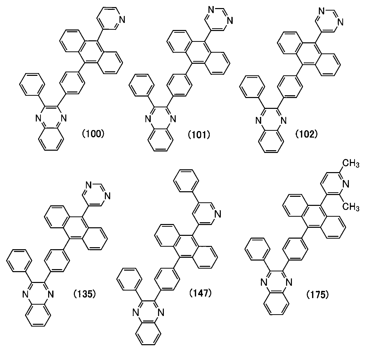


Applications Claiming Priority (3)
| Application Number | Priority Date | Filing Date | Title |
|---|---|---|---|
| JP2019055331 | 2019-03-22 | ||
| JP2019-055331 | 2019-03-22 | ||
| PCT/IB2020/052075 WO2020194097A1 (en) | 2019-03-22 | 2020-03-11 | Organic compound, light-emitting device, light-emitting apparatus, electronic device, and lighting device |
Publications (1)
| Publication Number | Publication Date |
|---|---|
| DE112020001394T5 true DE112020001394T5 (en) | 2021-12-02 |
Family
ID=72609888
Family Applications (1)
| Application Number | Title | Priority Date | Filing Date |
|---|---|---|---|
| DE112020001394.4T Pending DE112020001394T5 (en) | 2019-03-22 | 2020-03-11 | Organic compound, light-emitting device, light-emitting device, electronic device and lighting device |
Country Status (7)
| Country | Link |
|---|---|
| US (2) | US12295260B2 (en) |
| JP (2) | JP7511365B2 (en) |
| KR (1) | KR20210141528A (en) |
| CN (1) | CN113631550A (en) |
| DE (1) | DE112020001394T5 (en) |
| TW (2) | TWI851685B (en) |
| WO (1) | WO2020194097A1 (en) |
Families Citing this family (2)
| Publication number | Priority date | Publication date | Assignee | Title |
|---|---|---|---|---|
| CN115280536A (en) * | 2020-03-18 | 2022-11-01 | 株式会社半导体能源研究所 | Light-emitting device, light-emitting apparatus, electronic apparatus, and lighting apparatus |
| CN117343078A (en) | 2021-11-25 | 2024-01-05 | 北京夏禾科技有限公司 | Organic electroluminescent materials and devices |
Citations (1)
| Publication number | Priority date | Publication date | Assignee | Title |
|---|---|---|---|---|
| JP2019055331A (en) | 2015-04-10 | 2019-04-11 | 株式会社ダイセル | Syringe |
Family Cites Families (27)
| Publication number | Priority date | Publication date | Assignee | Title |
|---|---|---|---|---|
| US5077142A (en) | 1989-04-20 | 1991-12-31 | Ricoh Company, Ltd. | Electroluminescent devices |
| JP3451680B2 (en) | 1993-11-15 | 2003-09-29 | 三菱化学株式会社 | Organic electroluminescent device |
| KR100858065B1 (en) | 1999-09-22 | 2008-09-10 | 코닌클리케 필립스 일렉트로닉스 엔.브이. | Light emitting device and method for manufacturing and testing the same |
| JP2003040873A (en) | 2001-07-25 | 2003-02-13 | Idemitsu Kosan Co Ltd | Novel quinoxaline derivative and organic electroluminescent device using the same |
| KR20040081454A (en) | 2002-01-18 | 2004-09-21 | 히로세 엔지니어링 가부시키가이샤 | White light emitting compound, white light emission illuminator, and white light emission ogranic el device |
| JP4646494B2 (en) * | 2002-04-11 | 2011-03-09 | 出光興産株式会社 | Novel nitrogen-containing heterocyclic derivative and organic electroluminescence device using the same |
| JP2004200162A (en) | 2002-12-05 | 2004-07-15 | Toray Ind Inc | Light emitting element |
| JPWO2004074399A1 (en) | 2003-02-20 | 2006-06-01 | 出光興産株式会社 | Material for organic electroluminescence device and organic electroluminescence device using the same |
| KR20060004936A (en) | 2003-04-18 | 2006-01-16 | 가부시키가이샤 한도오따이 에네루기 켄큐쇼 | Quinoxaline derivatives, and organic semiconductor devices, electroluminescent devices and electronic devices using the same |
| CN1926647B (en) | 2004-02-06 | 2010-04-14 | 国立大学法人山口大学 | Electrode for energy storage device and manufacturing method thereof |
| TW200541401A (en) | 2004-02-13 | 2005-12-16 | Idemitsu Kosan Co | Organic electroluminescent device |
| JP4637651B2 (en) | 2004-06-03 | 2011-02-23 | 三井化学株式会社 | Amine compound and organic electroluminescence device containing the amine compound |
| US7951470B2 (en) | 2004-08-23 | 2011-05-31 | Semiconductor Energy Laboratory Co., Ltd. | Light emitting element, light emitting device, and lighting system |
| US20060194076A1 (en) | 2005-02-28 | 2006-08-31 | Fuji Photo Film Co., Ltd. | Organic electroluminescent element |
| WO2008047589A1 (en) | 2006-10-06 | 2008-04-24 | Semiconductor Energy Laboratory Co., Ltd. | Quinoxaline derivative, and light-emitting element and light-emitting device using quinoxaline derivative |
| JP5220377B2 (en) | 2006-10-06 | 2013-06-26 | 株式会社半導体エネルギー研究所 | Quinoxaline derivative, and light emitting element and light emitting device using quinoxaline derivative |
| JP4979333B2 (en) | 2006-10-13 | 2012-07-18 | 三井化学株式会社 | Anthracene compound and organic electroluminescence device containing the compound |
| US8119259B2 (en) | 2007-11-30 | 2012-02-21 | Semiconductor Energy Laboratory Co., Ltd. | Quinoxaline derivative, and light-emitting element and electronic device using the same |
| US8314101B2 (en) | 2007-11-30 | 2012-11-20 | Semiconductor Energy Laboratory Co., Ltd. | Quinoxaline derivative, and light-emitting element, light-emitting device, and electronic device using quinoxaline derivative |
| KR101564762B1 (en) | 2007-11-30 | 2015-10-30 | 가부시키가이샤 한도오따이 에네루기 켄큐쇼 | Light emitting device, light emitting device and electronic device using quinoxaline derivative and quinoxaline derivative |
| US8815412B2 (en) | 2007-12-21 | 2014-08-26 | Semiconductor Energy Laboratory Co., Ltd. | Quinoxaline derivative, and light-emitting element, light-emitting device, and electronic appliance using the quinoxaline derivative |
| EP2352725A1 (en) | 2008-11-07 | 2011-08-10 | Wyeth LLC | Quinoxaline-based lxr modulators |
| DE102009053191A1 (en) | 2009-11-06 | 2011-05-12 | Merck Patent Gmbh | Materials for electronic devices |
| DE102010013806B4 (en) | 2010-04-03 | 2021-06-10 | Merck Patent Gmbh | Materials for organic electroluminescent devices |
| JP6301729B2 (en) * | 2013-05-21 | 2018-03-28 | 保土谷化学工業株式会社 | Compound having indoloquinoxaline ring structure and organic electroluminescence device |
| KR102606275B1 (en) * | 2015-10-27 | 2023-12-05 | 삼성디스플레이 주식회사 | Organic light emitting device |
| JP6662049B2 (en) * | 2016-01-12 | 2020-03-11 | 凸版印刷株式会社 | Organic electroluminescence device |
-
2020
- 2020-03-11 DE DE112020001394.4T patent/DE112020001394T5/en active Pending
- 2020-03-11 KR KR1020217030896A patent/KR20210141528A/en active Pending
- 2020-03-11 CN CN202080022437.9A patent/CN113631550A/en active Pending
- 2020-03-11 WO PCT/IB2020/052075 patent/WO2020194097A1/en not_active Ceased
- 2020-03-11 US US17/439,527 patent/US12295260B2/en active Active
- 2020-03-18 TW TW109108925A patent/TWI851685B/en active
- 2020-03-18 TW TW113127267A patent/TW202506659A/en unknown
- 2020-03-19 JP JP2020049259A patent/JP7511365B2/en active Active
-
2024
- 2024-06-25 JP JP2024101911A patent/JP2024133525A/en active Pending
-
2025
- 2025-01-16 US US19/024,277 patent/US20250160203A1/en active Pending
Patent Citations (1)
| Publication number | Priority date | Publication date | Assignee | Title |
|---|---|---|---|---|
| JP2019055331A (en) | 2015-04-10 | 2019-04-11 | 株式会社ダイセル | Syringe |
Also Published As
| Publication number | Publication date |
|---|---|
| US20220158100A1 (en) | 2022-05-19 |
| JP7511365B2 (en) | 2024-07-05 |
| TW202100519A (en) | 2021-01-01 |
| CN113631550A (en) | 2021-11-09 |
| TW202506659A (en) | 2025-02-16 |
| WO2020194097A1 (en) | 2020-10-01 |
| JP2024133525A (en) | 2024-10-02 |
| TWI851685B (en) | 2024-08-11 |
| JP2020158497A (en) | 2020-10-01 |
| US12295260B2 (en) | 2025-05-06 |
| KR20210141528A (en) | 2021-11-23 |
| US20250160203A1 (en) | 2025-05-15 |
Similar Documents
| Publication | Publication Date | Title |
|---|---|---|
| DE112019007697B4 (en) | light-emitting device, light-emitting device, electronic device and lighting device | |
| DE112016007599B4 (en) | Light-emitting element, display device, electronic device and lighting device | |
| DE102020117123A1 (en) | MATERIAL FOR HOLE TRANSPORT LAYER, MATERIAL FOR HOLE INJECTION LAYER, ORGANIC COMPOUND, LIGHT EMITTING DEVICE, LIGHT EMITTING DEVICE, ELECTRONIC DEVICE AND LIGHTING DEVICE | |
| DE112016003313T5 (en) | Light-emitting element, display device, electronic device and lighting device | |
| DE112018005320T5 (en) | Organic compound, light emitting element, light emitting device, electronic device and lighting device | |
| DE102016214546A1 (en) | Organic compound, light-emitting element, light-emitting device, electronic device and lighting device | |
| DE112017002347T5 (en) | Light-emitting element, display device, electronic device and lighting device | |
| KR102850881B1 (en) | Heterocyclic compound, light-emitting element, light-emitting device, electronic device, and lighting device | |
| DE102016211086B4 (en) | Heterocyclic compound and its use, as well as light-emitting element and its use | |
| DE102021107060A1 (en) | Arylamine compound, material for hole transport layer, material for hole injection layer, light-emitting device, light-emitting device, electronic device and lighting device | |
| DE112019004580T5 (en) | Light emitting device, light emitting device, electronic device and lighting device | |
| DE112018004962T5 (en) | Light emitting element, display device, electronic device and lighting device | |
| DE112021004268T5 (en) | Light emitting device, light emitting device, display device, electronic device and lighting device | |
| DE102021133839A1 (en) | Organic semiconductor device, organic EL device, photodiode sensor, display device, light emitting device, electronic device and lighting device | |
| US20250160203A1 (en) | Organic Compound, Light-Emitting Device, Light-Emitting Apparatus, Electronic Device, and Lighting Device | |
| DE102020115542A1 (en) | Light-emitting device, light-emitting device, electronic device and lighting device | |
| DE102020122459A1 (en) | Connection, light emitting device, light emitting device, electronic device and lighting device | |
| DE102020118101A1 (en) | Organic compound, light-emitting device, light-receiving device, light-emitting device, light-emitting module, electronic device and lighting device | |
| DE112018000748B4 (en) | Organic compound, light-emitting element, light-emitting device, electronic device, and lighting device | |
| DE112021003575T5 (en) | Light-emitting device, light-emitting device, electronic device, and lighting device | |
| DE102020135111A1 (en) | Organometallic complex, top emission light-emitting material, light-emitting device, light-emitting device, electronic device and lighting device | |
| DE112020000101T5 (en) | Anthracene compound for host material, light-emitting device, light-emitting device, electronic device and lighting device | |
| DE102019200635A1 (en) | Organic compound, light-emitting element, light-emitting device, electronic device and lighting device | |
| DE102020117591A1 (en) | Organic compound, light-emitting device, light-emitting device, electronic device and lighting device | |
| DE102020134845A1 (en) | Connection, light emitting device, light emitting device, electronic device and lighting device |
Legal Events
| Date | Code | Title | Description |
|---|---|---|---|
| R012 | Request for examination validly filed | ||
| R016 | Response to examination communication |