DE112019007813T5 - Structure of an endoscope - Google Patents
Structure of an endoscope Download PDFInfo
- Publication number
- DE112019007813T5 DE112019007813T5 DE112019007813.5T DE112019007813T DE112019007813T5 DE 112019007813 T5 DE112019007813 T5 DE 112019007813T5 DE 112019007813 T DE112019007813 T DE 112019007813T DE 112019007813 T5 DE112019007813 T5 DE 112019007813T5
- Authority
- DE
- Germany
- Prior art keywords
- connecting tube
- tube
- layers
- structure according
- pull wires
- Prior art date
- Legal status (The legal status is an assumption and is not a legal conclusion. Google has not performed a legal analysis and makes no representation as to the accuracy of the status listed.)
- Withdrawn
Links
- 238000005452 bending Methods 0.000 claims abstract description 14
- 239000000463 material Substances 0.000 claims description 35
- 230000002787 reinforcement Effects 0.000 claims description 18
- 238000009954 braiding Methods 0.000 claims description 14
- 230000003014 reinforcing effect Effects 0.000 claims description 13
- 239000004677 Nylon Substances 0.000 claims description 8
- 229920001778 nylon Polymers 0.000 claims description 8
- 239000013536 elastomeric material Substances 0.000 claims description 4
- 239000000758 substrate Substances 0.000 claims description 4
- 238000009434 installation Methods 0.000 claims description 3
- 238000003780 insertion Methods 0.000 claims description 2
- 230000037431 insertion Effects 0.000 claims description 2
- 229920001343 polytetrafluoroethylene Polymers 0.000 claims description 2
- 239000004810 polytetrafluoroethylene Substances 0.000 claims description 2
- 230000001105 regulatory effect Effects 0.000 claims 1
- 239000000523 sample Substances 0.000 description 10
- 238000000034 method Methods 0.000 description 8
- 238000003384 imaging method Methods 0.000 description 7
- 210000000056 organ Anatomy 0.000 description 6
- 230000007704 transition Effects 0.000 description 6
- 229920001971 elastomer Polymers 0.000 description 3
- 239000000806 elastomer Substances 0.000 description 3
- 229910001220 stainless steel Inorganic materials 0.000 description 3
- 239000010935 stainless steel Substances 0.000 description 3
- 229920011934 Pebax® 6333 SA 01 Polymers 0.000 description 2
- 229920007373 Pebax® 7233 SA 01 Polymers 0.000 description 2
- -1 Polytetrafluorethylen Polymers 0.000 description 2
- 238000005516 engineering process Methods 0.000 description 2
- 238000004519 manufacturing process Methods 0.000 description 2
- 238000004088 simulation Methods 0.000 description 2
- 238000012360 testing method Methods 0.000 description 2
- 238000003466 welding Methods 0.000 description 2
- BUHVIAUBTBOHAG-FOYDDCNASA-N (2r,3r,4s,5r)-2-[6-[[2-(3,5-dimethoxyphenyl)-2-(2-methylphenyl)ethyl]amino]purin-9-yl]-5-(hydroxymethyl)oxolane-3,4-diol Chemical compound COC1=CC(OC)=CC(C(CNC=2C=3N=CN(C=3N=CN=2)[C@H]2[C@@H]([C@H](O)[C@@H](CO)O2)O)C=2C(=CC=CC=2)C)=C1 BUHVIAUBTBOHAG-FOYDDCNASA-N 0.000 description 1
- 241000209035 Ilex Species 0.000 description 1
- 229920009026 Pebax® 5533 SA 01 Polymers 0.000 description 1
- 229920002614 Polyether block amide Polymers 0.000 description 1
- 230000009286 beneficial effect Effects 0.000 description 1
- 230000005540 biological transmission Effects 0.000 description 1
- 230000003247 decreasing effect Effects 0.000 description 1
- 238000011161 development Methods 0.000 description 1
- 238000010586 diagram Methods 0.000 description 1
- 230000002349 favourable effect Effects 0.000 description 1
- 239000003292 glue Substances 0.000 description 1
- 230000003902 lesion Effects 0.000 description 1
- 229940127554 medical product Drugs 0.000 description 1
- 238000012545 processing Methods 0.000 description 1
- 239000011347 resin Substances 0.000 description 1
- 229920005989 resin Polymers 0.000 description 1
- 238000001356 surgical procedure Methods 0.000 description 1
Images


Classifications
-
- A—HUMAN NECESSITIES
- A61—MEDICAL OR VETERINARY SCIENCE; HYGIENE
- A61B—DIAGNOSIS; SURGERY; IDENTIFICATION
- A61B1/00—Instruments for performing medical examinations of the interior of cavities or tubes of the body by visual or photographical inspection, e.g. endoscopes; Illuminating arrangements therefor
- A61B1/005—Flexible endoscopes
-
- A—HUMAN NECESSITIES
- A61—MEDICAL OR VETERINARY SCIENCE; HYGIENE
- A61B—DIAGNOSIS; SURGERY; IDENTIFICATION
- A61B1/00—Instruments for performing medical examinations of the interior of cavities or tubes of the body by visual or photographical inspection, e.g. endoscopes; Illuminating arrangements therefor
- A61B1/00064—Constructional details of the endoscope body
- A61B1/00071—Insertion part of the endoscope body
- A61B1/00078—Insertion part of the endoscope body with stiffening means
-
- A—HUMAN NECESSITIES
- A61—MEDICAL OR VETERINARY SCIENCE; HYGIENE
- A61B—DIAGNOSIS; SURGERY; IDENTIFICATION
- A61B1/00—Instruments for performing medical examinations of the interior of cavities or tubes of the body by visual or photographical inspection, e.g. endoscopes; Illuminating arrangements therefor
- A61B1/00112—Connection or coupling means
- A61B1/00119—Tubes or pipes in or with an endoscope
-
- A—HUMAN NECESSITIES
- A61—MEDICAL OR VETERINARY SCIENCE; HYGIENE
- A61B—DIAGNOSIS; SURGERY; IDENTIFICATION
- A61B1/00—Instruments for performing medical examinations of the interior of cavities or tubes of the body by visual or photographical inspection, e.g. endoscopes; Illuminating arrangements therefor
- A61B1/005—Flexible endoscopes
- A61B1/0051—Flexible endoscopes with controlled bending of insertion part
- A61B1/0055—Constructional details of insertion parts, e.g. vertebral elements
-
- A—HUMAN NECESSITIES
- A61—MEDICAL OR VETERINARY SCIENCE; HYGIENE
- A61B—DIAGNOSIS; SURGERY; IDENTIFICATION
- A61B1/00—Instruments for performing medical examinations of the interior of cavities or tubes of the body by visual or photographical inspection, e.g. endoscopes; Illuminating arrangements therefor
- A61B1/005—Flexible endoscopes
- A61B1/0051—Flexible endoscopes with controlled bending of insertion part
- A61B1/0057—Constructional details of force transmission elements, e.g. control wires
-
- A—HUMAN NECESSITIES
- A61—MEDICAL OR VETERINARY SCIENCE; HYGIENE
- A61B—DIAGNOSIS; SURGERY; IDENTIFICATION
- A61B1/00—Instruments for performing medical examinations of the interior of cavities or tubes of the body by visual or photographical inspection, e.g. endoscopes; Illuminating arrangements therefor
- A61B1/04—Instruments for performing medical examinations of the interior of cavities or tubes of the body by visual or photographical inspection, e.g. endoscopes; Illuminating arrangements therefor combined with photographic or television appliances
Landscapes
- Health & Medical Sciences (AREA)
- Life Sciences & Earth Sciences (AREA)
- Surgery (AREA)
- Biomedical Technology (AREA)
- Medical Informatics (AREA)
- Optics & Photonics (AREA)
- Pathology (AREA)
- Radiology & Medical Imaging (AREA)
- Biophysics (AREA)
- Engineering & Computer Science (AREA)
- Physics & Mathematics (AREA)
- Heart & Thoracic Surgery (AREA)
- Nuclear Medicine, Radiotherapy & Molecular Imaging (AREA)
- Molecular Biology (AREA)
- Animal Behavior & Ethology (AREA)
- General Health & Medical Sciences (AREA)
- Public Health (AREA)
- Veterinary Medicine (AREA)
- Endoscopes (AREA)
- Instruments For Viewing The Inside Of Hollow Bodies (AREA)
- Rigid Pipes And Flexible Pipes (AREA)
Abstract
Die vorliegende Erfindung bezieht sich auf das Gebiet der medizinischen Geräte und beschreibt eine Endoskopstruktur, welche aus einem Befestigungsring, einem Verbindungsrohr und einem Einsatzrohr besteht, die hintereinander angeordnet sind, wobei das Verbindungsrohr aus geflochtenen Schichten besteht, das Verbindungsrohr gebogen werden kann und die Steifigkeit der geflochtenen Schichten des Verbindungsrohrs umgekehrt proportional zum maximalen Biegewinkel des Verbindungsrohrs ist; die Struktur besteht zudem aus Zugdrähten. Die Zugdrähte sind durch das Verbindungsrohr hindurch am Befestigungsring des Einsatzes befestigt, und das Verbindungsrohr wird durch Zug an den Zugdrähten am Ende des Einsatzrohrs gebogen. Die wesentlichen Vorteile der vorliegenden Erfindung sind: die geflochtenen Schichten und die Zugdrähte sind innerhalb des Verbindungsrohrs angeordnet, so dass die vorliegende Erfindung die Vorteile einer bequemen Verbindung, Weichheit und Steuerbarkeit aufweist; die Führungsnut ist an den äußeren Seitenwänden der Trägerschichten angeordnet, die Zugdrähte sind jeweils innerhalb der Führungsnut platziert, bei der Bewegung der Zugdrähte spielt die Führungsnut eine Rolle der Führung und Positionierung, um zu gewährleisten, dass sich die Zugdrähte nur entlang der Längsrichtung der Struktur bewegen.The present invention relates to the field of medical devices and describes an endoscope structure which consists of a fixing ring, a connecting tube and an insert tube arranged in series, wherein the connecting tube is made of braided layers, the connecting tube can be bent and the rigidity of the braided layers of the connecting pipe is inversely proportional to the maximum bending angle of the connecting pipe; the structure also consists of pull wires. The puller wires are attached to the liner's attachment ring through the connector tube, and the connector tube is bent by pulling on the puller wires at the end of the liner tube. The main advantages of the present invention are: the braided layers and the pull wires are placed inside the connecting tube, so the present invention has the advantages of convenient connection, softness and controllability; the guide groove is located on the outer side walls of the support layers, the puller wires are each placed inside the guide groove, in the movement of the puller wires, the guide groove plays a role of guiding and positioning to ensure that the puller wires only move along the longitudinal direction of the structure .
Description
Technischer BereichTechnical part
Die vorliegende Erfindung bezieht sich auf das Gebiet der medizinischen Geräte und hier insbesondere auf die Struktur eines Endoskops.The present invention relates to the field of medical devices and more particularly to the structure of an endoscope.
Hintergrund-Technologiebackground technology
Mit der kontinuierlichen Entwicklung von Technologien hat das medizinische Endoskop weite Verbreitung im medizinischen Bereich gefunden, und das Endoskop ist ein wichtiges Gerät zur Erkennung von Organ- und Gewebeläsionen.With the continuous development of technologies, the medical endoscope has been widely used in the medical field, and the endoscope is an important device for detecting organ and tissue lesions.
Ein Endoskop besteht im Wesentlichen aus einem Verbindungsrohr, einer mit dem Verbindungsrohr verbundenen Sonde und einem Antriebsmechanismus, durch den die Sonde in den erforderlichen Winkeln gebogen werden kann; die Zugdrähte des Antriebsmechanismus sind mit dem Bedienungsende des Verbindungsrohrs verbunden. Die Sonde, welche am Ende des Verbindungsrohrs angebracht ist, wird in den menschlichen Körper eingeführt, es werden Bilder von den Organen und Geweben um die Sonde herum gesammelt und auf ein externes Display übertragen, sodass das medizinische Personal diese betrachten kann.An endoscope basically consists of a connecting tube, a probe connected to the connecting tube, and a drive mechanism that allows the probe to be bent to the required angles; the drive mechanism pull wires are connected to the operating end of the connecting tube. The probe attached to the end of the connecting tube is inserted into the human body, images of the organs and tissues around the probe are collected and transmitted to an external display for medical staff to view.
Gegenwärtig sind zwei Arten von Ureteroskopen in Gebrauch: starre und flexible Ureteroskope. Ein starres Ureteroskop bietet die Vorteile einer guten Richtwirkung und einer einfachen Bedienung und Platzierung, lässt sich jedoch nicht biegen und führt zu blinden Sicht- und Operationsbereichen. Ein flexibles Ureteroskop hingegen vermeidet blinde Sicht- und Operationsbereiche, weist jedoch die Nachteile einer weichen Verbindungsrohrstruktur, einer schlechten Kontrollierbarkeit, einer erschwerten Bedienung, eines hohen Preises und die Gefahr auf, leicht beschädigt zu werden.Two types of ureteroscopes are currently in use: rigid and flexible ureteroscopes. A rigid ureteroscope offers the advantages of good directivity and ease of use and placement, but does not flex and results in blind areas of vision and surgery. A flexible ureteroscope, on the other hand, avoids blind vision and operation areas, but has the disadvantages of soft connecting tube structure, poor controllability, difficult operation, high price and risk of being easily damaged.
Durch eine Patentrecherche wurde festgestellt, dass in der offenen Literatur
Zusammenfassungsummary
Ziel der vorliegenden Erfindung ist es, eine Endoskopstruktur zu entwickeln, um die oben genannten Probleme zu lösen.The object of the present invention is to develop an endoscope structure to solve the above problems.
Das technische Schema der vorliegenden Erfindung zum Erreichen des oben genannten Ziels ist eine Endoskopstruktur zu schaffen, welche aus einem Befestigungsring, einem Verbindungsrohr und einem Bedienungsrohr besteht, die nacheinander verbunden sind, wobei das Verbindungsrohr aus geflochtenen Schichten besteht, das Verbindungsrohr sich biegen lässt und die Steifigkeit der geflochtenen Schichten des Verbindungsrohrs sich umgekehrt proportional zu dem maximalen Biegewinkel des Verbindungsrohrs verhält;The technical scheme of the present invention to achieve the above object is to create an endoscope structure, which consists of a fixing ring, a connecting tube and an operating tube, which are sequentially connected, wherein the connecting tube is made of braided layers, the connecting tube can be bent and the Stiffness of the braided layers of the connecting pipe is inversely proportional to the maximum bending angle of the connecting pipe;
Die Struktur besteht zudem aus Zugdrähten. Diese Zugdrähte werden über das Verbindungsrohr am Befestigungsring durch das Betätigungsrohr fixiert, das Verbindungsrohr wird durch Zug an den Zugdrähten am Ende des Betätigungsrohrs gebogen.The structure also consists of pull wires. These pull wires are fixed via the connecting tube on the fastening ring through the operating tube, the connecting tube is bent by pulling on the pull wires at the end of the operating tube.
Das Verbindungsrohr ist ein Hohlrohr, das aus mehreren Materialschichten zusammengesetzt ist. Die innerste Schicht des Verbindungsrohrs bildet eine Stützschicht, die Stützschichten sind aus einem Stück geformt, die Flechtschichten sind an den äußeren Seitenwänden der Stützschichten angebracht und sind mit den gleichen oder unterschiedlichen Flechtgarnen umwickelt.The connecting tube is a hollow tube composed of several layers of material. The innermost layer of the connecting tube forms a support layer, the support layers are molded in one piece, the braid layers are attached to the outer side walls of the support layers and are wrapped with the same or different braid yarns.
Der Außendurchmesser des Verbindungsrohrs ist größer als derjenige des Befestigungsrings, zwischen dem Führungskopf und der Trägerschicht ist eine Positionierungsstufe ausgebildet, und das dem Verbindungsrohr zugewandte Ende der Verstärkungsschicht hat Kontakt mit der Positionierungsstufe.The outer diameter of the connecting tube is larger than that of the fixing ring, a positioning step is formed between the guide head and the support layer, and the end of the reinforcing layer facing the connecting tube is in contact with the positioning step.
An der Außenwand der Trägerschicht ist eine den Zugdrähten entsprechende Führungsnut vorhanden, die Zugdrähte sind in der Führungsnut angeordnet und können darin frei gleiten. Die Führungsnut ist symmetrisch zu den Mittelachsen der Trägerschichten angeordnet.A guide groove corresponding to the pull wires is provided on the outer wall of the support layer, the pull wires are arranged in the guide groove and can slide freely therein. The guide groove is arranged symmetrically to the central axes of the carrier layers.
Das Verbindungsrohr besteht aus mindestens zwei miteinander verbundenen Abschnitten mit unterschiedlicher Steifigkeit, der Abschnitt in der Nähe des Bedienungsrohrs ist steifer als der Abschnitt in der Nähe des Befestigungsrings. Die Steifigkeit der Abschnitte lässt sich durch Änderung der Steifigkeit der geflochtenen Schichten im Inneren dieser Abschnitte regulieren, die Stützschichten in den einzelnen Abschnitten sind aus demselben flexiblen und verformbaren Material hergestellt und das flexible und verformbare Material kann aus PTFE bestehen.The connecting tube consists of at least two sections connected to each other with different rigidity, the section near the operating tube is stiffer than the section near the mounting ring. The stiffness of the sections can be adjusted by changing the stiffness of the braided layers inside these sections, the support layers in each section are made of the same flexible and deformable material and the flexible and deformable material can be made of PTFE.
Die Anzahl der Zugdrähte beträgt mindestens zwei, ein Ende der Zugdrähte ist an der Seitenwand des Befestigungsrings angebracht, die anderen Enden verlaufen außerhalb des Endes des Betriebsrohrs entlang der Wand des Verbindungsrohrs. Sobald einer der Zugdrähte gezogen wird, biegt sich das Verbindungsrohr in Richtung des gebogenen Zugdrahts.The number of puller wires is at least two, one end of the puller wires is attached to the side wall of the mounting ring, the other ends pass outside the end of the operating pipe along the wall of the connecting pipe. As soon as one of the puller wires is pulled, the connecting tube bends in the direction of the bent puller wire.
Das Verbindungsrohr besteht ebenfalls aus Hülsen aus Nylon-Elastomer-Material, wobei die Hülsen so angeordnet sind, dass sie auf die Außenwände der geflochtenen Schichten passen, ein Führungskopf, der zum Verbinden mit dem Kameraobjektiv verwendet wird, ist am Ende des Befestigungsrings angebracht, und eine Kerbe, welche die feste Installation des Kameraobjektivs ermöglicht, ist am Führungskopf angebracht.The connection tube is also made up of sleeves made of nylon elastomeric material, the sleeves being arranged to fit onto the outer walls of the braided layers, a guide head used to connect to the camera lens is attached to the end of the mounting ring, and a notch that allows for the fixed installation of the camera lens is provided on the guide head.
Die Kerbe ist vorzugsweise als U-förmige Kerbe ausgebildet, ein Verstärkungsmantel, welcher die gleich geformt ist wie der Führungskopf, ist umhüllt und außerhalb des Führungskopfes angebracht, um die Stabilität des Führungskopfes zu erhöhen.The notch is preferably formed as a U-shaped notch, a reinforcing jacket, which is the same shape as the guide head, is wrapped and attached outside the guide head to increase the stability of the guide head.
Ein Verstärkungsabschnitt ist an einem Ende des Verstärkungsmantels im Bereich der Hülse angeordnet, wobei der Verstärkungsmantel teilweise in den Verstärkungsabschnitt eingebettet ist.A reinforcement section is arranged at one end of the reinforcement jacket in the region of the sleeve, the reinforcement jacket being partially embedded in the reinforcement section.
Die vorteilhaften Effekte sind, dass 1. die geflochtenen Schichten und Zugdrähte im Inneren des Verbindungsrohrs liegen, so dass die vorliegende Erfindung die Vorteile einer komfortablen Verbindung, die weich und kontrollierbar ist, aufweist. Darunter haben die geflochtenen Schichten eine gewisse Biegesteifigkeit, so dass die Gesamtfestigkeit des Verbindungsrohrs gesteigert werden kann und eine erschwerte Verbindung aufgrund des weichen Rohrs ausgeschlossen werden kann; die Biegerichtung des Verbindungsrohrs kann durch Ziehen des Zugdrahts gesteuert werden, die Kamerasonde, welche an der Spitze des Verbindungsrohrs angebracht ist, kann so gesteuert werden, dass sie die gewünschten Positionen in Übereinstimmung mit den Anforderungen erreicht. Somit weist die vorliegende Erfindung die Vorteile einer guten Richtwirkung und einer bequemen Steuerung auf.The beneficial effects are that 1. The braided layers and pull wires are inside the connecting tube, so the present invention has the advantages of a comfortable connection that is soft and controllable. Among them, the braided layers have a certain flexural rigidity, so that the overall strength of the connection pipe can be increased and difficult connection due to the soft pipe can be eliminated; the bending direction of the connecting pipe can be controlled by pulling the pull wire, the camera probe attached to the tip of the connecting pipe can be controlled to reach the desired positions according to the needs. Thus, the present invention has the advantages of good directivity and convenient control.
2. Die Führungsnut ist an den äußeren Seitenwänden der Trägerschichten angeordnet, die Zugdrähte sind jeweils in der Führungsnut untergebracht. Bei der Bewegung der Zugdrähte spielt die Führungsnut eine Rolle bei der Führung und Positionierung, damit sichergestellt ist, dass sich die Zugdrähte nur entlang der Längsrichtung der Struktur bewegen, eine genaue Kontrolle der Gesamtbiegerichtung durch die Steuerung der Zugdrähte möglich ist und eine insgesamt bessere Stabilität erreicht werden kann.2. The guide groove is arranged on the outer side walls of the carrier layers, the puller wires are each accommodated in the guide groove. In the movement of the puller wires, the guide groove plays a role in guiding and positioning to ensure that the puller wires move only along the longitudinal direction of the structure, accurate control of the overall bending direction through the control of the puller wires, and achieve better overall stability can be.
Die vorliegende Erfindung basiert auf einer integralen Struktur, die aus einem Befestigungsring, einem Verbindungsrohr und einem Betätigungsrohr besteht. Das Verbindungsrohr besteht hauptsächlich aus Stützschichten und geflochtenen Schichten, hat geringe Materialkosten, eine einfache Struktur und niedrige Gesamtproduktionskosten und ermöglicht als medizinisches Einwegprodukt eine erhebliche Reduzierung der medizinischen Kosten.The present invention is based on an integral structure consisting of a mounting ring, a connecting tube and an actuating tube. The connecting tube is mainly composed of supporting layers and braided layers, has low material costs, simple structure and low overall production costs, and as a disposable medical product, it enables medical costs to be significantly reduced.
Figurenlistecharacter list
-
-
-
-
-
-
Beschreibung der AusführungsformenDescription of the embodiments
Um es deutlich auszudrücken, die ursprüngliche Absicht der vorliegenden Erfindung ist es, die folgenden Nachteile der gegenwärtigen medizinischen Endoskope, insbesondere der Nierenendoskope, zu beseitigen: starre Ureteroskope lassen sich nur schwer biegen und führen zu blinden Bereichen der Sicht und des Einsatzes, flexible Ureteroskope sind zu weich, nicht für den Einsatz geeignet und teuer. Die vorliegende Erfindung zielt darauf ab, eine neue medizinische Endoskopstruktur anzubieten, die sowohl die Vorteile der starren als auch der flexiblen Ureteroskope in sich vereint.To be clear, the original intent of the present invention is to eliminate the following disadvantages of current medical endoscopes, particularly renal endoscopes: Rigid ureteroscopes are difficult to bend and result in blind areas of vision and use that flexible ureteroscopes are too soft, not suitable for use and expensive. The present invention aims to offer a new medical endoscope structure that combines the advantages of both rigid and flexible ureteroscopes.
Die vorliegende Erfindung wird im Folgenden durch die Zusammenfassung der
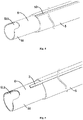
Der Kernmechanismus der Endoskopstruktur, welcher in dem vorliegenden Erfindungspatent definiert wird, umfasst zwei Aspekte: eine geflochtene Schicht 3 wird zwischen den Schichten eines Verbindungsrohrs 1 eingefügt, damit das Verbindungsrohr 1 eine gewisse Steifigkeit erhält und das flexible Ureteroskop nicht zu weich wird; eine Zugdrahtstruktur 7 wird in dem Rohr entwickelt, sobald an den Zugdrähten 7 gezogen wird, bringen die Zugdrähte 7 den Kopf der Struktur dazu, sich zu biegen, so dass die Bewegungsrichtung der Struktur am Ende der Struktur (außerhalb des menschlichen Körpers) gesteuert werden kann und so der Nachteil des starren Ureteroskops, welches sich nur schwer biegen lässt, vermieden werden kann.The core mechanism of the endoscope structure, which is defined in the present invention patent, includes two aspects: a
Die auf den beiden oben genannten Aspekten basierende Struktur wird im Folgenden vollständig beschrieben:
- 1. Beschreibung der Struktur und des Prinzips der geflochtenen Schichten 3.
- 1. Description of the structure and principle of braided layers 3.
Wie in
Das Verbindungsrohr 1 ist ein Zwischenrohr, das die Kameralinse und den Bedienungsgriff verbindet und aus mehreren Materialschichten besteht. Als eine dieser Schichten können die geflochtenen Schichten 3 mit demselben oder unterschiedlichen Flechtgarnen geflochten und verzwirnt werden, durch Änderung des Flechtmaterials, der Flechtmethode und der Kett- und Schussdichte des Geflechts kann die Steifigkeit der entsprechenden geflochtenen Schichten 3 bestimmt werden, die Dicken der geflochtenen Schichten 3 betragen vorzugsweise 0,025 mm - 0,03 mm. Das Flechtgarn der geflochtenen Lagen 3 kann aus einem oder mehreren der Materialien SS304, SS304V, SS304L, SS316 und SS316L bestehen, bevorzugt aus SS304V. Die Flechtmethode kann eine Flechtmethode für die Köperstruktur sein, wie z.B. 1/2 oder 3/1, die Dichte der Kett- und Schussfäden der Flechtung kann direkt mit einer Dichte gemessen werden, je höher die Kett- und Schussdichte der Flechtung ist, desto flexibler ist die geflochtene Lage 3.The connecting
Das Verbindungsrohr 1 besteht aus mindestens zwei miteinander verbundenen Abschnitten mit unterschiedlicher Steifigkeit in axialer Richtung. Alle Abschnitte sind aus demselben flexiblen und verformbaren Material hergestellt, wobei sich die Steifigkeit dieser Abschnitte vom Einsatzrohr 2 bis zum Befestigungsring 8 nacheinander verringert. In einer bevorzugten Ausführungsform, wie sie in
Beschreibung der Struktur und des Prinzips der Zugdrähte 7.Description of the structure and principle of the
Die Zugdrähte 7 sind durch das Verbindungsrohr 1 mit dem Einsatzrohr 2 an dem Befestigungsring 8 befestigt, das Verbindungsrohr 1 wird durch Zug an den Zugdrähten 7 am Ende des Einsatzrohrs 2 gebogen.The
Wie in den
Allerdings stellen die geflochtenen Schichten 3 und die Zugdrähte 7 kein vollständiges technisches Schema dar. Um die vorliegende Erfindung zu präzisieren, wird sie im Folgenden näher ausgeführt:
- Die innerste Schicht des
Verbindungsrohrs 1 ist dieStützschicht 5, die Stützschichten sind integral geformt, diegeflochtenen Schichten 3 sind an denAußenwänden der Stützschichten 5 angeordnet und passen darauf, und die geflochtenen Schichten 3 sind mit den gleichen oder unterschiedlichen Flechtgarnen geflochten.Die Trägerschichten 5 bestehen aus flexiblem und verformbarem Material; in dieser Ausführungsform besteht das flexible und verformbare Material aus Polytetrafluorethylen (PTFE). Das PTFE-Material hat die Eigenschaft eines äußerst geringen Reibungskoeffizienten, weshalb die aus dem PTFE-Material hergestellten Trägerschichten 5 sehr glatt und günstig für die Anordnung verschiedener funktioneller Rohre und Drähte in derTrägerschicht 5 sind, wie z.B. Gerätekanal, Übertragungssignalleitung und Kabel; die rohrförmigen Strukturen der Trägerschichten 5 können aus suspendiertem PTFE-Harz gefertigt und integral mit einem Extruder geformt werden, dieStärken der Trägerschichten 5 betragen 0. 12 mm ~ 0,18mm, unddie Bohrungsdurchmesser betragen
- The innermost layer of the
connection pipe 1 is thesupport layer 5, the support layers are integrally formed, the braided layers 3 are placed on and fitted to the outer walls of the support layers 5, and the braided layers 3 are braided with the same or different braiding yarns. The carrier layers 5 consist of flexible and deformable material; in this embodiment, the flexible and deformable material is polytetrafluoroethylene (PTFE). The PTFE material has the property of extremely low coefficient of friction, so thesubstrates 5 made of the PTFE material are very smooth and favorable for arranging various functional pipes and wires in thesubstrate 5, such as equipment duct, transmission signal line and cable; the tubular structures of the backing layers 5 can be made of suspended PTFE resin and integrally molded with an extruder, the thickness of the backing layers 5 are 0.12mm~0.18mm, and the bore diameters are 2.52mm~2.55mm
Das Verbindungsrohr 1 besteht ebenfalls aus Muffen 4 aus elastomerem Nylonmaterial, die Muffen 4 sind an den Außenwänden der geflochtenen Schichten 3 angeordnet und passen darauf. In dieser Ausführungsform bestehen die Muffen 4 aus elastomerem Nylonmaterial, ihr Innendurchmesser steigt entlang der Richtung vom Befestigungsring 8 zum Einsatzrohr 2 allmählich an, der Bereich dieser Innendurchmesser beträgt 2,9 mm - 3,2 mm, und die Wandstärken der Muffen 4 betragen 0,1 mm - 0,15 mm.The connecting
Wie in
Die Steifigkeitsprüfung für verschiedene Abschnitte des Verbindungsrohrs 1 verläuft wie folgt:
- Schritt I: Entnehmen Sie Proben gleicher Länge nacheinander aus verschiedenen Abschnitten des
Verbindungsrohrs 1 entlang derRichtung vom Einsatzrohr 2zum Befestigungsring 8; - Schritt II: Fixieren Sie beide Enden einer Probe, ziehen Sie den mittleren Abschnitt der Probe mit einem Spannungsmessgerät, und lesen Sie den Spannungswert ab. Je höher dieser Spannungswert ist, desto höher ist auch der Steifigkeitswert des entsprechenden Abschnitts;
- Schritt III: Passen Sie das Material der Hülse 4 und das Flechtmaterial, die Flechtmethode und die Kett- und Schussdichte der Flechtung der Flechtschicht 3 für jeden Abschnitt gemäß dem Spannungswert eines solchen Abschnitts an, um die Steifigkeit der Abschnitte entlang der Richtung vom Befestigungsring 8
zum Einsatzrohr 2 schrittweise zu reduzieren; - Schritt IV: Machen Sie einen simulierten Biegetest über
das Verbindungsrohr 1 mit einem Simulationsmodell des menschlichen Organs und ermitteln Sie schließlich die optimalen Steifigkeitswerte der einzelnen Abschnitte, indem Sie bewerten, ob die Biegegrade dieser Abschnitte das Simulationsmodell des menschlichen Organs behindern und die Voraussetzungen für den normalen Einsatz erfüllt werden können.
- Step I: Take samples of the same length sequentially from different sections of the connecting
tube 1 along the direction from theinsert tube 2 to the fixingring 8; - Step II: Fix both ends of a sample, stretch the middle section of the sample with a strain gauge and read the strain value. The higher this stress value, the higher the stiffness value of the corresponding section;
- Step III: Adjust the material of the
sleeve 4 and the braiding material, the braiding method, and the warp and weft density of the braiding of thebraiding layer 3 for each section, according to the stress value of such a section, to improve the rigidity of the sections along the direction from the fixingring 8 to the to gradually reduceinsert tube 2; - Step IV: Make a simulated bending test about the connecting
pipe 1 with a human organ simulation model, and finally find the optimal rigidity values of each section by evaluating whether the bending degrees of these sections hinder the human organ simulation model and the conditions for the normal one use can be fulfilled.
Im Folgenden werden der Montageprozess und das Funktionsprinzip der vorliegenden Erfindung beschrieben:
- Zuerst schweißen
Sie die Zugdrähte 7 auf die Seitenwand desVerstärkungsmantels 6, tragen anschließend AB-Kleber auf dieOberflächen der Zugdrähte 7 auf, richten dieZugdrähte 7 an derPosition der Kerbe 511am Führungskopf 51 aus und richten dieZugdrähte 7 an der Position des Drahtkanals 53 aus und ummanteln schließlichden Verstärkungsmantel 6 an der Außenseite desFührungskopfes 51.Sobald die Verstärkungsschicht 6 andie Positionierungsstufe 52 stößt, ist die Montage abgeschlossen. Legen Siedann die Zugdrähte 7 indie Drahtkanäle 53. Verflechten Siedie geflochtenen Schichten 3 mit dem Flechtmaterialaus dem Befestigungsring 8 und an denAußenwänden der Stützschichten 5. Führen Sie die mitden geflochtenen Schichten 3 bedeckten Stützschichten 5 in den Extruder ein, extrudieren Sie das Nylon-Elastomer-Material mit dem Extruder und formen Sie dieHülsen 4, um dieStützschichten 5 und die geflochtenen Schichten 3 fest zu umhüllen. Dann schneiden Sie das Nylon-Elastomer-Materialvon der Verstärkungsschicht 6 ab. Im Vergleich zu dem Verfahren, beidem die Zugdrähte 7 indie Trägerschichten 5 eingebettet werden,dann die Flechtschichten 3 und dieMuffen 4 geflochten werden und schließlich geschweißt wird, spart dieses Verfahren die Zeit für die mehrfache Montage und Demontage des Verbindungsrohrs 1 in und aus der Form bzw. den Werkzeugen, wodurch sich auch die Verarbeitungsschritte vereinfachen.
- First, weld the
puller wires 7 to the side wall of thereinforcement jacket 6, then apply AB glue to the surfaces of thepuller wires 7, align thepuller wires 7 with thenotch 511 position on theguide head 51, and align thepuller wires 7 with thewire duct position 53 and finally encase thereinforcement jacket 6 on the outside of theguide head 51. As soon as thereinforcement layer 6 abuts thepositioning step 52, assembly is complete. Then put the pullingwires 7 in thewire channels 53. Braid the braided layers 3 with the braiding material from thefastening ring 8 and on the outer walls of the support layers 5. Insert the support layers 5 covered with the braided layers 3 into the extruder, extrude Extrude the nylon elastomeric material and form thesleeves 4 to encase the support layers 5 andbraid layers 3 tightly. Then cut the nylon elastomer material from thereinforcement layer 6. Compared to the method of embedding thepuller wires 7 in the support layers 5, then braiding the braid layers 3 andsleeves 4, and finally welding, this method saves the time for multiple assembly and disassembly of thejoint pipe 1 in and out the mold or the tools, which also simplifies the processing steps.
Das obige technische Schema spiegelt nur das bevorzugte technische Schema des technischen Schemas der vorliegenden Erfindung wider. Die Änderungen bestimmter Aspekte des technischen Schemas, die von Fachleuten vorgenommen werden, stellen das Prinzip der vorliegenden Erfindung dar und fallen unter den Schutzbereich der vorliegenden Erfindung.The above technical scheme reflects only the preferred technical scheme of the technical scheme of the present invention. The changes of certain aspects of the technical scheme made by those skilled in the art constitute the principle of the present invention and fall within the scope of the present invention.
BezugszeichenlisteReference List
- 11
- Verbindungsrohr;connecting pipe;
- 1111
- flexibler Abschnitt;flexible section;
- 1212
- Übergangsabschnitt;transition section;
- 1313
- handgeführter Abschnitt;hand-held section;
- 22
- Bedienungsrohr;operating tube;
- 33
- geflochtene Schicht;braided layer;
- 44
- Hülse;sleeve;
- 4141
- Verstärkungsabschnitt;reinforcement section;
- 55
- Stützschicht;support layer;
- 5151
- Führungskopf;guide head;
- 511511
- Kerbe;Score;
- 5252
- Positionierungsstufe;positioning stage;
- 5353
- Drahtkanal;wire duct;
- 66
- Verstärkungsschicht;reinforcement layer;
- 77
- Zugdraht;pull wire;
- 88th
- Befestigungsring.mounting ring.
ZITATE ENTHALTEN IN DER BESCHREIBUNGQUOTES INCLUDED IN DESCRIPTION
Diese Liste der vom Anmelder aufgeführten Dokumente wurde automatisiert erzeugt und ist ausschließlich zur besseren Information des Lesers aufgenommen. Die Liste ist nicht Bestandteil der deutschen Patent- bzw. Gebrauchsmusteranmeldung. Das DPMA übernimmt keinerlei Haftung für etwaige Fehler oder Auslassungen.This list of the documents cited by the applicant was generated automatically and is included solely for the better information of the reader. The list is not part of the German patent or utility model application. The DPMA assumes no liability for any errors or omissions.
Zitierte PatentliteraturPatent Literature Cited
- CN 106963331 A [0005]CN 106963331A [0005]
Claims (10)
Applications Claiming Priority (1)
| Application Number | Priority Date | Filing Date | Title |
|---|---|---|---|
| PCT/CN2019/117816 WO2021092781A1 (en) | 2019-11-13 | 2019-11-13 | Endoscope structure |
Publications (1)
| Publication Number | Publication Date |
|---|---|
| DE112019007813T5 true DE112019007813T5 (en) | 2022-06-30 |
Family
ID=75911339
Family Applications (1)
| Application Number | Title | Priority Date | Filing Date |
|---|---|---|---|
| DE112019007813.5T Withdrawn DE112019007813T5 (en) | 2019-11-13 | 2019-11-13 | Structure of an endoscope |
Country Status (5)
| Country | Link |
|---|---|
| US (1) | US20220386851A1 (en) |
| JP (1) | JP2023503263A (en) |
| DE (1) | DE112019007813T5 (en) |
| GB (1) | GB2605709A (en) |
| WO (1) | WO2021092781A1 (en) |
Families Citing this family (3)
| Publication number | Priority date | Publication date | Assignee | Title |
|---|---|---|---|---|
| CN113647897B (en) * | 2021-09-24 | 2023-07-25 | 苏州法兰克曼医疗器械有限公司 | Gastroscope tube with changeable hardness |
| CN116035512B (en) * | 2023-01-17 | 2025-12-05 | 上海欧太医疗器械有限公司 | Bending tube device that combines metal and rubber |
| TWI844432B (en) * | 2023-07-21 | 2024-06-01 | 黃吳月 | Flexible endoscope structure |
Citations (1)
| Publication number | Priority date | Publication date | Assignee | Title |
|---|---|---|---|---|
| CN106963331A (en) | 2017-04-20 | 2017-07-21 | 珠海嘉润医用影像科技有限公司 | Airway wall |
Family Cites Families (9)
| Publication number | Priority date | Publication date | Assignee | Title |
|---|---|---|---|---|
| US20080091169A1 (en) * | 2006-05-16 | 2008-04-17 | Wayne Heideman | Steerable catheter using flat pull wires and having torque transfer layer made of braided flat wires |
| KR20110117116A (en) * | 2008-12-26 | 2011-10-26 | 스미토모 베이클리트 컴퍼니 리미티드 | Catheter |
| US8864744B2 (en) * | 2009-02-25 | 2014-10-21 | St. Jude Medical, Atrial Fibrillation Division, Inc. | Medical device having laminate-coated braid assembly |
| US10517464B2 (en) * | 2011-02-07 | 2019-12-31 | Endochoice, Inc. | Multi-element cover for a multi-camera endoscope |
| CN104958824B (en) * | 2015-07-30 | 2018-12-21 | 湖南埃普特医疗器械有限公司 | A kind of guiding catheter |
| CN108042897A (en) * | 2017-12-28 | 2018-05-18 | 南京普微森医疗科技有限公司 | A kind of composite construction conduit |
| CN208837884U (en) * | 2018-04-28 | 2019-05-10 | 苏州新光维医疗科技有限公司 | A kind of traction mechanism and endoscope |
| CN209107285U (en) * | 2018-08-08 | 2019-07-16 | 苏州新光维医疗科技有限公司 | An endoscope catheter structure |
| CN109349984A (en) * | 2018-11-09 | 2019-02-19 | 苏州新光维医疗科技有限公司 | A flexible gradient endoscope catheter with braided wire structure |
-
2019
- 2019-11-13 DE DE112019007813.5T patent/DE112019007813T5/en not_active Withdrawn
- 2019-11-13 GB GB2207248.2A patent/GB2605709A/en not_active Withdrawn
- 2019-11-13 US US17/776,260 patent/US20220386851A1/en not_active Abandoned
- 2019-11-13 JP JP2022528030A patent/JP2023503263A/en active Pending
- 2019-11-13 WO PCT/CN2019/117816 patent/WO2021092781A1/en not_active Ceased
Patent Citations (1)
| Publication number | Priority date | Publication date | Assignee | Title |
|---|---|---|---|---|
| CN106963331A (en) | 2017-04-20 | 2017-07-21 | 珠海嘉润医用影像科技有限公司 | Airway wall |
Also Published As
| Publication number | Publication date |
|---|---|
| JP2023503263A (en) | 2023-01-27 |
| US20220386851A1 (en) | 2022-12-08 |
| WO2021092781A1 (en) | 2021-05-20 |
| GB2605709A (en) | 2022-10-12 |
| GB202207248D0 (en) | 2022-06-29 |
Similar Documents
| Publication | Publication Date | Title |
|---|---|---|
| DE69215639T2 (en) | endoscope | |
| DE4013653C2 (en) | Endoscope with a guide tube assembly | |
| EP0552429B1 (en) | Endoscope with a steerable distal end portion | |
| DE3714492C2 (en) | Tubular construction for medical applications | |
| DE69732742T2 (en) | Tubular medical device | |
| DE112019007813T5 (en) | Structure of an endoscope | |
| DE4438944C2 (en) | endoscope | |
| EP2446810B1 (en) | Endoscope with adjustable view angle | |
| DE102007019779A1 (en) | Endoscope instrument channel, has flexible part attached to distal end of flexible tube, and flexible outer spiral groove running over entire length of flexible part and flexible tube | |
| DE3004335A1 (en) | FLEXIBLE LINE ARRANGEMENT FOR AN ENDOSCOPE | |
| EP1475031B1 (en) | Endoscope shaft | |
| DE2441283B2 (en) | Endoscope with outer and multilayer inner tube for treatment instruments | |
| DE102011103283A1 (en) | Surgical shaft instrument | |
| DE3008120A1 (en) | BENDING ENDOSCOPE TUBE | |
| DE4136737A1 (en) | ENDOSCOPE | |
| WO2011018249A1 (en) | Medical catheter instrument | |
| DE4102211A1 (en) | BENDING DEVICE FOR AN ENDOSCOPE | |
| DE102012201081A1 (en) | Surgical instrument | |
| DE112018000515T5 (en) | endoscope | |
| DE102012200794A1 (en) | Optical fiber with a bundle of photoconductive fibers and a method of bending the optical fiber | |
| DE102015224653A1 (en) | Adjustable probe holder assembly for a control sensor | |
| DE3916288A1 (en) | Uretero-renoscope and endoscope | |
| DE112010004961T5 (en) | Endoscope with extra-fine diameter | |
| DE3039551A1 (en) | Flexible endoscope connecting tube - comprises two sections with articulation rings bent by pull wires in fixed spirals | |
| DE4222271A1 (en) | Medical endoscope for internal examination and/or treatment - has control at proximal end to deflect distal end of at least partially flexible shaft |
Legal Events
| Date | Code | Title | Description |
|---|---|---|---|
| R012 | Request for examination validly filed | ||
| R082 | Change of representative |
Representative=s name: KARAKATSANIS, GEORGIOS, DR., DE |
|
| R119 | Application deemed withdrawn, or ip right lapsed, due to non-payment of renewal fee |