DE112014002683B4 - Adjustment method for adaptive optics system, adaptive optics system and storage medium storing a program for an adaptive optics system - Google Patents
Adjustment method for adaptive optics system, adaptive optics system and storage medium storing a program for an adaptive optics system Download PDFInfo
- Publication number
- DE112014002683B4 DE112014002683B4 DE112014002683.2T DE112014002683T DE112014002683B4 DE 112014002683 B4 DE112014002683 B4 DE 112014002683B4 DE 112014002683 T DE112014002683 T DE 112014002683T DE 112014002683 B4 DE112014002683 B4 DE 112014002683B4
- Authority
- DE
- Germany
- Prior art keywords
- light intensity
- intensity distribution
- phase
- phase pattern
- wavefront
- Prior art date
- Legal status (The legal status is an assumption and is not a legal conclusion. Google has not performed a legal analysis and makes no representation as to the accuracy of the status listed.)
- Active
Links
- 230000003044 adaptive effect Effects 0.000 title claims abstract description 86
- 238000000034 method Methods 0.000 title claims abstract description 70
- 238000009826 distribution Methods 0.000 claims abstract description 199
- 230000003287 optical effect Effects 0.000 claims abstract description 137
- 238000001514 detection method Methods 0.000 claims abstract description 34
- 238000013507 mapping Methods 0.000 claims abstract description 12
- 230000000694 effects Effects 0.000 claims description 11
- 238000003384 imaging method Methods 0.000 claims description 10
- 230000001788 irregular Effects 0.000 claims description 5
- 238000004364 calculation method Methods 0.000 description 36
- 238000010586 diagram Methods 0.000 description 32
- 230000004075 alteration Effects 0.000 description 21
- 239000004973 liquid crystal related substance Substances 0.000 description 13
- 230000008569 process Effects 0.000 description 11
- 238000006073 displacement reaction Methods 0.000 description 10
- 238000005259 measurement Methods 0.000 description 9
- 238000012545 processing Methods 0.000 description 9
- 239000000758 substrate Substances 0.000 description 8
- 239000002131 composite material Substances 0.000 description 7
- 230000002093 peripheral effect Effects 0.000 description 7
- 230000005484 gravity Effects 0.000 description 6
- 230000008859 change Effects 0.000 description 5
- XUIMIQQOPSSXEZ-UHFFFAOYSA-N Silicon Chemical compound [Si] XUIMIQQOPSSXEZ-UHFFFAOYSA-N 0.000 description 4
- 229910052710 silicon Inorganic materials 0.000 description 4
- 239000010703 silicon Substances 0.000 description 4
- 230000008901 benefit Effects 0.000 description 3
- 238000000691 measurement method Methods 0.000 description 3
- 238000012014 optical coherence tomography Methods 0.000 description 3
- 206010010071 Coma Diseases 0.000 description 2
- 201000009310 astigmatism Diseases 0.000 description 2
- 238000004891 communication Methods 0.000 description 2
- 230000001419 dependent effect Effects 0.000 description 2
- 238000002474 experimental method Methods 0.000 description 2
- 230000006870 function Effects 0.000 description 2
- 230000001771 impaired effect Effects 0.000 description 2
- 238000009434 installation Methods 0.000 description 2
- 238000012886 linear function Methods 0.000 description 2
- 238000012423 maintenance Methods 0.000 description 2
- 239000000463 material Substances 0.000 description 2
- 230000010287 polarization Effects 0.000 description 2
- 238000012887 quadratic function Methods 0.000 description 2
- 230000035939 shock Effects 0.000 description 2
- 238000009827 uniform distribution Methods 0.000 description 2
- 101000582320 Homo sapiens Neurogenic differentiation factor 6 Proteins 0.000 description 1
- 102100030589 Neurogenic differentiation factor 6 Human genes 0.000 description 1
- 230000002238 attenuated effect Effects 0.000 description 1
- 230000005540 biological transmission Effects 0.000 description 1
- 230000015572 biosynthetic process Effects 0.000 description 1
- 238000004422 calculation algorithm Methods 0.000 description 1
- 238000012512 characterization method Methods 0.000 description 1
- 238000010276 construction Methods 0.000 description 1
- 230000008878 coupling Effects 0.000 description 1
- 238000010168 coupling process Methods 0.000 description 1
- 238000005859 coupling reaction Methods 0.000 description 1
- 238000013461 design Methods 0.000 description 1
- 201000010099 disease Diseases 0.000 description 1
- 208000037265 diseases, disorders, signs and symptoms Diseases 0.000 description 1
- 238000013399 early diagnosis Methods 0.000 description 1
- 230000005684 electric field Effects 0.000 description 1
- 230000001747 exhibiting effect Effects 0.000 description 1
- 208000030533 eye disease Diseases 0.000 description 1
- 230000007274 generation of a signal involved in cell-cell signaling Effects 0.000 description 1
- 230000036039 immunity Effects 0.000 description 1
- 238000007689 inspection Methods 0.000 description 1
- 239000011159 matrix material Substances 0.000 description 1
- 238000012986 modification Methods 0.000 description 1
- 230000004048 modification Effects 0.000 description 1
- 210000004126 nerve fiber Anatomy 0.000 description 1
- 238000012634 optical imaging Methods 0.000 description 1
- 230000005693 optoelectronics Effects 0.000 description 1
- 230000036961 partial effect Effects 0.000 description 1
- 210000000608 photoreceptor cell Anatomy 0.000 description 1
- 235000020004 porter Nutrition 0.000 description 1
- 238000003672 processing method Methods 0.000 description 1
- 238000004088 simulation Methods 0.000 description 1
- 125000006850 spacer group Chemical group 0.000 description 1
- 230000036962 time dependent Effects 0.000 description 1
- 238000012546 transfer Methods 0.000 description 1
Images


Classifications
-
- G—PHYSICS
- G02—OPTICS
- G02B—OPTICAL ELEMENTS, SYSTEMS OR APPARATUS
- G02B26/00—Optical devices or arrangements for the control of light using movable or deformable optical elements
- G02B26/06—Optical devices or arrangements for the control of light using movable or deformable optical elements for controlling the phase of light
-
- G—PHYSICS
- G01—MEASURING; TESTING
- G01J—MEASUREMENT OF INTENSITY, VELOCITY, SPECTRAL CONTENT, POLARISATION, PHASE OR PULSE CHARACTERISTICS OF INFRARED, VISIBLE OR ULTRAVIOLET LIGHT; COLORIMETRY; RADIATION PYROMETRY
- G01J9/00—Measuring optical phase difference; Determining degree of coherence; Measuring optical wavelength
-
- G—PHYSICS
- G01—MEASURING; TESTING
- G01M—TESTING STATIC OR DYNAMIC BALANCE OF MACHINES OR STRUCTURES; TESTING OF STRUCTURES OR APPARATUS, NOT OTHERWISE PROVIDED FOR
- G01M11/00—Testing of optical apparatus; Testing structures by optical methods not otherwise provided for
- G01M11/02—Testing optical properties
-
- G—PHYSICS
- G02—OPTICS
- G02B—OPTICAL ELEMENTS, SYSTEMS OR APPARATUS
- G02B27/00—Optical systems or apparatus not provided for by any of the groups G02B1/00 - G02B26/00, G02B30/00
- G02B27/0025—Optical systems or apparatus not provided for by any of the groups G02B1/00 - G02B26/00, G02B30/00 for optical correction, e.g. distorsion, aberration
- G02B27/0068—Optical systems or apparatus not provided for by any of the groups G02B1/00 - G02B26/00, G02B30/00 for optical correction, e.g. distorsion, aberration having means for controlling the degree of correction, e.g. using phase modulators, movable elements
-
- G—PHYSICS
- G02—OPTICS
- G02F—OPTICAL DEVICES OR ARRANGEMENTS FOR THE CONTROL OF LIGHT BY MODIFICATION OF THE OPTICAL PROPERTIES OF THE MEDIA OF THE ELEMENTS INVOLVED THEREIN; NON-LINEAR OPTICS; FREQUENCY-CHANGING OF LIGHT; OPTICAL LOGIC ELEMENTS; OPTICAL ANALOGUE/DIGITAL CONVERTERS
- G02F1/00—Devices or arrangements for the control of the intensity, colour, phase, polarisation or direction of light arriving from an independent light source, e.g. switching, gating or modulating; Non-linear optics
- G02F1/01—Devices or arrangements for the control of the intensity, colour, phase, polarisation or direction of light arriving from an independent light source, e.g. switching, gating or modulating; Non-linear optics for the control of the intensity, phase, polarisation or colour
- G02F1/13—Devices or arrangements for the control of the intensity, colour, phase, polarisation or direction of light arriving from an independent light source, e.g. switching, gating or modulating; Non-linear optics for the control of the intensity, phase, polarisation or colour based on liquid crystals, e.g. single liquid crystal display cells
-
- G—PHYSICS
- G02—OPTICS
- G02F—OPTICAL DEVICES OR ARRANGEMENTS FOR THE CONTROL OF LIGHT BY MODIFICATION OF THE OPTICAL PROPERTIES OF THE MEDIA OF THE ELEMENTS INVOLVED THEREIN; NON-LINEAR OPTICS; FREQUENCY-CHANGING OF LIGHT; OPTICAL LOGIC ELEMENTS; OPTICAL ANALOGUE/DIGITAL CONVERTERS
- G02F2203/00—Function characteristic
- G02F2203/18—Function characteristic adaptive optics, e.g. wavefront correction
Landscapes
- Physics & Mathematics (AREA)
- General Physics & Mathematics (AREA)
- Optics & Photonics (AREA)
- Nonlinear Science (AREA)
- Spectroscopy & Molecular Physics (AREA)
- Chemical & Material Sciences (AREA)
- Crystallography & Structural Chemistry (AREA)
- Analytical Chemistry (AREA)
- Optical Modulation, Optical Deflection, Nonlinear Optics, Optical Demodulation, Optical Logic Elements (AREA)
- Liquid Crystal (AREA)
Abstract
Ein Justierverfahren für ein adaptives Optiksystem (10), das einen räumlichen Lichtmodulator (11), der ausgebildet ist, eine Phase eines optischen Bildes (La) räumlich zu modulieren, das auf eine Modulationsoberfläche (11a) fällt, und einen Wellenfrontsensor (12) aufweist mit einem Linsen-Array (120) mit mehreren zweidimensional angeordneten Linsen (124) und einem optischen Erfassungselement (122) zur Erfassung einer Lichtintensitätsverteilung, die konvergierende Flecken (P), die von dem Linsen-Array (120) erzeugt werden, enthält, und das ausgebildet ist, das optische Bild (La) nach der Modulation aus dem räumlichen Lichtmodulator (11) zu empfangen, und das eine Wellenfrontverzerrung kompensiert, indem ein Phasenmuster, das in dem räumlichen Lichtmodulator (11) angezeigt wird, auf der Grundlage einer Form der Wellenfront des optischen Bildes (La), die aus der Lichtintensitätsverteilung ermittelt wird, gesteuert wird, wobei die Zuordnungsrelation zwischen der Modulationsoberfläche (11a) und dem Wellenfrontsensor (12) justiert wird, wobei das Justierverfahren umfasst:
einen ersten Schritt zur Gewinnung einer Lichtintensitätsverteilung, um die Lichtintensitätsverteilung durch das optische Erfassungselement (122) in einem Zustand zu erhalten, in welchem ein erstes Phasenmuster mit Linearität in mindestens einer Richtung oder ein räumlich nicht-lineares zweites Phasenmuster in einem ersten Gebiet (B1) auf der Modulationsoberfläche korrespondierend zu einer der mehreren Linsen (124) oder zwei oder mehr Linsen (124), die benachbart zueinander sind, angezeigt wird und das andere des ersten und des zweiten Phasenmusters in einem zweiten Gebiet (B2), das das erste Gebiet (B1) umgibt, angezeigt wird; und
einen Justierschritt, um die Zuordnungsrelation zwischen der Modulationsoberfläche und dem Wellenfrontsensor (12) auf der Grundlage einer Deutlichkeit des konvergierenden Flecks (P), der in der Lichtintensitätsverteilung enthalten ist, die in dem ersten Schritt zur Gewinnung der Lichtintensitätsverteilung erhalten wird, zu justieren.
a first light intensity distribution obtaining step for obtaining the light intensity distribution by the optical detection element (122) in a state in which a first phase pattern having linearity in at least one direction or a spatially non-linear second phase pattern is displayed in a first region (B1) on the modulation surface corresponding to one of the plurality of lenses (124) or two or more lenses (124) adjacent to each other and the other of the first and second phase patterns is displayed in a second region (B2) surrounding the first region (B1); and
an adjusting step of adjusting the correspondence relation between the modulation surface and the wavefront sensor (12) based on a distinctness of the converging spot (P) included in the light intensity distribution obtained in the first light intensity distribution obtaining step.
Description
Technisches GebietTechnical area
Ein Aspekt der vorliegenden Erfindung betrifft ein Justierverfahren für ein adaptives Optiksystem, ein adaptives Optiksystem und ein Speichermedium, das ein Programm für ein adaptives Optiksystem speichert.One aspect of the present invention relates to an adjustment method for an adaptive optics system, an adaptive optics system, and a storage medium storing a program for an adaptive optics system.
Stand der TechnikState of the art
Die
In den Druckschriften Nicht-Patentliteratur 1 und Nicht-Patentliteratur 2 sind Verfahren zur Einstellung eines adaptiven Optiksystems gemäß einem Phasenmessverfahren offenbart. Das Phasenmessverfahren ist ein Verfahren zur Messung einer Phasenverteilung mittels eines Wellenfrontsensors, nachdem bewirkt wird, dass ein räumlicher Lichtmodulator eine bekannte Phasenverteilung anzeigt, und zur gegenseitigen Zuordnung von Koordinaten auf einer Modulationsoberfläche und Koordinaten auf einer Erfassungsoberfläche durch Vergleich eines Messergebnisses mit der bekannten Phasenverteilung.The
ZitatlisteQuotation list
Nicht-PatentliteraturNon-patent literature
-
[Nicht-Patentliteratur 1]
AWWAL, A. [et al.]: Characterization and Operation of a Liquid Crystal Adaptive Optics Phoropter. In: Proc. of SPIE, Vol. 5169, 2003, Pages 104 – 122, ISSN 1996 - 756X AWWAL, A. [et al.]: Characterization and Operation of a Liquid Crystal Adaptive Optics Phoropter. In: Proc. of SPIE, Vol. 5169, 2003, Pages 104 – 122, ISSN 1996 - 756X -
[Nicht-Patentliteratur 2]
Porter [et al.]: Adaptive Optics for Vision Science. Hoboken: Wiley Interscience, 2006. Chapter 18, pp. 496-499. - ISBN 9780471679417 Porter [et al.]: Adaptive Optics for Vision Science. Hoboken: Wiley Interscience, 2006. Chapter 18, pp. 496-499. - ISBN 9780471679417
Überblick über die ErfindungOverview of the invention
Technisches ProblemTechnical problem
Die Technik der adaptiven Optik ist eine Technik zur dynamischen Entfernung einer Abberation durch Messung einer optischen Abberation (Wellenfrontverzerrung) unter Anwendung eines Wellenfrontsensors und Steuerung eines Wellenfrontmodulationselements (räumlicher Lichtmodulator) auf der Grundlage eines Messergebnisses. Es ist möglich, eine Abbildungseigenschaft, einen Grad an Konvergenz, ein SN-Verhältnis eines Bildes und eine Messgenauigkeit durch die zuvor beschriebene Technik der adaptiven Optik zu verbessern. Konventionellerweise wird die Technik der adaptiven Optik hauptsächlich in astronomischen Teleskopen und großen Laser-Vorrichtungen eingesetzt. In jüngerer Zeit ist die Technik der adaptiven Optik auch auf Augengrund-Kameras, Raster-Laser-Ophtalmoscope, Vorrichtungen zur optischen Kohärenztomographie, Laser-Mikroskope, usw. angewendet worden. Die Abbildung unter Verwendung derartiger Techniken mit adaptiver Optik ermöglicht eine Beobachtung mit hoher Auflösung, die bislang nicht verfügbar war. Beispielsweise wird die Abberation im Auge entfernt, indem die Technik der adaptiven Optik auf eine Augengrund-Bildgebungsvorrichtung angewendet wird, um den Hintergrund (Augengrund) des Auges zu beobachten. Beispielsweise ist es möglich, eine Mikrostruktur des Augengrunds, etwa eine Sehzelle, eine Nervenfaser oder ein Kapillargefäß, klar zu beobachten. Die Technik der adaptiven Optik kann auf die frühe Diagnose von Krankheiten im Hinblick auf das Kreislaufsystem sowie auch auf Augenerkrankungen angewendet werden.The adaptive optics technique is a technique for dynamically removing an aberration by measuring an optical aberration (wavefront distortion) using a wavefront sensor and controlling a wavefront modulation element (spatial light modulator) based on a measurement result. It is possible to improve an imaging characteristic, a degree of convergence, an SN ratio of an image, and a measurement accuracy by the adaptive optics technique described above. Conventionally, the adaptive optics technique is mainly used in astronomical telescopes and large laser devices. Recently, the adaptive optics technique has also been applied to eyeground cameras, scanning laser ophthalmoscopes, optical coherence tomography devices, laser microscopes, etc. Imaging using such adaptive optics techniques enables high-resolution observation that was previously unavailable. For example, the aberration in the eye is removed by applying the adaptive optics technique to an eye fundus imaging device to observe the fundus (fundus) of the eye. For example, it is possible to clearly observe a microstructure of the fundus such as a photoreceptor cell, a nerve fiber, or a capillary vessel. The adaptive optics technique can be applied to the early diagnosis of diseases related to the circulatory system as well as eye diseases.
Ein adaptives Optiksystem zur Implementierung der zuvor beschriebenen Technik der adaptiven Optik ist hauptsächlich aus einem räumlichen Lichtmodulator, einem Wellenfrontsensor und einer Steuervorrichtung zur Steuerung des räumlichen Lichtmodulators und des Wellenfrontsensors aufgebaut. Eine Justierung (Kalibrierung) des adaptiven Optiksystems ist erforderlich, um eine Wellenfrontverzerrung bzw. Wellenfrontverformung vollständig zu eliminieren, indem das adaptive Optiksystem in korrekter Weise betrieben wird. Bei der Kalibrierung des adaptiven Optiksystems wird eine entsprechende Zuordnungsabhängigkeit bzw. Zuordnungsrelation zwischen einem Steuersignal für den räumlichen Lichtmodulator und einem Messsignal aus dem Wellenfrontsensor eingestellt.An adaptive optics system for implementing the adaptive optics technique described above is mainly composed of a spatial light modulator, a wavefront sensor, and a control device for controlling the spatial light modulator and the wavefront sensor. Adjustment (calibration) of the adaptive optics system is required to completely eliminate wavefront distortion by operating the adaptive optics system correctly. When calibrating the adaptive optics system, an appropriate mapping dependency or mapping relation is set between a control signal for the spatial light modulator and a measurement signal from the wavefront sensor.
Diese Zuordnungsrelation ist grob in zwei Arten unterteilt.
- (1) Zuordnungsrelation zwischen einer Größe des Steuersignals für den räumlichen Lichtmodulator und einer Größe des Messsignals von dem Wellenfrontsensor
- (2) Zuordnungsrelation zwischen einer Position eines Steuerungspunktes in dem räumlichen Lichtmodulator und einer Position eines Messpunktes in dem Wellenfrontsensor
- (1) Correspondence relation between a magnitude of the control signal for the spatial light modulator and a magnitude of the measurement signal from the wavefront sensor
- (2) Correspondence relation between a position of a control point in the spatial light modulator and a position of a measurement point in the wavefront sensor
Die zuvor beschriebene Zuordnungsrelation (1) kann einfach aus einer Phasenmodulationscharakteristik des räumlichen Lichtmodulators gewonnen werden. Die Phasenmodulationscharakteristik des räumlichen Lichtmodulators kann von einer Umgebung (beispielsweise einer Temperatur oder einer zeitabhängigen Änderung) bei der Verwendung des räumlichen Lichtmodulators abhängen, aber ist in vielen Fällen auf einem vernachlässigbaren Niveau. Ferner hängt die zuvor beschriebene Zuordnungsrelation (2) von einer räumlichen Positionsbeziehung bzw. Positionsrelation (hauptsächlich eine Positionsrelation innerhalb einer Ebene, die die optische Achse schneidet) zwischen dem räumlichen Lichtmodulator und dem Wellenfrontsensor ab.The above-described correspondence relation (1) can be easily obtained from a phase modulation characteristic of the spatial light modulator. The phase modulation characteristic of the spatial light modulator may depend on an environment (e.g., a temperature or a time-dependent change) when using the spatial light modulator, but is at a negligible level in many cases. Furthermore, the above-described correspondence relation (2) depends on a spatial positional relationship (mainly a positional relationship within a plane intersecting the optical axis) between the spatial light modulator and the wavefront sensor.
In dem adaptiven Optiksystem wird eine Wellenfront mit einer Genauigkeit einer Lichtwellenlänge oder weniger (beispielsweise auf Sub-Mikrometer-Ebene) gesteuert. Daher kann eine Positionsverschiebung zwischen einer Phasenverteilung, die in dem Wellenfrontsensor gemessen wird, und einem Kompensationsphasenmuster, das in dem räumlichen Lichtmodulator angezeigt wird, aufgrund einer Erschütterung zum Zeitpunkt des Transportes oder in einem Installationsort oder aufgrund einer Verformung oder dergleichen eines Elements zum Halten des Wellenfrontsensor oder des räumlichen Lichtmodulator aufgrund von Wärme auftreten. Daher ist ein Justiervorgang, der den zuvor beschriebenen Punkt (2) betrifft, nicht auf die Zeit der Installation oder eine Wartung einer Vorrichtung, die das adaptive optische System beinhaltet, beschränkt, und es ist bevorzugt, den Justiervorgang selbst unmittelbar vor Verwendung der Vorrichtung oder einige Male während der Bilderzeugung auszuführen. Somit sind Mittel zur Ausführung der zuvor beschriebenen Justierung in einfacher Weise und mit hoher Genauigkeit erforderlich.In the adaptive optics system, a wavefront is controlled with an accuracy of a light wavelength or less (for example, at sub-micrometer level). Therefore, a positional shift between a phase distribution measured in the wavefront sensor and a compensation phase pattern displayed in the spatial light modulator may occur due to a shock at the time of transportation or in an installation site, or due to a deformation or the like of a member for holding the wavefront sensor or the spatial light modulator due to heat. Therefore, an adjustment operation relating to the above-described item (2) is not limited to the time of installation or maintenance of a device incorporating the adaptive optics system, and it is preferable to perform the adjustment operation itself immediately before using the device or several times during image formation. Thus, means for performing the above-described adjustment in a simple manner and with high accuracy are required.
Da es jedoch erforderlich ist, eine Phasenverteilung aus einem Messergebnis des Wellenfrontsensors in dem in der Nicht-Patentliteratur 1 offenbarten Phasenmessverfahren zu berechnen, hängt die Genauigkeit der Justierung von der Genauigkeit der Phasenmodulation des räumlichen Lichtmodulators, der Genauigkeit der Phasenmessung des Wellenfrontsensors und der Genauigkeit einer optischen Abbildung zur Kalibrierung ab, und es ist schwierig, die Justierung mit hoher Genauigkeit in stabiler Weise umzusetzen.However, since it is necessary to calculate a phase distribution from a measurement result of the wavefront sensor in the phase measurement method disclosed in
Ein Aspekt der vorliegenden Erfindung wurde im Hinblick auf die zuvor beschriebenen Probleme erdacht, und es ist eine Aufgabe der Erfindung, ein Justierverfahren für ein adaptives Optiksystem, ein adaptives Optiksystem und ein Speichermedium zur Speicherung eines Programms für ein adaptives Optiksystem bereitzustellen, die eine Zuordnungsrelation zwischen einem in einem Wellenfrontsensor gemessenen Phasenmuster und einem Kompensationsphasenmuster, das in einem räumlichen Lichtmodulator angezeigt wird, rasch und mit hoher Genauigkeit justieren können.An aspect of the present invention has been devised in view of the above-described problems, and an object of the invention is to provide an adjusting method for an adaptive optics system, an adaptive optics system, and a storage medium for storing a program for an adaptive optics system, which can adjust a correspondence relation between a phase pattern measured in a wavefront sensor and a compensation phase pattern displayed in a spatial light modulator quickly and with high accuracy.
Lösung des Problemsthe solution of the problem
Gemäß einem Aspekt der vorliegenden Erfindung wird zur Lösung der zuvor beschriebenen Probleme ein Justierverfahren für ein adaptives Optiksystem bereitgestellt, das einen räumlichen Lichtmodulator, der ausgebildet ist, eine Phase eines optischen Bildes, das auf eine Modulationsoberfläche fällt, räumlich zu modulieren, und einen Wellenfrontsensor aufweist, der ein Linsen-Array mit mehreren zweidimensional angeordneten Linsen und ein optisches Erfassungselement zum Erfassen einer Lichtintensitätsverteilung mit konvergierenden Flecken, die von dem Linsen-Array erzeugt sind, aufweist, und ausgebildet ist, das optische Bild nach der Modulation von dem räumlichen Lichtmodulator zu empfangen, und eine Wellenfrontverzerrung kompensiert, indem ein Phasenmuster, das in dem räumlichen Lichtmodulator angezeigt wird, auf der Grundlage einer Wellenfrontform des optischen Bildes, das aus der Lichtintensitätsverteilung erhalten wird, gesteuert wird, wobei die Zuordnungsrelation zwischen der Modulationsoberfläche und dem Wellenfrontsensor eingestellt wird, wobei das ist die Verfahren umfasst: einen ersten Schritt zur Gewinnung einer Lichtintensitätsverteilung, um die Lichtintensitätsverteilung durch das optische Erfassungselement in einem Zustand zu erhalten, in welchem ein erstes Phasenmuster mit Linearität zumindest in einer Richtung oder ein räumlich nicht-lineares zweites Phasenmuster in einem ersten Gebiet der Modulationsoberfläche entsprechend zu einer der mehreren Linsen oder zwei oder mehr Linsen, die benachbart zu einander sind, angezeigt wird, und das andere Phasenmuster des ersten und des zweiten Phasenmusters in einem zweiten Gebiet, das das erste Gebiet umgibt, angezeigt wird; und einen Justierschritt zur Justierung der Zuordnungsrelation zwischen der Modulationsoberfläche und dem Wellenfrontsensor auf der Grundlage der Klarheit bzw. Deutlichkeit des konvergierenden Flecks, der in der Lichtintensitätsverteilung enthalten ist, die in dem ersten Schritt zur Gewinnung der Lichtintensitätsverteilung erhalten wird.According to one aspect of the present invention, in order to solve the problems described above, there is provided an adjustment method for an adaptive optics system comprising a spatial light modulator configured to spatially modulate a phase of an optical image incident on a modulation surface, and a wavefront sensor comprising a lens array having a plurality of two-dimensionally arranged lenses and an optical detection element for detecting a light intensity distribution having converging spots generated by the lens array, and configured to receive the optical image after modulation from the spatial light modulator, and compensates for wavefront distortion by controlling a phase pattern displayed in the spatial light modulator based on a wavefront shape of the optical image obtained from the light intensity distribution, wherein the correspondence relation between the modulation surface and the wavefront sensor is adjusted, the method comprising: a first light intensity distribution obtaining step for obtaining the light intensity distribution by the optical detection element in a state in which a a first phase pattern having linearity in at least one direction or a spatially non-linear second phase pattern is displayed in a first region of the modulation surface corresponding to one of the plurality of lenses or two or more lenses adjacent to each other, and the other of the first and second phase patterns is displayed in a second region surrounding the first region; and an adjusting step of adjusting the correspondence relation between the modulation surface and the wavefront sensor based on the clarity of the converging spot included in the light intensity distribution obtained in the first light intensity distribution obtaining step.
Das Justierverfahren für das adaptive Optiksystem kann ferner umfassen: einen zweiten Schritt zur Gewinnung einer Lichtintensitätsverteilung, um die Lichtintensitätsverteilung durch das optische Erfassungselement in einem Zustand zu gewinnen, in welchem ein räumlich nicht-lineares Phasenmuster in dem ersten und dem zweiten Gebiet angezeigt wird; und einen Differenzberechnungsschritt zur Berechnung einer Differenz zwischen einem numerischen Wert, der mit der Klarheit bzw. Deutlichkeit des konvergierenden Flecks in Beziehung steht, der in dem aus dem ersten Schritt zur Gewinnung der Lichtintensitätsverteilung erhaltenen Lichtintensitätsverteilung enthalten wird, und einem numerischen Wert, der mit der Deutlichkeit des konvergierenden Flecks in Beziehung steht, der in der in dem zweiten Schritt zur Gewinnung der Lichtintensitätsverteilung erhaltenen Lichtintensitätsverteilung enthalten wird, wobei die Zuordnungsrelation zwischen der Modulationsoberfläche und dem Wellenfrontsensor , zum Zeitpunkt des Justierschrittes auf der Grundlage der Differenz eingestellt wird, die in dem Differenzberechnungsschritt erhalten wird, anstatt auf der Grundlage der Klarheit des konvergierenden Flecks, der in der Lichtintensitätsverteilung enthalten ist, die in dem ersten Schritt zur Gewinnung der Lichtintensitätsverteilung erhalten wird.The adjustment method for the adaptive optics system may further comprise: a second light intensity distribution obtaining step of obtaining the light intensity distribution through the optical detection element in a state in which a spatially non-linear phase pattern is displayed in the first and second regions; and a difference calculating step of calculating a difference between a numerical value related to the clarity of the converging spot included in the light intensity distribution obtained from the first light intensity distribution obtaining step and a numerical value related to the clarity of the converging spot included in the light intensity distribution obtained in the second light intensity distribution obtaining step, wherein the correspondence relation between the modulation surface and the wavefront sensor is adjusted at the time of the adjusting step based on the difference obtained in the difference calculating step instead of based on the clarity of the converging spot included in the light intensity distribution obtained in the first light intensity distribution obtaining step.
Ferner kann in dem Justierverfahren für das adaptive Optiksystem die Justierung der Zuordnungsrelation zwischen der Modulationsoberfläche und dem Wellenfrontsensor in dem Justierschritt eine Justierung einer relativen Positionsrelation sein zwischen Positionskoordinaten, die auf der Modulationsoberfläche eingenommen werden, wenn das Phasenmuster für die Kompensation der Wellenfrontverzerrung angezeigt wird, und dem Wellenfrontsensor. Alternativ kann in dem Justierverfahren für das adaptive Optiksystem die Justierung der Zuordnungsrelation zwischen der Modulationsoberfläche und dem Wellenfrontsensor in dem Justierschritt eine Justierung einer relativen Beziehung bzw. Relation zwischen einer Montageposition des Wellenfrontsensors und einer Montageposition des räumlichen Lichtmodulators sein.Further, in the adjustment method for the adaptive optics system, the adjustment of the correspondence relation between the modulation surface and the wavefront sensor in the adjustment step may be an adjustment of a relative positional relation between positional coordinates taken on the modulation surface when the phase pattern for compensating the wavefront distortion is displayed and the wavefront sensor. Alternatively, in the adjustment method for the adaptive optics system, the adjustment of the correspondence relation between the modulation surface and the wavefront sensor in the adjustment step may be an adjustment of a relative relationship between a mounting position of the wavefront sensor and a mounting position of the spatial light modulator.
Ferner kann in dem Justierverfahren für das adaptive Optiksystem eine Breite des ersten Gebiets in einer Array-Richtung der mehreren Linsen (n1/M) mal einem Array-Abstand der mehreren Linsen (hier ist n1 eine natürliche Zahl und M ist eine Abbildungsvergrößerung eines optischen Systems zwischen der Modulationsoberfläche und dem Linsen-Array) betragen.Further, in the adjustment method for the adaptive optics system, a width of the first region in an array direction of the plurality of lenses may be (n 1 /M) times an array pitch of the plurality of lenses (here, n 1 is a natural number and M is an imaging magnification of an optical system between the modulation surface and the lens array).
Ferner kann in dem Justierverfahren für das adaptive Optiksystem das räumlich nicht-lineare Phasenmuster (das heißt, ein Phasenmuster mit einem räumlich nicht-linearen Phasenprofil) eine zufällige Verteilung, in der eine Verteilung von Größen von Phasen unregelmäßig ist, und/oder eine Defokussier-Verteilung enthalten, die einen Durchmesser des konvergierenden Flecks vergrößert.Further, in the adjustment method for the adaptive optics system, the spatially nonlinear phase pattern (that is, a phase pattern having a spatially nonlinear phase profile) may include a random distribution in which a distribution of sizes of phases is irregular and/or a defocus distribution that increases a diameter of the converging spot.
Ferner enthält in dem Justierverfahren für das adaptive Optiksystem das Phasenmuster mit der Linearität in der zumindest einen Richtung (d.h., ein Phasenmuster, in welchem ein Phasenprofil mindestens einer Richtung die Linearität aufweist) eine im Wesentlichen gleichförmige Phasenverteilung und/oder eine Phasenverteilung, die in mindestens einer Richtung geneigt bzw. linear veränderlich ist, und/oder eine Phasenverteilung, die eine Wirkung einer Zylinderlinse in einer ersten Richtung hat und im Wesentlichen gleichförmig in einer zweiten Richtung ist, die die erste Richtung schneidet (beispielsweise dazu senkrecht ist), und/oder eine Phasenverteilung, die ein Beugungsgitter in einer ersten Richtung bildet und in einer zweiten Richtung, die die erste Richtung schneidet (beispielsweise, dazu senkrecht ist) im Wesentlichen gleichförmig ist.Furthermore, in the adjustment method for the adaptive optics system, the phase pattern having the linearity in the at least one direction (i.e., a phase pattern in which a phase profile of at least one direction has the linearity) includes a substantially uniform phase distribution and/or a phase distribution that is inclined or linearly variable in at least one direction, and/or a phase distribution that has an effect of a cylindrical lens in a first direction and is substantially uniform in a second direction that intersects the first direction (for example, is perpendicular thereto), and/or a phase distribution that forms a diffraction grating in a first direction and is substantially uniform in a second direction that intersects the first direction (for example, is perpendicular thereto).
Ferner ist gemäß einem Aspekt der vorliegenden Erfindung ein adaptives Optiksystem bereitgestellt, das umfasst: einen räumlichen Lichtmodulator, der ausgebildet ist, eine Phase eines optischen Bildes, das auf eine Modulationsoberfläche fällt, räumlich zu modulieren; einen Wellenfrontsensor mit einem Linsen-Array mit mehreren zweidimensional angeordneten Linsen und einem optischen Erfassungselement zur Erfassung einer Lichtintensitätsverteilung, die konvergierende Flecke enthält, die von dem Linsen-Array gebildet sind, und der ausgebildet ist, das optische Bild nach der Modulation von dem optischen Lichtmodulator zu empfangen; und eine Steuereinheit, die ausgebildet ist, eine Wellenfrontverzerrung zu kompensieren, indem ein Phasenmuster, das in dem räumlichen Lichtmodulator angezeigt wird, auf der Grundlage einer Wellenfrontform des optischen Bildes, das von der Lichtintensitätsverteilung erhalten wird, gesteuert wird, wobei die Steuereinheit die Lichtintensitätsverteilung durch das optische Erfassungselement in einem Zustand gewinnt, in welchem ein erstes Phasenmuster mit Linearität in mindestens einer Richtung oder ein räumlich nicht-lineares zweites Phasenmusters in einem ersten Gebiet auf der Modulationsoberfläche zur Entsprechung mit einer der mehreren Linsen oder zwei oder mehr Linsen, die benachbart zueinander sind, angezeigt wird, und das andere Phasenmuster des ersten und des zweiten Phasenmusters in einem zweiten Gebiet angezeigt wird, das das erste Gebiet umgibt, und die Zuordnungsrelation zwischen der Modulationsoberfläche und dem Wellenfrontsensor auf der Grundlage von Klarheit bzw. Deutlichkeit des konvergierenden Flecks justiert wird, der in der Lichtintensitätsverteilung enthalten ist.Further, according to an aspect of the present invention, there is provided an adaptive optics system comprising: a spatial light modulator configured to spatially modulate a phase of an optical image incident on a modulation surface; a wavefront sensor having a lens array with a plurality of two-dimensionally arranged lenses and an optical detection element for detecting a light intensity distribution including converging spots formed by the lens array, and configured to receive the optical image after modulation from the optical light modulator; and a control unit configured to compensate for wavefront distortion by controlling a phase pattern displayed in the spatial light modulator based on a wavefront shape of the optical image obtained from the light intensity distribution, wherein the control unit obtains the light intensity distribution by the optical detection element in a state in which a first phase pattern having linearity in at least one direction or a spatially non-linear second phase pattern is displayed in a first region on the modulation surface to correspond to one of the plurality of lenses or two or more lenses adjacent to each other, and the other phase pattern of the first and second phase patterns is displayed in a second region surrounding the first region, and the correspondence relation between the modulation surface and the wavefront sensor is adjusted based on clarity of the converging spot included in the light intensity distribution.
Des Weiteren wird ein Programm für ein adaptives Optiksystem bereitgestellt, das einen räumlichen Lichtmodulator, der ausgebildet ist, eine Phase eines optischen Bildes, das auf eine Modulationsoberfläche fällt, räumlich zu modulieren, und einen Wellenfrontsensor aufweist, der ein Linsen-Array mit mehreren zweidimensional angeordneten Linsen und ein optisches Erfassungselement zum Erfassen einer Lichtintensitätsverteilung mit konvergierenden Flecken, die von dem Linsen-Array erzeugt sind, aufweist, und ausgebildet ist, das optische Bild nach der Modulation von dem räumlichen Lichtmodulator zu empfangen, und eine Steuereinheit, die ausgebildet ist, eine Wellenfrontverzerrung zu kompensieren, indem ein Phasenmuster, das in dem räumlichen Lichtmodulator angezeigt wird, auf der Grundlage einer Wellenfrontform des optischen Bildes, das aus der Lichtintensitätsverteilung erhalten wird, gesteuert wird, wobei das Programm den Betrieb der Steuereinheit in dem adaptiven Optiksystem steuert, wobei das Programm die Steuereinheit veranlasst, um auszuführen: einen ersten Schritt zur Gewinnung einer Lichtintensitätsverteilung, um die Lichtintensitätsverteilung durch das optische Erfassungselement in einem Zustand zu erhalten, in welchem ein erstes Phasenmuster mit Linearität zumindest in einer Richtung oder ein räumlich nicht-lineares zweites Phasenmuster in einem ersten Gebiet der Modulationsoberfläche so angezeigt wird, dass es einer der mehreren Linsen oder zwei oder mehr Linsen, die benachbart zu einander sind, entspricht, und das andere Phasenmuster des ersten und des zweiten Phasenmusters in einem zweiten Gebiet, das das erste Gebiet umgibt, angezeigt wird; und einen Justierschritt zur Justierung der Zuordnungsrelation zwischen der Modulationsoberfläche und dem Wellenfrontsensor auf der Grundlage der Klarheit bzw. Deutlichkeit des konvergierenden Flecks, der in der Lichtintensitätsverteilung enthalten ist, die in dem ersten Schritt zur Gewinnung der Lichtintensitätsverteilung erhalten wird.Furthermore, there is provided a program for an adaptive optics system comprising a spatial light modulator configured to spatially modulate a phase of an optical image incident on a modulation surface, and a wavefront sensor comprising a lens array having a plurality of two-dimensionally arranged lenses and an optical detection element for detecting a light intensity distribution having converging spots generated by the lens array, and configured to receive the optical image after modulation from the spatial light modulator, and a control unit configured to compensate for wavefront distortion by controlling a phase pattern displayed in the spatial light modulator based on a wavefront shape of the optical image obtained from the light intensity distribution, the program controlling the operation of the control unit in the adaptive optics system, the program causing the control unit to execute: a first light intensity distribution obtaining step for obtaining the light intensity distribution by the optical detection element in a state in which a first phase pattern having linearity in at least one direction or a spatially non-linear second phase pattern is displayed in a first region of the modulation surface so as to correspond to one of the plurality of lenses or two or more lenses adjacent to each other, and the other of the first and second phase patterns is displayed in a second region surrounding the first region; and an adjusting step of adjusting the correspondence relation between the modulation surface and the wavefront sensor based on the clarity of the converging spot included in the light intensity distribution obtained in the first step of obtaining the light intensity distribution.
Ferner wird gemäß einem Aspekt der vorliegenden Erfindung ein Speichermedium bereitgestellt, um ein Programm für ein adaptives Optiksystem zu speichern, das einen räumlichen Lichtmodulator, der ausgebildet ist, eine Phase eines optischen Bildes, das auf eine Modulationsoberfläche fällt, räumlich zu modulieren, und einen Wellenfrontsensor aufweist, der ein Linsen-Array mit mehreren zweidimensional angeordneten Linsen und ein optisches Erfassungselement zum Erfassen einer Lichtintensitätsverteilung mit konvergierenden Flecken, die von dem Linsen-Array erzeugt sind, aufweist, und ausgebildet ist, das optische Bild nach der Modulation von dem räumlichen Lichtmodulator zu empfangen, und eine Steuereinheit, die ausgebildet ist, eine Wellenfrontverzerrung zu kompensieren, indem ein Phasenmuster, das in dem räumlichen Lichtmodulator angezeigt wird, auf der Grundlage einer Wellenfrontform des optischen Bildes, das aus der Lichtintensitätsverteilung erhalten wird, gesteuert wird, wobei das Programm für das adaptive Optiksystem den Betrieb der Steuereinheit steuert, wobei das Programm die Steuereinheit veranlasst, um auszuführen: einen ersten Schritt zur Gewinnung einer Lichtintensitätsverteilung, um die Lichtintensitätsverteilung durch das optische Erfassungselement in einem Zustand zu erhalten, in welchem ein erstes Phasenmuster mit Linearität zumindest in einer Richtung oder ein räumlich nicht-lineares zweites Phasenmuster in einem ersten Gebiet der Modulationsoberfläche so angezeigt wird, dass es einer der mehreren Linsen oder zwei oder mehr Linsen, die benachbart zu einander sind, entspricht, und das andere Phasenmuster des ersten und des zweiten Phasenmusters in einem zweiten Gebiet, das das erste Gebiet umgibt, angezeigt wird; und einen Justierschritt zur Justierung der Zuordnungsrelation zwischen der Modulationsoberfläche und dem Wellenfrontsensor auf der Grundlage der Klarheit bzw. Deutlichkeit des konvergierenden Flecks, der in der Lichtintensitätsverteilung enthalten ist, die in dem ersten Schritt zur Gewinnung der Lichtintensitätsverteilung erhalten wird.Further, according to an aspect of the present invention, there is provided a storage medium for storing a program for an adaptive optics system comprising a spatial light modulator configured to spatially modulate a phase of an optical image incident on a modulation surface, and a wavefront sensor comprising a lens array having a plurality of two-dimensionally arranged lenses and an optical detection element for detecting a light intensity distribution having converging spots generated by the lens array, and configured to receive the optical image after modulation from the spatial light modulator, and a control unit configured to compensate for wavefront distortion by controlling a phase pattern displayed in the spatial light modulator based on a wavefront shape of the optical image obtained from the light intensity distribution, the program for the adaptive optics system controlling the operation of the control unit, the program causing the control unit to execute: a first step of obtaining a light intensity distribution to obtain the light intensity distribution by the optical detection element in a state in which a first phase pattern having linearity in at least one direction or a spatially non-linear second phase pattern is displayed in a first region of the modulation surface so as to correspond to one of the plurality of lenses or two or more lenses adjacent to each other, and the other of the first and second phase patterns is displayed in a second region surrounding the first region; and an adjusting step of adjusting the correspondence relation between the modulation surface and the wavefront sensor based on the clarity of the converging spot included in the light intensity distribution obtained in the first light intensity distribution obtaining step.
Vorteilhafte Wirkungen der ErfindungAdvantageous effects of the invention
Gemäß einem Justierverfahren für ein adaptives Optiksystem, einem adaptiven Optiksystem und einem Speichermedium zur Speicherung eines Programms für ein adaptives Optiksystem gemäß einem Aspekt der vorliegenden Erfindung ist es möglich, eine Beziehung bzw. eine Zuordnungsrelation zwischen einem Phasenmuster, das in einem Wellenfrontsensor gemessen wird, und einem Kompensationsphasenmuster, das in einem räumlichen Lichtmodulator angezeigt ist, rasch und mit hoher Genauigkeit einzustellen.According to an adjustment method for an adaptive optics system, an adaptive optics system, and a storage medium for storing a program for an adaptive optics system according to an aspect of the present invention, it is possible to adjust a relationship between a phase pattern measured in a wavefront sensor and a compensation phase pattern displayed in a spatial light modulator quickly and with high accuracy.
Kurze Beschreibung von ZeichnungenShort description of drawings
-
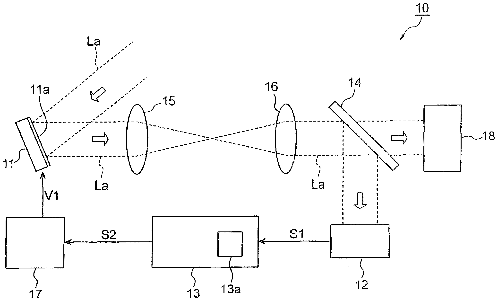
1 ist ein Diagramm, das schematisch einen Aufbau eines adaptiven Optiksystems gemäß einer Ausführungsform zeigt.1 is a diagram schematically showing a structure of an adaptive optics system according to an embodiment. -
2 ist eine Querschnittsansicht, die schematisch einen Aufbau eines Wellenfrontsensors einer Ausführungsform zeigt und einen Querschnitt entlang einer optischen Achse eines optischen Bildes darstellt.2 is a cross-sectional view schematically showing a structure of a wavefront sensor of an embodiment and illustrating a cross section along an optical axis of an optical image. -
3 ist eine Ansicht eines Linsen-Arrays, das in dem Wellenfrontsensor vorgesehen ist, wobei dieser in Richtung der optischen Achse eines optischen Bildes betrachtet wird.3 is a view of a lens array provided in the wavefront sensor, viewed in the direction of the optical axis of an optical image. -
4 ist eine Ansicht eines Bildsensors, der in dem Wellenfrontsensor bereitgestellt ist, der in Richtung der optischen Achse des optischen Bildes betrachtet wird.4 is a view of an image sensor provided in the wavefront sensor viewed in the optical axis direction of the optical image. -
5 ist eine Querschnittsansicht, die schematisch einen räumlichen Lichtmodulator des LCOS-Typs als ein Beispiel eines räumlichen Lichtmodulators einer Ausführungsform zeigt, wobei ein Querschnitt entlang der optischen Achse des optischen Bildes gezeigt ist.5 is a cross-sectional view schematically showing an LCOS type spatial light modulator as an example of a spatial light modulator of an embodiment, showing a cross section along the optical axis of the optical image. -
6 ist eine Frontansicht einer Modulationsoberfläche des räumlichen Lichtmodulators.6 is a front view of a modulation surface of the spatial light modulator. -
7 ist eine Konzeptansicht, die das Prinzip eines Justierverfahrens in einer Ausführungsform zeigt.7 is a conceptual view showing the principle of an adjustment method in an embodiment. -
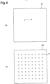
8 ist ein Diagramm, das konzeptionell ein spezielles Phasenmuster darstellt, das auf der Modulationsoberfläche angezeigt wird.8th is a diagram that conceptually represents a special phase pattern displayed on the modulation surface. -
9 ist ein Diagramm, das konzeptionell Daten einer Lichtintensitätsverteilung (Shack-Hartmann-Gram) darstellt, die von dem Bildsensor des Wellenfrontsensors erfasst werden.9 is a diagram that conceptually represents light intensity distribution (Shack-Hartmann-Gram) data acquired by the image sensor of the wavefront sensor. -
10 ist eine vergrößerte Ansicht der Umgebung des Wellenfrontsensors aus7 .10 is an enlarged view of the surroundings of the wavefront sensor from7 . -
11 ist eine Draufsicht, die eine vereinfachte Positionsrelation zwischen einem Wellenfrontteil und einer Linse zeigt, wenn die Betrachtung in Richtung der optischen Achse erfolgt.11 is a plan view showing a simplified positional relationship between a wavefront part and a lens when viewed in the direction of the optical axis. -
12 ist eine Ansicht, die eine zufällige Verteilung, in der eine Verteilung von Größen von Phasen unregelmäßig ist, als Beispiel eines räumlich nicht-linearen Phasenmusters darstellt.12 is a view that represents a random distribution in which a distribution of sizes of phases is irregular as an example of a spatially nonlinear phase pattern. -
13 ist eine Ansicht, die eine Defokussier-Verteilung darstellt, die einen Durchmesser eines konvergierenden Flecks als ein Beispiel des räumlich nicht-linearen Phasenmusters vergrößert.13 is a view illustrating a defocus distribution that increases a diameter of a converging spot as an example of the spatially nonlinear phase pattern. -
14 ist ein Diagramm, das eine Verteilung, die eine große sphärische Abberation in einem optischen Bild hervorruft, als ein Beispiel des räumlich nicht-linearen Phasenmusters zeigt.14 is a diagram showing a distribution that causes a large spherical aberration in an optical image as an example of the spatially nonlinear phase pattern. -
15 ist ein Diagramm, das eine Verteilung, die eine große Abberation hoher Ordnung in dem optischen Bild hervorruft, als ein Beispiel des räumlich nicht-linearen Phasenmusters zeigt.15 is a diagram showing a distribution that causes a large high-order aberration in the optical image as an example of the spatially nonlinear phase pattern. -
16 zeigt ein Beispiel eines Phasenmusters, in welchem eine gemeinsame Phasenverteilung (beispielsweise eine Defokussier-Verteilung) für alle zwei oder mehr Gebiete angeordnet ist.16 shows an example of a phase pattern in which a common phase distribution (e.g., a defocus distribution) is arranged for every two or more regions. -
17 zeigt ein Beispiel eines Phasenmusters, in welchem unterschiedliche Phasenverteilungen (beispielsweise Phasenverteilung mit einer Abberation hoher Ordnung) für jeweils alle zwei oder mehr Gebiete angeordnet sind.17 shows an example of a phase pattern in which different phase distributions (e.g. phase distribution with a high order aberration) are arranged for every two or more regions. -
18 ist ein Diagramm, das eine Phasenverteilung, in welchen Phasenwerte im Wesentlichen gleichmäßig über die gesamte Oberfläche der Modulationsoberfläche verteilt sind, als ein Beispiel eines Phasenmusters zeigt, das zumindest in einer Richtung Linearität besitzt.18 is a diagram showing a phase distribution in which phase values are substantially uniformly distributed over the entire surface of the modulation surface as an example of a phase pattern having linearity in at least one direction. -
19 ist eine Blockansicht, die ein Beispiel eines internen Aufbaus einer Steuereinheit zeigt.19 is a block diagram showing an example of an internal structure of a control unit. -
20 ist ein Flussdiagramm, das eine Funktionsweise und ein Justierverfahren für die Zuordnungsrelation des adaptiven Optiksystems darstellt.20 is a flowchart showing an operation and adjustment procedure for the mapping relation of the adaptive optics system. -
21 ist ein Diagramm, das ein rechteckiges Gebiet gegenüberliegend zu einer gewissen Linse auf einem Bildsensor und rechteckige Gebiete gegenüberliegend zu vier benachbarten Linsen um die Linse herum zeigt.21 is a diagram showing a rectangular area opposite a certain lens on an image sensor and rectangular areas opposite four adjacent lenses around the lens. -
22 ist ein vergrößertes Diagramm des Gebiets, das in21 gezeigt ist.22 is an enlarged diagram of the area covered in21 is shown. -
23 ist ein Flussdiagramm, das ein Verfahren zur Berechnung einer Eigenschaftsquantität eines konvergierenden Flecks zeigt.23 is a flowchart showing a method for calculating a property quantity of a converging spot. -
24 (a) ist ein Diagramm, das ein spezielles Phasenmusters zur Kalibrierung als ein Beispiel zeigt,24 (b) ist ein Diagramm, das Daten der Lichtintensitätsverteilung als ein Beispiel zeigt, wenn eine Positionsverschiebung in einer Linse auftritt, die einem ersten Gebiet entspricht, und24 (c) ist ein Diagramm, das Daten einer Lichtintensitätsverteilung als ein Beispiel nach Kalibrierung mit einer Linse, die dem ersten Gebiet entspricht, zeigt.24 (a) is a diagram showing a special phase pattern for calibration as an example,24 (b) is a diagram showing data of light intensity distribution as an example when a position shift occurs in a lens corresponding to a first region, and24 (c) is a graph showing data of a light intensity distribution as an example after calibration with a lens corresponding to the first region. -
25 ist ein Diagramm, das den Vorteil einer Erhöhung an Genauigkeit bei der Justierung (Kalibrierung) des adaptiven Optiksystems zeigt.25 is a diagram showing the benefit of increasing accuracy in the adjustment (calibration) of the adaptive optics system. -
26 ist ein Flussdiagramm, das ein Justierverfahren (eine Funktionsweise einer Steuereinheit) für das adaptive Optiksystem gemäß einem modifizierten Beispiel zeigt.26 is a flowchart showing an adjustment method (an operation of a control unit) for the adaptive optics system according to a modified example. -
27 ist ein Diagramm, das Beispiele diverse Größen des ersten Gebiets zeigt.27 is a diagram showing examples of various sizes of the first area. -
28 ist ein Diagramm, das eine Phasenverteilung darstellt, in welcher Phasenwerte in einer ersten Richtung (beispielsweise eine Zeilenrichtung) geneigt sind und in der Phasenwerte in einer zweiten Richtung (beispielsweise eine Spaltenrichtung), die die erste Richtung schneidet (senkrecht dazu ist) im Wesentlichen gleichmäßig angeordnet sind.28 is a diagram illustrating a phase distribution in which phase values in a first direction (e.g., a row direction) are tilted and in which phase values in a second direction (e.g., a column direction) that intersects (is perpendicular to) the first direction are substantially evenly arranged. -
29 ist ein Diagramm, das eine Phasenverteilung zeigt, in der Phasenwerte sowohl in der ersten Richtung (beispielsweise die Zeilenrichtung) als auch in der zweiten Richtung (beispielsweise die Spaltenrichtung) geneigt bzw. sich linear ändernd sind.29 is a diagram showing a phase distribution in which phase values are inclined or linearly changing in both the first direction (e.g., the row direction) and the second direction (e.g., the column direction). -
30 ist ein Diagramm, das eine Phasenverteilung zeigt mit der Wirkung einer Zylinderlinse in der ersten Richtung und in der Phasenwerte im Wesentlichen gleichförmig in der zweiten Richtung sind, wobei dies als ein Beispiel eines Phasenmusters mit Linearität in mindestens einer Richtung dient.30 is a diagram showing a phase distribution having the effect of a cylindrical lens in the first direction and in which phase values are substantially uniform in the second direction, serving as an example of a phase pattern having linearity in at least one direction. -
31 ist ein Diagramm, das eine Phasenverteilung zeigt, die ein Beugungsgitter in der ersten Richtung bildet, und in dem Phasenwerte in der zweiten Richtung im Wesentlichen gleichförmig sind, wobei dies als ein Beispiel eines Phasenmusters dient, das in mindestens einer Richtung Linearität besitzt.31 is a diagram showing a phase distribution which forms a diffraction grating in the first direction and in which phase values in the second direction are substantially uniform, serving as an example of a phase pattern having linearity in at least one direction. -
32 ist ein Diagramm, das ein Beispiel eines zusammengesetzten Musters zeigt, das durch Überlagerung erhalten wird.32 is a diagram showing an example of a composite pattern obtained by superposition. -
33 ist ein Diagramm, das ein modifiziertes Beispiel eines Linsen-Arrays zeigt.33 is a diagram showing a modified example of a lens array. -
34 ist ein Diagramm, das jedes Gebiet, das in21 dargestellt ist, und ein modifiziertes Beispiel eines Berechnungsgebiets für die Größe bzw. Quantität einer Eigenschaft zeigt.34 is a diagram that shows each area that is21 and shows a modified example of a calculation region for the size or quantity of a property. -
35 ist eine vergrößerte Ansicht der Umgebung des Wellenfrontsensors aus7 .35 is an enlarged view of the surroundings of the wavefront sensor from7 . -
36 ist ein Diagramm, das ein Beispiel einer Anordnung eines ersten Gebiets zeigt.36 is a diagram showing an example of an arrangement of a first region. -
37 ist ein Diagramm, das ein Beispiel des Falles zeigt, in welchem eine Größe des ersten Gebiets variabel ist.37 is a diagram showing an example of the case where a size of the first region is variable.
Beschreibung von AusführungsformenDescription of embodiments
Im Folgenden sind mit Bezug zu den begleitenden Zeichnungen Ausführungsformen eines Justierverfahrens für ein adaptives Optiksystem, ein adaptives Optiksystem, ein Programm für ein adaptives Optiksystem und ein Speichermedium zur Speicherung eines Programms für ein adaptives Optiksystem gemäß einem Aspekt der vorliegenden Erfindung beschrieben. Ferner werden die gleichen Elemente mit gleichen Bezugszeichen in der Beschreibung der Zeichnungen bezeichnet und eine wiederholte Beschreibung ist daher weggelassen. Ferner wird in der folgenden Beschreibung angenommen, dass eine „Phasenverteilung“ zweidimensionale verteilte Phasenwerte bezeichnet, ein „Phasenmuster“ ein Muster bezeichnet, das durch Kodierung der Phasenverteilung (zweidimensionale Phasenwerte) auf der Grundlage eines gewissen Standards erhalten wird, und ein „Phasenprofil“ eine Verteilung von Phasenwerten in einer gewissen Richtung (Linie) in der Phasenverteilung bezeichnet.Hereinafter, embodiments of an adjustment method for an adaptive optics system, an adaptive optics system, a program for an adaptive optics system, and a storage medium for storing a program for an adaptive optics system according to an aspect of the present invention will be described with reference to the accompanying drawings. Furthermore, the same elements are denoted by the same reference numerals in the description of the drawings, and repeated description is therefore omitted. Furthermore, in the following description, it is assumed that a "phase distribution" refers to two-dimensionally distributed phase values, a "phase pattern" refers to a pattern obtained by encoding the phase distribution (two-dimensional phase values) based on a certain standard, and a "phase profile" refers to a distribution of phase values in a certain direction (line) in the phase distribution.
(Ausführungsformen)(Embodiments)
Der räumliche Lichtmodulator 11 empfängt ein optisches Bild La mittels einer Modulationsoberfläche 11a, die ein Phasenmuster anzeigt und eine Wellenfrontform des optischen Bildes La moduliert, um die modulierte Form der Wellenfront auszugeben. Das optische Bild La, das auf den räumlichen Lichtmodulator 11 einfällt, ist beispielsweise Licht, das von einer Laser-Lichtquelle oder einer super-leuchtstarken Diode (SLD) ausgesandt wird, oder ist reflektiertes Licht, gestreutes Licht, Fluoreszenzlicht oder dergleichen, das von einem Beobachtungsobjekt, das mit Licht bestrahlt wird, erzeugt wird. Der Wellenfrontsensor 12 versorgt die Steuereinheit 13 mit Daten S1 einschließlich von Information über die Form der Wellenfront des optischen Bildes La, das den räumlichen Lichtmodulator 11 erreicht (typischerweise wird eine Verzerrung einer Wellenfront angezeigt, d.h., eine Verschiebung einer Wellenfront in Bezug auf eine Referenzfront, aufgrund einer Abberation bzw. eines Abbildungsfehlers eines optischen Systems). Die Steuereinheit 13 erzeugt ein Steuersignal S2 zur Anzeige eines Phasenmusters, das für den räumlichen Lichtmodulator 11 geeignet ist, auf der Grundlage der Daten S1, die aus dem Wellenfrontsensor 12 erhalten werden. In einem Beispiel umfasst die Steuereinheit 13 eine Eingabeeinheit, die ausgebildet ist, die Daten S1 aus dem Wellenfrontsensor 12 einzuspeisen, eine Abberationsberechnungseinheit, die ausgebildet ist, eine Abberation bzw. einen Abbildungsfehler aus den Daten S1 zu berechnen, eine Phasenmuster-Berechnungseinheit, die ausgebildet ist, ein in dem räumlichen Lichtmodulator 11 anzuzeigendes Phasenmuster zu berechnen, und eine Signalerzeugungseinheit, die ausgebildet ist, das Steuersignal S2 entsprechend dem berechneten Phasenmusters zu erzeugen. Die Steuerschaltungseinheit 17 empfängt das Steuersignal S2 aus der Steuereinheit 13 und legt eine Spannung V1 auf der Grundlage des Steuersignals S2 an mehrere Elektroden des räumlichen Lichtmodulators 11 an.The spatial light modulator 11 receives an optical image La by means of a
Der Strahlteiler 14 ist zwischen dem Wellenfrontsensor 12 und dem räumlichen Lichtmodulator 12 angeordnet und teilt das optische Bild La auf. Der Strahlteiler 14 kann ein Strahlteiler des Typs sein, der von der Polarisationsrichtung unabhängig ist, kann ein Polarisationsrichtung abhängiger Typ oder ein wellenlängenabhängiger Typ (dichroischer Spiegel) sein. Ein optisches Bild La, das beispielsweise von dem Strahlteiler 14 abgezweigt wird, wird zu einem optischen Erfassungselement 18, etwa ein CCD, eine Fotovervielfacher-Röhre oder eine Avalanche-Fotodiode gesendet. Das optische Erfassungselement 18 ist beispielsweise in einem Raster-Laser-Ophtalmoskop (SLO), einer optischen Kohärenz-Tomographie-(OCT) Kamera, einer Augengrund-Kamera, einem Mikroskop, einem Teleskop oder dergleichen enthalten. Ferner fällt das andere optische Bild La, das von dem Strahlteiler 14 abgezweigt wird, auf den Wellenfrontsensor 12.The
Die Übertragungslinsen 15 und 16 sind nebeneinander in Richtung der optischen Achse zwischen dem Wellenfrontsensor 12 und dem räumlichen Lichtmodulator 11 angeordnet. Der Wellenfrontsensor 12 und der räumlichen Lichtmodulator 11 sind in einer zueinander optisch konjugierten Relation durch die Übertragungslinsen 15 und 16 gehalten. Des Weiteren können eine optische Abbildungslinse bzw. ein Abbildungsobjektiv und/oder ein Polarisationsspiegel, usw. zwischen dem Wellenfrontsensor 12 und dem räumlichen Lichtmodulator 11 angeordnet sein.The
Obwohl der Wellenfrontsensor 12 ein Interferenz-Typ oder ein Nicht-Interferenz-Typ sein kann, wird der Shack-Hartmann-Wellenfrontsensor des Nicht-Interferenz-Typs mit dem Linsen-Array 120 und dem Bildsensor 122 als der Wellenfrontsensor 12 in dieser Ausführungsform verwendet. Wenn der Wellenfrontsensor des Nicht-Interferenz-Typs verwendet wird, ergibt sich ein Vorteil dahingehend, dass die Unempfindlichkeit bei Erschütterung ausgezeichnet ist und ein Aufbau des Wellenfrontsensors und ein Vorgang zur Berechnung von Messdaten können einfacher sein im Vergleich dazu, dass der Wellenfrontsensor als ein Interferenz-Typ verwendet wird.Although the
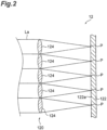
Wie in
Des Weiteren hat der in
In der Steuereinheit 13, die nachfolgend beschrieben ist, wird eine Form der Wellenfront (eine Verteilung von Phasengradienten) des optischen Bildes La auf der Grundlage einer Lichtintensitätsverteilung gemessen, die von dem Bildsensor 122 erfasst wird. D.h., eine Größe an Verschiebung zwischen der Position des konvergierenden Flecks P durch die Linse 124 und der Referenzposition ist proportional zu einer Steigung einer lokalen Wellenfront des optischen Bildes La, das auf die Linse 124 einfällt. Daher ist es möglich, die Größe der Positionsverschiebung des konvergierenden Flecks P aus der Referenzposition für die Linse 124 zu berechnen und eine Form der Wellenfront des optischen Bildes La auf der Grundlage der Positionsverschiebung des konvergierenden Flecks P zu messen.In the
Es ist möglich, eine Position, an der eine optische Achse jeder der mehreren Linsen 124 die Licht empfangende Oberfläche 122a des Bildsensors 122 schneidet, als die Referenzposition anzugeben, die zur Berechnung der Größe der Verschiebung der konvergierenden Bildposition zu verwenden ist. Diese Position wird einfach durch eine Schwerpunktsberechnung erhalten, indem ein konvergierendes Bild, das erhalten wird, indem parallele ebene Wellen hervorgerufen werden, die senkrecht auf jede Linse 124 einfallen, verwendet wird.It is possible to specify a position at which an optical axis of each of the plurality of
Der räumliche Lichtmodulator 11 ist ein Element, das das optische Bild La aus einer Lichtquelle oder einem Beobachtungsobjekt empfängt und eine Wellenfront des optischen Bildes La moduliert, um die modulierte Wellenfront auszugeben. Insbesondere hat der räumliche Lichtmodulator 11 mehrere Pixel (Steuerpunkte), die in Form eines zweidimensionalen Gitters angeordnet sind, und er ändert einen Modulationsbetrag (beispielsweise den Betrag einer Phasenmodulation) für jedes Pixel entsprechend dem Steuersignal S2, das von der Steuereinheit 13 bereitgestellt wird. Der räumliche Lichtmodulator 11 umfasst beispielsweise einen räumlichen Lichtmodulator mit Flüssigkristall auf Silizium (LCOS-SLM), einen programmierbaren Phasenmodulator (PPM), eine Flüssigkristallanzeige (LCD), mikro-elektro-mechanische Systeme (MEMS), oder einen räumlichen Lichtmodulator des Typs mit elektrischer Adressierung, der durch Kopplung eines LCD-Elements und eines räumlichen Lichtmodulators mit Flüssigkristall des Typs mit optische Adressierung gebildet ist. Obwohl ferner der räumliche Lichtmodulator 11 als Reflexions-Typ in
Das transparente Substrat 111 ist aus einem Material hergestellt, das das optische Bild La durchlässt, und ist entlang einer Hauptoberfläche des Siliziumsubstrats 112 angeordnet. Die mehreren Pixel-Elektroden 113 sind in Form eines zweidimensionalen Gitters auf der Hauptoberfläche des Siliziumsubstrats 112 angeordnet und bilden die Pixel des räumlichen Lichtmodulators 11. Die transparente Elektrode 115 ist auf der Oberfläche des transparenten Substrats 111 gegenüberliegend zu den mehreren Pixel-Elektroden 113 angeordnet. Die Flüssigkristalleinheit 114 ist zwischen den mehreren Pixel-Elektroden 113 und der transparenten Elektrode 115 angeordnet. Die orientierte Schicht 116a ist zwischen der Flüssigkristalleinheit 114 und der transparenten Elektrode 115 angeordnet und die orientierte Schicht 116b ist zwischen der Flüssigkristalleinheit 114 und den mehreren Pixel-Elektroden 112 angeordnet. Der dielektrische Spiegel 117 ist zwischen der orientierten Schicht 116b und den mehreren Pixel-Elektroden 113 angeordnet. Der dielektrische Spiegel 117 reflektiert das optische Bild La, das ausgehend von dem transparenten Substrat 111 einfällt, und durch die Flüssigkristalleinheit 114 durchgelassen wird und bewirkt, dass das optische Bild La von dem transparenten Substrat 111 erneut ausgesendet wird.The transparent substrate 111 is made of a material that transmits the optical image La and is arranged along a main surface of the silicon substrate 112. The plurality of pixel electrodes 113 are arranged in the form of a two-dimensional grid on the main surface of the silicon substrate 112 and form the pixels of the spatial light modulator 11. The transparent electrode 115 is arranged on the surface of the transparent substrate 111 opposite to the plurality of pixel electrodes 113. The liquid crystal unit 114 is arranged between the plurality of pixel electrodes 113 and the transparent electrode 115. The oriented layer 116a is arranged between the liquid crystal unit 114 and the transparent electrode 115, and the oriented layer 116b is arranged between the liquid crystal unit 114 and the plurality of pixel electrodes 112. The dielectric mirror 117 is arranged between the oriented layer 116b and the plurality of pixel electrodes 113. The dielectric mirror 117 reflects the optical image La incident from the transparent substrate 111 and transmitted through the liquid crystal unit 114 and causes the optical image La to be re-emitted from the transparent substrate 111.
Der räumliche Lichtmodulator 11 umfasst ferner eine Pixel-Elektrodenschaltung (Treiberschaltung für aktive Matrix) 119, die ausgebildet ist, eine zwischen den mehreren Pixel-Elektroden 113 und der transparenten Elektrode 115 anzulegende Spannung zu steuern. Wenn die Spannung von der Pixel-Elektrodenschaltung 119 an eine beliebige Pixel-Elektrode 113 angelegt wird, ändert sich ein Brechungsindex der Flüssigkristalleinheit 114 an der Pixel-Elektrode 113 entsprechend einer Größe eines elektrischen Feldes, das zwischen der Pixel-Elektrode 113 und der transparenten Elektrode 115 erzeugt wird. Folglich ändert sich eine optische Weglänge des optischen Bildes La, das durch einen entsprechenden Teil der Flüssigkristalleinheit 114 durchgelassen wird, und daher letztlich auch eine Phase des optischen Bildes La. Durch Anlegen von Spannungen mit unterschiedlichen Größen an die mehreren Pixel-Elektroden 113 ist es möglich, eine räumliche Verteilung eines Betrages der Phasenjustierung elektrisch zu schreiben und bei Bedarf diverse Formen für Wellenfronten umzusetzen.The spatial light modulator 11 further includes a pixel electrode circuit (active matrix driving circuit) 119 configured to control a voltage to be applied between the plurality of pixel electrodes 113 and the transparent electrode 115. When the voltage from the pixel electrode circuit 119 is applied to any pixel electrode 113, a refractive index of the liquid crystal unit 114 at the pixel electrode 113 changes according to a magnitude of an electric field generated between the pixel electrode 113 and the transparent electrode 115. Consequently, an optical path length of the optical image La transmitted through a corresponding part of the liquid crystal unit 114 changes, and hence ultimately a phase of the optical image La also changes. By applying voltages of different magnitudes to the plurality of pixel electrodes 113, it is possible to obtain a spatial distribution to electrically write an amount of phase adjustment and, if necessary, to implement various shapes for wavefronts.
Die Beschreibung geht zurück zu
Dabei wird ein Koordinatensystem in der Modulationsoberfläche 11a des räumlichen Lichtmodulators 11 und der Erfassungsoberfläche des Wellenfrontsensors 12 wie folgt festgelegt. D.h., zwei Richtungen parallel zu der Modulationsoberfläche 11a des räumlichen Lichtmodulators 11 und senkrecht zueinander werden als eine x-Achsenrichtung und eine y-Achsenrichtung in der Modulationsoberfläche 11a gekennzeichnet, und zwei Richtungen parallel zu der Erfassungsoberfläche des Wellenfrontsensors 12 und senkrecht zueinander werden als eine x-Achsenrichtung und eine y-Achsenrichtung in der Erfassungsoberfläche ausgewählt. Jedoch sind die x-Achse in der Modulationsoberfläche 11a des räumlichen Lichtmodulators 11 und die x-Achse in der Erfassungsoberfläche des Wellenfrontsensors 12 so ausgerichtet, dass sie entgegengesetzt zueinander ausgerichtet sind, und die y-Achse in der Modulationsoberfläche 11a des räumlichen Lichtmodulators 11 und die y-Achse in der Erfassungsoberfläche des Wellenfrontsensors 12 sind so ausgerichtet, dass sie entgegengesetzt zueinander sind. Auch Koordinaten, an denen der Mittelpunkt der Modulationsoberfläche 11a des räumlichen Lichtmodulators 11 als der Ursprung festgelegt ist, werden als (Xs, Ys) gesetzt und Koordinaten, an denen der Mittelpunkt der Erfassungsoberfläche des Wellenfrontsensors 12 als der Ursprung zugeordnet ist, werden als (Xc, Yc) festgelegt.Here, a coordinate system in the
Dabei wird die Phase der Wellenfront an einer Position (Xs, Ys) auf der Modulationsoberfläche 11a des räumlichen Lichtmodulators 11 Eins-zu-Eins auf die Phase der Wellenfront an einer Position (Xc, Yc) auf der Erfassungsoberfläche des Wellenfrontsensors 12 abgebildet und eine Beziehung zwischen diesen wird durch die folgenden Formeln (1) ausgedrückt, wenn es keine Rotationsverschiebung zwischen der Modulationsoberfläche 11a und der Erfassungsoberfläche gibt.
[Mathe 1]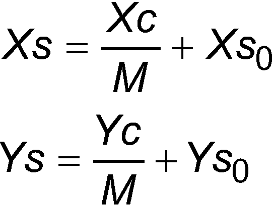
[Math 1]
Dabei bezeichnet M Vergrößerungen der Linsen 15 und 16. Des Weiteren bezeichnet (Xs0, Ys0) Koordinaten auf der Modulationsoberfläche 11a des räumlichen Lichtmodulators 11, die auf einen Koordinatenursprung auf der Erfassungsoberfläche des Wellenfrontsensors 12 projiziert sind, und bezeichnet einen Betrag an Positionsverschiebung zwischen der Modulationsoberfläche 11a und der Erfassungsoberfläche. Ferner ist die Vergrößerung M, die in den Formeln (1) enthalten ist, in vielen Fällen bekannt.Here, M denotes magnifications of the
Die Justierung (Kalibrierung) einer Zuordnungsrelation zwischen der Modulationsoberfläche 11a und dem Wellenfrontsensor 12 des adaptiven optischen Systems 10 in dieser Ausführungsform ist eine Untersuchung eines Wertes des zuvor beschriebenen (Xs0, Ys0) und der Vorgang, den Wert auf nahe null zu bringen. Anders ausgedrückt, dies ist die Justierung einer relativen Relation zwischen einer Befestigensposition des Wellenfrontsensors 12 und einer Befestigungsposition des räumlichen Lichtmodulators 11. Alternativ wird der Wert des zuvor beschriebenen (Xs0, Ys0) bei der Justierung (Kalibrierung) einer Zuordnungsrelation zwischen der Modulationsoberfläche 11a und dem Wellenfrontsensor 12 in Betracht gezogen, wenn ein den räumlichen Lichtmodulator 11 zugewiesenes Phasenmuster mit einer Wellenfrontform einhergeht, die aus dem Wellenfrontsensor 12 erhalten wird. Anders ausgedrückt, dies ist die Justierung einer relativen Positionsrelation zwischen den Positionskoordinaten, die auf der Modulationsoberfläche 11a angenommen werden, wenn das Phasenmuster zum Kompensieren einer Wellenfrontverzerrung angezeigt wird, und dem Wellenfrontsensor 12.The adjustment (calibration) of a correspondence relation between the
In dem Justierverfahren für das adaptiven Optiksystem gemäß dieser Ausführungsform wird ein spezielles Phasenmuster für die Justierung in dem räumlichen Lichtmodulator 11 angezeigt und eine Eigenschaft, die aufgrund des Phasenmusters in dem Wellenfrontsensor 12 auftritt, wird erfasst, so dass ein Betrag an Positionsverschiebung zwischen der Form der Wellenfront, die in dem Wellenfrontsensor 12 gemessen wird, und dem Phasenmuster, das in dem räumlichen Lichtmodulator 11 angezeigt wird, erhalten wird und die Justierung (Kalibrierung) der Zuordnungsrelation zwischen der Modulationsoberfläche 11a und dem Wellenfrontsensor 12 wird auf Grundlage des Betrags an Positionsverschiebung ausgeführt.In the adjustment method for the adaptive optics system according to this embodiment, a specific phase pattern for adjustment is displayed in the spatial light modulator 11, and a characteristic occurring due to the phase pattern in the
Im Weiteren ist ein Verfahren der Justierung (Kalibrierung) der Zuordnungsrelation zwischen der Modulationsoberfläche 11a und dem Wellenfrontsensor 12 detailliert beschrieben. Das Justierverfahren ist auch als ein Programm in einem Speichergebiet 13a der Steuereinheit 13 gespeichert, die in
Dabei ist
Gleichzeitig ist ein räumlich nicht-lineares zweites Phasenmuster (beispielsweise eine zufällige Verteilung, in der eine Verteilung von Größen von Phasen unregelmäßig ist, eine Defokussier-Verteilung, die einen Durchmesser eines konvergierenden Flecks vergrößert, oder dergleichen) in einem Gebiet B2 (das im Weiteren als ein zweites Gebiet bezeichnet ist), das das erste Gebiet B1 auf der Modulationsoberfläche 11a umgibt, angezeigt. Damit wird eine Wellenfront eines Teils, der dem zweiten Gebiet B2 in der ausgesandten Wellenfront W2 entspricht, gestört (Teil A1 der
Andererseits fällt die Wellenfront auf die Linse 124, ohne dass sie in mindestens einer Richtung gestört wird, entsprechend einem ersten Phasenmuster mit Linearität in der zumindest einen Richtung in Teilen (Teile A3 und A4 der
Wenn das Phasenmuster mit der Linearität in allen Gebieten angezeigt wird, wie in
Das Beispiel der Lichtintensitätsverteilung, die in
Wenn andererseits eine Positionsverschiebung zwischen dem Phasenmuster des Wellenfrontsensors 12 und dem räumlichen Lichtmodulator 11 auftritt, wie in
Daher ist es möglich, einen Betrag an Positionsverschiebung zwischen dem Teil A4 der Wellenfront und der speziellen Linse 124 zu kennen (d.h., einen Betrag an Positionsverschiebung bzw. Abweichung zwischen dem auf dem räumlichen Lichtmodulator 11 angezeigten Phasenmuster und der Form der Wellenfront, die in der Wellenfrontoberfläche 12 gemessen wird), indem die Verteilung des konvergierenden Flecks P untersucht wird, der in den Daten der Lichtintensitätsverteilung D1 enthalten ist.Therefore, it is possible to know an amount of positional shift between the part A4 of the wavefront and the special lens 124 (i.e., an amount of positional shift between the phase pattern displayed on the spatial light modulator 11 and the shape of the wavefront measured in the wavefront surface 12) by examining the distribution of the converging spot P included in the data of the light intensity distribution D1.
Hier ist ein Beispiel eines „räumlich nicht-linearen zweiten Phasenmusters“, das in dem zweiten Gebiet B2 der
Ferner kann das nicht-lineare Phasenmuster, das in dem zweiten Gebiet B2 angezeigt ist, eine gemeinsame Phasenverteilung für alle zwei oder mehr Gebiete, die durch Teilung des zweiten Gebiets B2 gebildet sind, enthalten und kann unterschiedliche Phasenverteilungen für jeweils zwei oder mehr Gebiete enthalten, die durch Unterteilen des zweiten Gebiets B2 gebildet sind.
Ein „erstes Phasenmuster mit Linearität in mindestens einer Richtung“, das in dem ersten Gebiet B1 der
Die Mustererzeugungseinheit 13b erzeugt ein spezielles Phasenmuster für die Justierung (Kalibrierung) einer Zuordnungsrelation zwischen der Modulationsoberfläche 11a und dem Wellenfrontsensor 12, das heißt, ein Phasenmuster, das das erste Gebiet B1 und das zweite Gebiet B2 enthält. Des Weiteren erzeugt die Mustererzeugungseinheit 13b ein räumlich nicht-lineares Phasenmuster in allen Gebieten separat zu dem zuvor beschriebenen Phasenmuster. Diese Phasenmuster werden auch an die Steuerschaltungseinheit 17 als das Steuersignal S2 von der Mustererzeugungseinheit 13b gesendet.The
Dabei ist ein spezielles Phasenmuster PA für die Kalibrierung beispielsweise durch die folgende Formel (2) ausgedrückt.
[Mathe 2![]()
[Math 2![]()
Dabei bezeichnet a eine gewisse Konstante und ist ein Beispiel eines ersten Phasenmusters mit Linearität in mindestens einer Richtung. rand()bezeichnet eine Zufallsfunktion und ist ein Beispiel eines räumlich nicht-linearen zweiten Phasenmusters, (n, m) bezeichnen Koordinaten in Einheiten von Pixel auf der Modulationsoberfläche 11a. ROI ist als Bezugszeichen definiert, das das erste Gebiet B1 kennzeichnet. Des Weiteren wird ein Phasenmuster PB, das nicht räumlich linear in allen Gebieten ist, durch die folgende Formel (3) ausgedrückt.
[Mathe 3]![]()
[Math 3]![]()
Wie zuvor beschrieben ist, hat das erste Gebiet B1 in dieser Ausführungsform eine Größe, die einer einzelnen Linse 124 entspricht. Wenn die mehreren Linsen 124 in Form eines zweidimensionalen Gitters angeordnet sind, wie in
[Mathe 4]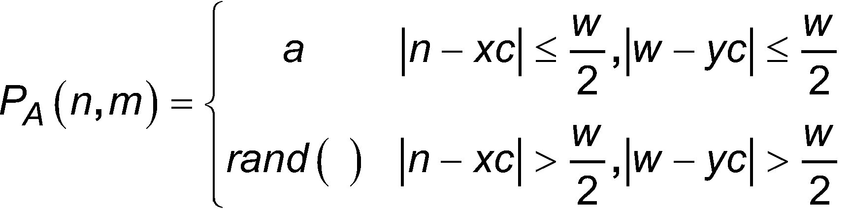
[Math 4]
Dabei sind (xc, yc) Mittelpunktskoordinaten des ersten Gebiets B1 und w ist die Anzahl an Pixel einer Seite des ersten Gebiets B1. Wenn ferner angenommen wird, dass ein Array-Abstand der Pixel 11b in der Modulationsoberfläche 11a durch sImPITCH angegeben ist, ein Array-Abstand der Linsen in dem Linsen-Array 120 durch mlaPITCH angegeben ist, und eine Abbildungsvergrößerung eines optischen Systems zwischen der Modulationsoberfläche 11a und der Linsenoberfläche des Linsen-Array 120 als M bezeichnet ist, wird die Anzahl an Pixel w einer Seite des ersten Gebiets B1 durch die folgende Formel (5) ausgedrückt.
[Mathe 5]![]()
[Math 5]![]()
Anders ausgedrückt, eine Breite (=w×slmPITCH) des ersten Gebiets B1 in einer Array-Richtung der mehreren Linsen 124 ist (1/M) mal dem Array-Abstand mlaPITCH der mehreren Linsen 124.In other words, a width (=w×slmPITCH) of the first region B1 in an array direction of the plurality of
Wenn jedes der zuvor beschriebenen Phasenmusters PA und PB auf der Modulationsoberfläche 11a angezeigt wird, erhält die Berechnungsverarbeitungseinheit 13c die Daten der Lichtintensitätsverteilung S1, die von dem Wellenfrontsensor 12 ausgegeben werden. Die Berechnungsverarbeitungseinheit 13c berechnet eine Größe einer Eigenschaft bzw. eine Eigenschaftsquantität, die mit dem konvergierenden Fleck P in Beziehung steht, der in den Daten der Lichtintensitätsverteilung S1 enthalten ist, entsprechend einem Algorithmus, der nachfolgend beschrieben ist. Die Berechnungsverarbeitungseinheit 13c verschiebt eine Mittelposition (xc, yc) des ersten Gebiets B1 derart, dass die Eigenschaftsquantität einer Bedingung genügt (typischerweise so, dass die Eigenschaftsquantität minimiert wird, oder so dass die Eigenschaftsquantität kleiner als ein vorbestimmter Schwellwert ist).When each of the above-described phase patterns P A and P B is displayed on the
Eine Funktionsweise des adaptiven Optiksystems 10 einschließlich der Justierung (Kalibrierung) der Zuordnungsrelation zwischen der Modulationsoberfläche 11a und dem Wellenfrontsensor 12, die zuvor beschrieben sind, ist mit Bezug zu
In dem adaptiven Optiksystem 10 wird zunächst eine Initialisierung der Steuereinheit 13 ausgeführt (Schritt S11). In diesem Initialisierungsschritt S11 werden beispielsweise die Reservierung eines Speichergebiets, das für eine Berechnung erforderlich ist, anfängliche Einstellungen von Parametern, usw. ausgeführt. Des Weiteren kann in diesem Schritt S11 die Mitte des ersten Gebiets B1 in jedem Pixel in der Umgebung des Mittelpunkts der Modulationsoberfläche 11a als ein Initialisierungsprozess für ein spezielles Phasenmuster PA für die Kalibrierung zugewiesen werden. Des Weiteren kann die Anzahl an Iterationen der nachfolgenden Schritte S12 bis S19 festgelegt werden. Die Anzahl an Iterationen wird beispielsweise auf eine ganze Zahl festgelegt, die größer ist als ein Wert, der durch Quadrieren der Anzahl an Pixel einer Seite des ersten Gebiets B1 ermittelt wird.In the
Als nächstes erzeugt die Steuereinheit 13 das spezielle Phasenmuster PA für die Kalibrierung und zeigt das erzeugte Phasenmuster PA auf der Modulationsoberfläche 11a an (Schritt S12). In diesem Schritt S12 wird ein Phasenmuster (siehe beispielsweise
Nachfolgend erhält die Steuereinheit 13 Daten der Lichtintensitätsverteilung (im Weiteren werden diese Daten der Lichtintensitätsverteilung als DA bezeichnet) aus dem Bildsensor 122 in einem Zustand, in welchem das zuvor beschriebene Phasenmuster PA angezeigt wird (Schritt S13, erster Schritt zur Gewinnung einer Lichtintensitätsverteilung).Subsequently, the
Nachfolgend erzeugt die Steuereinheit 13 ein Phasenmuster PB, das räumlich nicht linear in allen Gebieten ist und zeigt das erzeugte Phasenmuster PB auf der Modulationsoberfläche 11a an (Schritt S14). In diesem Schritt S14 wird das räumlich nicht-lineare Phasenmuster (siehe beispielsweise
Danach erhält die Steuereinheit 13 Daten der Lichtintensitätsverteilung (im Weiteren wird diese Lichtintensitätsverteilung als Da bezeichnet) durch den Bildsensor 122 in einem Zustand, in welchem das oben beschriebene Phasenmuster PB angezeigt wird (Schritt S15, zweiter Schritt zur Gewinnung der Lichtintensitätsverteilung).Thereafter, the
Nachfolgend ermittelt die Steuereinheit 13 einen numerischen Wert, der mit der Klarheit bzw. Deutlichkeit des konvergierenden Flecks P in Beziehung steht, der in den Daten der Lichtintensitätsverteilung DA enthalten ist, und einen numerischen Wert, der mit der Klarheit bzw. Deutlichkeit des konvergierenden Flecks P in Beziehung steht, der in den Daten der Lichtintensitätsverteilung DB enthalten ist (Schritt S16). Dabei wird der numerische Wert, der mit der Deutlichkeit des konvergierenden Flecks P in Beziehung steht, als eine „Eigenschaftsquantität“ bezeichnet. Im Weiteren ist ein Verfahren zur Ermittelung der Eigenschaftsquantität beschrieben.Subsequently, the
[Mathe 6]![]()
[Math 6]![]()
Des Weiteren werden Berechnungsgebiete für die Eigenschaftsquantität R0 bis R4 innerhalb der Gebiete L0 bis L4 festgelegt. Die Berechnungsgebiete für die Eigenschaftsquantität R0 bis R4 haben beispielsweise ähnliche Formen wie die Gebiete L1 bis L4 und die Mittelpositionen der Berechnungsgebiete für die Eigenschaftsquantität R0 bis R4 stimmen mit der Mittelposition der Gebiete L1 bis L4 über ein.Furthermore, calculation areas for the property quantity R0 to R4 are defined within the areas L0 to L4. The calculation areas for the property quantity R0 to R4 have, for example, similar shapes to the areas L1 to L4, and the center positions of the calculation areas for the property quantity R0 to R4 coincide with the center position of the areas L1 to L4.
[Mathe 7]
[Maths 7]
Da der Schwerpunkt des konvergierenden Flecks P und die Mittelpositionen des Gebiets L0 und des Berechnungsgebiets für die Eigenschaftsquantität R0 in vielen Fällen miteinander übereinstimmen, werden die Mittelpunktskoordinaten der Gebiete L0 und R0 durch (cx, cy) bezeichnet. Des Weiteren werden die Mittelpunktskoordinaten der Gebiete L1 und R1 durch (cx-d, cy) bezeichnet, die Mittelpunktskoordinaten der Gebiete L2 und R2 werden durch (cx+d, cy) bezeichnet, die Mittelpunktskoordinaten der Gebiete L3 und R3 werden durch (cx, cy-d) bezeichnet, und die Mittelpunktskoordinaten der Gebiete L4 und R4 werden durch (cx, cy+d) bezeichnet.Since the center of gravity of the converging spot P and the center positions of the region L0 and the calculation region for the property quantity R0 coincide with each other in many cases, the center coordinates of the regions L0 and R0 are denoted by (c x , c y ). Furthermore, the center coordinates of the regions L1 and R1 are denoted by (c x -d, c y ), the center coordinates of the regions L2 and R2 are denoted by (c x +d, c y ), the center coordinates of the regions L3 and R3 are denoted by (c x , c y -d), and the center coordinates of the regions L4 and R4 are denoted by (c x , c y +d).
Als nächstes werden in den Berechnungsgebieten für die Eigenschaftsquantität R1 bis R4 der vier Gebiete L1 bis L4, die benachbart zu dem Gebiet L0 liegen, das die Höchstwertposition des konvergierenden Flecks P enthält, die Eigenschaftsquantitäten VA1, VA2, VA3, und VA4, die durch die folgenden Formeln (8) ausgedrückt sind, berechnet (Schritt S22).
[Mathe 8]
[Math 8]
Anschließend werden in den Berechnungsgebieten für die Eigenschaftsquantität R1 bis R4 in den Daten der Lichtintensitätsverteilung DB Eigenschaftsquantitäten VB1, VB2, VB3, und VB4, die durch die folgenden Formeln (9) ausgedrückt sind, berechnet (Schritt S23).
[Mathe 9]
[Math 9]
Somit sind die Eigenschaftsquantitäten VA1 bis VA4 der konvergierenden Flecken P, die in den Daten der Lichtintensitätsverteilung DA und die Eigenschaftsquantitäten VB1 bis VB4 der konvergierenden Flecke P, die in den Daten der Lichtintensitätsverteilung DB enthalten sind, berechnet.Thus, the property quantities V A1 to V A4 of the converging spots P included in the data of the light intensity distribution D A and the property quantities V B1 to V B4 of the converging spots P included in the data of the light intensity distribution D B are calculated.
Die Beschreibung geht nun zurück zu ![]()
[Mathe 10]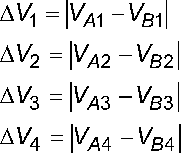
![]()
[Math 10]
Obwohl die Berechnung unter Anwendung der Daten der Lichtintensitätsverteilung DA und DB in den Formeln zur Berechnung der Eigenschaftsquantität (8) und (9), die sich auf die Klarheit des zuvor beschriebenen konvergierenden Flecks beziehen, ausgeführt wird, kann die Berechnung auch unter Anwendung von Daten nach der Bildverarbeitung der Daten der Lichtintensitätsverteilung DA und DB ausgeführt werden. Insbesondere wenn die Berechnung unter Anwendung eines Prozesses mit Binär-Bildung ausgeführt wird, der einer der Bildverarbeitungsverfahren ist, zeigt die Eigenschaftsquantität, die zu berechnen ist, eine Aufweitung des konvergierenden Fleckes an. D.h., die Eigenschaftsquantität, die die Klarheit bzw. Deutlichkeit des konvergierenden Flecks betrifft, beinhaltet eine Quantität bzw. Größe, die die Intensität des konvergierenden Flecks betrifft, und eine Quantität bzw. Größe, die die Aufweitung des konvergierenden Flecks betrifft.Although the calculation is carried out using the light intensity distribution data D A and D B in the property quantity calculation formulas (8) and (9) relating to the clarity of the converging spot described above, the calculation can also be carried out using data after image processing of the light intensity distribution data D A and D B. In particular, when the calculation is carried out using a binarization process which is one of the image processing methods, the property quantity to be calculated indicates a widening of the converging spot. That is, the property quantity relating to the clarity of the converging spot includes a quantity relating to the intensity of the converging spot and a quantity relating to the widening of the converging spot.
Nachfolgend justiert die Steuereinheit 13 eine Zuordnungsrelation zwischen dem ersten Gebiet B1 des Phasenmusters PA und dem Gebiet L0 auf der Grundlage der Differenzen ΔV1 bis ΔV4, die in dem Differenzberechnungsschritt S17 erhalten wurden (Schritt S18, erster Justierschritt). In diesem Schritt S18 werden zunächst Werte Vx und Vy, die in den folgenden Gleichungen (11) gezeigt sind, berechnet.
[Mathe 11]![]()
[Math 11] ![]()
Der Wert Vx ist ein Absolutwert einer Differenz zwischen der Differenz ΔV1 und der Differenz ΔV2 und bezeichnet eine Ausgewogenheit der Deutlichkeit bzw. Klarheit der konvergierenden Flecke P in den Gebieten L1 und L2, die in der Zeilenrichtung angeordnet sind, so dass sie das Gebiet L0 einschließen. Des Weiteren ist der Wert Vy ein Absolutwert einer Differenz zwischen der Differenz ΔV3 der Differenz ΔV4 und bezeichnet eine Ausgewogenheit der Klarheit der konvergierenden Flecke P in den Gebieten L3 und L4, die in der Spaltenrichtung so angeordnet sind, dass sie das Gebiet L0 einschließen.The value V x is an absolute value of a difference between the difference ΔV 1 and the difference ΔV 2 and indicates a balance of the clarity of the converging spots P in the areas L1 and L2 arranged in the row direction so as to enclose the area L0. Furthermore, the value V y is an absolute value of a difference between the difference ΔV 3 and the difference ΔV 4 and indicates a balance of the clarity of the converging spots P in the areas L3 and L4 arranged in the column direction so as to enclose the area L0.
Als nächstes wird die Zuordnungsrelation zwischen der Modulationsoberfläche 11a und dem Wellenfrontsensor 12 in einer Richtung justiert, in der die Werte Vx und Vy reduziert sind. Wenn beispielsweise die Differenz ΔV1 kleiner (oder größer) als die Differenz ΔV2 ist, wird das erste Gebiet B1 des Phasenmusters PA beispielsweise um ein Pixel in der Zeilenrichtung in eine Richtung verschoben, in der die Differenz ΔV1 anwächst und die Differenz ΔV2 kleiner wird (oder in einer Richtung, in der die Differenz ΔV1 kleiner wird und die Differenz ΔV2 größer wird). Wenn ferner die Differenz ΔV3 a (oder größer) als die Differenz ΔV4 ist, wird das erste Gebiet B1 des Phasenmusters PA beispielsweise um ein Pixel in der Spaltenrichtung in einer Richtung verschoben, in der die Differenz ΔV3 größer wird und die Differenz ΔV4 kleiner wird (oder in einer Richtung, in der die Differenz ΔV3 kleiner wird und die Differenz ΔV4 größer wird).Next, the correspondence relation between the
Nach dem Schritt S18 ermittelt die Steuereinheit 13, ob die zuvor beschriebenen Differenzen ΔV1 bis A\/4 einer vorbestimmten Beendigungsbedingung genügen (Schritt S19). Beispielsweise ermittelt die Steuereinheit 13 darüber, ob die Werte Vx und Vy minimal oder die Werte Vx und Vy kleiner als ein vorbestimmter Schwellwert sind. Wenn die Beendigungsbedingung so bestimmt ist, dass die Werte Vx und Vy minimal sind, werden die zuvor beschriebenen Schritte S12 bis S19 wiederholt, bis die vorgegebene Anzahl an Iterationen erreicht ist. Da das erste Gebiet B1 des Phasenmusters PA in dieser Ausführungsform um ein Pixel verschoben wird, ist ein maximaler Wert der Anzahl an Iterationen gleich der Anzahl an Pixel, die das erste Gebiet B1 bilden. Wenn ferner die Beendigungsbedingung entsprechend den Größen der Werte Vx und Vy und dem vorbestimmten Schwellwert bestimmt ist, werden die zuvor beschriebenen Schritte S12 bis S19 wiederholt, bis die Beendigungsbedingung erfüllt ist.After step S18, the
Wenn die Differenzen ΔV1 bis ΔV4 die vorbestimmte Beendigungsbedingung erfüllen, ist die Kalibrierung abgeschlossen. Zur Zeit des Aufbaus oder der Wartung des optischen Systems und wenn die Zuordnungsrelation zwischen dem räumlichen Lichtmodulator 11 und dem Wellenfrontsensor 12 plötzlich verschoben ist, kann die Steuereinheit 13 die Zuordnungsrelation zwischen der Modulationsoberfläche 11a und dem Wellenfrontsensor 12 vor der zuvor beschriebenen Kalibrierung ausführen (zweiter Justierschritt). Beispielsweise wird eine relative Beziehung zwischen einer Befestigungsposition des Wellenfrontsensors 12 und einer Befestigungsposition des räumlichen Lichtmodulators 11 so eingestellt, dass relative Positionen des Phasenmusters und des Wellenfrontsensors 12 im Hinblick auf eine Kompensation einer Wellenfrontverzerrung miteinander übereinstimmen.When the differences ΔV 1 to ΔV 4 satisfy the predetermined termination condition, the calibration is completed. At the time of construction or maintenance of the optical system, when the correspondence relation between the spatial light modulator 11 and the
Es werden nunmehr Wirkungen beschrieben, die durch das Justierverfahren für das adaptive Optiksystem 10, das adaptive Optiksystem 10, das Programm für das adaptive Optiksystem und das Speichermedium, das das Programm für das adaptive Optiksystem speichert, gemäß der zuvor beschriebenen Ausführungsformen bereit gestellt werden.Effects provided by the adjustment method for the
in dieser Ausführungsform werden in dem ersten Schritt zur Gewinnung der Lichtintensitätsverteilung S13 die Daten der Lichtintensitätsverteilung DA von dem Bildsensor 122 des Wellenfrontsensors 12 in einem Zustand gewonnen, in welchem ein Phasenmuster mit Linearität in mindestens einer Richtung in dem ersten Gebiet B1 des räumlichen Lichtmodulators 11 und ein räumlich nicht-lineares Phasenmuster in dem zweiten Gebiet B2, das das erste Gebiet B1 umgibt, angezeigt. Obwohl der konvergierende Fleck P in dem Gebiet L0 gebildet ist, das dem ersten Gebiet B1 in den Daten der Lichtintensitätsverteilung DA entspricht, wird der konvergierende Fleck P des Gebiets L0 nicht deutlich gebildet und ein gewisser Anteil an Licht aus dem ersten Gebiet B1 verläuft konvergent zu einem der Gebiete L1 bis L4 über die benachbarte Linse 124, wenn das erste Gebiet B1 und die entsprechende Linse 124 eine Positionsverschiebung hervorrufen. Ferner werden die konvergierenden Flecke P, die in den Gebieten L1 bis L4 gebildet werden, deutlicher bzw. klarer, wenn die Positionsverschiebung größer ist. Daher ist es möglich, die Zuordnungsrelation zwischen der Modulationsoberfläche 11a und dem Wellenfrontsensor 12 auf der Grundlage der Klarheit bzw. Deutlichkeit (d.h., die Eigenschaftsquantitäten VA1 bis VA4) der konvergierenden Flecke P in den Gebieten L0 bis L4 zu justieren.In this embodiment, in the first light intensity distribution obtaining step S13, the light intensity distribution data D A is obtained from the
Hier zeigt
Wie zuvor beschrieben ist, ist es möglich, da die Kalibrierung durch lediglich Steuerung des Phasenmusters des räumlichen Lichtmodulators 11 durch die Steuereinheit 13 und durch Berechnung in der Steuereinheit 13 gemäß dieser Ausführungsform ausgeführt wird, die Zuordnungsrelation zwischen dem Phasenmuster, das in dem Wellenfrontsensor 12 gemessen wird, und dem Kompensationsphasenmuster, das in dem räumlichen Lichtmodulator 11 angezeigt wird, schnell und mit hoher Genauigkeit einzustellen.As described above, since the calibration is carried out by only controlling the phase pattern of the spatial light modulator 11 by the
Wie in
Ferner ist in dem Verfahren, das in der zuvor beschriebenen Nicht-Patentliteratur 2 beschrieben ist, eine Struktur eines Phasenmusters, das bei der Kalibrierung anzuwenden ist, komplex und es ist schwierig, eine Struktur eines komplexen Phasenmusters durch den räumlichen Lichtmodulator 11 in korrekter Weise zu erzeugen. Andererseits ist es in dieser Ausführungsform lediglich erforderlich, dass das Phasenmuster PA das erste und das zweite Gebiet B1 und B2 enthält, die aus einem einfachen Phasenmuster gebildet sind, so dass eine Struktur des Phasenmusters einfach ist, das Phasenmusters in einfacher Weise durch die Steuereinheit 13 erzeugt wird und die Struktur des Phasenmusters in korrekter Weise erzeugt werden kann.Furthermore, in the method described in the above-described
Ferner ist es in dem Verfahren, das in der Nicht-Patentliteratur 2 offenbart ist, erforderlich, die gesamte Form der Wellenfront auf der Grundlage von Daten der Lichtintensitätsverteilung zu berechnen, die von dem Wellenfrontsensor 12 ausgegeben werden. Andererseits wird ein Berechnungsvorgang in dieser Ausführungsform erleichtert, da es möglich ist, eine Kalibrierung auf der Grundlage lediglich eines Teils der Daten der Lichtintensitätsverteilung auszuführen.Further, in the method disclosed in
Ferner ist in dem Verfahren, das in der Nicht-Patentliteratur 2 offenbart ist, ein optisches Bild mit einem großen Strahldurchmesser als ein optisches Bild erforderlich, das auf die Modulationsoberfläche einzustrahlen ist, da eine Größe, in der das für die Kalibrierung zu verwendende Phasenmuster auf im Wesentlichen der gesamten Modulationsoberfläche angezeigt wird, gewünscht ist. Da andererseits es nur notwendig ist, ein optisches Bild auf das erste Gebiet B1 und sein peripheres Gebiet B2 in dieser Ausführungsform einzustrahlen, ist es möglich, einen Strahldurchmesser des optischen Bildes La, das auf die Modulationsoberfläche 11a einzustrahlen ist, zu verringern. Für den Strahldurchmesser des optischen Bildes La ist es in dieser Ausführungsform nur erforderlich, dass er dreimal so groß ist wie der Durchmesser der Linse 124. Da der Strahldurchmesser des optischen Bildes La in der zuvor beschriebenen Weise verringert werden kann, kann auch die Größe einer Lichtquelle reduziert werden. Dadurch ist es möglich, eine Kalibrierung in einfacher Weise auszuführen.Further, in the method disclosed in
Ferner haben die Modulationsoberfläche 11a und der Wellenfrontsensor 12 eine optisch zueinander konjugierte Beziehung, es tritt jedoch eine Differenz zwischen dem Phasenmuster, das auf der Modulationsoberfläche 11a angezeigt wird, und dem Phasenmuster auf, das in dem Wellenfrontsensor 12 erfasst wird, wenn es eine Verschiebung in einem optischen Abstand zwischen der Modulationsoberfläche 11a und dem Wellenfrontsensor 12 gibt. Folglich kann in dem Verfahren, das in der Nicht-Patentliteratur 2 offenbart ist, die Genauigkeit der Kalibrierung aufgrund der Verschiebung des optischen Abstands zwischen der Modulationsoberfläche 11a und dem Wellenfrontsensor 12 beeinträchtigt sein.Further, the
Selbst wenn die Modulationsoberfläche 11a und der Wellenfrontsensor 12 geringfügig von der zueinander konjugierten Positionsrelation in dieser Ausführungsform abweichen, kann andererseits die Kalibriergenauigkeit beibehalten werden. Dies gilt aus dem folgenden Grund. Wenn die Phasenmuster des ersten Gebiets B1 und des zweiten Gebiets B2 auf dem Wellenfrontsensor 12 projiziert werden, wenn die Modulationsoberfläche 11a und der Wellenfrontsensor 12 geringfügig zu der zueinander konjugierten Positionsrelation verschoben sind, wird die Form der Wellenfront, die dem ersten Gebiet B1 entspricht, eine Kugelwelle, da eine leicht defokussierende Komponente einem linearen Muster hinzugefügt wird und die Form der Wellenfront, die dem zweiten Gebiet B2 entspricht, bleibt eine nicht-lineare (beispielsweise zufällige Form) Wellenfront. Wenn ein Teil der Kugelwelle eine gewisse Linse 124 überlappt, gibt es einen geringen defokussierenden Effekt, aber es wird ein deutlicher konvergierender Fleck P gebildet. Andererseits bleibt in der Linse 124, die den Teil der nicht-linearen Wellenfront überlappt, der konvergierende Fleck P divergent und wird nicht in deutlicher Weise gebildet. Selbst wenn es in dieser Ausführungsform eine geringfügige Abweichung von einer Positionsrelation gibt, in der die Modulationsoberfläche 11a und der Wellenfrontsensor 12 konjugiert zueinander sind, ist es daher möglich, in ausreichender Weise eine Differenz zwischen Eigenschaftsquantitäten der konvergierenden Flecke P zu ermitteln und die Kalibriergenauigkeit aufrechtzuerhalten.On the other hand, even if the
Ferner ist es in dieser Ausführungsform mehr bevorzugt, dass die Daten der Lichtintensitätsverteilung DB in einem Zustand gewonnen werden, in welchem das räumlich nicht-lineare Phasenmuster PB in dem ersten und dem zweiten Gebiet B1 und B2 angezeigt wird (Schritt S15), die Differenzen ΔV1 bis ΔV4 zwischen den Eigenschaftsquantitäten VA1 bis VA4 der konvergierenden Flecke P, die in den Daten der Lichtintensitätsverteilung DA enthalten sind, und den Eigenschaftsquantitäten VB1 bis VB4 der konvergierenden Flecke P, die in den Daten der Lichtintensitätsverteilung DB enthalten sind, berechnet werden (Schritt S17), und dass die Zuordnungsrelation zwischen der Modulationsoberfläche 11a und dem Wellenfrontsensor 12 auf Grundlage der Differenzen ΔV1 bis ΔV4 in dem ersten Justierschritt S18 justiert wird. Es ist möglich, eine Kalibrierung genauer auszuführen, während ein Einfluss des Rauschens oder dergleichen ausgeschlossen wird, indem die Zuordnungsrelation auf der Grundlage der Differenzen ΔV1 bis ΔV4 justiert wird.Further, in this embodiment, it is more preferable that the light intensity distribution data D B is obtained in a state in which the spatially nonlinear phase pattern P B is displayed in the first and second areas B1 and B2 (step S15), the differences ΔV 1 to ΔV 4 between the characteristic quantities V A1 to V A4 of the converging spots P included in the light intensity distribution data D A and the characteristic quantities V B1 to V B4 of the converging spots P included in the light intensity distribution data D B are calculated (step S17), and the correspondence relation between the
Ferner kann, wie in dieser Ausführungsform, eine Breite (w×slmPITCH) des ersten Gebiets B1 in der Array-Richtung (Zeilen- und Spaltenrichtung) der mehreren Linsen 124 auf (1/M) mal dem Array-Abstand mIaPITCH der mehreren Linsen 124 eingerichtet werden. Da die Breite des Teils A4 der Wellenfront, der dem ersten Gebiet B1 entspricht, mit dem Durchmesser der Linse 124 übereinstimmt, ist es damit möglich, Unterschiede in der Klarheit bzw. Deutlichkeit zwischen dem konvergierenden Fleck P in dem in
In dieser Ausführungsform werden die Daten der Lichtintensitätsverteilung DA in einem Zustand gewonnen, in welchem das Phasenmuster PA für die Kalibrierung angezeigt wird (Schritt S13) und anschließend werden die Daten der Lichtintensitätsverteilung DB in einem Zustand gewonnen, in welchem das Phasenmuster PB, das nicht räumlich linear in allen Gebieten ist, angezeigt wird (Schritt S15). Die Reihenfolge der Gewinnung der Daten der Lichtintensitätsverteilung DA und DB ist nicht beschränkt, sondern die Daten der Lichtintensitätsverteilung DA können erhalten werden, nachdem die Daten der Lichtintensitätsverteilung DB gewonnen wurden.In this embodiment, the light intensity distribution data D A is acquired in a state in which the phase pattern P A for calibration is displayed (step S13), and then the light intensity distribution data D B is acquired in a state in which the phase pattern P B which is not spatially linear in all areas is displayed (step S15). The order of acquiring the light intensity distribution data D A and D B is not limited, but the light intensity distribution data D A may be obtained after the light intensity distribution data D B is acquired.
Ferner kann eine Form als der räumlichen Lichtmodulator verwendet werden, in der mehrere reguläre hexagonale Pixel ohne Abstand angeordnet sind. Ferner ist der räumliche Lichtmodulator unter Anwendung eines Flüssigkristalls als ein Beispiel in den zuvor beschriebenen Ausführungsformen angegeben, es können aber auch ein räumlicher Lichtmodulator unter Anwendung eines Materials, das einen anderen elektrooptischen Effekt als der Flüssigkristall zeigt, ein räumlicher Lichtmodulator, in welchem ein Pixel eines Mikro-Spiegels gebildet wird, ein variabler Spiegel zur Verformung einer Spiegelschicht unter Anwendung eines Aktuators, oder dergleichen verwendet werden.Further, a shape in which a plurality of regular hexagonal pixels are arranged without spacing may be used as the spatial light modulator. Further, the spatial light modulator using a liquid crystal is given as an example in the above-described embodiments, but a spatial light modulator using a material exhibiting an electro-optical effect other than the liquid crystal, a spatial light modulator in which a pixel of a micro-mirror is formed, a variable mirror for deforming a mirror layer using an actuator, or the like may also be used.
(Erstes modifiziertes Beispiel)(First modified example)
in der zuvor beschriebenen Ausführungsform werden die Differenzen ΔV1 bis ΔV4 zwischen den Eigenschaftsquantitäten VA1 bis VA4 und den Eigenschaftsquantitäten VB1 bis VB4, die aus den Daten der Lichtintensitätsverteilung DA und DB berechnet sind, ermittelt, nachdem die Daten der Lichtintensitätsverteilung DA in einem Zustand gewonnen werden, in welchem das Phasenmuster PA angezeigt wird (Schritt S13), und die Daten der Lichtintensitätsverteilung DB werden in einem Zustand gewonnen, in welchem das Phasenmuster PB angezeigt wird (Schritt S15). Es ist jedoch möglich, eine Kalibrierung auf der Grundlage nur der Eigenschaftsquantitäten VA1 bis VA4 auszuführen.In the above-described embodiment, the differences ΔV 1 to ΔV 4 between the characteristic quantities V A1 to V A4 and the characteristic quantities V B1 to V B4 calculated from the light intensity distribution data D A and D B are determined after the light intensity distribution data D A is obtained in a state in which the phase pattern P A is displayed (step S13), and the light intensity distribution data D B is obtained in a state in which the phase pattern P B is displayed (step S15). However, it is possible to perform calibration based on only the characteristic quantities V A1 to V A4 .
Nachfolgend führt die Steuereinheit 13 einen ersten Justierschritt S37 ohne Ausführung des Schritts S17 der zuvor beschriebenen Ausführungsformen aus. Im Schritt S37 justiert die Steuereinheit 13 eine Zuordnungsrelation zwischen dem ersten Gebiet B1 des Phasenmusters PA und dem Gebiet L0 auf der Grundlage der Eigenschaftsquantitäten VA1 bis VA4, die im Schritt S36 erhalten werden.Subsequently, the
In diesem Schritt S37 werden zuerst Werte Vx und Vy, die in den folgenden Formeln (12) gezeigt sind, berechnet.
[Mathe 12]![]()
[Math 12] ![]()
Als nächstes wird die Zuordnungsrelation zwischen der Modulationsoberfläche 11a und dem Wellenfrontsensor 12 in einer Richtung justiert, in der die Werte Vx und Vy reduziert sind. Wenn beispielsweise die Eigenschaftsquantität VA1 größer (oder kleiner) als die Eigenschaftsquantität VA2 ist, ist das erste Gebiet B1 des Phasenmusters PA beispielsweise um ein Pixel in der Zeilenrichtung in einer Richtung verschoben, in der die Eigenschaftsquantität VA1 anwächst und die Eigenschaftsquantität VA2 kleiner wird (oder in einer Richtung, in der die Eigenschaftsquantität VA1 kleiner wird und die Eigenschaftsquantität VA1 größer wird). Wenn des Weiteren die Eigenschaftsquantität VA3 größer (oder kleiner) als die Eigenschaftsquantität VA4 ist, wird das erste Gebiet B1 des Phasenmusters PA beispielsweise um ein Pixel in der Spaltenrichtung in einer Richtung verschoben, in der die Eigenschaftsquantität VA3 größer wird und die Eigenschaftsquantität VA4 kleiner wird (oder in einer Richtung, in der die Eigenschaftsquantität VA3 kleiner wird und die Eigenschaftsquantitäten VA4 größer wird).Next, the mapping relation between the
Daraufhin ermittelt die Steuereinheit 13, ob die zuvor beschriebenen Eigenschaftsquantitäten VA1 bis VA4 eine vorbestimmte Beendigungsbedingung erfüllen (Schritt S38). Beispielsweise ermittelt die Steuereinheit 13, ob die Werte Vx und Vy minimal sind oder ob die Werte Vx und Vy kleiner als ein vorbestimmter Schwellwert sind. Wenn die Beendigungsbedingung so festgelegt ist, dass die Werte Vx und Vy minimal sind, werden die zuvor beschriebenen Schritte S12 bis S19 oder S12 bis S38 wiederholt, bis die vorgegebene Anzahl an Iterationen erreicht ist. Wenn ferner die Beendigungsbedingung entsprechend den Größen der Werte Vx und Vy und entsprechend dem vorbestimmten Schwellwert festgelegt ist, werden die zuvor beschriebenen Schritte S12 bis S19 oder S12 bis S38 wiederholt, bis die Beendigungsbedingung erfüllt ist.Then, the
Wenn die Eigenschaftsquantitäten VA1 bis VA4 die vorbestimmte Beendigungsbedingung erfüllen, ist die Kalibrierung abgeschlossen. Damit kann die Steuereinheit 13 die Zuordnungsrelation zwischen der Modulationsoberfläche 11a und dem Wellenfrontsensor 12 justieren (zweiter Justierschritt). Ferner ist das Justierverfahren in dem zweiten Justierschritt ähnlich zu jenem der zuvor beschriebenen Ausführungsform.When the characteristic quantities V A1 to V A4 satisfy the predetermined termination condition, the calibration is completed. Thus, the
In diesem modifizierten Beispiel wird die Zuordnungsrelation zwischen der Modulationsoberfläche 11a und dem Wellenfrontsensor 12 auf der Grundlage der Klarheit bzw. Deutlichkeit (d.h., den Eigenschaftsquantitäten VA1 bis VA4) der konvergierenden Flecke P, die in den Daten der Lichtintensitätsverteilung DA enthalten sind, justiert. Selbst wenn die Eigenschaftsquantitäten VA1 bis VA4 anstelle der Differenzen ΔV1 bis ΔV4 verwendet werden, wie zuvor beschrieben ist, ist es möglich, eine Zuordnungsrelation zwischen der in dem Wellenfrontsensor 12 gemessenen Wellenfront und dem Kompensationsphasenmuster, das in dem räumlichen Lichtmodulator 11 angezeigt ist, rasch und mit hoher Genauigkeit in der zuvor beschriebenen Ausführungsform einzustellen. Ferner ist es möglich, eine Zeit zu verkürzen, die zur Einstellung erforderlich ist, da die Anzahl an Schritten in diesem modifizierten Beispiel kleiner ist als in den zuvor beschriebenen Ausführungsformen.In this modified example, the correspondence relation between the
(Zweites modifiziertes Beispiel)(Second modified example)
In den zuvor beschriebenen Ausführungsformen und in dem ersten modifizierten Beispiel werden die Eigenschaftsquantitäten VA1 bis VA4 und die Eigenschaftsquantitäten VB1 bis VB4 für die Gebiete L1 bis L4, die benachbart zu dem Gebiet L0 liegen, berechnet, wenn die Eigenschaftsquantität berechnet wird, und eine Kalibrierung wird auf der Grundlage dieser Eigenschaftsquantitäten ausgeführt. Jedoch kann die Kalibrierung auf der Grundlage der Eigenschaftsquantitäten für das Gebiet L0 ausgeführt werden.In the above-described embodiments and in the first modified example, the characteristic quantities V A1 to V A4 and the characteristic quantities V B1 to V B4 for the regions L1 to L4 adjacent to the region L0 are calculated when the characteristic quantity is calculated, and calibration is carried out based on these characteristic quantities. However, the calibration may be carried out based on the characteristic quantities for the region L0.
D.h., in dem Schritt zur Berechnung der Eigenschaftsquantitäten S16, der in
[Mathe 13]
[Mathe 14]![]()
[Math 13]
[Math 14]![]()
In den ersten Justierschritt S18 justiert die Steuereinheit 13 die Zuordnungsrelation zwischen dem ersten Gebiet B1 des Phasenmusters PA und dem Gebiet L0 auf der Grundlage der Differenz ΔV0, die in dem Differenzberechnungsschritt S17 erhalten wird. Insbesondere wird in einer Richtung, in der die Differenz ΔV0 ansteigt, das erste Gebiet B1 des Phasenmusters PA beispielsweise um ein Pixel in der Zeilenrichtung oder Spaltenrichtung verschoben.In the first adjustment step S18, the
Daraufhin ermittelt im Schritt S19 die Steuereinheit 13, ob die zuvor beschriebene Differenz ΔV0 einer vorbestimmten Beendigungsbedingung genügt. Beispielsweise führt die Steuereinheit 13 eine Bestimmung darüber aus, ob die Differenz ΔV0 maximal ist oder ob die Differenz ΔV0 größer als der vorbestimmte Schwellwert ist. Wenn die Beendigungsbedingung so bestimmt ist, dass die Differenz ΔV0 maximal ist, werden die Schritte S12 bis S19 wiederholt, bis die vorgegebene Anzahl an Iterationen erreicht ist. Wenn ferner die Beendigungsbedingung entsprechend den Größen der Differenz ΔV0 und des vorbestimmten Schwellwerts bestimmt wird, werden die zuvor beschriebenen Schritte S12 bis S19 wiederholt, bis die Beendigungsbedingung erfüllt ist. Ein Prozess (zweite Justierschritt) für den Fall, in welchem die Differenz ΔV0 der vorbestimmten Beendigungsbedingung genügt, ist ähnlich zu jenem der zuvor beschriebenen Ausführungsformen.Then, in step S19, the
In diesem modifizierten Beispiel wird die Zuordnungsrelation zwischen der Modulationsoberfläche 11a und dem Wellenfrontsensor 12 auf der Grundlage der Differenz ΔV0 anstelle der Differenzen ΔV1 bis ΔV4 justiert. Selbst in diesem Verfahren, wie auch in der zuvor beschriebenen Ausführungsform, ist es möglich, die Zuordnungsrelation zwischen der Wellenfront, die in dem Wellenfrontsensor 12 gemessen wird, und dem Kompensationsphasenmuster, das in dem räumlichen Lichtmodulator 11 angezeigt wird, rasch und mit hoher Genauigkeit zu justieren. In dem zuvor beschriebenen ersten modifizierten Beispiel kann die Zuordnungsrelation auf der Grundlage der Eigenschaftsquantität VA0 anstelle der Differenz ΔV0 justiert werden. In diesem Falle ist es möglich, eine Zeit zu verkürzen, die zur Einstellung erforderlich ist, da die Anzahl an Schritten reduziert wird. Ferner ist es in diesem modifizierten Beispiel bevorzugt, eine Lichtintensität des optischen Bildes La, das auf die Modulationsoberfläche 11a einfällt, zeitlich konstant zu halten.In this modified example, the correspondence relation between the
(Drittes modifiziertes Beispiel)(Third modified example)
Wenn die Zuordnungsrelation zwischen der Modulationsoberfläche 11a und dem Wellenfrontsensor 12 im Schritt S18 justiert wird, der in
Die Relation zwischen den Größen der Werte Vx und Vy (oder der Differenz ΔV0) und dem Betrag der Verschiebung des ersten Gebiets B1 für jede Verschiebung kann beispielsweise durch ein im Voraus ausgeführtes Experiment ermittelt werden. In diesem Experiment wird beispielsweise angenommen, dass der Wellenfrontsensor 12 und der räumlichen Lichtmodulator 11 eine geeignete Zuordnungssimulation besitzen. Aus diesem Zustand wird die Eigenschaftsquantität nach der Verschiebung des ersten Gebiets B1 um ein Pixel in der Zeilen- oder Spaltenrichtung berechnet. Ein Graph, der eine Korrelation zwischen dem Betrag der Verschiebung (der Anzahl an Pixel) des ersten Gebiets B1 und den Werten Vx und Vy (oder der Differenz ΔV0) angibt, wird entsprechend erzeugt. Es ist möglich, den Betrag der Verschiebung des ersten Gebiets B1 für jede Verschiebung aus den Größen der Werte Vx und Vy (oder der Differenz ΔV0) auf der Grundlage des Grafen zu ermitteln.The relation between the magnitudes of the values V x and V y (or the difference ΔV 0 ) and the amount of displacement of the first region B1 for each displacement can be determined, for example, by an experiment conducted in advance. In this experiment, for example, it is assumed that the
Gemäß diesem modifizierten Beispiel ist es, ebenso wie in den zuvor beschriebenen Ausführungsformen, möglich, die Zuordnungsrelation zwischen der in dem Wellenfrontsensor 12 gemessenen Wellenfront und dem Kompensationsphasenmuster, das in dem räumlichen Lichtmodulator 11 angezeigt wird, rasch und mit hoher Genauigkeit zu justieren. Ferner ist es möglich, eine Zeit zu verkürzen, die zur Justierung der Zuordnungsrelation erforderlich ist, indem der Betrag der Verschiebung des ersten Gebiets B1 entsprechend den Größen der Werte Vx und Vy (oder der Differenz ΔV0) geändert wird.According to this modified example, as in the previously described embodiments, it is possible to quickly and with high accuracy adjust the correspondence relation between the wavefront measured in the
(Viertes modifiziertes Beispiel)(Fourth modified example)
In den zuvor beschriebenen Ausführungsformen und modifizierten Beispielen ist die Größe des ersten Gebiets B1 so festgelegt, dass die Größe des Teils A4 der Wellenfront (siehe
Ferner zeigt
Ferner zeigt
Die Form des ersten Gebiets B1 gemäß diesem modifizierten Beispiel kann wie folgt ausgedrückt werden. D.h., unter der Annahme, dass ein Array-Abstand der Pixel 11b in der Modulationsoberfläche 11a durch slmPITCH bezeichnet ist, ein Array-Abstand der Linsen 124 in den Linsen-Array 120 als mlaPITCH bezeichnet ist und eine Abbildungsvergrößerung eines optischen Systems zwischen der Modulationsoberfläche 11a und der Linsenoberfläche des Linsen-Array 120 durch M bezeichnet ist, kann die Anzahl an Pixel w einer Seite des ersten Gebiets B1 durch die folgende Formel (15) ausgedrückt werden.
[Mathe 15]![]()
[Math 15]![]()
Hier ist n1 eine natürliche Zahl. Anders ausgedrückt, eine Breite (=w×slmPITCH) des ersten Gebiets B1 in einer Array-Richtung der mehreren Linsen 124 kann (n1/M) mal dem Array-Abstand mlaPITCH der mehreren Linsen 124 sein.Here, n 1 is a natural number. In other words, a width (=w×slmPITCH) of the first region B1 in an array direction of the plurality of
(Fünftes modifiziertes Beispiel)(Fifth modified example)
In den zuvor beschriebenen Ausführungsformen und modifizierten Beispielen wird im Schritt S12, der in
[Mathe 16]![]()
[Mathe 17]![]()
[Math 16]![]()
[Math 17]![]()
In diesen modifizierten Beispiel ist der konvergierende Fleck P des Gebiets L0 weniger deutlich und die Klarheit bzw. Deutlichkeit der konvergierenden Flecke P der Gebiete L1 bis L4 wächst weiter an, wenn die Zuordnungsrelation zwischen der Modulationsoberfläche 11a und dem Wellenfrontsensor 12 geeigneter eingestellt wird. Selbst in diesem Falle, wie im Schritt S18, der in
Gemäß diesem modifizierten Beispiel ist es, wie in der zuvor beschriebenen Ausführungsform, möglich, die Zuordnungsrelation zwischen der in dem Wellenfrontsensor 12 gemessenen Wellenfront und dem Kompensationsphasenmuster, das in dem räumlichen Lichtmodulator 11 angezeigt wird, rasch und mit hoher Genauigkeit zu justieren. Da ferner das Phasenmuster mit der Linearität in allen Gebieten außer dem ersten Gebiet B1 angezeigt werden kann, kann eine Kalibrierung parallel während der Ausführung adaptiven Optik durchgeführt werden, indem das Phasenmuster als ein Phasenmuster zur Kompensation der Wellenfrontverzerrung gekennzeichnet wird.According to this modified example, as in the previously described embodiment, it is possible to quickly and with high accuracy adjust the correspondence relation between the wavefront measured in the
(Sechstes modifiziertes Beispiel)(Sixth modified example)
Obwohl der Fall, in welchem nur ein erstes Gebiet B1 in der Modulationsoberfläche 11a festgelegt ist, in den vorhergehenden Ausführungsformen und modifizierten Beispielen beschrieben ist, kann das erste Gebiet B1 an mehreren Positionen festgelegt werden. Dadurch ist es möglich, Positionsabweichungen statistisch zu verarbeiten, nachdem die Positionsabweichung zwischen mehreren ersten Gebieten B1 und dem Wellenfrontsensor 12 auf der Grundlage von Eigenschaftsquantitäten, die in Relation zu den mehreren ersten Gebieten B1 berechnet werden, untersucht sind, und die Zuordnungsrelation zwischen der Modulationsoberfläche 11a und dem Wellenfrontsensor 12 mit höherer Genauigkeit auf der Grundlage eines Verarbeitungsergebnisses zu justieren.Although the case where only one first region B1 is set in the
(Siebtes modifiziertes Beispiel)(Seventh modified example)
In den zuvor beschriebenen Ausführungsformen ist eine im Wesentlichen gleichförmige Verteilung, die durch eine Konstante a (oder a') ausgedrückt ist, als ein Beispiel eines ersten Phasenmusters mit Linearität in mindestens einer Richtung gezeigt, das in dem ersten Gebiet B1 (in dem fünften modifizierten Beispiel das zweite Gebiet B2) angezeigt wird. Jedoch kann das erste Phasenmuster eine Phasenverteilung sein, die in mindestens einer Richtung geneigt ist (sich linear ändert). Ein spezielles Phasenmuster PA zur Kalibrierung, das das zuvor beschriebene Phasenmuster enthält, ist durch die folgende Formel (18) ausgedrückt.
[Mathe 18]![]()
[Math 18]![]()
Jedoch sind in diesem modifizierten Beispiel die Positionen der Schwerpunkte der konvergierenden Flecken P, die in den Gebieten L0 bis L4 gebildet sind, in Bezug auf die Mittelpunktspositionen der Gebiete L0 bis L4 (d.h., auf der optischen Achse jeder Linse 124) entsprechend einer Steigung des ersten Phasenmusters verschoben. Folglich ist es möglich, eine ähnliche Berechnung wie in den oben beschriebenen Ausführungsformen auszuführen, nachdem jedes Berechnungsgebiet für Eigenschaftsquantitäten R0 bis R4, die in
(Achtes modifiziertes Beispiel)(Eighth modified example)
Das in dem ersten Gebiet B1 (in dem fünftem modifizierten Beispiel das zweite Gebiet B2) angezeigte erste Phasenmuster kann eine Phasenverteilung mit der Wirkung einer Zylinderlinse in einer ersten Richtung sein (beispielsweise die Zeilenrichtung), und in der Phasenwerte im Wesentlichen gleichmäßig in einer zweiten Richtung sind (beispielsweise Spaltenrichtung), wie in
[Mathe 19]
[Math 19]
Das Phasenmuster PA, wenn eine Phasenverteilung eingerichtet ist, in der die Phasenwerte im Wesentlichen gleichförmig in der Zeilenrichtung sind und die eine Wirkung einer Zylinderlinse in der Spaltenrichtung hat und eine quadratische Funktion hat, ist durch die folgende Formel (20) ausgedrückt.
[Mathe 20] 
[Math 20]
Wenn das in der Formel (19) dargestellte Phasenmuster PA auf der Modulationsoberfläche 11a angezeigt wird, wird der konvergierende Fleck P, der sich in der Zeilenrichtung erstreckt und in der Spaltenrichtung konvergiert, in dem Wellenfrontsensor 12 gebildet. Es ist daher möglich, eine Kalibrierung der Spaltenrichtung unter Anwendung des Phasenmusters PA, das in Formel (19) gezeigt ist, durchzuführen. Wenn ferner das Phasenmuster PA, das in Formel (20) dargestellt ist, auf der Modulationsoberfläche 11a angezeigt wird, wird der konvergierende Fleck P, der in der Zeilenrichtung konvergiert und in der Spaltenrichtung divergiert, in dem Wellenfrontsensor 12 erzeugt. Daher ist es möglich, eine Kalibrierung der Zeilenrichtung unter Anwendung des Phasenmusters PA, das in Formel (20) gezeigt ist, auszuführen. In diesem modifizierten Beispiel kann beispielsweise die Kalibrierung der Spaltenrichtung unter Anwendung des Phasenmusters PA, das in Formel (19) gezeigt ist, ausgeführt werden, und die Kalibrierung der Zeilenrichtung kann unter Anwendung des Phasenmusters PA, das in Formel (20) dargestellt ist, vor oder nach der Kalibrierung der Spaltenrichtung ausgeführt werden,.When the phase pattern P A shown in the formula (19) is displayed on the
(Neuntes modifiziertes Beispiel)(Ninth modified example)
Das erste Phasenmuster, das in dem ersten Gebiet B1 gezeigt ist (in dem fünftem modifizierten Beispiel das zweite Gebiet B2) kann eine Phasenverteilung sein, die ein Beugungsgitter in einer ersten Richtung (beispielsweise die Zeilenrichtung) bildet und in der Phasenwerte in einer zweiten Richtung im Wesentlichen gleichförmig sind (beispielsweise die Spaltenrichtung), wie in
(Zehntes modifiziertes Beispiel)(Tenth modified example)
Das erste Phasenmuster, das in dem ersten Gebiet B1 (in dem fünftem modifizierten Beispiel das zweite Gebiet B2) angezeigt ist, kann eine zusammengesetzte Phasenverteilung enthalten, in der die Phasenverteilungen, die in den zuvor beschriebenen Ausführungsformen und dem siebten bis neunten modifizierten Beispiel gezeigt sind, überlagert sind.
(Elftes modifiziertes Beispiel)(Eleventh modified example)
In den zuvor beschriebenen Ausführungsformen und modifizierten Beispielen sind Beispiele der zufälligen Verteilung (
Das spezielle Phasenmuster PA zur Kalibrierung, das dieses Phasenmuster des FZP-Typs enthält, ist durch die folgende Formel (21) ausgedrückt.
[Mathe 21]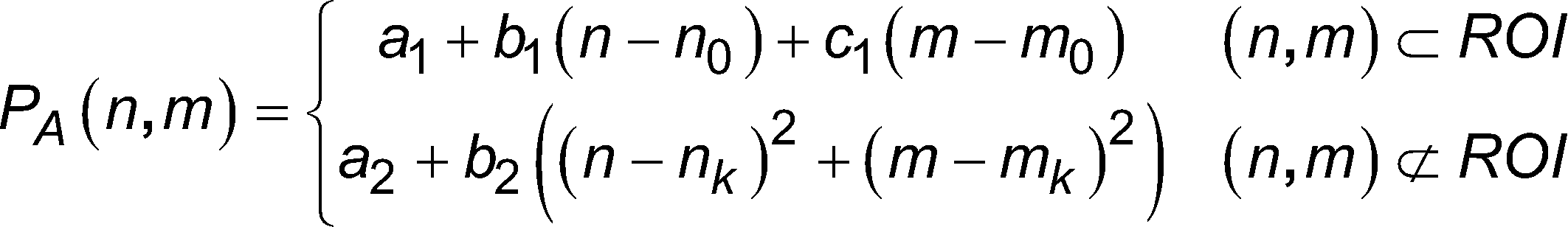
[Math 21]
(Zwölftes modifiziertes Beispiel)(Twelfth modified example)
In den zuvor beschriebenen Ausführungsformen und modifizierten Beispielen ist ein Beispiel einer Form gezeigt, in der die mehreren Linsen 124 als das Linsen-Array 120 des Wellenfrontsensors 12 in Form eines zweidimensionalen Gitters angeordnet sind, wie in
(Dreizehntes modifiziertes Beispiel)(Thirteenth modified example)
In den zuvor beschriebenen Ausführungsformen und modifizierten Beispielen wird eine Größe des Teils A4 der Wellenfront (siehe
Wenn die Breite des Teils A4 der Wellenfront geringfügig größer als eine einzelne Linse 124 ist, wie in
In den in
Aus dem Vorhergehenden ergibt sich, dass n1 größer ist als 1, wenn n1 keine natürliche Zahl ist. In diesem Falle ist es, wie in der zuvor beschriebenen Ausführungsform, möglich, Bestimmung des Endes dahingehend zu machen, ob die Werte Vx und Vy minimal sind oder ob die Werte Vx und Vy kleiner als der vorbestimmte Schwellwert sind. Auch diese Form ist beispielsweise zweckdienlich, wenn die Abbildungsvergrößerung M zwischen dem räumlichen Lichtmodulator 11 und dem Wellenfrontsensor 12 einen Fehlerbereich für den Entwurfswert berücksichtigt. Ferner ist ein numerischer Wert, der durch Formel (5) (Formel (15)) abgeschätzt wird, generell zulässig, selbst im Falle einer Zahl, die keine ganze Zahl ist. Wenn der durch Formel (5) (Formel (15)) abgeschätzte numerische Wert keine ganze Zahl ist, ist es lediglich erforderlich, einen numerischen Wert einer ganzen Zahl, die größer als der numerische Wert ist, als die Breite (die Anzahl an Pixel) des ersten Gebiets B1 festzulegen.From the foregoing, n 1 is larger than 1 when n 1 is not a natural number. In this case, as in the embodiment described above, it is possible to make determination of the end as to whether the values V x and V y are minimum or whether the values V x and V y are smaller than the predetermined threshold. This form is also convenient, for example, when the imaging magnification M between the spatial light modulator 11 and the
(Vierzehntes modifiziertes Beispiel)(Fourteenth modified example)
Obwohl die Schritte S12 bis S18 iterativ ausgeführt werden, während das erste Gebiet B1 des Phasenmusters PA im Schritt S18, der in
(Fünfzehntes modifiziertes Beispiel)(Fifteenth modified example)
In den zuvor beschriebenen Ausführungsformen und modifizierten Beispielen ist ein maximaler Wert einer Verschiebungsbreite zwischen dem ersten Gebiet B1 und der Linse 124, die dem ersten Gebiet B1 entspricht, ±1/2 mal der Anzahl an Pixel w einer Seite des ersten Gebiets B1. Folglich ist die Anzahl an Kombinationen von Positionsbeziehungen zwischen dem ersten Gebiet B1 und der Linse 124, die dem ersten Gebiet B1 entspricht, w×w. Von den w×w Positionsbeziehungen ist die Anzahl an Positionsbeziehungen, in denen die Position des ersten Gebiets B1 vollständig der Position der Linse 124 spricht, genau eins. In den Fällen der (w×w -1) anderen Positionsbeziehungen hat das erste Gebiet B1 den speziellen Verschiebebetrag für jede Positionsbeziehung in der Zeilenrichtung, der Spaltenrichtung oder sowohl der Zeilenals auch der Spaltenrichtung für die Linse 124.In the above-described embodiments and modified examples, a maximum value of a shift width between the first region B1 and the
Daher wird in diesem modifizierten Beispiel im Schritt S12, der in
Eine Mittelposition (slmXi,j, slmYj,j) eines (i, j)-ten ersten Gebiets B1, das in dem Phasenmuster PA in diesem modifizierten Beispiel enthalten ist, wird beispielsweise durch die folgende Formel (22) ausgedrückt.
[Mathe 22]![]()
[Math 22] ![]()
Ein Justierverfahren für eine adaptives Optiksystem, ein adaptives Optiksystem, ein Programm für ein adaptives Optiksystem und ein Speichermedium, das ein Programm für ein adaptives Optiksystem speichert, gemäß einem Aspekt der vorliegenden Erfindung sind nicht auf die zuvor beschriebenen Ausführungsformen eingeschränkt, und es sind diverse andere Modifizierungen möglich. Obwohl beispielsweise ein Kalibriervorgang durch Festlegen, im Voraus, der Größe des ersten Gebiets B1 in den zuvor beschriebenen Ausführungsformen und modifizierten Beispielen ausgeführt ist, kann die Größe des ersten Gebiets B1 variabel sein.
Ferner ist der Fall gezeigt, in welchem das adaptive Optiksystem einen einzelnen räumlichen Lichtmodulator in den zuvor beschriebenen Ausführungsformen und modifizierten Beispielen enthält, aber das adaptive Optiksystem kann mehrere räumliche Lichtmodulatoren aufweisen, die optisch in Reihe geschaltet sind. In diesem Falle ist es möglich, eine Kalibrierung eines einzelnen räumlichen Lichtmodulators und eines Wellenfrontsensors auszuführen, indem bewirkt wird, dass der eine räumliche Lichtmodulator ein spezielles Phasenmuster PA für die Kalibrierung anzeigt und ein weiterer räumlicher Lichtmodulator beispielsweise ein im Wesentlichen gleichförmiges Phasenmuster anzeigt. Es ist möglich, eine Kalibrierung aller räumlichen Lichtmodulatoren und eines Wellenfrontsensors auszuführen, indem der zuvor beschriebene Vorgang an jedem von mehreren räumlichen Lichtmodulatoren ausgeführt wird. Selbst wenn die mehreren räumlichen Lichtmodulatoren in einem adaptiven Optiksystem, das mehrere räumliche Lichtmodulator enthält, optisch parallel gekoppelt sind, ist es möglich, die Kalibrierung aller räumlicher Lichtmodulatoren und des Wellenfrontsensors und die gegenseitige Zuordnung zwischen den mehreren räumlichen Lichtmodulator auszuführen.Furthermore, the case is shown in which the adaptive optics system includes a single spatial light modulator in the above-described embodiments and modified examples, but the adaptive optics system may include multiple spatial light modulators optically connected in series. In this case, it is possible to perform calibration of a single spatial light modulator and a wavefront sensor by causing the one spatial light modulator to have a specific phase pattern P A for calibration and another spatial light modulator displays a substantially uniform phase pattern, for example. It is possible to perform calibration of all spatial light modulators and a wavefront sensor by performing the above-described operation on each of a plurality of spatial light modulators. Even when the plurality of spatial light modulators are optically coupled in parallel in an adaptive optics system including a plurality of spatial light modulators, it is possible to perform calibration of all spatial light modulators and the wavefront sensor and mutual association between the plurality of spatial light modulators.
Industrielle AnwendbarkeitIndustrial applicability
Gemäß einem Justierverfahren für ein adaptives Optiksystem, einem adaptiven Optiksystem, einem Programm für ein adaptives Optiksystem und einem Speichermedium, das ein Programm für ein adaptives Optiksystem speichert, entsprechend einem Aspekt der vorliegenden Erfindung ist es möglich, eine Zuordnungsrelation zwischen einem Phasenmuster, das in einem Wellenfrontsensor gemessen wird, und einem Kompensationsphasenmuster, das in einem räumlichen Lichtmodulator angezeigt wird, schnell und mit hoher Genauigkeit zu justieren.According to an adjustment method for an adaptive optics system, an adaptive optics system, a program for an adaptive optics system, and a storage medium storing a program for an adaptive optics system according to an aspect of the present invention, it is possible to adjust a correspondence relation between a phase pattern measured in a wavefront sensor and a compensation phase pattern displayed in a spatial light modulator quickly and with high accuracy.
Liste der BezugszeichenList of reference symbols
- 1010
- Adaptives OptiksystemAdaptive optics system
- 1111
- Räumlicher LichtmodulatorSpatial light modulator
- 11a11a
- ModulationsoberflächeModulation surface
- 11b11b
- Pixelpixel
- 1212
- WellenfrontsensorWavefront sensor
- 1313
- SteuereinheitControl unit
- 13a13a
- SpeichergebietStorage area
- 13b13b
- MustererzeugungseinheitPattern generation unit
- 13c13c
- BerechnungsverarbeitungseinheitCalculation processing unit
- 1414
- StrahlteilerBeam splitter
- 15,1615,16
- ÜbertragungslinseTransfer lens
- 1717
- SteuerschaltungseinheitControl circuit unit
- 1818
- Optisches ErfassungselementOptical detection element
- 120120
- Linsen-ArrayLens array
- 122122
- BildsensorImage sensor
- 122a122a
- LichtempfangsoberflächeLight receiving surface
- 122b122b
- Pixelpixel
- 124124
- Linselens
- B1B1
- Erstes GebietFirst area
- B2B2
- zweites Gebietsecond area
- DA, DBDA, DB
- Daten der LichtintensitätsverteilungLight intensity distribution data
- LaThe
- optisches Bildoptical image
- PP
- konvergierender Fleck bzw. Leuchtfleckconverging spot or luminous spot
- PA, PBPB, PG
- PhasenmusterPhase pattern
- R0 bis R4R0 to R4
- Berechnungsgebiet für EigenschaftsquantitätenCalculation area for property quantities
Claims (9)
Applications Claiming Priority (3)
| Application Number | Priority Date | Filing Date | Title |
|---|---|---|---|
| JP2013119852 | 2013-06-06 | ||
| JP2013-119852 | 2013-06-06 | ||
| PCT/JP2014/064294 WO2014196448A1 (en) | 2013-06-06 | 2014-05-29 | Adjustment method for adaptive optics system, adaptive optics system, and storage medium storing program for adaptive optics system |
Publications (2)
| Publication Number | Publication Date |
|---|---|
| DE112014002683T5 DE112014002683T5 (en) | 2016-03-10 |
| DE112014002683B4 true DE112014002683B4 (en) | 2024-04-18 |
Family
ID=52008094
Family Applications (1)
| Application Number | Title | Priority Date | Filing Date |
|---|---|---|---|
| DE112014002683.2T Active DE112014002683B4 (en) | 2013-06-06 | 2014-05-29 | Adjustment method for adaptive optics system, adaptive optics system and storage medium storing a program for an adaptive optics system |
Country Status (6)
| Country | Link |
|---|---|
| US (1) | US9594245B2 (en) |
| JP (1) | JP6259825B2 (en) |
| KR (1) | KR102128642B1 (en) |
| CN (1) | CN105264428B (en) |
| DE (1) | DE112014002683B4 (en) |
| WO (1) | WO2014196448A1 (en) |
Families Citing this family (24)
| Publication number | Priority date | Publication date | Assignee | Title |
|---|---|---|---|---|
| WO2014196450A1 (en) * | 2013-06-06 | 2014-12-11 | 浜松ホトニクス株式会社 | Correspondence relation specifying method for adaptive optics system, wavefront distortion compensation method, adaptive optics system, and storage medium storing program for adaptive optics system |
| EP2908341B1 (en) * | 2014-02-18 | 2018-07-11 | ams AG | Semiconductor device with surface integrated focusing element |
| JP6768444B2 (en) * | 2016-10-14 | 2020-10-14 | 浜松ホトニクス株式会社 | Laser processing equipment and operation check method |
| IL251636B (en) | 2017-04-06 | 2018-02-28 | Yoav Berlatzky | A system and method for a coherent camera |
| US20180301484A1 (en) * | 2017-04-17 | 2018-10-18 | Semiconductor Components Industries, Llc | Image sensors with high dynamic range and autofocusing hexagonal pixels |
| JP6969164B2 (en) * | 2017-05-31 | 2021-11-24 | 株式会社リコー | Evaluation device, evaluation program and evaluation method |
| KR20190054353A (en) | 2017-11-13 | 2019-05-22 | 한국 천문 연구원 | General-purpose adaptive optics |
| JP6924163B2 (en) * | 2018-03-27 | 2021-08-25 | 株式会社日立製作所 | Imaging device, imaging module and imaging method |
| CN110501826B (en) * | 2018-05-18 | 2021-09-07 | 中国科学院上海光学精密机械研究所 | A method of improving beam quality based on phase carrier |
| EP3620763A1 (en) * | 2018-09-07 | 2020-03-11 | Boegli-Gravures S.A. | Adaptive laser-beam shaping |
| CN109358030B (en) * | 2018-11-26 | 2020-10-30 | 浙江大学 | Multicolor super-resolution microscope system with automatic alignment function |
| CN109520712B (en) * | 2018-12-03 | 2021-08-17 | 江苏慧光电子科技有限公司 | Optical detection method, system and optical device manufacturing system |
| CN109683312B (en) * | 2019-01-22 | 2021-03-12 | 中国工程物理研究院激光聚变研究中心 | Method for adjusting image transfer relationship of adaptive optical system |
| FR3092396B1 (en) * | 2019-01-31 | 2021-04-09 | Centre Nat Rech Scient | Density gradient filter optical wave surface control system |
| CN111609995B (en) * | 2019-02-26 | 2025-07-22 | 弗提图德萨沃有限公司 | Optical mold assembling and adjusting test method and device |
| US11662597B2 (en) * | 2019-07-03 | 2023-05-30 | Texas Instruments Incorporated | Homogenizing lens array for display imaging |
| CN112161584A (en) * | 2020-10-27 | 2021-01-01 | 龚海 | A wavefront three-dimensional microscope based on tilt modulation of illumination light |
| CN113295286A (en) * | 2021-05-20 | 2021-08-24 | 中国科学院西安光学精密机械研究所 | shack-Hartmann wavefront sensor measuring system and phase recovery method |
| CN113534255B (en) | 2021-07-07 | 2024-07-16 | 南方海洋科学与工程广东省实验室(湛江) | Method for self-adaptive expression of discontinuous surface in any form |
| CN113267909B (en) * | 2021-07-19 | 2021-10-08 | 军事科学院系统工程研究院网络信息研究所 | Peep-proof display method based on wave front distortion compensation |
| WO2024030902A1 (en) * | 2022-08-01 | 2024-02-08 | California Institute Of Technology | Complex-wavefront photonic transceiver processor |
| CN115685565B (en) * | 2022-08-05 | 2024-07-26 | 华侨大学 | A method and device for controlling a complex light field passing through a scattering medium |
| KR102841979B1 (en) * | 2022-09-15 | 2025-08-04 | 서울대학교산학협력단 | Apparatus and method for optical detection based on adaptive optical segmentation |
| CN119803273B (en) * | 2025-03-13 | 2025-07-11 | 中国科学院长春光学精密机械与物理研究所 | Compensation device design method and compensation detection device for complex curved optical elements |
Citations (2)
| Publication number | Priority date | Publication date | Assignee | Title |
|---|---|---|---|---|
| US6827442B2 (en) | 2001-09-12 | 2004-12-07 | Denwood F. Ross | Ophthalmic wavefront measuring devices |
| DE112009000369T5 (en) | 2008-02-14 | 2011-01-13 | Hamamatsu Photonics K.K., Hamamatsu-shi | observer |
Family Cites Families (17)
| Publication number | Priority date | Publication date | Assignee | Title |
|---|---|---|---|---|
| JPH0915057A (en) * | 1995-06-26 | 1997-01-17 | Mitsubishi Electric Corp | Wavefront sensor and wavefront measuring method |
| US6771417B1 (en) * | 1997-08-01 | 2004-08-03 | Carl Zeiss Jena Gmbh | Applications of adaptive optics in microscopy |
| GB0314444D0 (en) * | 2003-06-20 | 2003-07-23 | Univ Heriot Watt | Novel wavefront sensor |
| US7333215B2 (en) * | 2003-06-25 | 2008-02-19 | The Boeing Company | Adaptive optics control system |
| JP4531431B2 (en) * | 2004-04-02 | 2010-08-25 | 浜松ホトニクス株式会社 | Wavefront compensation device, wavefront compensation method, program, and recording medium |
| WO2006035775A1 (en) * | 2004-09-27 | 2006-04-06 | Hamamatsu Photonics K.K. | Spatial light modulator, optical processor, coupling prism and method for using coupling prism |
| EP1910996A1 (en) * | 2005-02-23 | 2008-04-16 | Lyncee Tec S.A. | Wave front sensing method and apparatus |
| WO2007070006A1 (en) * | 2005-12-13 | 2007-06-21 | Agency For Science, Technology And Research | Optical wavefront sensor |
| US8451427B2 (en) * | 2007-09-14 | 2013-05-28 | Nikon Corporation | Illumination optical system, exposure apparatus, optical element and manufacturing method thereof, and device manufacturing method |
| JP2009162614A (en) * | 2008-01-07 | 2009-07-23 | Mitsubishi Electric Corp | Optical wavefront measuring device |
| JP5692969B2 (en) * | 2008-09-01 | 2015-04-01 | 浜松ホトニクス株式会社 | Aberration correction method, laser processing method using this aberration correction method, laser irradiation method using this aberration correction method, aberration correction apparatus, and aberration correction program |
| US8551730B2 (en) * | 2008-10-24 | 2013-10-08 | The Regents Of The University Of California | Use of a reference source with adaptive optics in biological microscopy |
| JP5599563B2 (en) * | 2008-12-25 | 2014-10-01 | 浜松ホトニクス株式会社 | Light control device and light control method |
| JP5289173B2 (en) * | 2009-05-07 | 2013-09-11 | 三菱電機株式会社 | Wavefront sensor |
| JP2012037572A (en) * | 2010-08-03 | 2012-02-23 | Hamamatsu Photonics Kk | Optical system for shaping laser beam and controlling wave front |
| US8237835B1 (en) * | 2011-05-19 | 2012-08-07 | Aeon Imaging, LLC | Confocal imaging device using spatially modulated illumination with electronic rolling shutter detection |
| JP5919100B2 (en) * | 2012-06-04 | 2016-05-18 | 浜松ホトニクス株式会社 | ADJUSTING OPTICAL SYSTEM ADJUSTING METHOD AND COMPENSATING OPTICAL SYSTEM |
-
2014
- 2014-05-29 DE DE112014002683.2T patent/DE112014002683B4/en active Active
- 2014-05-29 US US14/895,588 patent/US9594245B2/en active Active
- 2014-05-29 WO PCT/JP2014/064294 patent/WO2014196448A1/en not_active Ceased
- 2014-05-29 CN CN201480031849.3A patent/CN105264428B/en active Active
- 2014-05-29 KR KR1020157037214A patent/KR102128642B1/en not_active Expired - Fee Related
- 2014-05-29 JP JP2015521417A patent/JP6259825B2/en active Active
Patent Citations (2)
| Publication number | Priority date | Publication date | Assignee | Title |
|---|---|---|---|---|
| US6827442B2 (en) | 2001-09-12 | 2004-12-07 | Denwood F. Ross | Ophthalmic wavefront measuring devices |
| DE112009000369T5 (en) | 2008-02-14 | 2011-01-13 | Hamamatsu Photonics K.K., Hamamatsu-shi | observer |
Non-Patent Citations (2)
| Title |
|---|
| AWWAL, A. [et al.]: Characterization and Operation of a Liquid Crystal Adaptive Optics Phoropter. In: Proc. of SPIE, Vol. 5169, 2003, Pages 104 – 122, ISSN 1996 - 756X |
| Porter [et al.]: Adaptive Optics for Vision Science. Hoboken: Wiley Interscience, 2006. Chapter 18, pp. 496-499. - ISBN 9780471679417 |
Also Published As
| Publication number | Publication date |
|---|---|
| DE112014002683T5 (en) | 2016-03-10 |
| JPWO2014196448A1 (en) | 2017-02-23 |
| KR102128642B1 (en) | 2020-06-30 |
| JP6259825B2 (en) | 2018-01-10 |
| WO2014196448A1 (en) | 2014-12-11 |
| KR20160016962A (en) | 2016-02-15 |
| CN105264428A (en) | 2016-01-20 |
| US9594245B2 (en) | 2017-03-14 |
| CN105264428B (en) | 2018-06-29 |
| US20160131901A1 (en) | 2016-05-12 |
Similar Documents
| Publication | Publication Date | Title |
|---|---|---|
| DE112014002683B4 (en) | Adjustment method for adaptive optics system, adaptive optics system and storage medium storing a program for an adaptive optics system | |
| DE112014002694B4 (en) | Method for determining a matching relationship for an adaptive optics system, method for compensating a wavefront distortion, adaptive optics system and storage medium for storing a program for an adaptive optics system | |
| DE112013002773B4 (en) | Method for adjusting a compensating optical system and compensating optical system | |
| DE112014002681T5 (en) | An angular misalignment method for adaptive optics, an image magnification acquisition method for adaptive optics, and an adaptive optics system | |
| DE112014002729T5 (en) | A method of determining a correspondence relationship for an adaptive optics system, an adaptive optics system, and a storage medium for storing an adaptive optics system program | |
| EP0167877B1 (en) | Apparatus for imaging sections of the human eye | |
| DE112009000369B4 (en) | Observation device | |
| DE102011114500B4 (en) | microscope device | |
| DE3886893T2 (en) | Device for three-dimensional measurement of a shape. | |
| EP3058414B1 (en) | Scanning microscope and method for determining the point spread function (psf) of a scanning microscope | |
| DE112014001147B4 (en) | Fluorescence receiving device and method for receiving fluorescence | |
| DE102010016997B4 (en) | Inspection system and method with multiple image phase shift analysis | |
| EP3887754B1 (en) | Method and interferometer for determining an input phase and/or an input amplitude of an input light field | |
| DE60225320T2 (en) | SECONDARY SYSTEM AND ROOM FILTER | |
| DE10257766A1 (en) | Method for setting a desired optical property of a projection lens and microlithographic projection exposure system | |
| WO2018172161A1 (en) | Microscope and method for imaging an object | |
| DE10202738B4 (en) | Phase shift strip analysis method and apparatus using this method | |
| DE102017215976B4 (en) | Method for measuring a laser beam | |
| DE112016001974T5 (en) | Method for focal length and rotation angle measurement using a Fabry-Pérot etalon | |
| DE102014010667B4 (en) | Method and device for measuring the shape of a wavefront of an optical radiation field | |
| DE102021108238A1 (en) | Computer-implemented method, procedure, measuring device and computer program product | |
| DE102004056723A1 (en) | Digital camera`s geometry calibrating device for e.g. space-related purposes, has controllable diffractive optical unit producing temporal sequence of diffraction patterns, whose ideal intensity distribution in ideal image plane is known | |
| EP4630883A1 (en) | Field-dependent aberration correction in coherent imaging, in particular digital holography | |
| DE102021214142A1 (en) | Method for calibrating a manipulable optical module | |
| DE102021129821B4 (en) | DETERMINATION OF A WAVEFRONT SLOPE OF A LIGHT BASED ON ANGLE DEPENDENT TRANSMISSION |
Legal Events
| Date | Code | Title | Description |
|---|---|---|---|
| R012 | Request for examination validly filed | ||
| R016 | Response to examination communication | ||
| R018 | Grant decision by examination section/examining division | ||
| R020 | Patent grant now final |