DE112008000565T5 - shield shell - Google Patents
shield shell Download PDFInfo
- Publication number
- DE112008000565T5 DE112008000565T5 DE112008000565T DE112008000565T DE112008000565T5 DE 112008000565 T5 DE112008000565 T5 DE 112008000565T5 DE 112008000565 T DE112008000565 T DE 112008000565T DE 112008000565 T DE112008000565 T DE 112008000565T DE 112008000565 T5 DE112008000565 T5 DE 112008000565T5
- Authority
- DE
- Germany
- Prior art keywords
- shielding
- shell
- conductive
- shell body
- tubular
- Prior art date
- Legal status (The legal status is an assumption and is not a legal conclusion. Google has not performed a legal analysis and makes no representation as to the accuracy of the status listed.)
- Withdrawn
Links
- 229920005989 resin Polymers 0.000 claims abstract description 17
- 239000011347 resin Substances 0.000 claims abstract description 17
- 230000009975 flexible effect Effects 0.000 claims abstract description 5
- 230000002093 peripheral effect Effects 0.000 claims description 7
- RYGMFSIKBFXOCR-UHFFFAOYSA-N Copper Chemical compound [Cu] RYGMFSIKBFXOCR-UHFFFAOYSA-N 0.000 description 15
- 229910052802 copper Inorganic materials 0.000 description 13
- 239000010949 copper Substances 0.000 description 13
- UQMRAFJOBWOFNS-UHFFFAOYSA-N butyl 2-(2,4-dichlorophenoxy)acetate Chemical compound CCCCOC(=O)COC1=CC=C(Cl)C=C1Cl UQMRAFJOBWOFNS-UHFFFAOYSA-N 0.000 description 11
- 229920000049 Carbon (fiber) Polymers 0.000 description 7
- 239000004917 carbon fiber Substances 0.000 description 7
- 230000000694 effects Effects 0.000 description 6
- VNWKTOKETHGBQD-UHFFFAOYSA-N methane Chemical compound C VNWKTOKETHGBQD-UHFFFAOYSA-N 0.000 description 6
- 229920001707 polybutylene terephthalate Polymers 0.000 description 6
- 229910052782 aluminium Inorganic materials 0.000 description 3
- XAGFODPZIPBFFR-UHFFFAOYSA-N aluminium Chemical compound [Al] XAGFODPZIPBFFR-UHFFFAOYSA-N 0.000 description 3
- 238000002156 mixing Methods 0.000 description 3
- 229910000881 Cu alloy Inorganic materials 0.000 description 2
- 238000005266 casting Methods 0.000 description 2
- 239000011248 coating agent Substances 0.000 description 2
- 238000000576 coating method Methods 0.000 description 2
- 229910052751 metal Inorganic materials 0.000 description 2
- 239000002184 metal Substances 0.000 description 2
- 238000000034 method Methods 0.000 description 2
- 238000000465 moulding Methods 0.000 description 2
- 238000012216 screening Methods 0.000 description 2
- 238000007789 sealing Methods 0.000 description 2
- 210000002105 tongue Anatomy 0.000 description 2
- BUHVIAUBTBOHAG-FOYDDCNASA-N (2r,3r,4s,5r)-2-[6-[[2-(3,5-dimethoxyphenyl)-2-(2-methylphenyl)ethyl]amino]purin-9-yl]-5-(hydroxymethyl)oxolane-3,4-diol Chemical compound COC1=CC(OC)=CC(C(CNC=2C=3N=CN(C=3N=CN=2)[C@H]2[C@@H]([C@H](O)[C@@H](CO)O2)O)C=2C(=CC=CC=2)C)=C1 BUHVIAUBTBOHAG-FOYDDCNASA-N 0.000 description 1
- 229910000838 Al alloy Inorganic materials 0.000 description 1
- 239000004411 aluminium Substances 0.000 description 1
- 238000004891 communication Methods 0.000 description 1
- 238000010276 construction Methods 0.000 description 1
- 230000007423 decrease Effects 0.000 description 1
- 238000011835 investigation Methods 0.000 description 1
- 239000000463 material Substances 0.000 description 1
- -1 polybutylene terephthalate Polymers 0.000 description 1
- 239000010935 stainless steel Substances 0.000 description 1
- 229910001220 stainless steel Inorganic materials 0.000 description 1
- 229920003002 synthetic resin Polymers 0.000 description 1
- 239000000057 synthetic resin Substances 0.000 description 1
Classifications
-
- H—ELECTRICITY
- H01—ELECTRIC ELEMENTS
- H01R—ELECTRICALLY-CONDUCTIVE CONNECTIONS; STRUCTURAL ASSOCIATIONS OF A PLURALITY OF MUTUALLY-INSULATED ELECTRICAL CONNECTING ELEMENTS; COUPLING DEVICES; CURRENT COLLECTORS
- H01R13/00—Details of coupling devices of the kinds covered by groups H01R12/70 or H01R24/00 - H01R33/00
- H01R13/648—Protective earth or shield arrangements on coupling devices, e.g. anti-static shielding
- H01R13/658—High frequency shielding arrangements, e.g. against EMI [Electro-Magnetic Interference] or EMP [Electro-Magnetic Pulse]
- H01R13/6591—Specific features or arrangements of connection of shield to conductive members
- H01R13/6592—Specific features or arrangements of connection of shield to conductive members the conductive member being a shielded cable
- H01R13/6593—Specific features or arrangements of connection of shield to conductive members the conductive member being a shielded cable the shield being composed of different pieces
-
- H—ELECTRICITY
- H01—ELECTRIC ELEMENTS
- H01R—ELECTRICALLY-CONDUCTIVE CONNECTIONS; STRUCTURAL ASSOCIATIONS OF A PLURALITY OF MUTUALLY-INSULATED ELECTRICAL CONNECTING ELEMENTS; COUPLING DEVICES; CURRENT COLLECTORS
- H01R13/00—Details of coupling devices of the kinds covered by groups H01R12/70 or H01R24/00 - H01R33/00
- H01R13/73—Means for mounting coupling parts to apparatus or structures, e.g. to a wall
- H01R13/74—Means for mounting coupling parts in openings of a panel
Landscapes
- Shielding Devices Or Components To Electric Or Magnetic Fields (AREA)
- Details Of Connecting Devices For Male And Female Coupling (AREA)
Abstract
Eine Abschirmschale, aufweisend:
einen Schalenkörper aus leitfähigem Harz und von Rohrform, der in der Lage ist, einen leitfähigen Pfad zu umgeben, in welchem ein erstes Ende von beiden Enden in Axialrichtung fest an einem Anschluss eines rohrförmigen und flexiblen Abschirmteils befestigt ist, welches den leitfähigen Pfad umgibt, während ein zweites Ende der beiden Enden an einem Abschirmgehäuse eines Geräts angebracht ist; und
einen metallischen leitfähigen Körper in dem Schalenkörper, der in dem ersten Ende des Schalenkörpers von der Oberfläche des Schalenkörpers frei liegt, um mit dem Abschirmteil verbunden zu sein, und in dem zweiten Ende des Schalenkörpers von dieser Oberfläche frei liegt, um mit dem Schirmgehäuse verbunden zu sein.A shielding shell, comprising:
a shell body of conductive resin and of tubular shape capable of surrounding a conductive path in which a first end of both ends is fixed in the axial direction fixed to a terminal of a tubular and flexible shielding member surrounding the conductive path a second end of the two ends is attached to a shield case of a device; and
a metallic conductive body in the shell body exposed in the first end of the shell body from the surface of the shell body to be connected to the shielding member, and exposed in the second end of the shell body from this surface to be connected to the shielding housing be.
Description
Technisches GebietTechnical area
Die vorliegende Erfindung betrifft eine Abschirmschale.The The present invention relates to a shielding shell.
Stand der TechnikState of the art
Patentliteratur 1 beschreibt einen Aufbau, bei dem ein Anschluss eines rohrförmigen Abschirmteils, bestehend aus einem vernetzten Draht, mit einem Abschirmgehäuse eines Geräts über eine elektrisch leitfähige und rohrförmige Abschirmschale verbunden ist. Was diese Arten von Abschirmschalen betrifft, wurden welche aus Aluminiumformguss verwendet, jedoch wurde mit Blick auf das Gewicht eine Abschirmschale aus leitfähigem Harz, erhalten durch Einbetten von Kohlenstofffasern in ein Harz, beispielsweise PBT, als Alternative angesehen.
- [Patentliteratur
1]: ungeprüfte
japanische Patentveröffentlichung Nr. H10-241792
- [Patent Literature 1]: unchecked
Japanese Patent Publication No. H10-241792
Beschreibung der ErfindungDescription of the invention
Von der Erfindung zu lösende AufgabeTo be solved by the invention task
Aufgrund des hohen spezifischen Durchgangswiderstands ist es jedoch bei einem leitfähigem Harz ein Problem, dass es geringe Abschirmleistung im niederfrequenten Bereich zeigt, und eine Gegenmaßnahme wird somit erwartet. Diese Erfindung wurde basierend auf den obigen Umständen gemacht und ihre Aufgabe ist es, die Abschirmleistung in einem niederfrequenten Bereich zu verbessern.by virtue of However, the high volume resistivity is at one Conductive resin has a problem that it has low shielding performance in the low frequency range, and a countermeasure is thus expected. This invention has been based on the above Circumstances and their job is to provide the shielding performance to improve in a low frequency area.
Mittel zur Lösung der AufgabeMeans of solving the task
Als ein Mittel zur Lösung der obigen Aufgabe weist eine Abschirmschale gemäß der vorliegenden Erfindung auf: einen Schalenkörper aus einem leitfähigen Harz mit Rohrform, welche in der Lage ist, einen leitfähigen Pfad zu umgeben, wobei ein erstes Ende von beiden Enden fest an einem Anschluss eines rohrförmigen und flexiblen Abschirmteils angebracht ist, das den leitfähigen Pfad umgibt, während ein zweites Ende der beiden Enden an einem Abschirmgehäuse eines Geräts angebracht ist; und einen metallischen leitfähigen Körper, der in dem Schalenkörper angeordnet ist und im ersten Ende des Schalenkörpers zur Oberfläche des Schalenkörpers frei liegt, um mit dem Abschirmteil verbunden zu sein, während er im zweiten Ende des Schalenkörpers an der Oberfläche des Schalenkörpers frei liegt, um mit dem Abschirmgehäuse verbunden zu sein.When A means for achieving the above object has a shielding shell According to the present invention, a shell body of a conductive resin having a tubular shape, which is in the Able to surround a conductive path, taking a first end of both ends fixed to a port of a tubular and flexible shielding member is attached, which is the conductive Path surrounds while a second end of both ends attached to a shield case of a device is; and a metallic conductive body, which is arranged in the shell body and in the first end of the shell body to the surface of the shell body free is located to be connected to the shielding part while he in the second end of the shell body on the surface the shell body is exposed to the shielding to be connected.
Auswirkungen der ErfindungEffects of the invention
Ein Abschirmteil und ein Abschirmgehäuse sind miteinander durch einen metallischen leitfähigen Körper mit geringem elektrischen Widerstand verbunden und damit wird eine ausgezeichnete Abschirmleistung in einer Abschirmschale in einem niederfrequenten Bereich erreicht.One Shielding part and a shielding are mutually by a metallic conductive body with low connected to electrical resistance and thus will be an excellent Shielding power in a shielding shell in a low-frequency Area reached.
Kurze Beschreibung der ZeichnungShort description of the drawing
BezugszeichenbeschreibungReference numeral Description
-
10 ... Gerät (Invertervorrichtung),11 ... Abschirmgehäuse,21 ... Draht (leitfähiger Pfad),22 ... Abschirmteil,24 ... Anschluss (leitfähiger Pfad),40 ... Abschirmschale,41 ... Schalenkörper,46 ... leitfähiger Körper.10 ... device (inverter device),11 ... shielding housing,21 ... wire (conductive path),22 ... shielding part,24 ... connection (conductive path),40 ... shielding shell,41 ... bowl body,46 ... conductive body.
Beste Weise zur Durchführung der ErfindungBest way to carry the invention
Nachfolgend
wird Bezug nehmend auf die
Die
Invertervorrichtung
Wie
in
Der
Kabelbaum
Der
Verbinder
Das
Verbindergehäuse
Die
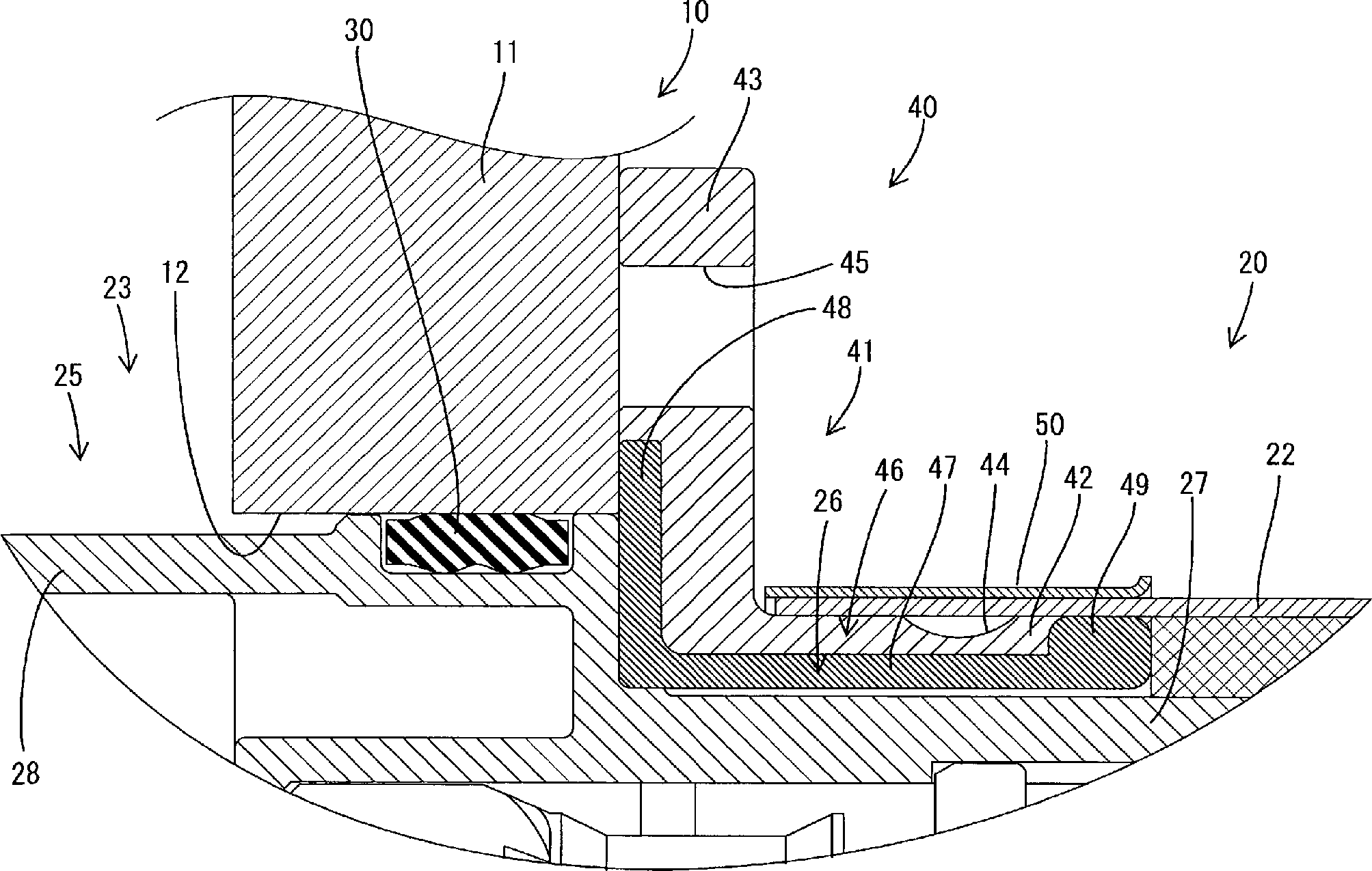
Abschirmschale
Der
Schalenkörper
Gemäß
Das
Vorderende des Abschirmteils
Da
drei Kabel
Folglich
ist der leitfähige Pfad vom Anschlussteil des Kabels
Die
Demgegenüber
zeigt
Wie
erläutert wird die Abschirmschale
Zusätzlich
erstreckt sich der leitfähige Körper
Weiterhin
ist das Verbindungsende des leitfähigen Körpers
<Ausführungsform 2><embodiment 2>
Gemäß den
Der verbleibende Aufbau ist nahezu gleich wie in Ausführungsform 1 und somit bezeichnen gleiche Bezugszeichen gleiche Teile und werden nicht noch einmal wiederholt beschrieben.Of the remaining structure is almost the same as in embodiment 1 and thus reference numerals denote like parts and will be not described again.
Gemäß der
vorliegenden Ausführungsform ist das Paar von leitfähigen
Körpern
<Ausführungsform 3><embodiment 3>
Gemäß
Der verbleibende Aufbau ist nahezu gleich wie in Ausführungsform 1 und somit bezeichnen gleiche Bezugszeichen gleiche Teile und eine nochmalige wiederholte Beschreibung erfolgt nicht.Of the remaining structure is almost the same as in embodiment 1 and thus reference numerals denote like parts and a Repeated description is not repeated.
Bei
dieser Ausführungsform sind 3 leitfähige Körper
<Vergleich der Abschirmleistung><comparison the shielding capacity>
Wie
in der Grafik von
Auch in einem Bereich von 10 MHz bis 100 MHz lässt sich erkennen, dass die Abschirmleistung umso mehr zunimmt, um so mehr Kupferbänder angebracht werden.Also in a range from 10 MHz to 100 MHz, it can be seen that the shielding power increases all the more, the more copper bands be attached.
<Andere Ausführungsform><Others embodiment>
Obgleich Ausführungsformen der vorliegenden Erfindung oben unter Bezugnahme auf die beigefügte Zeichnung beschrieben worden sind, versteht sich, dass die Erfindung nicht auf diese exakten Ausführungsformen beschränkt ist und beispielsweise können auch die nachfolgenden Ausführungsformen im Umfang der vorliegenden Erfindung liegend gesehen werden.
- (1) Der leitfähige Körper ist nicht auf eine Stabform beschränkt und kann zylindrische Form haben. In diesem Fall kann eine Form möglich sein, welche die äußere Umfangsoberfläche des Schalenkörpers abdeckt, die innere Umfangsoberfläche des Schalenkörpers abdeckt und den leitfähigen Körper anders als an seinen beiden Enden in Axialrichtung an der Innenseite des Schalenkörpers einbettet.
- (2) Die Mittel zum Anbringen des leitfähigen Körpers am Schalenkörper sind nicht auf das Einsetzgießen beschränkt und der leitfähige Körper und der Schalenkörper können separat hergestellt und zusammengefügt werden. Das Zusammenfügverfahren kann für leitfähige Körper anderer Formgebungen und Ausgestaltungen verwendet werden.
- (3) Der leitfähige Körper ist nicht auf einen ohne Flexibilität beschränkt und kann von einer Bauart sein, bei der ein flexibles und metallisches Band oder eine Schicht (beispielsweise aus Kupfer) an der Oberfläche des Schalenkörpers angebracht ist.
- (4) Eine Mehrzahl leitfähiger Körper (mehr als vier) kann in einem Schalenkörper verwendet sein.
- (5) In den obigen Ausführungsformen wurde der Fall beschrieben, wo das Gehäuse mit dem Anschluss hierin im Inneren der Abschirmschale eingesetzt ist; die vorliegende Erfindung kann jedoch auch bei einem Fall angewendet werden, wo der Anschlussteil des Kabels, der die Abschirmschale durchtritt, mit der Anschlussklemme im Abschirmgehäuse verbunden ist, ohne dass das Gehäuse innerhalb der Abschirmschale aufgenommen ist.
- (6)
11 zeigt den Aufbau, bei dem die Abschirmschale40 gemäß der vorliegenden Erfindung in ein Hybridfahrzeug (entsprechend einem Fahrzeug)60 eingebaut ist. Das Hybridfahrzeug60 ist aus gestattet mit einer Batterie62 , der Invertervorrichtung10 , einem Motor61 und einem Antrieb63 welche untereinander mit dem Kabelbaum20 verbunden sind. Die Abschirmschale40 kann an dem Verbindungsteil des Kabelbaums20 angebracht sein, welches die Invertervorrichtung10 und den Motor61 verbindet. Ein Gleichstrom von der Batterie62 wird von der Invertervorrichtung10 in einen dreiphasigen Wechselstrom gewandelt und dann dem Motor61 zugeführt. Die Abschirmschale40 kann am Verbindungsteil des Kabelbaums20 je nach Bedarf angebracht werden. - (7) Der leitfähige Körper ist nicht auf Kupfer oder eine Kupferlegierung beschränkt und kann aus einem beliebigen Metall sein, beispielsweise rostfreiem Stahl, Aluminium oder einer Aluminiumlegierung, je nach Bedarf.
- (8) Eine Mehrzahl von leitfähigen Körpern muss nicht notwendigerweise symmetrisch angeordnet werden, sondern kann bei Bedarf auch an beliebigen Positionen angeordnet werden.
- (9) Die Abschirmschale kann am Kabelbaum angebracht werden, der in einem elektrischen Fahrzeug verlegt ist.
- (1) The conductive body is not limited to a rod shape and may have a cylindrical shape. In this case, a shape may be possible which covers the outer peripheral surface of the shell body, covers the inner peripheral surface of the shell body, and embeds the conductive body in the axial direction on the inside of the shell body other than at both its ends.
- (2) The means for attaching the conductive body to the shell body are not limited to the insert molding, and the conductive body and the shell body can be manufactured and assembled separately. The joining method can be used for conductive bodies of other shapes and configurations.
- (3) The conductive body is not limited to one without flexibility, and may be of a type in which a flexible and metallic band or layer (of copper, for example) is attached to the surface of the shell body.
- (4) A plurality of conductive bodies (more than four) may be used in a shell body.
- (5) In the above embodiments, the case where the housing having the terminal therein is inserted inside the shield shell has been described; However, the present invention can also be applied to a case where the terminal part of the cable passing through the shield shell is connected to the terminal in the shield case without accommodating the housing inside the shield shell.
- (6)
11 shows the structure in which the shielding shell40 according to the present invention in a hybrid vehicle (corresponding to a vehicle)60 is installed. The hybrid vehicle60 is equipped with a battery62 , the inverter device10 a motor61 and a drive63 which each other with the wiring harness20 are connected. The shielding shell40 can at the connection part of the wiring harness20 be attached, which is the inverter device10 and the engine61 combines. A direct current from the battery62 is from the inverter device10 converted into a three-phase alternating current and then the motor61 fed. The shielding shell40 can at the connection part of the wiring harness20 be attached as needed. - (7) The conductive body is not limited to copper or a copper alloy, and may be made of any metal such as stainless steel, aluminum or an aluminum alloy as needed.
- (8) A plurality of conductive bodies do not necessarily have to be arranged symmetrically, but may be arranged at arbitrary positions if necessary.
- (9) The shield shell can be attached to the wiring harness laid in an electric vehicle.
ZUSAMMENFASSUNGSUMMARY
Eine
Abschirmschale (
ZITATE ENTHALTEN IN DER BESCHREIBUNGQUOTES INCLUDE IN THE DESCRIPTION
Diese Liste der vom Anmelder aufgeführten Dokumente wurde automatisiert erzeugt und ist ausschließlich zur besseren Information des Lesers aufgenommen. Die Liste ist nicht Bestandteil der deutschen Patent- bzw. Gebrauchsmusteranmeldung. Das DPMA übernimmt keinerlei Haftung für etwaige Fehler oder Auslassungen.This list The documents listed by the applicant have been automated generated and is solely for better information recorded by the reader. The list is not part of the German Patent or utility model application. The DPMA takes over no liability for any errors or omissions.
Zitierte PatentliteraturCited patent literature
- - JP 10-241792 [0002] - JP 10-241792 [0002]
Claims (6)
Applications Claiming Priority (3)
| Application Number | Priority Date | Filing Date | Title |
|---|---|---|---|
| JP2007053069 | 2007-03-02 | ||
| JP2007-053069 | 2007-03-02 | ||
| PCT/JP2008/053668 WO2008108300A1 (en) | 2007-03-02 | 2008-02-29 | Shield shell |
Publications (1)
| Publication Number | Publication Date |
|---|---|
| DE112008000565T5 true DE112008000565T5 (en) | 2010-01-07 |
Family
ID=39738182
Family Applications (1)
| Application Number | Title | Priority Date | Filing Date |
|---|---|---|---|
| DE112008000565T Withdrawn DE112008000565T5 (en) | 2007-03-02 | 2008-02-29 | shield shell |
Country Status (5)
| Country | Link |
|---|---|
| US (1) | US8167653B2 (en) |
| JP (1) | JP4955754B2 (en) |
| CN (1) | CN101627511A (en) |
| DE (1) | DE112008000565T5 (en) |
| WO (1) | WO2008108300A1 (en) |
Cited By (2)
| Publication number | Priority date | Publication date | Assignee | Title |
|---|---|---|---|---|
| US9570838B2 (en) | 2013-01-11 | 2017-02-14 | Fanuc Corporation | Structure of highly waterproof connector for easy conduction between ground pin and body |
| DE102018209095B4 (en) | 2017-06-12 | 2022-03-24 | Yazaki Corporation | Shielded connector |
Families Citing this family (33)
| Publication number | Priority date | Publication date | Assignee | Title |
|---|---|---|---|---|
| JP5095446B2 (en) * | 2008-03-05 | 2012-12-12 | 矢崎総業株式会社 | connector |
| JP2010166756A (en) * | 2009-01-19 | 2010-07-29 | Toyota Motor Corp | Charging port of electric vehicle |
| JP5300137B2 (en) * | 2009-03-06 | 2013-09-25 | 矢崎総業株式会社 | High-voltage wire L-shaped connector |
| JP5467841B2 (en) * | 2009-10-21 | 2014-04-09 | 矢崎総業株式会社 | Mating structure of inner holder and shield shell |
| JP2011154864A (en) * | 2010-01-27 | 2011-08-11 | Yazaki Corp | Connector |
| JP5833300B2 (en) * | 2010-11-11 | 2015-12-16 | 矢崎総業株式会社 | connector |
| JP5740146B2 (en) * | 2010-12-10 | 2015-06-24 | 矢崎総業株式会社 | Wire harness |
| JP5626047B2 (en) * | 2011-03-15 | 2014-11-19 | 住友電装株式会社 | Connector for equipment |
| JP5751875B2 (en) * | 2011-03-22 | 2015-07-22 | 矢崎総業株式会社 | Shield connector |
| US9318849B2 (en) * | 2011-04-14 | 2016-04-19 | Yazaki Corporation | Shielded connector |
| JP5733573B2 (en) * | 2011-09-05 | 2015-06-10 | 住友電装株式会社 | Connector for equipment |
| JP5895318B2 (en) * | 2011-09-27 | 2016-03-30 | 矢崎総業株式会社 | Wire harness |
| JP2013073987A (en) * | 2011-09-27 | 2013-04-22 | Yazaki Corp | Shield structure and wire harness |
| WO2013046405A1 (en) * | 2011-09-29 | 2013-04-04 | 矢崎総業株式会社 | Connector |
| JP5990846B2 (en) * | 2011-11-25 | 2016-09-14 | 矢崎総業株式会社 | Manufacturing method of shield structure and manufacturing method of wire harness |
| CN103178409A (en) * | 2011-12-22 | 2013-06-26 | 鸿富锦精密工业(深圳)有限公司 | Connector component |
| JP5757248B2 (en) * | 2012-01-19 | 2015-07-29 | 住友電装株式会社 | Connector for equipment |
| JP5766644B2 (en) * | 2012-03-26 | 2015-08-19 | 株式会社フジクラ | Braided shield wire connection structure and shield wire harness manufacturing method |
| JP2014022266A (en) * | 2012-07-20 | 2014-02-03 | Sumitomo Wiring Syst Ltd | Connector |
| DE202012011808U1 (en) * | 2012-12-10 | 2014-03-13 | Rosenberger Hochfrequenztechnik Gmbh & Co. Kg | connecting device |
| US9039450B2 (en) * | 2013-01-15 | 2015-05-26 | Delphi Technologies, Inc. | Termination arrangement for a cable bundle |
| JP6044475B2 (en) * | 2013-07-04 | 2016-12-14 | 住友電装株式会社 | Manufacturing method of shield conductor |
| US9293868B2 (en) * | 2014-01-24 | 2016-03-22 | Tyco Electronics Corporation | Attachment ring for attaching a shield of a cable to a shell |
| WO2016035841A1 (en) * | 2014-09-04 | 2016-03-10 | 株式会社オートネットワーク技術研究所 | Communication connector |
| JP2016072067A (en) * | 2014-09-30 | 2016-05-09 | ホシデン株式会社 | connector |
| DE102014015148B4 (en) * | 2014-10-13 | 2018-11-29 | Sumitomo Wiring Systems, Ltd. | Charging connector and method for mounting the same |
| DE202015100962U1 (en) | 2015-02-27 | 2016-05-30 | Leoni Bordnetz-Systeme Gmbh | HV cable set |
| JP7009966B2 (en) * | 2017-12-08 | 2022-01-26 | 住友電装株式会社 | Connector and conductive path |
| US10923863B2 (en) * | 2018-12-04 | 2021-02-16 | J.S.T. Corporation | High voltage connector and method for assembling thereof |
| JP7139072B2 (en) * | 2019-09-03 | 2022-09-20 | 矢崎総業株式会社 | connector connection structure |
| JP7256474B2 (en) * | 2020-01-06 | 2023-04-12 | 株式会社オートネットワーク技術研究所 | wire harness |
| CN112054322A (en) * | 2020-09-04 | 2020-12-08 | 立讯精密工业股份有限公司 | Connecting structure of cable and PCB, plug assembly adopting connecting structure and preparation method of plug assembly |
| JP2022155190A (en) * | 2021-03-30 | 2022-10-13 | 住友電装株式会社 | Connector, and board unit |
Citations (1)
| Publication number | Priority date | Publication date | Assignee | Title |
|---|---|---|---|---|
| JPH10241792A (en) | 1996-12-26 | 1998-09-11 | Yazaki Corp | Electromagnetic shield structure |
Family Cites Families (6)
| Publication number | Priority date | Publication date | Assignee | Title |
|---|---|---|---|---|
| JPH07335324A (en) * | 1994-06-09 | 1995-12-22 | Toshiba Chem Corp | Double electromagnetic wave shield connector |
| US6270377B1 (en) * | 1998-07-16 | 2001-08-07 | Harness System Technologies Research, Ltd. | Shielding connector |
| US6464538B2 (en) * | 2000-03-07 | 2002-10-15 | Autonetworks Technologies, Ltd. | Shield connector and terminal connecting device for shielding electric wire |
| JP3453131B2 (en) * | 2001-11-15 | 2003-10-06 | モルデック株式会社 | Integrated circuit connector and integrated circuit mounting assembly |
| JP2003264040A (en) * | 2002-03-08 | 2003-09-19 | Auto Network Gijutsu Kenkyusho:Kk | Shielded wire |
| JP3947122B2 (en) * | 2003-03-24 | 2007-07-18 | 株式会社オートネットワーク技術研究所 | Wire connection structure to equipment shield case |
-
2008
- 2008-02-29 DE DE112008000565T patent/DE112008000565T5/en not_active Withdrawn
- 2008-02-29 US US12/449,542 patent/US8167653B2/en not_active Expired - Fee Related
- 2008-02-29 CN CN200880006786A patent/CN101627511A/en active Pending
- 2008-02-29 WO PCT/JP2008/053668 patent/WO2008108300A1/en not_active Ceased
- 2008-02-29 JP JP2009502561A patent/JP4955754B2/en not_active Expired - Fee Related
Patent Citations (1)
| Publication number | Priority date | Publication date | Assignee | Title |
|---|---|---|---|---|
| JPH10241792A (en) | 1996-12-26 | 1998-09-11 | Yazaki Corp | Electromagnetic shield structure |
Cited By (3)
| Publication number | Priority date | Publication date | Assignee | Title |
|---|---|---|---|---|
| US9570838B2 (en) | 2013-01-11 | 2017-02-14 | Fanuc Corporation | Structure of highly waterproof connector for easy conduction between ground pin and body |
| DE102014100142B4 (en) * | 2013-01-11 | 2018-02-08 | Fanuc Corporation | plug |
| DE102018209095B4 (en) | 2017-06-12 | 2022-03-24 | Yazaki Corporation | Shielded connector |
Also Published As
| Publication number | Publication date |
|---|---|
| JPWO2008108300A1 (en) | 2010-06-17 |
| JP4955754B2 (en) | 2012-06-20 |
| US8167653B2 (en) | 2012-05-01 |
| WO2008108300A1 (en) | 2008-09-12 |
| CN101627511A (en) | 2010-01-13 |
| US20100046189A1 (en) | 2010-02-25 |
Similar Documents
| Publication | Publication Date | Title |
|---|---|---|
| DE112008000565T5 (en) | shield shell | |
| DE102019128172B4 (en) | INTEGRATED MULTIPLE CONNECTOR | |
| DE112013004880T5 (en) | wire harness | |
| DE4214508C2 (en) | Arrangement for ground connection to an internal lightning protection system | |
| DE112017003154B4 (en) | ELECTRICAL CABLE ENTRY SUBSTRUCTURE OF AN ELECTRICAL COMPRESSOR AND ELECTRICAL COMPRESSOR AND ELECTRICAL SHIELDING CABLE PROVIDED THEREFROM | |
| DE102013220498A1 (en) | Shielded connector | |
| EP3022806B1 (en) | Assembly comprising a housing and a device for electrically contact a shielding of an electric cable | |
| EP3959781B1 (en) | Plug connector and plug connector assembly | |
| DE102017222352A1 (en) | CONNECTION CABLE CONNECTION AND CONNECTORS WITH CABLE | |
| DE202016004862U1 (en) | Shielded wire strand and shielding element | |
| DE102014202229A1 (en) | Shielded connector design | |
| DE10354284A1 (en) | Shielded wiring harness | |
| DE112013006207T5 (en) | shield connector | |
| EP3590162B1 (en) | Holding device for holding a shielded cable | |
| DE102017105499A1 (en) | Shielded conductor | |
| DE112013005075T5 (en) | Wiring harness outer member and wiring harness | |
| EP2850700B1 (en) | Plug-connector housing and plug connector | |
| EP3262726B1 (en) | High-voltage cable set | |
| DE102018209542A1 (en) | INTERCONNECTS | |
| DE102013201125B4 (en) | Connector, use of such a connector and method for making an electrical connection in such a connector | |
| DE102017100490A1 (en) | Pipe mounting component and arrangement with a pipe end | |
| EP3477777A1 (en) | Electrical conductor with screen conductor | |
| DE102018000140B4 (en) | Shielded harness and method of making a shielded harness | |
| DE102014203701B4 (en) | Waterproof structure for a connection | |
| DE102012208207B4 (en) | Ground conductor connection system |
Legal Events
| Date | Code | Title | Description |
|---|---|---|---|
| OP8 | Request for examination as to paragraph 44 patent law | ||
| R119 | Application deemed withdrawn, or ip right lapsed, due to non-payment of renewal fee | ||
| R119 | Application deemed withdrawn, or ip right lapsed, due to non-payment of renewal fee |
Effective date: 20140902 |