DE10338026B4 - Power-operated thrust lever device for adjusting the engine thrust of a combat aircraft - Google Patents
Power-operated thrust lever device for adjusting the engine thrust of a combat aircraft Download PDFInfo
- Publication number
- DE10338026B4 DE10338026B4 DE10338026A DE10338026A DE10338026B4 DE 10338026 B4 DE10338026 B4 DE 10338026B4 DE 10338026 A DE10338026 A DE 10338026A DE 10338026 A DE10338026 A DE 10338026A DE 10338026 B4 DE10338026 B4 DE 10338026B4
- Authority
- DE
- Germany
- Prior art keywords
- thrust
- spring
- lever device
- signal generator
- actuating element
- Prior art date
- Legal status (The legal status is an assumption and is not a legal conclusion. Google has not performed a legal analysis and makes no representation as to the accuracy of the status listed.)
- Expired - Fee Related
Links
- 230000009471 action Effects 0.000 claims description 4
- 230000036316 preload Effects 0.000 claims description 2
- 230000000712 assembly Effects 0.000 claims 1
- 238000000429 assembly Methods 0.000 claims 1
- 230000009467 reduction Effects 0.000 description 4
- 230000008859 change Effects 0.000 description 3
- 238000010586 diagram Methods 0.000 description 2
- 230000007274 generation of a signal involved in cell-cell signaling Effects 0.000 description 2
- 230000001105 regulatory effect Effects 0.000 description 2
- FGRBYDKOBBBPOI-UHFFFAOYSA-N 10,10-dioxo-2-[4-(N-phenylanilino)phenyl]thioxanthen-9-one Chemical compound O=C1c2ccccc2S(=O)(=O)c2ccc(cc12)-c1ccc(cc1)N(c1ccccc1)c1ccccc1 FGRBYDKOBBBPOI-UHFFFAOYSA-N 0.000 description 1
- 208000003028 Stuttering Diseases 0.000 description 1
- 238000000418 atomic force spectrum Methods 0.000 description 1
- 230000008901 benefit Effects 0.000 description 1
- 238000010276 construction Methods 0.000 description 1
- 230000008878 coupling Effects 0.000 description 1
- 238000010168 coupling process Methods 0.000 description 1
- 238000005859 coupling reaction Methods 0.000 description 1
- 210000003746 feather Anatomy 0.000 description 1
- 230000007246 mechanism Effects 0.000 description 1
- 230000004044 response Effects 0.000 description 1
- 230000000630 rising effect Effects 0.000 description 1
- 238000000926 separation method Methods 0.000 description 1
Classifications
-
- B—PERFORMING OPERATIONS; TRANSPORTING
- B64—AIRCRAFT; AVIATION; COSMONAUTICS
- B64D—EQUIPMENT FOR FITTING IN OR TO AIRCRAFT; FLIGHT SUITS; PARACHUTES; ARRANGEMENT OR MOUNTING OF POWER PLANTS OR PROPULSION TRANSMISSIONS IN AIRCRAFT
- B64D31/00—Power plant control systems; Arrangement of power plant control systems in aircraft
- B64D31/02—Initiating means
- B64D31/04—Initiating means actuated personally
Landscapes
- Engineering & Computer Science (AREA)
- Aviation & Aerospace Engineering (AREA)
- Control Of Throttle Valves Provided In The Intake System Or In The Exhaust System (AREA)
Abstract
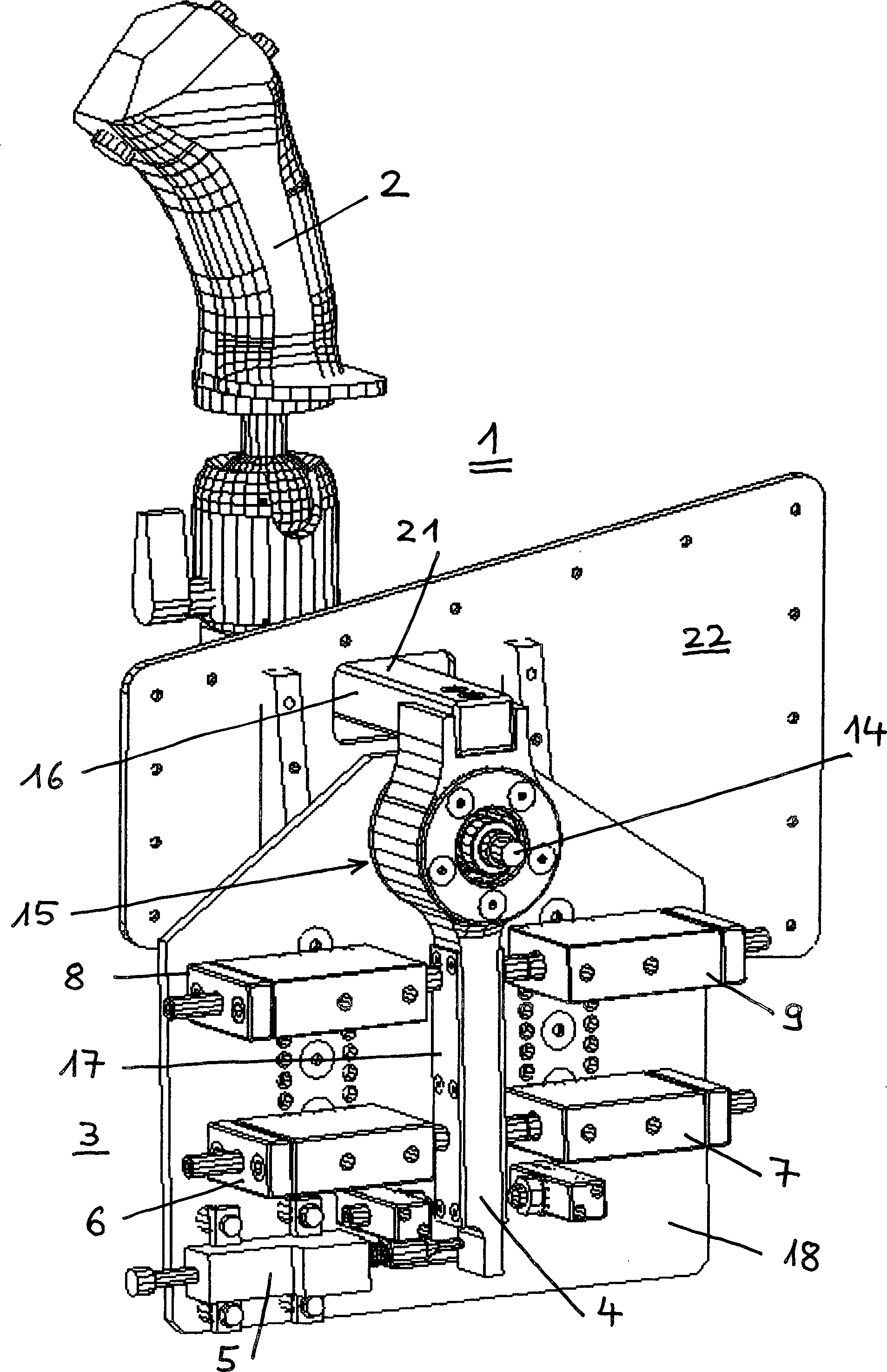
Kraftgesteuerte Schubhebelvorrichtung (1) zur Einstellen des Schubes eines mit Nachbrenner versehenen Triebwerks eines Kampfflugzeugs mit einem Schubhebel (15) mit einem Handgriff (2) zur Betätigung durch den Piloten, wobei der Schubhebel (15) mit einem Signalerzeuger (5) zur Erzeugung eines Steuersignals zum Einstellen des Triebwerksschubs gekoppelt ist, dadurch gekennzeichnet, dass der Schubhebel (15) ein zentral gelagerter zweiarmiger Hebel ist, an dessen erstem Hebelarm (16) der Handgriff (2) befestigt ist und dessen zweiter Hebelarm (17) ein Betätigungselement (4) bildet, welches mit dem Signalerzeuger (5) zusammenwirkt, wobei ein erstes Federpaket mit zwei gegensinnig wirkenden Federelementen (6, 7) vorgesehen ist, welches das Betätigungselement (4) in einer Grundstellung hält und mit einem zweiten Federpaket mit zwei gegensinnig wirkenden Federelementen (8, 9), welches, bezogen auf das erste Federpaket in unterschiedlicher Entfernung zum Schwenklager (14) des Schubhebels (15) angeordnet und so justiert ist, dass die Federelemente (8, 9) erst nach Überwindung einer durch das erste Federpaket bestimmten Schwenkkraft...force controlled Throttle lever device (1) for adjusting the thrust of an afterburner Engine of a fighter plane with a thrust lever (15) with one Handle (2) for actuation by the pilot, wherein the thrust lever (15) with a signal generator (5) for generating a control signal for adjusting the engine thrust is coupled, characterized in that the thrust lever (15) is a centrally mounted two-armed lever, on the first lever arm (16) the handle (2) is fixed and the second lever arm (17) an actuator (4), which cooperates with the signal generator (5), wherein a first spring assembly with two counter-acting spring elements (6, 7) is provided, which the actuating element (4) in one Basic position holds and with a second spring package with two opposing acting Spring elements (8, 9), which, based on the first spring assembly at different distances to the pivot bearing (14) of the push lever (15) is arranged and adjusted so that the spring elements (8, 9) only after overcoming a determined by the first spring package pivoting force ...
Description
Die Erfindung betrifft eine kraftgesteuerte Schubhebelvorrichtung zum Einstellen des Triebwerkschubs eines Kampfflugzeugs gemäß dem Oberbegriff des Anspruchs 1.The The invention relates to a force-controlled thrust lever device for Adjusting the engine thrust of a combat aircraft according to the preamble of claim 1.
In einem Kampfflugzeug wird der Triebwerkschub mit der „Throttle", d.h. mit einem handbetätigten Schubhebel, vom Piloten geregelt. Der normale Regelbereich erstreckt sich von Leerlauf (idle) bis voller Schub (max dry). Zusätzlich kann, sofern ein solcher vorgesehen ist, der Nachbrenner eingeschaltet, geregelt und ausgeschaltet werden (min/max Afterburner). Herkömmlicherweise wird der Schubhebel hierzu auf einer Länge von ca. 150 bis 200 mm verstellt.In A combat aircraft becomes the engine thrust with the "throttle", i.e. with a hand-operated Throttle, regulated by the pilot. The normal control range extends ranging from idle to full thrust (max dry). In addition, if such is provided, the afterburner is switched on, be regulated and turned off (min / max afterburner). traditionally, the thrust lever is adjusted to a length of about 150 to 200 mm for this purpose.
Die Schubhebelvorrichtung sollte verschiedene ergonomische Anforderungen an die Kraft-, Weg- und Bewegungscharakteristik erfüllen, damit der Pilot den Schub schnell und präzise einstellen kann. Bei der Landung beispielsweise müssten sehr feine und genaue Eingaben vorgenommen werden können. Die Schubhebelvorrichtung darf dabei nicht ruckeln. Andererseits sollten unabsichtliche Eingaben vermieden werden, die nötige Kraft zur Verstellung sollte daher nicht zu klein sein. Der Nachbrennerbereich muss deutlich abgetrennt sein, damit er nicht unabsichtlich angewählt wird. Diese Anforderungen haben zur Entwicklung komplexer und teurer elektronischer sog. Force Feedback Throttle Einheiten geführt.The Throttle lever device should have different ergonomic requirements to meet the force, travel and motion characteristics, so that the Pilot the thrust quickly and accurately can adjust. When landing, for example, would have very fine and accurate inputs can be made. The thrust lever device may not stutter. On the other hand, unintentional inputs be avoided, the necessary Power for adjustment should therefore not be too small. The afterburner area must be clearly separated so that it is not dialed unintentionally. These requirements have led to the development of more complex and more expensive electronic so-called Force Feedback Throttle units.
Als bekannt vorausgesetzt wird eine Schubhebelvorrichtung, d.h. ein Schubhebel zum Einstellen des Triebwerkschubs eines Kampfflugzeugs mit einem Handgriff zur Betätigung durch einen Piloten und einer mit dem Handgriff ge koppelten Signalerzeugungseinrichtung zur Erzeugung eines zum Einstellen des Triebwerkschubs verwendeten Steuersignals.When As is known, a push-lever device, i. one Throttle lever for adjusting the engine thrust of a fighter jet with a handle for operation by a pilot and a GE coupled to the handle signal generating device for generating an engine thrust adjustment Control signal.
Derzeit bekannte Schubhebelvorrichtungen dieser Art arbeiten mit einem den Handgriff tragenden und mit der Signalerzeugungseinrichtung gekoppelten Hebel, der nach Art einer rotierenden Bewegung um eine Achse drehbar oder der linear verschiebbar gelagert ist.Currently Known thrust lever devices of this type work with a Handle carrying and coupled to the signal generating device Lever which rotates about an axis in the manner of a rotating movement or is mounted linearly displaceable.
Bei modernen Flugzeugen werden die Triebwerke elektronisch geregelt („by wire"), trotzdem ist die Art der Bedienung beibehalten worden, die noch auf den Erfordernissen älterer Flugzeuge beruht, bei denen die Triebwerke über ein Gestänge geregelt werden (z.B. Mig 29). Die Abtrennung des Nachbrennerbereichs erfolgt herkömmlich über eine Kulisse (seitliche Bewegung des Griffs) oder über eine zusätzliche Kraft, die überwunden werden muss, oder über einen zusätzlich zu betätigenden Hebel. Diese konventionelle Bauweise beinhaltet jedoch einige Nachteile gemessen an den Erfordernissen an ein modernes Kampfflugzeug. Reibung in der Mechanik behindert präzise Eingaben. Geräte mit mechanischen Reibungsbremsen müssen häufig gewartet und eingestellt werden. In einem Trainer-Flugzeug müssen die Schubhebelvorrichtungen gekoppelt sein, so dass sie in der gleichen Stellung stehen. Zusätzlich muss der Instructor die Möglichkeit haben, die Kontrolle vollständig zu übernehmen. Mit einer mechanischen Kopplung der Throttles ist dies nur mit erheblichem Aufwand durch ein Gestänge zwischen dem vorderen und dem hinteren Cockpit zu erreichen.at modern aircraft, the engines are electronically controlled ( "By wire "), anyway The type of operation has been maintained, still on the needs of older aircraft is based, in which the engines are controlled by a linkage (e.g., Mig 29). The separation of the afterburner area is conventionally carried out via a Backdrop (lateral movement of the handle) or over an additional Force that overcome must be, or over an additional to be operated Lever. However, this conventional construction involves some disadvantages measured against the requirements of a modern combat aircraft. friction in mechanics hinders precise Inputs. equipment With mechanical friction brakes must be serviced and adjusted frequently become. In a trainer plane, the thrust lever devices must be coupled so that they are in the same position. In addition, must the instructor the opportunity have the control completely to take over. With a mechanical coupling of the Throttles this is only with substantial Effort through a linkage between the front and rear cockpit.
Aus
der
Der Erfindung liegt die Aufgabe zugrunde, eine gattungsgemäße kraftbetätigte Schubhebelvorrichtung dergestalt zu verbessern, dass sie platzsparend aufgebaut ist und bei geringen Stellwegen die Steuerung der Triebwerksleistung und das Zu-/ und Abschalten des Nachbrenners erlaubt.Of the Invention is based on the object, a generic power-operated thrust lever device to improve so that it is built to save space and at low control ranges, the control of engine performance and the on / off of the afterburner allowed.
Diese Aufgabe wird bei einer gattungsgemäßen kraftbetätigten Schubhebelvorrichtung durch die kennzeichnenden Merkmale des Anspruches 1 gelöst.These Task is in a generic power-operated thrust lever device solved by the characterizing features of claim 1.
Vorteilhafte Ausgestaltungen sind Gegenstand der Unteransprüche 2 bis 12.advantageous Embodiments are the subject of subclaims 2 to 12.
Durch die Erfindung wird eine kraftgesteuerte Schubhebelvorrichtung zum Einstellen des Triebwerkschubs eines Kampfflugzeugs mit einem Handgriff zur Betätigung durch einen Piloten und einer mit dem Handgriff gekoppelten Signalerzeugungseinrichtung zur Erzeugung eines zum Einstellen des Triebwerkschubs verwendeten Steuersignals geschaffen. Erfindungsgemäß ist es vorgesehen, dass die Signalerzeugungseinrichtung zur Erzeugung des Steuersignals in Abhängigkeit von der bei der Betätigung durch den Piloten auf den Handgriff ausgeübten Kraft vorgesehen ist.By The invention is a force-controlled thrust lever device for Adjusting the engine thrust of a fighter plane with a handle for operation by a pilot and a signal generator coupled to the handle for generating an engine thrust adjustment Control signal created. According to the invention, it is provided that the Signal generating device for generating the control signal in dependence from the at the operation provided by the pilot on the handle force exerted.
Die erfindungsgemäße Lösung besteht somit in einer kraftgesteuerten Schubhebelvorrichtung, die sich gegenüber den herkömmlichen, weggesteuerten Schubhebeln kaum noch bewegt. Die Steuerung des Schubs und das Ein-/ Ausschalten des Nachbrenners erfolgt über die Kraft, die auf die Schubhebelvorrichtung ausgeübt wird. Nach vorne drücken erhöht die Triebwerksleistung, nach hinten ziehen reduziert sie. Ein Bewegen des Handgriffes nach vorne, über den ersten Einwirkpunkt des zweiten Federpaketes hinaus, schaltet den Nachbrenner ein und ein Bewegen des Handgriffes nach hinten, über den zweiten Einwirkpunkt des zweiten Federpaketes, schaltet den Nachbrenner aus.The solution according to the invention thus consists in a force-controlled thrust lever device, which is compared with the conventional, path-controlled Thrust levers barely moved. The control of the thrust and the on / off of the afterburner is done via the force exerted on the thrust lever device. Pushing forward increases engine power, pulling backwards reduces it. Moving the handle forward, beyond the first point of action of the second spring assembly, turns on the afterburner, and moving the handle backward over the second point of action of the second spring pack shuts off the afterburner.
Aufgrund der geringen Bewegung kann der Schubhebelvorrichtungsgriff über einen Hebelarm von der Mechanik, also von der mit dem Handgriff gekoppelten Signalerzeugungseinrichtung getrennt sein. Der Schubhebelvorrichtungsgriff kann in der optimalen Höhe (Höhe des Herzens des Piloten) angeordnet werden. Die Schubhebelvorrichtungsmechanik kann getrennt davon in der Cockpit-Seitenwand eingebaut werden. Dies schafft zusätzlichen Raum für Displays und Controls im Cockpit. Aufgrund der geringen Größe könnte die Schubhebelvorrichtung in bestehenden Flugzeugen nachgerüstet werden. Ein besonderer Vorteil ist es, dass die Regelung des Triebwerks sehr präzise durch feine und genaue Eingaben vorgenommen werden kann.by virtue of the little movement, the thrust lever device handle can over a Lever arm of the mechanics, so coupled with the handle Signal generating device to be separated. The thrust lever device handle can be at the optimal height (Height of Heart of the pilot). The throttle lever mechanism can be installed separately in the cockpit sidewall. This creates additional room for Displays and controls in the cockpit. Due to the small size, the Throttle lever device to be retrofitted in existing aircraft. A special advantage is that the control of the engine very precise through fine and accurate inputs can be made.
Im folgenden wird ein Ausführungsbeispiel der erfindungsgemäßen kraftgesteuerten Schubhebelvorrichtung anhand der Zeichnung erläutert.in the The following will be an embodiment of force-controlled according to the invention Thrust lever device explained with reference to the drawing.
Es zeigt:It shows:
In
den
Die
kraftgesteuerte Schubhebelvorrichtung
Die
Signalerzeugungseinrichtung
Die
Schubhebelvorrichtung
Das
Betätigungselement
Die
die Federeinrichtung bildenden Federelemente
Die
Federelemente
Wie
Wie
Das
erste Paar von Federelementen
Weiterhin
erzeugt das zweite Paar von Federelementen
Weiterhin
ist es vorgesehen, dass das erste Paar von Federelementen
Das
Betätigungselement
Insgesamt
ist das Betätigungselement
Der
Signalerzeuger
Wie
bereits weiter oben erläutert
und in
Eine
Vergrößerung des
Betätigungswegs über die
erste definierte Position hinaus, verbunden mit einer entsprechenden Änderung
des von dem Signalerzeuger
Bei
ausgeschaltetem Nachbrenner entspricht eine Bewegung des Betätigungselements
Bei
eingeschaltetem Nachbrenner entspricht eine Bewegung des Betätigungselements
Bei
ausgeschaltetem Nachbrenner entspricht eine Bewegung des Betätigungselements
Bei
eingeschaltetem Nachbrenner entspricht eine Bewegung des Betätigungselements
Durch
die kraftgesteuerte Schubhebelvorrichtung kann ausgehend von einer
kraftfreien Grundstellung des Handgriffs
- 11
- SchubhebelvorrichtungThrust lever device
- 22
- Handgriffhandle
- 33
- SignalerzeugungseinrichtungSignal generator
- 44
- Betätigungselementactuator
- 55
- Signalerzeugersignal generator
- 6, 7, 8, 96 7, 8, 9
- Federelementspring element
- 6a, 7a, 8a, 9a6a, 7a, 8a, 9a
- Spiralfederspiral spring
- 6b, 7b, 8b, 9b6b 7b, 8b, 9b
- Druckstößelpushrod
- 6c, 7c, 8c, 9c6c, 7c, 8c, 9c
- Druckplatteprinting plate
- 6d, 7d, 8d, 9d6d, 7d, 8d, 9d
- GewindestiftSet screw
- 1010
- Gehäuseboxhousing box
- 1313
- Betätigungsstiftactuating pin
- 13a13a
- Federfeather
- 1414
- Drehachseaxis of rotation
- 1515
- Hebellever
- 1616
- erster Hebelarmfirst lever arm
- 1717
- zweiter Hebelarmsecond lever arm
- 1818
- erste Gehäuseplattefirst housing plate
- 1919
- zweite Gehäuseplattesecond housing plate
- 2121
- Kragarmcantilever
- 2222
- VerkleidungsplatteFacing tile
- 2323
- Kugelgelenkball joint
- 23a23a
- Feststellschraubelocking screw
- 2424
- Befestigungsmutterfixing nut
- 2525
- Befestigungsschraubefixing screw
- 2626
- Befestigungsschraubefixing screw
- 2727
- Löcherholes
- 2828
- Justierschraubeadjusting screw
- 3030
- StellsignalerzeugungseinrichtungControl signal generation means
- 4040
- Triebwerkengine
Claims (12)
Priority Applications (4)
| Application Number | Priority Date | Filing Date | Title |
|---|---|---|---|
| DE10338026A DE10338026B4 (en) | 2003-08-19 | 2003-08-19 | Power-operated thrust lever device for adjusting the engine thrust of a combat aircraft |
| EP04018789A EP1508517B1 (en) | 2003-08-19 | 2004-08-07 | Force-controlled power lever for adjusting the thrust of the engine of a combat aircraft |
| DE502004001779T DE502004001779D1 (en) | 2003-08-19 | 2004-08-07 | Power controlled throttle for adjusting the engine thrust of a fighter jet |
| US10/920,452 US7313468B2 (en) | 2003-08-19 | 2004-08-18 | Force-controlled throttle for adjusting the engine thrust of a combat aircraft |
Applications Claiming Priority (1)
| Application Number | Priority Date | Filing Date | Title |
|---|---|---|---|
| DE10338026A DE10338026B4 (en) | 2003-08-19 | 2003-08-19 | Power-operated thrust lever device for adjusting the engine thrust of a combat aircraft |
Publications (2)
| Publication Number | Publication Date |
|---|---|
| DE10338026A1 DE10338026A1 (en) | 2005-03-24 |
| DE10338026B4 true DE10338026B4 (en) | 2006-02-23 |
Family
ID=34042199
Family Applications (2)
| Application Number | Title | Priority Date | Filing Date |
|---|---|---|---|
| DE10338026A Expired - Fee Related DE10338026B4 (en) | 2003-08-19 | 2003-08-19 | Power-operated thrust lever device for adjusting the engine thrust of a combat aircraft |
| DE502004001779T Expired - Lifetime DE502004001779D1 (en) | 2003-08-19 | 2004-08-07 | Power controlled throttle for adjusting the engine thrust of a fighter jet |
Family Applications After (1)
| Application Number | Title | Priority Date | Filing Date |
|---|---|---|---|
| DE502004001779T Expired - Lifetime DE502004001779D1 (en) | 2003-08-19 | 2004-08-07 | Power controlled throttle for adjusting the engine thrust of a fighter jet |
Country Status (3)
| Country | Link |
|---|---|
| US (1) | US7313468B2 (en) |
| EP (1) | EP1508517B1 (en) |
| DE (2) | DE10338026B4 (en) |
Families Citing this family (8)
| Publication number | Priority date | Publication date | Assignee | Title |
|---|---|---|---|---|
| FR2984267B1 (en) * | 2011-12-19 | 2015-08-28 | Airbus Operations Sas | SYSTEM FOR CONTROLLING THE ENERGY OF A VEHICLE |
| CN103640702A (en) * | 2013-11-28 | 2014-03-19 | 江西洪都航空工业集团有限责任公司 | Central control mechanism of aircraft |
| CN105366061A (en) * | 2015-11-17 | 2016-03-02 | 江西洪都航空工业集团有限责任公司 | Electronically-controlled stopping device for rear cabin control engine throttle |
| US9862499B2 (en) | 2016-04-25 | 2018-01-09 | Airbus Operations (S.A.S.) | Human machine interface for displaying information relative to the energy of an aircraft |
| FR3058806B1 (en) | 2016-11-14 | 2019-01-25 | Dassault Aviation | DEVICE FOR MANAGING THE MECHANICAL ENERGY OF AN AIRCRAFT, HAVING A FORCE APPLICATION SYSTEM ON A CONTROL KNOB, AIRCRAFT AND ASSOCIATED METHOD |
| US11479364B2 (en) | 2017-12-13 | 2022-10-25 | Safe Flight Instrument, Llc | Aircraft torque control device |
| US20210371083A1 (en) * | 2018-10-15 | 2021-12-02 | Safe Flight lnstrument Corporation | Aircraft torque control device |
| CN113277067B (en) * | 2021-05-26 | 2022-11-01 | 贵州华阳电工有限公司 | Mechanical structure with speed reducing plate handle capable of adjusting operating force |
Citations (3)
| Publication number | Priority date | Publication date | Assignee | Title |
|---|---|---|---|---|
| US4513235A (en) * | 1982-01-22 | 1985-04-23 | British Aerospace Public Limited Company | Control apparatus |
| US4982918A (en) * | 1988-01-29 | 1991-01-08 | British Aerospace Public Limited Company | Force sensitive aircraft throttle with feedback |
| US5065962A (en) * | 1989-12-27 | 1991-11-19 | Rockwell International Corporation | Digital power controller |
Family Cites Families (7)
| Publication number | Priority date | Publication date | Assignee | Title |
|---|---|---|---|---|
| US4420808A (en) * | 1980-04-01 | 1983-12-13 | United Technologies Corporation | Multi-axis force stick, self-trimmed aircraft flight control system |
| US4477043A (en) * | 1982-12-15 | 1984-10-16 | The United States Of America As Represented By The Secretary Of The Air Force | Biodynamic resistant control stick |
| US4907970A (en) * | 1988-03-30 | 1990-03-13 | Grumman Aerospace Corporation | Sidestick-type thrust control simulator |
| GB9008526D0 (en) * | 1990-04-17 | 1990-10-17 | British Aerospace | Control apparatus |
| US5264768A (en) * | 1992-10-06 | 1993-11-23 | Honeywell, Inc. | Active hand controller feedback loop |
| GB2313176B (en) * | 1996-01-04 | 1998-12-09 | Daimler Benz Ag | Operating-element arrangement useable to control the longitudinal movement of a motor vehicle |
| GB9706447D0 (en) * | 1997-03-27 | 1997-10-15 | British Aerospace | Electronic control apparatus |
-
2003
- 2003-08-19 DE DE10338026A patent/DE10338026B4/en not_active Expired - Fee Related
-
2004
- 2004-08-07 EP EP04018789A patent/EP1508517B1/en not_active Expired - Lifetime
- 2004-08-07 DE DE502004001779T patent/DE502004001779D1/en not_active Expired - Lifetime
- 2004-08-18 US US10/920,452 patent/US7313468B2/en not_active Expired - Fee Related
Patent Citations (3)
| Publication number | Priority date | Publication date | Assignee | Title |
|---|---|---|---|---|
| US4513235A (en) * | 1982-01-22 | 1985-04-23 | British Aerospace Public Limited Company | Control apparatus |
| US4982918A (en) * | 1988-01-29 | 1991-01-08 | British Aerospace Public Limited Company | Force sensitive aircraft throttle with feedback |
| US5065962A (en) * | 1989-12-27 | 1991-11-19 | Rockwell International Corporation | Digital power controller |
Also Published As
| Publication number | Publication date |
|---|---|
| EP1508517A1 (en) | 2005-02-23 |
| DE502004001779D1 (en) | 2006-11-30 |
| US7313468B2 (en) | 2007-12-25 |
| DE10338026A1 (en) | 2005-03-24 |
| US20050085958A1 (en) | 2005-04-21 |
| EP1508517B1 (en) | 2006-10-18 |
Similar Documents
| Publication | Publication Date | Title |
|---|---|---|
| EP3916185B1 (en) | Furniture drive system | |
| DE102019101300A1 (en) | Retractable device for actuating a motor vehicle door with improved ice breakage function | |
| DE102012111315A1 (en) | Pedal system for generating a force curve with hysteresis | |
| EP3973131A1 (en) | Furniture fitting | |
| EP3015081B1 (en) | Surgical instrument with a manual control device | |
| EP0270966A2 (en) | Electronic organ keyboard | |
| DE102004019785B4 (en) | Flap fitting e.g. for furniture flap, positioned between safe in cabinet body locking vertical closing position and open position upward adjustable with setting lever and in operation position axle | |
| DE10338026B4 (en) | Power-operated thrust lever device for adjusting the engine thrust of a combat aircraft | |
| DE102011122445A1 (en) | Reset device for a steering column switch device of a motor vehicle and motor vehicle | |
| EP3263397B1 (en) | Suspension device | |
| EP1258212A2 (en) | Chair, particularly office-chair, with adjustably preloaded backrest | |
| EP2927063B1 (en) | Pedal force simulating device | |
| WO2002033286A1 (en) | Device for releasing a gas spring | |
| EP2501921B1 (en) | Positioning device for converting a rotary motion into a linear motion | |
| DE102010021676B4 (en) | Actuation device for a flight simulator | |
| EP1826080B1 (en) | Actuating device for a vehicle parking brake | |
| DE102006034879B3 (en) | Sliding microtome for cutting object, has levers with guiding sections and guiding surfaces, where sections work together with surfaces such that movement of one lever in two different directions moves another lever in target direction | |
| DE102006050430A1 (en) | Hand-held working tool for use in engine transmission, has driving engine with actuator, and transmission device is transferred on positioning element by movement of actuator | |
| DE102013210892A1 (en) | Front unit of a board binding | |
| DE4417184B4 (en) | Actuator for a valve | |
| DE202014102482U1 (en) | Device for moving a folded flap movably received on a furniture body and furniture with such a device | |
| DE102022108353A1 (en) | Control lever with active handle for haptic feedback | |
| DE1780417A1 (en) | Device for mechanically adjusting a braking force limiter installed in a motor vehicle, which controls the braking force acting on an axle of the motor vehicle | |
| EP2927041B1 (en) | Assembly for a hydraulic actuating device | |
| DE102011122405A1 (en) | Steering column switch device for a motor vehicle and motor vehicle with a steering column switch device |
Legal Events
| Date | Code | Title | Description |
|---|---|---|---|
| OP8 | Request for examination as to paragraph 44 patent law | ||
| 8364 | No opposition during term of opposition | ||
| R081 | Change of applicant/patentee |
Owner name: AIRBUS DEFENCE AND SPACE GMBH, DE Free format text: FORMER OWNER: EADS DEUTSCHLAND GMBH, 85521 OTTOBRUNN, DE Effective date: 20140814 |
|
| R119 | Application deemed withdrawn, or ip right lapsed, due to non-payment of renewal fee |