DE10331932B4 - Turbo molecular pump - Google Patents
Turbo molecular pump Download PDFInfo
- Publication number
- DE10331932B4 DE10331932B4 DE10331932.8A DE10331932A DE10331932B4 DE 10331932 B4 DE10331932 B4 DE 10331932B4 DE 10331932 A DE10331932 A DE 10331932A DE 10331932 B4 DE10331932 B4 DE 10331932B4
- Authority
- DE
- Germany
- Prior art keywords
- spacer rings
- stator
- firm connection
- spacers
- produced
- Prior art date
- Legal status (The legal status is an assumption and is not a legal conclusion. Google has not performed a legal analysis and makes no representation as to the accuracy of the status listed.)
- Expired - Fee Related
Links
Images


Classifications
-
- F—MECHANICAL ENGINEERING; LIGHTING; HEATING; WEAPONS; BLASTING
- F04—POSITIVE - DISPLACEMENT MACHINES FOR LIQUIDS; PUMPS FOR LIQUIDS OR ELASTIC FLUIDS
- F04D—NON-POSITIVE-DISPLACEMENT PUMPS
- F04D29/00—Details, component parts, or accessories
- F04D29/40—Casings; Connections of working fluid
- F04D29/52—Casings; Connections of working fluid for axial pumps
- F04D29/54—Fluid-guiding means, e.g. diffusers
- F04D29/541—Specially adapted for elastic fluid pumps
- F04D29/542—Bladed diffusers
-
- F—MECHANICAL ENGINEERING; LIGHTING; HEATING; WEAPONS; BLASTING
- F04—POSITIVE - DISPLACEMENT MACHINES FOR LIQUIDS; PUMPS FOR LIQUIDS OR ELASTIC FLUIDS
- F04D—NON-POSITIVE-DISPLACEMENT PUMPS
- F04D19/00—Axial-flow pumps
- F04D19/02—Multi-stage pumps
- F04D19/04—Multi-stage pumps specially adapted to the production of a high vacuum, e.g. molecular pumps
- F04D19/042—Turbomolecular vacuum pumps
Landscapes
- Engineering & Computer Science (AREA)
- Mechanical Engineering (AREA)
- General Engineering & Computer Science (AREA)
- Non-Positive Displacement Air Blowers (AREA)
Abstract
Turbomolekularpumpe mit Rotor- (14) und Statorscheiben (16), welche abwechselnd hinter einander angeordnet sind und ihr Zusammenwirken einen Pumpeffekt erzeugt, wobei die Statorscheiben (16) durch Distanzringe (18, 19, 18a, 19a, 18b, 19b, 18c, 19c, 18d, 19d) auf Abstand gehalten werden, die so gestaltet sind, dass sie eine feste Verbindung mit dem jeweiligen Nachbarring eingehen, so dass sie in ihrer Gesamtheit die Fixierung und Zentrierung der Statorscheiben (16) übernehmen; dadurch gekennzeichnet, dass die feste Verbindung zwischen den Distanzringen (18a, 19a) durch Verschraubung über ein Gewinde (20) hergestellt wird; oder dass die feste Verbindung zwischen den Distanzringen (18b, 19b) durch einen Clipverschluss, bestehend aus einem Steg (22) und einer Nut (23) hergestellt wird; oder dass die feste Verbindung zwischen den Distanzringen (18c, 19c) durch Verstiftung (24) in radialer Richtung hergestellt wird; oder dass die feste Verbindung zwischen den Distanzringen (18d, 19d) über eine Passung (26) durch Verpressen kraftschlüssig hergestellt wird.Turbomolecular pump with rotor (14) and stator (16), which are arranged alternately behind each other and their interaction produces a pumping effect, wherein the stator discs (16) by spacer rings (18, 19, 18 a, 19 c , 18d, 19d) are kept at a distance, which are designed so that they form a firm connection with the respective adjacent ring, so that they take over in their entirety the fixing and centering of the stator disks (16); characterized in that the fixed connection between the spacer rings (18a, 19a) is made by screwing over a thread (20); or that the firm connection between the spacer rings (18b, 19b) is made by a clip closure consisting of a web (22) and a groove (23); or that the firm connection between the spacer rings (18c, 19c) is made by pinning (24) in the radial direction; or that the firm connection between the spacer rings (18d, 19d) via a fit (26) is produced by pressing force fit.
Description
Die Erfindung betrifft eine Turbomolekularpumpe gemäß dem Oberbegriff des ersten Anspruchs 1, wie beispielweise aus der
Die aktiven Pumpelemente einer Turbomolekularpumpe bestehen aus mit Schaufeln versehenen Rotor- und Statorscheiben, die abwechselnd hinter einander angeordnet sind. Die Rotor- und Statorscheiben weisen im Allgemeinen jeweils einen inneren Tragring auf, der auf der Außenseite mit den Schaufeln bestückt ist. Die Schaufeln der Rotorscheiben, welche mit hoher Geschwindigkeit umlaufen, ergeben im Zusammenwirken mit den Statorschaufeln den Pumpeffekt. Durch Distanzringe, welche am äußeren Umfang zwischen den Statorscheiben liegen, werden diese so auf Abstand gehalten, dass die Rotorscheiben zwischen ihnen berührungsfrei rotieren können, wie dies der Art nach beispielweise aus den Druckschriften
Eine Turbomolekularpumpe, bei der die Anzahl der Bauteile reduziert ist, indem jeweils eine Statorscheibe, ein Distanzring und ein Teil des Gehäuses einstückig ausgebildet sind, zeigt die
Der Erfindung liegt die Aufgabe zugrunde, eine Turbomolekularpumpe zu entwickeln, bei der die Anzahl der Bauteile gegenüber herkömmlichen Konstruktionen reduziert ist. Bei verminderten Herstellkosten soll eine einfache Montage möglich sein. Die Integration in Anwendungssysteme soll erleichtert und somit ein variabler und anwendungsorientierter Einsatz erreicht werden.The invention has for its object to develop a turbomolecular pump, in which the number of components compared to conventional designs is reduced. With reduced production costs, a simple assembly should be possible. The integration into application systems should be facilitated and thus a variable and application-oriented application should be achieved.
Diese Aufgabe wird durch eine Turbomolekularpumpe mit den Merkmalen des Anspruchs 1 gelöst.This object is achieved by a turbomolecular pump with the features of
Anspruch 2 stellt eine weitere Ausgestaltungsform der Erfindung dar.
Durch die erfindungsgemäße Anordnung wird die Anzahl der Bauteile gegenüber herkömmlichen Konstruktionen reduziert. Bei verminderten Herstellkosten ist eine einfache Montage möglich. Die Distanzringe sind so miteinander verbunden, dass sie die wesentlichen Aufgaben eines Gehäuses, nämlich die Fixierung und Zentrierung der Statorscheiben, erfüllen. Die restliche Funktion des Gehäuses wird von Teilen des auszupumpenden Rezipienten übernommen. Somit wird eine optimale Anpassung von Pumpe und Rezipient erreicht. Dadurch wird es auch möglich, dass die pumpaktiven Bauelemente in unmittelbarer Nähe der evakuierenden Sphäre gebracht werden können. Durch die Tatsache, dass die Distanzringe in ihrer Gesamtheit die Funktion eines Pumpengehäuses übernehmen, wird dieses entbehrlich.The inventive arrangement, the number of components compared to conventional structures is reduced. At reduced production costs, a simple assembly is possible. The spacers are connected to each other so that they fulfill the essential tasks of a housing, namely the fixation and centering of the stator discs. The remaining function of the housing is taken over by parts of the recipient to be pumped out. Thus, an optimal adjustment of pump and recipient is achieved. This also makes it possible that the pump-active components can be brought in the immediate vicinity of the evacuating sphere. Due to the fact that the spacers take over the function of a pump housing in its entirety, this is unnecessary.
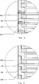
Anhand der
Das Gehäuse
Erfindungsgemäß werden die Distanzringe
In
In
Eine Abdichtung zwischen den einzelnen Distanzringen und zwischen Distanzringen und anderen Bauteilen ist hier nicht dargestellt. Sie kann durch an sich bekannte Anordnungen, wie sie zum Beispiel in der
Claims (2)
Priority Applications (4)
| Application Number | Priority Date | Filing Date | Title |
|---|---|---|---|
| DE10331932.8A DE10331932B4 (en) | 2003-07-15 | 2003-07-15 | Turbo molecular pump |
| JP2004164365A JP2005036798A (en) | 2003-07-15 | 2004-06-02 | Turbo molecular pump |
| EP04014174.9A EP1498612B1 (en) | 2003-07-15 | 2004-06-17 | Turbo molecular pump |
| US10/890,730 US7278822B2 (en) | 2003-07-15 | 2004-07-14 | Turbomolecular pump |
Applications Claiming Priority (1)
| Application Number | Priority Date | Filing Date | Title |
|---|---|---|---|
| DE10331932.8A DE10331932B4 (en) | 2003-07-15 | 2003-07-15 | Turbo molecular pump |
Publications (2)
| Publication Number | Publication Date |
|---|---|
| DE10331932A1 DE10331932A1 (en) | 2005-02-03 |
| DE10331932B4 true DE10331932B4 (en) | 2017-08-24 |
Family
ID=33461927
Family Applications (1)
| Application Number | Title | Priority Date | Filing Date |
|---|---|---|---|
| DE10331932.8A Expired - Fee Related DE10331932B4 (en) | 2003-07-15 | 2003-07-15 | Turbo molecular pump |
Country Status (4)
| Country | Link |
|---|---|
| US (1) | US7278822B2 (en) |
| EP (1) | EP1498612B1 (en) |
| JP (1) | JP2005036798A (en) |
| DE (1) | DE10331932B4 (en) |
Families Citing this family (11)
| Publication number | Priority date | Publication date | Assignee | Title |
|---|---|---|---|---|
| DE102005045283B4 (en) * | 2005-09-22 | 2014-05-15 | Pfeiffer Vacuum Gmbh | Vacuum pumping system |
| DE102006050565A1 (en) * | 2006-10-26 | 2008-04-30 | Pfeiffer Vacuum Gmbh | Stator disk for turbo-molecular pump, has plate at outer ring side, so that plate fulfills spacer ring function, and support ring connected with plate, where plate is turned away from plane, and side is turned outwards in radial direction |
| DE102007048703A1 (en) * | 2007-10-11 | 2009-04-16 | Oerlikon Leybold Vacuum Gmbh | Multi-stage turbomolecular pump pump rotor |
| DE102008004297A1 (en) | 2008-01-15 | 2009-07-16 | Oerlikon Leybold Vacuum Gmbh | Turbo molecular pump |
| US8591204B2 (en) * | 2008-03-31 | 2013-11-26 | Shimadzu Corporation | Turbo-molecular pump |
| ATE513132T1 (en) * | 2008-07-10 | 2011-07-15 | Grundfos Management As | PUMP UNIT |
| DE102008056352A1 (en) * | 2008-11-07 | 2010-05-12 | Oerlikon Leybold Vacuum Gmbh | vacuum pump rotor |
| DE102008058149A1 (en) * | 2008-11-20 | 2010-05-27 | Oerlikon Leybold Vacuum Gmbh | Turbo-molecular pump, has rotor element arranged in pump housing, and stator rings surrounding rotor element, where rings exhibit attachment piece extending in longitudinal direction such that adjacent stator ring is arranged within piece |
| US8221098B2 (en) * | 2009-03-09 | 2012-07-17 | Honeywell International Inc. | Radial turbomolecular pump with electrostatically levitated rotor |
| GB2498816A (en) | 2012-01-27 | 2013-07-31 | Edwards Ltd | Vacuum pump |
| CN114593075B (en) * | 2022-03-15 | 2023-03-24 | 北京中科科仪股份有限公司 | Molecular pump |
Citations (7)
| Publication number | Priority date | Publication date | Assignee | Title |
|---|---|---|---|---|
| DE2523390B1 (en) * | 1975-05-27 | 1976-05-13 | Pfeiffer Vakuumtechnik | STATOR BRACKET FOR TURBO MOLECULAR PUMPS |
| JPH04330397A (en) * | 1991-04-30 | 1992-11-18 | Fujitsu Ltd | Turbo molecular pump |
| DE3722164C2 (en) * | 1987-07-04 | 1995-04-20 | Balzers Pfeiffer Gmbh | Turbomolecular pump |
| DE29717764U1 (en) * | 1997-10-06 | 1997-11-20 | Leybold Vakuum GmbH, 50968 Köln | Stator for a turbomolecular vacuum pump |
| DE19951954A1 (en) * | 1999-10-28 | 2001-05-03 | Pfeiffer Vacuum Gmbh | Turbomolecular pump |
| US20010016160A1 (en) * | 1997-06-27 | 2001-08-23 | Ebara Corporation | Turbo-molecular pump |
| DE10010371A1 (en) * | 2000-03-02 | 2001-09-06 | Pfeiffer Vacuum Gmbh | Turbomolecular pump |
Family Cites Families (10)
| Publication number | Priority date | Publication date | Assignee | Title |
|---|---|---|---|---|
| US1288360A (en) * | 1916-11-06 | 1918-12-17 | Ludwig W Zaar | Turbine. |
| US2610786A (en) * | 1946-06-25 | 1952-09-16 | Gen Electric | Axial flow compressor |
| US3032260A (en) * | 1955-07-12 | 1962-05-01 | Latham Manufactruing Co | Rotary apparatus and method of making the same |
| JPS57212395A (en) * | 1981-06-24 | 1982-12-27 | Hitachi Ltd | Molecular pump |
| DE3402549A1 (en) * | 1984-01-26 | 1985-08-01 | Leybold-Heraeus GmbH, 5000 Köln | Molecular vacuum pump |
| US5052887A (en) * | 1988-02-26 | 1991-10-01 | Novikov Nikolai M | Turbomolecular vacuum pump |
| JPH02131089U (en) * | 1989-03-31 | 1990-10-30 | ||
| JP3469055B2 (en) * | 1997-08-20 | 2003-11-25 | 三菱重工業株式会社 | Turbo molecular pump |
| JP3748323B2 (en) * | 1998-01-09 | 2006-02-22 | 株式会社荏原製作所 | Turbo molecular pump |
| US6503050B2 (en) * | 2000-12-18 | 2003-01-07 | Applied Materials Inc. | Turbo-molecular pump having enhanced pumping capacity |
-
2003
- 2003-07-15 DE DE10331932.8A patent/DE10331932B4/en not_active Expired - Fee Related
-
2004
- 2004-06-02 JP JP2004164365A patent/JP2005036798A/en active Pending
- 2004-06-17 EP EP04014174.9A patent/EP1498612B1/en not_active Expired - Lifetime
- 2004-07-14 US US10/890,730 patent/US7278822B2/en not_active Expired - Fee Related
Patent Citations (7)
| Publication number | Priority date | Publication date | Assignee | Title |
|---|---|---|---|---|
| DE2523390B1 (en) * | 1975-05-27 | 1976-05-13 | Pfeiffer Vakuumtechnik | STATOR BRACKET FOR TURBO MOLECULAR PUMPS |
| DE3722164C2 (en) * | 1987-07-04 | 1995-04-20 | Balzers Pfeiffer Gmbh | Turbomolecular pump |
| JPH04330397A (en) * | 1991-04-30 | 1992-11-18 | Fujitsu Ltd | Turbo molecular pump |
| US20010016160A1 (en) * | 1997-06-27 | 2001-08-23 | Ebara Corporation | Turbo-molecular pump |
| DE29717764U1 (en) * | 1997-10-06 | 1997-11-20 | Leybold Vakuum GmbH, 50968 Köln | Stator for a turbomolecular vacuum pump |
| DE19951954A1 (en) * | 1999-10-28 | 2001-05-03 | Pfeiffer Vacuum Gmbh | Turbomolecular pump |
| DE10010371A1 (en) * | 2000-03-02 | 2001-09-06 | Pfeiffer Vacuum Gmbh | Turbomolecular pump |
Also Published As
| Publication number | Publication date |
|---|---|
| DE10331932A1 (en) | 2005-02-03 |
| EP1498612A2 (en) | 2005-01-19 |
| EP1498612A3 (en) | 2011-09-14 |
| EP1498612B1 (en) | 2015-07-29 |
| US7278822B2 (en) | 2007-10-09 |
| JP2005036798A (en) | 2005-02-10 |
| US20050013710A1 (en) | 2005-01-20 |
Similar Documents
| Publication | Publication Date | Title |
|---|---|---|
| DE10331932B4 (en) | Turbo molecular pump | |
| WO2017041997A1 (en) | Turbo ventilator with heat sink | |
| DE10012181A1 (en) | Centrifugal pump with knobbed impeller and knobbed impeller therefor | |
| DE69104749T2 (en) | Improved turbomolecular pump. | |
| DE2436635B2 (en) | Hydraulic machine | |
| EP2401505B1 (en) | Multi-inlet vacuum pump | |
| DE3722164C2 (en) | Turbomolecular pump | |
| DE102007044945A1 (en) | vacuum pump | |
| EP1130269B1 (en) | Turbo-molecular pump | |
| EP1201928B1 (en) | Disks for a turbo molecular pump | |
| EP1850011B1 (en) | Rotor or stator disc for a molecular pump | |
| EP3500732B1 (en) | Pumping unit | |
| EP1200740A1 (en) | Feed pump | |
| EP2165085B1 (en) | Pump for a household appliance | |
| DE102019215454A1 (en) | Electric machine | |
| EP1187991B1 (en) | Delivery pump | |
| DE102009039119B4 (en) | Vacuum pump and arrangement with vacuum pump | |
| DE102008058149A1 (en) | Turbo-molecular pump, has rotor element arranged in pump housing, and stator rings surrounding rotor element, where rings exhibit attachment piece extending in longitudinal direction such that adjacent stator ring is arranged within piece | |
| EP1101944A2 (en) | Turbo molecular pump | |
| EP2153078B1 (en) | Wet rotor motor | |
| EP3561307B1 (en) | Vacuum pump with an inlet flange and a bearing support in the inlet | |
| DE2046692A1 (en) | Impeller for a turbo molecular pump | |
| DE10304990B4 (en) | Turbo molecular pump | |
| DE60026490T2 (en) | High pressure centrifugal pump | |
| DE102014214049A1 (en) | Turbomachine with centrifugal seal |
Legal Events
| Date | Code | Title | Description |
|---|---|---|---|
| OM8 | Search report available as to paragraph 43 lit. 1 sentence 1 patent law | ||
| 8110 | Request for examination paragraph 44 | ||
| R016 | Response to examination communication | ||
| R018 | Grant decision by examination section/examining division | ||
| R020 | Patent grant now final | ||
| R119 | Application deemed withdrawn, or ip right lapsed, due to non-payment of renewal fee |