DE10325678A1 - Connection system for connecting a stent to a radio-opaque marker and method for establishing a connection between a stent and two or more radio-opaque markers - Google Patents
Connection system for connecting a stent to a radio-opaque marker and method for establishing a connection between a stent and two or more radio-opaque markers Download PDFInfo
- Publication number
- DE10325678A1 DE10325678A1 DE10325678A DE10325678A DE10325678A1 DE 10325678 A1 DE10325678 A1 DE 10325678A1 DE 10325678 A DE10325678 A DE 10325678A DE 10325678 A DE10325678 A DE 10325678A DE 10325678 A1 DE10325678 A1 DE 10325678A1
- Authority
- DE
- Germany
- Prior art keywords
- stent
- clamping
- connection system
- connection
- marker
- Prior art date
- Legal status (The legal status is an assumption and is not a legal conclusion. Google has not performed a legal analysis and makes no representation as to the accuracy of the status listed.)
- Withdrawn
Links
- 239000003550 marker Substances 0.000 title claims abstract description 30
- 238000000034 method Methods 0.000 title description 7
- 239000000463 material Substances 0.000 claims description 17
- 229910045601 alloy Inorganic materials 0.000 claims description 5
- 239000000956 alloy Substances 0.000 claims description 5
- 229910052737 gold Inorganic materials 0.000 claims description 5
- 229910052751 metal Inorganic materials 0.000 claims description 5
- 239000002184 metal Substances 0.000 claims description 5
- 150000002739 metals Chemical class 0.000 claims description 5
- 229910052697 platinum Inorganic materials 0.000 claims description 5
- 229910052735 hafnium Inorganic materials 0.000 claims description 4
- 229910052741 iridium Inorganic materials 0.000 claims description 4
- 229910052750 molybdenum Inorganic materials 0.000 claims description 4
- 229910052758 niobium Inorganic materials 0.000 claims description 4
- 229910052715 tantalum Inorganic materials 0.000 claims description 4
- 229910052721 tungsten Inorganic materials 0.000 claims description 4
- 239000000560 biocompatible material Substances 0.000 claims description 3
- 238000004519 manufacturing process Methods 0.000 claims description 3
- 229910052726 zirconium Inorganic materials 0.000 claims description 3
- 229910000861 Mg alloy Inorganic materials 0.000 claims description 2
- 229910052761 rare earth metal Inorganic materials 0.000 claims 1
- 150000002910 rare earth metals Chemical class 0.000 claims 1
- 238000002513 implantation Methods 0.000 abstract description 4
- 230000006866 deterioration Effects 0.000 abstract description 2
- BASFCYQUMIYNBI-UHFFFAOYSA-N platinum Chemical compound [Pt] BASFCYQUMIYNBI-UHFFFAOYSA-N 0.000 description 5
- 238000010276 construction Methods 0.000 description 4
- 239000010931 gold Substances 0.000 description 4
- KDLHZDBZIXYQEI-UHFFFAOYSA-N Palladium Chemical compound [Pd] KDLHZDBZIXYQEI-UHFFFAOYSA-N 0.000 description 2
- 208000024248 Vascular System injury Diseases 0.000 description 2
- 208000012339 Vascular injury Diseases 0.000 description 2
- 230000015572 biosynthetic process Effects 0.000 description 2
- 230000015556 catabolic process Effects 0.000 description 2
- 238000006731 degradation reaction Methods 0.000 description 2
- 230000007774 longterm Effects 0.000 description 2
- 230000007704 transition Effects 0.000 description 2
- BQCADISMDOOEFD-UHFFFAOYSA-N Silver Chemical compound [Ag] BQCADISMDOOEFD-UHFFFAOYSA-N 0.000 description 1
- 238000006243 chemical reaction Methods 0.000 description 1
- 239000011248 coating agent Substances 0.000 description 1
- 238000000576 coating method Methods 0.000 description 1
- 238000010586 diagram Methods 0.000 description 1
- 238000005516 engineering process Methods 0.000 description 1
- PCHJSUWPFVWCPO-UHFFFAOYSA-N gold Chemical compound [Au] PCHJSUWPFVWCPO-UHFFFAOYSA-N 0.000 description 1
- 239000007943 implant Substances 0.000 description 1
- 229910052747 lanthanoid Inorganic materials 0.000 description 1
- 150000002602 lanthanoids Chemical class 0.000 description 1
- 238000003698 laser cutting Methods 0.000 description 1
- 230000014759 maintenance of location Effects 0.000 description 1
- 229910001092 metal group alloy Inorganic materials 0.000 description 1
- 238000000465 moulding Methods 0.000 description 1
- HLXZNVUGXRDIFK-UHFFFAOYSA-N nickel titanium Chemical compound [Ti].[Ti].[Ti].[Ti].[Ti].[Ti].[Ti].[Ti].[Ti].[Ti].[Ti].[Ni].[Ni].[Ni].[Ni].[Ni].[Ni].[Ni].[Ni].[Ni].[Ni].[Ni].[Ni].[Ni].[Ni] HLXZNVUGXRDIFK-UHFFFAOYSA-N 0.000 description 1
- 229910001000 nickel titanium Inorganic materials 0.000 description 1
- 229910052763 palladium Inorganic materials 0.000 description 1
- 230000002093 peripheral effect Effects 0.000 description 1
- 239000002861 polymer material Substances 0.000 description 1
- 230000000246 remedial effect Effects 0.000 description 1
- 239000000523 sample Substances 0.000 description 1
- 229910052709 silver Inorganic materials 0.000 description 1
- 239000004332 silver Substances 0.000 description 1
- 239000010935 stainless steel Substances 0.000 description 1
- 229910001220 stainless steel Inorganic materials 0.000 description 1
- GUVRBAGPIYLISA-UHFFFAOYSA-N tantalum atom Chemical compound [Ta] GUVRBAGPIYLISA-UHFFFAOYSA-N 0.000 description 1
- 238000011144 upstream manufacturing Methods 0.000 description 1
- 229910052725 zinc Inorganic materials 0.000 description 1
Classifications
-
- A—HUMAN NECESSITIES
- A61—MEDICAL OR VETERINARY SCIENCE; HYGIENE
- A61F—FILTERS IMPLANTABLE INTO BLOOD VESSELS; PROSTHESES; DEVICES PROVIDING PATENCY TO, OR PREVENTING COLLAPSING OF, TUBULAR STRUCTURES OF THE BODY, e.g. STENTS; ORTHOPAEDIC, NURSING OR CONTRACEPTIVE DEVICES; FOMENTATION; TREATMENT OR PROTECTION OF EYES OR EARS; BANDAGES, DRESSINGS OR ABSORBENT PADS; FIRST-AID KITS
- A61F2/00—Filters implantable into blood vessels; Prostheses, i.e. artificial substitutes or replacements for parts of the body; Appliances for connecting them with the body; Devices providing patency to, or preventing collapsing of, tubular structures of the body, e.g. stents
- A61F2/82—Devices providing patency to, or preventing collapsing of, tubular structures of the body, e.g. stents
- A61F2/86—Stents in a form characterised by the wire-like elements; Stents in the form characterised by a net-like or mesh-like structure
- A61F2/90—Stents in a form characterised by the wire-like elements; Stents in the form characterised by a net-like or mesh-like structure characterised by a net-like or mesh-like structure
- A61F2/91—Stents in a form characterised by the wire-like elements; Stents in the form characterised by a net-like or mesh-like structure characterised by a net-like or mesh-like structure made from perforated sheets or tubes, e.g. perforated by laser cuts or etched holes
- A61F2/915—Stents in a form characterised by the wire-like elements; Stents in the form characterised by a net-like or mesh-like structure characterised by a net-like or mesh-like structure made from perforated sheets or tubes, e.g. perforated by laser cuts or etched holes with bands having a meander structure, adjacent bands being connected to each other
-
- A—HUMAN NECESSITIES
- A61—MEDICAL OR VETERINARY SCIENCE; HYGIENE
- A61F—FILTERS IMPLANTABLE INTO BLOOD VESSELS; PROSTHESES; DEVICES PROVIDING PATENCY TO, OR PREVENTING COLLAPSING OF, TUBULAR STRUCTURES OF THE BODY, e.g. STENTS; ORTHOPAEDIC, NURSING OR CONTRACEPTIVE DEVICES; FOMENTATION; TREATMENT OR PROTECTION OF EYES OR EARS; BANDAGES, DRESSINGS OR ABSORBENT PADS; FIRST-AID KITS
- A61F2/00—Filters implantable into blood vessels; Prostheses, i.e. artificial substitutes or replacements for parts of the body; Appliances for connecting them with the body; Devices providing patency to, or preventing collapsing of, tubular structures of the body, e.g. stents
- A61F2/82—Devices providing patency to, or preventing collapsing of, tubular structures of the body, e.g. stents
- A61F2/86—Stents in a form characterised by the wire-like elements; Stents in the form characterised by a net-like or mesh-like structure
- A61F2/90—Stents in a form characterised by the wire-like elements; Stents in the form characterised by a net-like or mesh-like structure characterised by a net-like or mesh-like structure
- A61F2/91—Stents in a form characterised by the wire-like elements; Stents in the form characterised by a net-like or mesh-like structure characterised by a net-like or mesh-like structure made from perforated sheets or tubes, e.g. perforated by laser cuts or etched holes
- A61F2/915—Stents in a form characterised by the wire-like elements; Stents in the form characterised by a net-like or mesh-like structure characterised by a net-like or mesh-like structure made from perforated sheets or tubes, e.g. perforated by laser cuts or etched holes with bands having a meander structure, adjacent bands being connected to each other
- A61F2002/91533—Stents in a form characterised by the wire-like elements; Stents in the form characterised by a net-like or mesh-like structure characterised by a net-like or mesh-like structure made from perforated sheets or tubes, e.g. perforated by laser cuts or etched holes with bands having a meander structure, adjacent bands being connected to each other characterised by the phase between adjacent bands
-
- A—HUMAN NECESSITIES
- A61—MEDICAL OR VETERINARY SCIENCE; HYGIENE
- A61F—FILTERS IMPLANTABLE INTO BLOOD VESSELS; PROSTHESES; DEVICES PROVIDING PATENCY TO, OR PREVENTING COLLAPSING OF, TUBULAR STRUCTURES OF THE BODY, e.g. STENTS; ORTHOPAEDIC, NURSING OR CONTRACEPTIVE DEVICES; FOMENTATION; TREATMENT OR PROTECTION OF EYES OR EARS; BANDAGES, DRESSINGS OR ABSORBENT PADS; FIRST-AID KITS
- A61F2/00—Filters implantable into blood vessels; Prostheses, i.e. artificial substitutes or replacements for parts of the body; Appliances for connecting them with the body; Devices providing patency to, or preventing collapsing of, tubular structures of the body, e.g. stents
- A61F2/82—Devices providing patency to, or preventing collapsing of, tubular structures of the body, e.g. stents
- A61F2/86—Stents in a form characterised by the wire-like elements; Stents in the form characterised by a net-like or mesh-like structure
- A61F2/90—Stents in a form characterised by the wire-like elements; Stents in the form characterised by a net-like or mesh-like structure characterised by a net-like or mesh-like structure
- A61F2/91—Stents in a form characterised by the wire-like elements; Stents in the form characterised by a net-like or mesh-like structure characterised by a net-like or mesh-like structure made from perforated sheets or tubes, e.g. perforated by laser cuts or etched holes
- A61F2/915—Stents in a form characterised by the wire-like elements; Stents in the form characterised by a net-like or mesh-like structure characterised by a net-like or mesh-like structure made from perforated sheets or tubes, e.g. perforated by laser cuts or etched holes with bands having a meander structure, adjacent bands being connected to each other
- A61F2002/9155—Adjacent bands being connected to each other
- A61F2002/91558—Adjacent bands being connected to each other connected peak to peak
-
- A—HUMAN NECESSITIES
- A61—MEDICAL OR VETERINARY SCIENCE; HYGIENE
- A61F—FILTERS IMPLANTABLE INTO BLOOD VESSELS; PROSTHESES; DEVICES PROVIDING PATENCY TO, OR PREVENTING COLLAPSING OF, TUBULAR STRUCTURES OF THE BODY, e.g. STENTS; ORTHOPAEDIC, NURSING OR CONTRACEPTIVE DEVICES; FOMENTATION; TREATMENT OR PROTECTION OF EYES OR EARS; BANDAGES, DRESSINGS OR ABSORBENT PADS; FIRST-AID KITS
- A61F2230/00—Geometry of prostheses classified in groups A61F2/00 - A61F2/26 or A61F2/82 or A61F9/00 or A61F11/00 or subgroups thereof
- A61F2230/0002—Two-dimensional shapes, e.g. cross-sections
- A61F2230/0028—Shapes in the form of latin or greek characters
- A61F2230/0054—V-shaped
-
- A—HUMAN NECESSITIES
- A61—MEDICAL OR VETERINARY SCIENCE; HYGIENE
- A61F—FILTERS IMPLANTABLE INTO BLOOD VESSELS; PROSTHESES; DEVICES PROVIDING PATENCY TO, OR PREVENTING COLLAPSING OF, TUBULAR STRUCTURES OF THE BODY, e.g. STENTS; ORTHOPAEDIC, NURSING OR CONTRACEPTIVE DEVICES; FOMENTATION; TREATMENT OR PROTECTION OF EYES OR EARS; BANDAGES, DRESSINGS OR ABSORBENT PADS; FIRST-AID KITS
- A61F2250/00—Special features of prostheses classified in groups A61F2/00 - A61F2/26 or A61F2/82 or A61F9/00 or A61F11/00 or subgroups thereof
- A61F2250/0058—Additional features; Implant or prostheses properties not otherwise provided for
- A61F2250/0096—Markers and sensors for detecting a position or changes of a position of an implant, e.g. RF sensors, ultrasound markers
- A61F2250/0098—Markers and sensors for detecting a position or changes of a position of an implant, e.g. RF sensors, ultrasound markers radio-opaque, e.g. radio-opaque markers
Landscapes
- Health & Medical Sciences (AREA)
- Engineering & Computer Science (AREA)
- Biomedical Technology (AREA)
- Heart & Thoracic Surgery (AREA)
- Life Sciences & Earth Sciences (AREA)
- Cardiology (AREA)
- Oral & Maxillofacial Surgery (AREA)
- Transplantation (AREA)
- Physics & Mathematics (AREA)
- Vascular Medicine (AREA)
- Optics & Photonics (AREA)
- Animal Behavior & Ethology (AREA)
- General Health & Medical Sciences (AREA)
- Public Health (AREA)
- Veterinary Medicine (AREA)
- Prostheses (AREA)
- Media Introduction/Drainage Providing Device (AREA)
Abstract
Die Erfindung betrifft ein Verbindungssystem zur Verbindung eines Stents mit einem radioopaken Marker. Es ist vorgesehen, ein Verbindungssystem bereitzustellen, dass eine Verbindung des Stents mit einem radioopaken Marker ohne Verschlechterung der mechanischen Eigenschaften des Stents erlaubt und das mit möglichst geringem konstruktivem Aufwand eine für die Sondierung und Implantation des Stents ausreichende Haltekraft bereitstellt. Dies wird dadurch erreicht, dass das Verbindungssystem zumindest eine Spannverbindung (18) aus einem Spannelement (20, 20.1, 20.2, 20.3) und einem Klemmelement (22, 22.1, 22.2, 22.3) umfasst.The The invention relates to a connection system for connecting a stent with a radio-opaque marker. It is intended to provide a connection system that the stent is connected to a radiopaque marker without Deterioration in the mechanical properties of the stent allowed with as much as possible low design effort for probing and implantation of the stent provides sufficient holding force. This will be achieved that the connection system at least one tension connection (18) from a clamping element (20, 20.1, 20.2, 20.3) and a clamping element (22, 22.1, 22.2, 22.3).
Description
Die Erfindung betrifft ein Verbindungssystem zur Verbindung eines Stents mit einem radioopaken Marker sowie ein dazugehöriges Verfahren zur Herstellung einer Verbindung zwischen einem Stent und zwei oder mehrerer radioopaken Markern.The The invention relates to a connection system for connecting a stent with a radio-opaque marker and an associated manufacturing process a connection between a stent and two or more radio-opaque Markers.
Stents, insbesondere für den koronaren Einsatz, werden in der Regel aus Metallen oder Metalllegierungen, z. B. rostfreiem 316L-Stahl oder Nitinol, aber auch speziellen Polymerwerkstoffen geformt. Die eingesetzten Materialien haben allerdings den Nachteil, dass sie gar nicht oder nur schwer radiologisch erfassbar sind. Die Röntgentechnik stellt aber das bei weitem leistungsfähigste Instrument zur Überwachung der Implantation, der relativen Lage und des Expansionszustands des Stents dar.stents especially for coronary inserts, are usually made of metals or metal alloys, z. B. stainless steel 316L or Nitinol, but also special polymer materials shaped. However, the materials used have the disadvantage that they are difficult or impossible to measure radiologically. X-ray technology but it is by far the most powerful surveillance tool the implantation, the relative position and the state of expansion of the stent.
Zur Abhilfe ist es u.a. bekannt den Stent mit radioopaken Materialien zu beschichten. Dazu zählen insbesondere Metalle wie Platin, Palladium, Silber, Gold, Lanthanoide und deren Legierungen. Es hat sich allerdings gezeigt, dass sich eine indifferente Beschichtung über Teile oder gar die gesamte Stentoberfläche negativ auf die mechanischen Eigenschaften des Grundgerüsts des Stents auswirkt. Insbesondere beim Einsatz selbstexpandierender Stents wird eine Expansion im gewünschten Sinne behindert und kann allenfalls durch zusätzliche konstruktive Maßnahmen am Stentdesign kompensiert werden.to Remedial measures include known the stent with radio-opaque materials to coat. These include in particular metals such as platinum, palladium, silver, gold, lanthanoids and their alloys. However, it has been shown that an indifferent coating over Parts or even the entire stent surface negatively affects the mechanical Properties of the basic structure of the stent. Especially when using self-expanding stents will be an expansion in the desired Senses hindered and can at most by additional constructive measures be compensated for in the stent design.
Aus
der
Aufgabe der vorliegenden Erfindung ist es, ein Verbindungssystem bereitzustellen, dass eine Verbindung des Stents mit einem radioopaken Marker ohne Verschlechterung der mechanischen Eigenschaften des Stents erlaubt und das mit möglichst geringem konstruktivem Aufwand eine für die Sondierung und Implantation des Stents ausreichende Haltekraft bereitstellt.task the present invention is to provide a connection system that the stent is connected to a radiopaque marker without Deterioration in the mechanical properties of the stent allowed with as much as possible low design effort for probing and implantation of the stent provides sufficient holding force.
Diese Aufgabe wird durch das Verbindungssystem zur Verbindung eines Stents mit einem radioopaken Marker mit dem Merkmal des Anspruchs 1 gelöst.This Task is through the connection system for connecting a stent solved with a radio-opaque marker with the feature of claim 1.
Der erfindungsgemäße Stent zeichnet sich dadurch aus, dass das Verbindungssystem zumindest eine Spannverbindung aus einem Spannelement und einem Klemmelement umfasst. Es hat sich überraschenderweise gezeigt, dass die an sich einfachen konstruktiven Maßnahmen zu Realisation des erfindungsgemäßen Verbindungssystems sowohl eine zumindest während der Sondierung und Implantation des Stent ausreichende Haltekraft für den Marker zur Verfügung stellen, als auch keine oder nur vernachlässigbar geringe Einflüsse auf die mechanischen Eigenschaften des Stents haben.The stent according to the invention is characterized in that the connection system at least a clamping connection from a clamping element and a clamping element includes. It has turned out surprisingly demonstrated that the simple structural measures to implement the connection system according to the invention both at least during sufficient probing force to probe and implant the stent for the Markers available place, as well as no or only negligible influences have the mechanical properties of the stent.
Das erfindungsgemäße Verbindungssystem hat sich als besonders vorteilhaft beim Einsatz selbstexpandierender Stents erwiesen. Gerade hier müssen die konstruktiven Maßnahmen zur Anbindung eines Markers möglichst geringen oder gar keinen Einfluss auf die Mechanik des Grundgerüst haben. Hierbei muss insbesondere beachtet werden, dass bei Etablierung eines Verbindungssystems möglichst geringe thermische und/oder mechanische Einflüsse auf das Grundgerüst ausgeübt werden, da ansonsten die Eigenschaft des das Grundgerüst bildenden Werkstoffs als Gedächtnismaterial agieren zu können, unerwünscht beeinflusst oder gar verloren gehen kann. Mit Hilfe des erfindungsgemäßen Verbindungssystems kann dies sicher gestellt werden.The has connection system according to the invention proved to be particularly advantageous when using self-expanding Stents proved. Especially here the constructive measures to connect a marker if possible have little or no influence on the mechanics of the basic structure. Here it must be noted in particular that when establishing of a connection system if possible minor thermal and / or mechanical influences are exerted on the basic structure, otherwise the property of the material forming the basic structure as memory material to be able to act undesirable influenced or even lost. With the help of the connection system according to the invention this can be ensured.
Das erfindungsgemäße Verbindungssystem kann auch bei biodegradierbaren Grundgerüsten des Stents, z.B. aus Magnesiumlegierungen, verwendet werden. Die Lage und Form des Verbindungssystems hat dabei keinen oder nur einen geringen Einfluss auf das Degradationsverhalten des Grundgerüstes, so dass ein gleichmäßiger Abbau im lebenden Organismus stattfindet.The Connection system according to the invention can also for biodegradable basic structures of the stent, e.g. made of magnesium alloys, be used. The location and shape of the connection system has little or no influence on the degradation behavior of the basic structure, so that even degradation takes place in the living organism.
Weiterhin ist bevorzugt, dass der Marker selbst als Spann- oder Klemmelement der Spannverbindung ausgebildet ist. Es ist demnach nicht notwendig durch vorgelagerte Bearbeitungsschritte Spann- oder Klemmelemente aus einem anderen Material an den Marker anzuformen.Farther it is preferred that the marker itself as a tensioning or clamping element the clamping connection is formed. It is therefore not necessary through upstream processing steps clamping or clamping elements molded onto the marker from a different material.
In einer weiteren Ausgestaltung des Erfindungsgedankens ist der Marker aus einem biokompatiblen Material geformt, wenn der Marker zum längerfristigen oder dauerhaften Verbleib im Körper des Patienten ausgelegt ist. Gerade bei biodegradierbaren Stents soll auf diese Weise mittel- und langfristigen Komplikationen infolge von Abstoßungsreaktionen des Körpers vorgebeugt werden. Insbesondere ist bevorzugt, wenn der Marker ganz oder in Teilen aus einem oder mehreren Metalle der Gruppe Ta, Nb, Zn, Hf, Mo, W, Au, Pt, Ir, seltene Erden oder deren Legierungen, insbesondere Ptlr, besteht. Die genannten Materialien zeichnen sich durch gute Verfügbarkeit, hohe Biokompatibilität und leichte Verarbeitbarkeit aus.In a further embodiment of the concept of the invention, the marker is formed from a biocompatible material if the marker is designed for long-term or permanent retention in the patient's body. In the case of biodegradable stents in particular, medium and long-term complications due to rejection reactions of the body are to be prevented in this way. It is particularly preferred if the marker consists entirely or in part of one or more metals from the group Ta, Nb, Zn, Hf, Mo, W, Au, Pt, Ir, rare earths or their alloys, in particular Ptlr. The materials mentioned are characterized by good availability, high biocompatibility and easy processing processability.
Ferner ist bevorzugt, dass das Spann- oder Klemmelement der Spannverbindung am Grundgerüst des Stents angeformt ist, d. h. nicht Bestandteil desselben ist. Hierdurch können sehr wirkungsvoll störende Einflüsse des Verbindungssystems auf den Übergang vom nicht-expandierten in den expandierten Zustand des Stents, als auch auf die mechanische Stabilität des Stents im nicht-expandierten und expandierten Zustand minimiert bzw. ausgeschlossen werden.Further it is preferred that the clamping or clamping element of the clamping connection on the basic structure the stent is molded, d. H. is not part of the same. This can very effective disruptive influences of the connection system on the transition from the unexpanded to the expanded state of the stent, as also on the mechanical stability of the stent in the non-expanded and expanded state can be minimized or excluded.
Bevorzugt ist weiterhin, das Spann- oder Klemmelement an beiden (proximalen) Enden des Stents anzuordnen. Hierdurch kann das Herstellungsverfahren vereinfacht werden, da die proximalen Enden des Stents leichter zugänglich sind. Zudem ist es vorteilhaft, das Verbindungssystem derart in das Grundgerüst zu integrieren, dass es nicht oder allenfalls in einem geringem Ausmaß in radialer Erstreckung über die Abmessungen der Umlaufwandung des Grundgerüsts ragt. Somit kann durch die spezielle Lage vermieden werden, dass die Spannverbindung aus der Ebene des Grundgerüsts herausragt und damit bei der Sondierung bzw. Implantation zu Gefäßverletzungen führen könnte.Prefers furthermore, the tensioning or clamping element on both (proximal) Arrange ends of the stent. This allows the manufacturing process be simplified because the proximal ends of the stent are lighter accessible are. It is also advantageous to insert the connection system in this way the basic structure to integrate that it is not, or at most in a little Extent in radial extension over the dimensions of the peripheral wall of the basic structure protrude. Thus through the special location can be avoided that the tension connection the level of the basic framework protrudes and thus during probing or implantation for vascular injuries to lead could.
Ein weiterer Aspekt der Erfindung betrifft ein Verfahren zur Herstellung einer Verbindung zwischen dem Stent und zwei oder mehr radioopaken Markern und zwar unter Verwendung eines Verbindungssystems mit den vorgenannten Merkmalen. Das Verfahren zeichnet sich dadurch aus, dass
- (a) zwei oder mehr Marker über ein Positionierelement miteinander verbunden werden, so dass die Marker mit Ihren Spann- oder Klemmelementen auf die korrespondierenden Spann- oder Klemmelemente des Stents ausgerichtet sind,
- (b) die Marker in einem Arbeitsschritt mit ihren Spann- oder Klemmelementen auf die korrespondierenden Spann- oder Klemmelemente des Stent gesetzt werden und
- (c) anschließend die Verbindung zwischen dem Positionierelement und den Spann- oder Klemmelementen des Markers getrennt wird.
- (a) two or more markers are connected to one another via a positioning element, so that the markers with their tensioning or clamping elements are aligned with the corresponding tensioning or clamping elements of the stent,
- (b) the markers are placed in one work step with their tensioning or clamping elements on the corresponding tensioning or clamping elements of the stent and
- (c) the connection between the positioning element and the tensioning or clamping elements of the marker is then separated.
Durch die vorgenannte Verfahrensdurchführung können in kurzer Zeit mehrere Marker gleichzeitig oder nahezu gleichzeitig mit einem Stent verbunden werden. Durch die besondere Ausgestaltung mittels eines die einzelnen Marker verbindenden Positionierelementes kann eine hohe Positioniergenauigkeit erreicht werden, d. h. die Marker sind für radiologische Untersuchungsmethoden hinreichend genau zentriert und fixiert.By the aforementioned procedure can in a short time several markers simultaneously or almost simultaneously connected to a stent. Due to the special design by means of a positioning element connecting the individual markers high positioning accuracy can be achieved, i. H. the Markers are for radiological examination methods centered with sufficient accuracy and fixed.
Unter dem Begriff "Spannelement" wird eine offene Rahmenkonstruktion verstanden, deren kurzfristige Auslenkung aus einer Ruhelage zur Ausbildung einer Rückstellkraft (Spannkraft) führt.Under the term "clamping element" becomes an open one Understand the frame construction, its short-term deflection a rest position leads to the formation of a restoring force (resilience).
Unter dem Begriff "Klemmelement" wird ein Konstruktionselement verstanden, dass in seiner Formgebung und Abmessungen zur Aufnahme in das Spannelement angepasst ist.Under the term "clamping element" becomes a construction element understood that in its shape and dimensions to accommodate is adapted in the clamping element.
Unter dem Begriff "Spannverbindung" wird eine Verbindung aus einem Spannelement und einem Klemmelement verstanden, bei der das Klemmelement nach Aufnahme in das Spannelement kraftschlüssig in Kontakt mit dem Spannelement gehalten wird.Under the term "tension connection" becomes a connection understood from a clamping element and a clamping element in which the clamping element in a frictional manner after inclusion in the clamping element Contact with the clamping element is kept.
Unter dem Begriff "Grundgerüst" werden alle konstruktiven Teilelemente des Stents verstanden, die beim Übergang vom nicht-expandierten in den expandierten Zustand des Stents mechanischen Belastungen ausgesetzt sind und die im nicht-expandierten und expandierten Zustand zur mechanischen Stabilität des Stents beitragen.Under the term "basic framework" all constructive Understand sub-elements of the stent, which in the transition from the unexpanded mechanical stress in the expanded state of the stent are exposed and in the unexpanded and expanded state for mechanical stability of the stent.
Die Erfindung wird nachfolgend anhand von Ausführungsbeispielen und den dazugehörigen Zeichnungen näher erläutert. Es zeigen:The In the following, the invention is illustrated by means of exemplary embodiments and the associated drawings explained in more detail. It demonstrate:
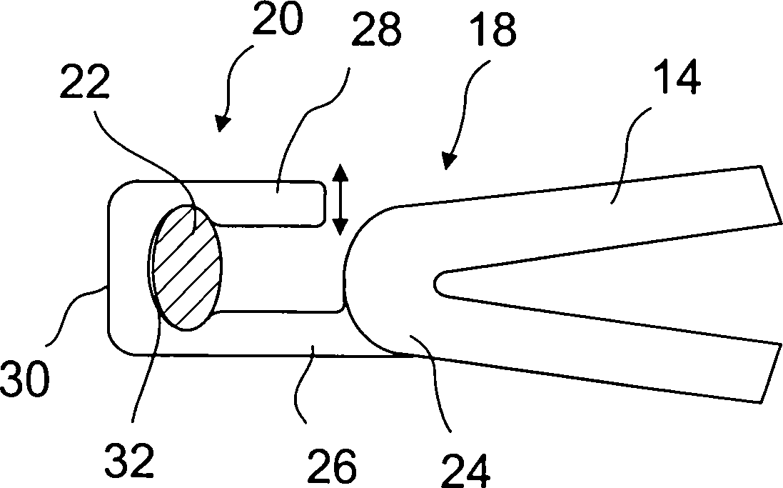
Die
Das
Verbindungssystem
Den
- • Das Material muss aufgrund seiner Verwendung biokompatibel sein.
- • Das Material muss sich zur Realisation einer offenen Rahmenkonstruktion eignen, deren kurze Auslenkung eines Rahmenelementes aus der Ruhelage zur Ausbildung einer Rückstellkraft (Spannkraft) führt, ohne dass die Konstruktion bricht.
- • The material must be biocompatible due to its use.
- • The material must be suitable for the realization of an open frame construction, the short deflection of a frame element from the rest position leads to the formation of a restoring force (clamping force) without the construction breaking.
Denkbar
ist auch, das Spannelement
Wie
in den
Das
klammerförmige
Spannelement
In
den
Die eingesetzten Marker bestehen aus einem biokompatiblen Material. Sie können ganz oder in Teilen aus einem oder mehreren der Metalle der Gruppe Ta, Nb, Zr, Hf, Mo, W, Au, Pt, Ir, seltene Erden oder deren Legierungen, z. B. Ptlr bestehen. Zur besseren radiologischen Unterscheidbarkeit besitzen sie eine in zumindest eine Raumachsrichtung unterscheidbare Form, d. h. sie sind insbesondere nicht kugelsymmetrisch.The Markers used consist of a biocompatible material. You can all or part of one or more of the metals of the group Ta, Nb, Zr, Hf, Mo, W, Au, Pt, Ir, rare earths or their alloys, z. B. Ptlr exist. For better radiological differentiability they have a distinguishable in at least one spatial axis direction Shape, d. H. in particular, they are not spherically symmetrical.
In
den zuvor geschilderten Ausführungsbeispielen
war das Klemmelement
Eine
Verbindung zwischen dem Stent
Sollen
zwei oder mehr radioopake Marker gleichzeitig mit einem Stent verbunden
werden, so kann wie in der
Claims (13)
Priority Applications (6)
| Application Number | Priority Date | Filing Date | Title |
|---|---|---|---|
| DE10325678A DE10325678A1 (en) | 2003-06-02 | 2003-06-02 | Connection system for connecting a stent to a radio-opaque marker and method for establishing a connection between a stent and two or more radio-opaque markers |
| US10/559,592 US20060241741A1 (en) | 2003-06-02 | 2004-06-01 | connecting system for connecting a stent to a radiopaque marker and a process for the production of a connection between a stent and two or more radiopaque markers |
| AT04739485T ATE427719T1 (en) | 2003-06-02 | 2004-06-01 | CONNECTION SYSTEM FOR CONNECTING A STENT TO A RADIOPACK MARKER AND METHOD FOR PRODUCING A CONNECTION BETWEEN A STENT AND TWO OR MORE RADIOPACK MARKERS |
| EP04739485A EP1628594B1 (en) | 2003-06-02 | 2004-06-01 | Connection system for connecting a stent to a radio-opaque marker and method for generation of a connection between a stent and two or more radio-opaque markers |
| DE502004009317T DE502004009317D1 (en) | 2003-06-02 | 2004-06-01 | CONNECTING SYSTEM FOR CONNECTING A STENT TO A RADIOOPAKEN MARKER AND METHOD FOR PRODUCING A CONNECTION BETWEEN ONE STENT AND TWO OR MORE RADIOOPAKEN MARKERS |
| PCT/EP2004/005883 WO2004105642A1 (en) | 2003-06-02 | 2004-06-01 | Connection system for connecting a stent to a radio-opaque marker and method for generation of a connection between a stent and two or more radio-opaque markers |
Applications Claiming Priority (1)
| Application Number | Priority Date | Filing Date | Title |
|---|---|---|---|
| DE10325678A DE10325678A1 (en) | 2003-06-02 | 2003-06-02 | Connection system for connecting a stent to a radio-opaque marker and method for establishing a connection between a stent and two or more radio-opaque markers |
Publications (1)
| Publication Number | Publication Date |
|---|---|
| DE10325678A1 true DE10325678A1 (en) | 2004-12-23 |
Family
ID=33482627
Family Applications (2)
| Application Number | Title | Priority Date | Filing Date |
|---|---|---|---|
| DE10325678A Withdrawn DE10325678A1 (en) | 2003-06-02 | 2003-06-02 | Connection system for connecting a stent to a radio-opaque marker and method for establishing a connection between a stent and two or more radio-opaque markers |
| DE502004009317T Expired - Lifetime DE502004009317D1 (en) | 2003-06-02 | 2004-06-01 | CONNECTING SYSTEM FOR CONNECTING A STENT TO A RADIOOPAKEN MARKER AND METHOD FOR PRODUCING A CONNECTION BETWEEN ONE STENT AND TWO OR MORE RADIOOPAKEN MARKERS |
Family Applications After (1)
| Application Number | Title | Priority Date | Filing Date |
|---|---|---|---|
| DE502004009317T Expired - Lifetime DE502004009317D1 (en) | 2003-06-02 | 2004-06-01 | CONNECTING SYSTEM FOR CONNECTING A STENT TO A RADIOOPAKEN MARKER AND METHOD FOR PRODUCING A CONNECTION BETWEEN ONE STENT AND TWO OR MORE RADIOOPAKEN MARKERS |
Country Status (5)
| Country | Link |
|---|---|
| US (1) | US20060241741A1 (en) |
| EP (1) | EP1628594B1 (en) |
| AT (1) | ATE427719T1 (en) |
| DE (2) | DE10325678A1 (en) |
| WO (1) | WO2004105642A1 (en) |
Cited By (6)
| Publication number | Priority date | Publication date | Assignee | Title |
|---|---|---|---|---|
| DE102006038237A1 (en) * | 2006-08-07 | 2008-02-14 | Biotronik Vi Patent Ag | marker alloy |
| DE102008054845A1 (en) * | 2008-12-18 | 2010-07-01 | Biotronik Vi Patent Ag | Device and method for producing the same |
| DE102012005356A1 (en) * | 2012-03-16 | 2013-09-19 | Admedes Schuessler Gmbh | Body implant with marker element |
| DE102012109736A1 (en) * | 2012-10-12 | 2014-02-06 | Acandis Gmbh & Co. Kg | Medical, intravascularly insertable device e.g. stent, has marker element having a ridge made of second material having higher radiopacity than first material and groove-like recess whose inner contour corresponds to web outer contour |
| US9345819B2 (en) | 2006-08-07 | 2016-05-24 | Biotronik Vi Patent Ag | Marker alloy |
| DE102010025305B4 (en) | 2010-06-28 | 2019-10-02 | Admedes Schuessler Gmbh | Implant for implanting in the human body and method of making the same |
Families Citing this family (30)
| Publication number | Priority date | Publication date | Assignee | Title |
|---|---|---|---|---|
| GB0020491D0 (en) | 2000-08-18 | 2000-10-11 | Angiomed Ag | Stent with attached element and method of making such a stent |
| US20050060025A1 (en) * | 2003-09-12 | 2005-03-17 | Mackiewicz David A. | Radiopaque markers for medical devices |
| EP2169090B3 (en) | 2008-09-30 | 2014-06-25 | Biotronik VI Patent AG | Implant made of a biodegradable magnesium alloy |
| US9468704B2 (en) | 2004-09-07 | 2016-10-18 | Biotronik Vi Patent Ag | Implant made of a biodegradable magnesium alloy |
| KR100511618B1 (en) * | 2005-01-17 | 2005-08-31 | 이경범 | Multi-layer coating of drug release controllable coronary stent and method for manufacturing the same |
| US20070156230A1 (en) | 2006-01-04 | 2007-07-05 | Dugan Stephen R | Stents with radiopaque markers |
| GB0609841D0 (en) | 2006-05-17 | 2006-06-28 | Angiomed Ag | Bend-capable tubular prosthesis |
| GB0609911D0 (en) | 2006-05-18 | 2006-06-28 | Angiomed Ag | Bend-capable stent prosthesis |
| US20130325104A1 (en) | 2006-05-26 | 2013-12-05 | Abbott Cardiovascular Systems Inc. | Stents With Radiopaque Markers |
| DE102006038232A1 (en) * | 2006-08-07 | 2008-02-14 | Biotronik Vi Patent Ag | Endoprosthesis and method for producing such |
| GB0616729D0 (en) * | 2006-08-23 | 2006-10-04 | Angiomed Ag | Method of welding a component to a shape memory alloy workpiece |
| GB0616999D0 (en) * | 2006-08-29 | 2006-10-04 | Angiomed Ag | Annular mesh |
| EP2063824B1 (en) * | 2006-09-07 | 2020-10-28 | Angiomed GmbH & Co. Medizintechnik KG | Helical implant having different ends |
| GB0622465D0 (en) * | 2006-11-10 | 2006-12-20 | Angiomed Ag | Stent |
| GB0624419D0 (en) * | 2006-12-06 | 2007-01-17 | Angiomed Ag | Stenting ring with marker |
| DE102007015670A1 (en) | 2007-03-31 | 2008-10-02 | Biotronik Vi Patent Ag | Stent with radially expandable body |
| GB0706499D0 (en) | 2007-04-03 | 2007-05-09 | Angiomed Ag | Bendable stent |
| GB0717481D0 (en) | 2007-09-07 | 2007-10-17 | Angiomed Ag | Self-expansible stent with radiopaque markers |
| DE102008043642A1 (en) | 2008-11-11 | 2010-05-12 | Biotronik Vi Patent Ag | endoprosthesis |
| US8808353B2 (en) | 2010-01-30 | 2014-08-19 | Abbott Cardiovascular Systems Inc. | Crush recoverable polymer scaffolds having a low crossing profile |
| US8568471B2 (en) | 2010-01-30 | 2013-10-29 | Abbott Cardiovascular Systems Inc. | Crush recoverable polymer scaffolds |
| US8726483B2 (en) | 2011-07-29 | 2014-05-20 | Abbott Cardiovascular Systems Inc. | Methods for uniform crimping and deployment of a polymer scaffold |
| US9233015B2 (en) | 2012-06-15 | 2016-01-12 | Trivascular, Inc. | Endovascular delivery system with an improved radiopaque marker scheme |
| US20140013574A1 (en) * | 2012-07-11 | 2014-01-16 | Intact Vascular, Inc. | Systems and methods for attaching radiopaque markers to a medical device |
| AU2013336672B2 (en) * | 2012-10-25 | 2017-11-23 | Sahajanand Medical Technologies Private Limited | Radiopaque marker for bioresorbable stents |
| CN105163692B (en) * | 2013-02-28 | 2017-09-15 | 波士顿科学国际有限公司 | Implantable medical device that reduces tissue inflammation |
| US9999527B2 (en) | 2015-02-11 | 2018-06-19 | Abbott Cardiovascular Systems Inc. | Scaffolds having radiopaque markers |
| US9700443B2 (en) | 2015-06-12 | 2017-07-11 | Abbott Cardiovascular Systems Inc. | Methods for attaching a radiopaque marker to a scaffold |
| WO2017070147A1 (en) * | 2015-10-23 | 2017-04-27 | Boston Scientific Scimed, Inc. | Radioactive stents |
| US12036138B2 (en) * | 2021-07-30 | 2024-07-16 | Stryker Corporation | Medical stents |
Citations (3)
| Publication number | Priority date | Publication date | Assignee | Title |
|---|---|---|---|---|
| DE19856983A1 (en) * | 1998-06-25 | 1999-12-30 | Biotronik Mess & Therapieg | Implantable, bioresorbable vascular wall support, in particular coronary stent |
| WO2001058384A1 (en) * | 2000-02-14 | 2001-08-16 | Angiomed Gmbh & Co. Medizintechnik Kg | Stent matrix |
| DE10155191A1 (en) * | 2001-11-12 | 2003-05-22 | Dendron Gmbh | Medical implant |
Family Cites Families (9)
| Publication number | Priority date | Publication date | Assignee | Title |
|---|---|---|---|---|
| DE19717475C1 (en) * | 1997-04-25 | 1998-09-03 | Heraeus Gmbh W C | Radially expandable support structure or stent for tubular vessel in body |
| US5741327A (en) * | 1997-05-06 | 1998-04-21 | Global Therapeutics, Inc. | Surgical stent featuring radiopaque markers |
| US6022374A (en) * | 1997-12-16 | 2000-02-08 | Cardiovasc, Inc. | Expandable stent having radiopaque marker and method |
| US6503271B2 (en) * | 1998-01-09 | 2003-01-07 | Cordis Corporation | Intravascular device with improved radiopacity |
| DE59913189D1 (en) * | 1998-06-25 | 2006-05-04 | Biotronik Ag | Implantable, bioabsorbable vessel wall support, in particular coronary stent |
| US7018401B1 (en) * | 1999-02-01 | 2006-03-28 | Board Of Regents, The University Of Texas System | Woven intravascular devices and methods for making the same and apparatus for delivery of the same |
| GB0020491D0 (en) * | 2000-08-18 | 2000-10-11 | Angiomed Ag | Stent with attached element and method of making such a stent |
| US8197535B2 (en) * | 2001-06-19 | 2012-06-12 | Cordis Corporation | Low profile improved radiopacity intraluminal medical device |
| US7235093B2 (en) * | 2003-05-20 | 2007-06-26 | Boston Scientific Scimed, Inc. | Mechanism to improve stent securement |
-
2003
- 2003-06-02 DE DE10325678A patent/DE10325678A1/en not_active Withdrawn
-
2004
- 2004-06-01 EP EP04739485A patent/EP1628594B1/en not_active Expired - Lifetime
- 2004-06-01 WO PCT/EP2004/005883 patent/WO2004105642A1/en not_active Ceased
- 2004-06-01 US US10/559,592 patent/US20060241741A1/en not_active Abandoned
- 2004-06-01 DE DE502004009317T patent/DE502004009317D1/en not_active Expired - Lifetime
- 2004-06-01 AT AT04739485T patent/ATE427719T1/en not_active IP Right Cessation
Patent Citations (3)
| Publication number | Priority date | Publication date | Assignee | Title |
|---|---|---|---|---|
| DE19856983A1 (en) * | 1998-06-25 | 1999-12-30 | Biotronik Mess & Therapieg | Implantable, bioresorbable vascular wall support, in particular coronary stent |
| WO2001058384A1 (en) * | 2000-02-14 | 2001-08-16 | Angiomed Gmbh & Co. Medizintechnik Kg | Stent matrix |
| DE10155191A1 (en) * | 2001-11-12 | 2003-05-22 | Dendron Gmbh | Medical implant |
Cited By (9)
| Publication number | Priority date | Publication date | Assignee | Title |
|---|---|---|---|---|
| DE102006038237A1 (en) * | 2006-08-07 | 2008-02-14 | Biotronik Vi Patent Ag | marker alloy |
| US9345819B2 (en) | 2006-08-07 | 2016-05-24 | Biotronik Vi Patent Ag | Marker alloy |
| DE102008054845A1 (en) * | 2008-12-18 | 2010-07-01 | Biotronik Vi Patent Ag | Device and method for producing the same |
| US8992596B2 (en) | 2008-12-18 | 2015-03-31 | Biotronik Vi Patent Ag | Device and method for producing an endoprosthesis |
| DE102010025305B4 (en) | 2010-06-28 | 2019-10-02 | Admedes Schuessler Gmbh | Implant for implanting in the human body and method of making the same |
| DE102012005356A1 (en) * | 2012-03-16 | 2013-09-19 | Admedes Schuessler Gmbh | Body implant with marker element |
| DE102012005356B4 (en) * | 2012-03-16 | 2016-05-19 | Admedes Schuessler Gmbh | Body implant with marker element and method of making same |
| DE102012109736A1 (en) * | 2012-10-12 | 2014-02-06 | Acandis Gmbh & Co. Kg | Medical, intravascularly insertable device e.g. stent, has marker element having a ridge made of second material having higher radiopacity than first material and groove-like recess whose inner contour corresponds to web outer contour |
| DE102012109736B4 (en) * | 2012-10-12 | 2015-07-16 | Acandis Gmbh & Co. Kg | Medical, intravascular deployable device, delivery system and method of making such device |
Also Published As
| Publication number | Publication date |
|---|---|
| ATE427719T1 (en) | 2009-04-15 |
| US20060241741A1 (en) | 2006-10-26 |
| DE502004009317D1 (en) | 2009-05-20 |
| EP1628594A1 (en) | 2006-03-01 |
| WO2004105642A1 (en) | 2004-12-09 |
| EP1628594B1 (en) | 2009-04-08 |
Similar Documents
| Publication | Publication Date | Title |
|---|---|---|
| EP1628594B1 (en) | Connection system for connecting a stent to a radio-opaque marker and method for generation of a connection between a stent and two or more radio-opaque markers | |
| DE602004009994T2 (en) | Stent with an attached marker in the form of a sleeve | |
| DE69826006T2 (en) | EXPANDABLE STENT WITH VARIABLE THICKNESS | |
| EP1293177B1 (en) | Stent | |
| DE69506683T2 (en) | Coronary arthroplasty and its manufacturing process | |
| DE69332950T2 (en) | BLOOD VESSEL FILTER | |
| DE69809114T2 (en) | Stent for angioplasty | |
| DE69928915T2 (en) | EXPANDABLE UNIT CELL AND INTRALUMINARY STENT | |
| EP2184038B1 (en) | Endoprosthesis | |
| DE69908736T2 (en) | Balloon expandable covered stent | |
| DE69738023T2 (en) | INTRAVASCULAR STENT | |
| DE69831935T2 (en) | BISTABLE SPRING CONSTRUCTION FOR A STENT | |
| EP0847733B1 (en) | Stent | |
| DE69727004T2 (en) | A stent for angioplasty | |
| DE10253633B4 (en) | supporting structure | |
| EP2438891A1 (en) | Stent having increased visibility in the X-ray image | |
| DE19728337A1 (en) | Implantable stent | |
| DE10334868A1 (en) | Implantable device as a replacement organ valve | |
| EP3302373A1 (en) | Stent | |
| DE102004045994A1 (en) | Stent for implantation in or around a hollow organ with marker elements made from a radiopaque material | |
| DE102016110199A1 (en) | Vasospasmusbehandlung | |
| DE102016110410A1 (en) | Stent and manufacturing process | |
| EP1656905B1 (en) | Method for attaching radiopaque markers to a stent | |
| DE102018133345A1 (en) | Stent | |
| DE10317241A1 (en) | stent |
Legal Events
| Date | Code | Title | Description |
|---|---|---|---|
| OM8 | Search report available as to paragraph 43 lit. 1 sentence 1 patent law | ||
| 8139 | Disposal/non-payment of the annual fee |