DE10321350B4 - mixing device - Google Patents
mixing device Download PDFInfo
- Publication number
- DE10321350B4 DE10321350B4 DE10321350A DE10321350A DE10321350B4 DE 10321350 B4 DE10321350 B4 DE 10321350B4 DE 10321350 A DE10321350 A DE 10321350A DE 10321350 A DE10321350 A DE 10321350A DE 10321350 B4 DE10321350 B4 DE 10321350B4
- Authority
- DE
- Germany
- Prior art keywords
- blades
- shaft
- angle
- attack
- diameter
- Prior art date
- Legal status (The legal status is an assumption and is not a legal conclusion. Google has not performed a legal analysis and makes no representation as to the accuracy of the status listed.)
- Expired - Fee Related
Links
Classifications
-
- B—PERFORMING OPERATIONS; TRANSPORTING
- B01—PHYSICAL OR CHEMICAL PROCESSES OR APPARATUS IN GENERAL
- B01F—MIXING, e.g. DISSOLVING, EMULSIFYING OR DISPERSING
- B01F27/00—Mixers with rotary stirring devices in fixed receptacles; Kneaders
- B01F27/60—Mixers with rotary stirring devices in fixed receptacles; Kneaders with stirrers rotating about a horizontal or inclined axis
- B01F27/70—Mixers with rotary stirring devices in fixed receptacles; Kneaders with stirrers rotating about a horizontal or inclined axis with paddles, blades or arms
- B01F27/701—Mixers with rotary stirring devices in fixed receptacles; Kneaders with stirrers rotating about a horizontal or inclined axis with paddles, blades or arms comprising two or more shafts, e.g. in consecutive mixing chambers
- B01F27/702—Mixers with rotary stirring devices in fixed receptacles; Kneaders with stirrers rotating about a horizontal or inclined axis with paddles, blades or arms comprising two or more shafts, e.g. in consecutive mixing chambers with intermeshing paddles
Landscapes
- Chemical & Material Sciences (AREA)
- Chemical Kinetics & Catalysis (AREA)
- Mixers Of The Rotary Stirring Type (AREA)
Abstract
Mischvorrichtung, insbesondere zur Verwendung als kontinuierlich arbeitender Reaktor, bestehend aus mindestens zwei rotierenden Wellen, wobei auf jeder Welle mindestens zwei gegenüberliegende Reihen von Schaufeln angeordnet sind und jede Reihe von Schaufeln aus mindestens zwei einzelnen Schaufeln besteht und dass die Schaufeln in einem Anstellwinkel α zur Längsachse der Welle auf der Welle befestigt sind, dadurch gekennzeichnet, dass die Schaufeln in sich gekrümmt sind, so dass die Schaufeln am Befestigungspunkt an der Welle den Anstellwinkel α und am Außendurchmesser DA den Anstellwinkel Β aufweisen.Mixing device, in particular for use as a continuous reactor, comprising at least two rotating shafts, wherein on each shaft at least two opposite rows of blades are arranged and each row of blades consists of at least two individual blades and that the blades at an angle α to the longitudinal axis the shaft are mounted on the shaft, characterized in that the blades are curved in itself, so that the blades at the attachment point on the shaft have the angle of attack α and the outer diameter D A the angle of attack Β.
Description
Die Erfindung betrifft eine Mischvorrichtung gemöß dem Oberbegriff des Anspruchs 1 sowie ein zugehöriges Mischverfahre gemöß dem Oberbegriff des Anspruchs 5 zur Verwendung als kontinuierlich arbeitender Reaktor.The The invention relates to a mixing device according to the preamble of the claim 1 and an associated Mischverfahre according to the generic term of Claim 5 for use as a continuous reactor.
Diese kontinuierlich arbeitenden Reaktoren werden verwendet zur Aufarbeitung von z. B. Erdöl-Vakuumrückstand, Raffinerie Rückständen, Bitumen oder Kunststoffen, indem sie mit einem heißen körnigen Wärmeträger gemischt und auf die gewünschte Temperatur erhitzt werden.These Continuously operating reactors are used for workup from Z. B. petroleum vacuum residue, Refinery residues, bitumen or plastics, by mixing them with a hot granular heat transfer medium and to the desired temperature to be heated.
Üblicherweise bestehen Mischvorrichtungen dieser Art aus mindestens zwei horizontal ineinandergreifenden Schnecken, die entsprechend den Anforderungen mit unterschiedlicher Länge und Durchmesser gebaut werden. Zur Erzielung bestimmter Eigenschaften, wie die Erhöhung der Umsetzungs- oder Reaktionsgeschwindigkeit oder die Maximierung von Produktausbeute und Produktqualität variiert man die Mischvorrichtung hinsichtlich der Feststoff-Verweilzeit, der Temperatur im Reaktor, oder des Systemdruckes.Usually Mixing devices of this type consist of at least two horizontal interlocking snails, according to the requirements with different length and diameter to be built. To achieve certain properties, like the increase the rate of conversion or reaction or maximization From product yield and product quality, the mixing apparatus is varied in terms of solids residence time, the temperature in the reactor, or the system pressure.
Eine
Vorrichtung, die gleichzeitig als Mischer und thermischer Reaktor
dient, wird beispielsweise in Druckschrift
In
der
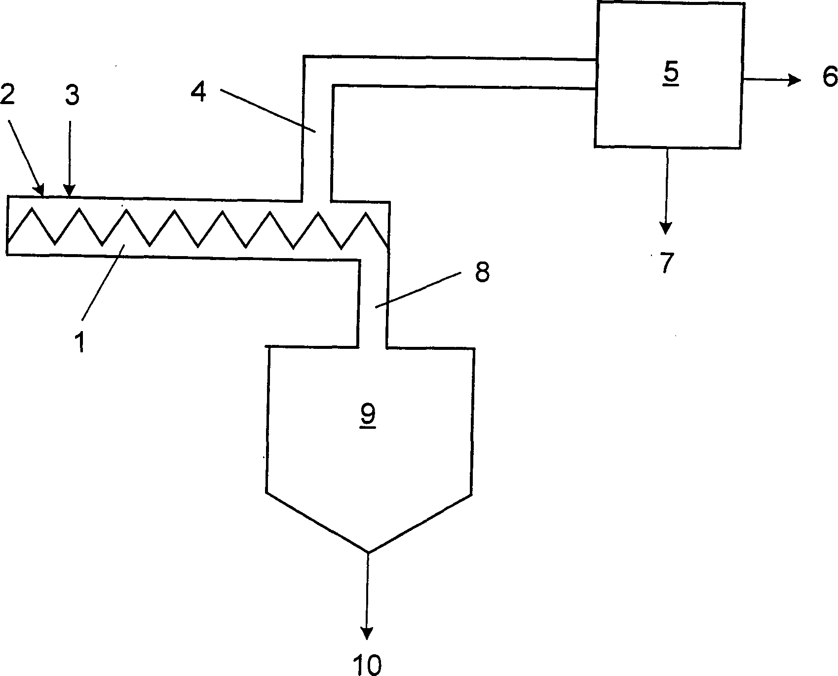
Das kokshaltige Feststoffgemisch, welches das Mischwerk durchlaufen hat und am Austritt angekommen ist, wird zur weiteren Verarbeitung nach unten in einen Pufferbehälter zur Nachentgasung abgezogen.The Coke-containing solid mixture, which pass through the mixer and has arrived at the exit is for further processing down into a buffer tank subtracted for Nachentgasung.
Bei Mischern dieser Bauart wird versucht, eine möglichst gleiche Verweilzeit aller Feststoffpartikel, d. h. Pfropfenströmung zu erreichen. Das heißt, dass die Teilchen, die sich in der Nähe der Welle befinden, mit gleicher axialer Geschwindigkeit transportiert werden, wie die Teilchen, die sich am äußeren Umfang der Schnecke befinden. Gleichzeitig wird versucht, die Verweilzeit so einzustellen, dass der flüssige Einsatzstoff am Ende des Mischers vollständig in Gase, Dämpfe und Koks umgewandelt ist.at Mixers of this type is tried, as far as possible the same residence time all solid particles, d. H. To reach plug flow. It means that the particles that are nearby the shaft are transported at the same axial speed be like the particles that are on the outer circumference of the screw. At the same time an attempt is made to set the residence time so that the liquid Feedstock at the end of the mixer completely in gases, vapors and Coke is converted.
Aufgrund des Geschwindigkeitsprofils zwischen herkömmlichen Wellen und Gehäusewand und der damit verbundenen unerwünschten axialen Durchmischung haben die Partikel in diesen Mischern unterschiedliche Verweilzeiten in der Mischstrecke.by virtue of the velocity profile between conventional waves and housing wall and the associated undesirable axial mixing, the particles have different in these mixers Residence times in the mixing section.
Die Verweilzeit kann durch eine Anpassung der Reaktorlänge, der Wellendrehzahl oder auch der Steigung der Schnecken variiert werden. Um einen möglichst großen Teil der Verweilzeit für die Reaktion zu nutzen, wird versucht, die Einmischzeit zu reduzieren, also die Zeit, die benötigt wird, um Wärmeträger und flüssigen Einsatzstoff vollständig zu vermischen. Idealerweise findet eine vollständig Vermischung bereits bei der Einleitung der Medien am Beginn der Mischstrecke statt. Dies ist aber bisher nicht zu erreichen. Nach dem bekannten Stand der Technik ist die vollständige Vermischung eines flüssigen Einsatzes erst nach dem Durchlaufen der halben Reaktorlänge erfolgt. Um die Verweilzeit zu erhöhen, wäre als Lösung ein längerer Reaktor eine extrem teure Lösung, da die Wellen und Schnecken aus hoch-warmfestem Stahl bestehen und einen Außendurchmesser von 0,8 bis 3 m sowie eine Länge von 6 bis 15 m haben.The Residence time can be adjusted by adjusting the reactor length, the Shaft speed or the pitch of the screw can be varied. To one as possible huge Part of the residence time for to use the reaction, an attempt is made to reduce the mixing time, So the time it takes is to heat transfer and liquid Feedstock completely to mix. Ideally, complete mixing already occurs the introduction of the media at the beginning of the mixing section instead. This but so far can not be achieved. According to the known state of Technique is the complete one Mixing a liquid insert takes place after passing through half the reactor length. To the residence time to increase would be a solution longer Reactor an extremely expensive solution, because the waves and snails are made of high-heat-resistant steel and an outer diameter from 0.8 to 3 m as well as a length from 6 to 15 m.
Zur Beeinflussung der mittleren Verweilzeit und der Verweilzeitverteilung kann die Steigung und die geometrische Anordnung der Mischwendeln variiert werden. Die Geschwindigkeit des Feststoffes im Mischer ist abhängig von der Steigung und der Form der Mischwendel. Mit zunehmender Steigung der Mischwendel nimmt ganz allgemein die axiale Geschwindigkeit der Feststoffpartikel ab und die Verweilzeit zu.to Influencing the average residence time and the residence time distribution can the slope and the geometric arrangement of the mixing spirals be varied. The velocity of the solid in the mixer depends on from the pitch and the shape of the helix. With increasing slope the mixing helix generally takes the axial velocity the solid particles from and the residence time to.
Ausgehend von diesem Stand der Technik liegt der Erfindung die Aufgabe zugrunde, die bisherige Mischvorrichtung derart zu verbessern, dass bei vorgegebener Reaktorlänge die Verweilzeit vergrößert wird und dass das zu verarbeitende Material unabhängig von seiner radialen Entfernung von der Drehachse mit möglichst gleicher Geschwindigkeit transportiert wird.outgoing From this prior art, the invention is based on the object to improve the previous mixing device such that at given reactor length the residence time is increased and that the material to be processed is independent of its radial distance from the axis of rotation with as possible same speed is transported.
Zur Lösung dieser Aufgabe wird die in Anspruch 1 gekennzeichnete Mischvorrichtung vorgeschlagen sowie das Verfahren, das die in Anspruch 5 angegeben Merkmale aufweist. Vorteilhafte Ausgestaltungen sind Gegenstand der Unteransprüche.to solution This object is the characterized in claim 1 mixing device proposed as well as the method that specified in claim 5 Features. Advantageous embodiments are the subject the dependent claims.
Erfindungsgemäß sind bei der eingangs genannten Mischvorrichtung auf jeder Welle mindestens zwei gegenüberliegende Reihen von Schaufeln angeordnet und jede Reihe von Schaufeln besteht aus 2 bis 20 einzelnen Schaufeln. Die Schaufeln sind in einem Anstellwinkel α zur Längsachse der Welle auf der Welle befestigt wobei die Schaufeln in sich gekrümmt sind, so dass die Schaufeln am Befestigungspunkt an der Welle den Anstellwinkel α und am Außendurchmesser den Anstellwinkel β aufweisen. Dadurch, dass statt einer durchgehenden Schnecke eine Reihe von einzelnen Schaufeln verwendet werden, wird eine besonders effiziente Vermischung erreicht. Durch eine Krümmung der Schaufeln, wodurch sich mit zunehmendem Durchmesser ein unterschiedlicher Anstellwinkel zur Längsachse der Welle ergibt, kann die axiale Geschwindigkeit der zu mischenden Teilchen über den gesamten Reaktorquerschnitt vergleichmäßigt werden.According to the invention are at the above-mentioned mixing device on each shaft at least two opposite ones Rows of blades arranged and each row of blades consists of 2 to 20 individual blades. The blades are at an angle α to the longitudinal axis the shaft mounted on the shaft with the blades curved in, so that the blades at the attachment point on the shaft the angle of attack α and the outer diameter have the angle of attack β. Thereby, that instead of a continuous snail a number of individual Shovels are used, a particularly efficient mixing reached. By a curvature of the blades, which varies with increasing diameter Angle of attack to the longitudinal axis As the shaft yields, the axial velocity of the shaft can be mixed Particles over the entire reactor cross-section be made uniform.
Dadurch dass der Anstellwinkel β am Außendurchmesser DA der Schaufeln kleiner gehalten wird als der bisher übliche Wert von ca. 2 · α, wird die axiale Strömungsgeschwindigkeit gleichmäßiger und nähert sich im Idealfall einer Pfropfströmung. Dadurch ergibt sich eine engere Verweilzeitverteilung.As a result of the fact that the angle of attack β at the outer diameter D A of the blades is kept smaller than the hitherto customary value of approximately 2 · α, the axial flow velocity becomes more uniform and, in the ideal case, approaches a plug flow. This results in a narrower residence time distribution.
Nimmt der Anstellwinkel der Schaufeln vom Fußpunkt auf der Welle DW bis zum Außendurchmesser DA kontinuierlich ab, reduziert sich die axiale Geschwindigkeit der zu mischenden Teilchen am Außendurchmesser DA im Verhältnis zur axialen Geschwindigkeit am Durchmesser DW der Welle. Unter der Voraussetzung, dass der Außendurchmesser DA doppelt so groß ist wie der Durchmesser DW (DA = 2 DW), wird über den gesamten Reaktorquerschnitt die gleiche axiale Geschwindigkeit erreicht, wenn der Anstellwinkel β am Außendurchmesser DA halb so groß ist, wie der Anstellwinkel α am Durchmesser DW der Welle. Durch eine vielfache Unterbrechung der Wendel erhöht sich die Scherwirkung beim Transport des Feststoffes durch den Mischer. Die Mischintensität wird gesteigert und damit erfolgt die vollständige Vermischung nicht erst bei der halben Reaktorlänge, sondern bereits deutlich früher. Bei gleicher Reaktorlänge wird eine größere Verweilzeit für die chemische Reaktion erreicht, wodurch bei neuen Anlagen die Reaktorlänge entweder verkleinert oder alternativ die Reaktionszeit erhöht und damit die Reaktionstemperatur gesenkt werden kann.If the angle of attack of the blades decreases continuously from the base point on the shaft D W to the outer diameter D A , the axial velocity of the particles to be mixed at the outer diameter D A decreases in relation to the axial velocity at the diameter D W of the shaft. Assuming that the outer diameter D A is twice as large as the diameter D W (D A = 2 D W ), the same axial velocity is achieved over the entire reactor cross-section, if the angle of attack β at the outer diameter D A is half as large , as the angle of attack α at the diameter D W of the shaft. By a multiple interruption of the coil increases the shear effect during transport of the solid through the mixer. The mixing intensity is increased and thus the complete mixing does not take place until half the reactor length, but already much earlier. With the same reactor length, a longer residence time for the chemical reaction is achieved, whereby in new plants, the reactor length either reduced or alternatively increases the reaction time and thus the reaction temperature can be lowered.
Ausgestaltungsmöglichkeiten der Mischwellen werden mit Hilfe der Zeichnungen beispielhaft erläutert.design options the mixing shafts are exemplified with the aid of the drawings.
Dabei zeigtthere shows
In
das Mischwerk (
In
Dies
wird in
Mit DW = 1.0 m und einer konstanten Drehzahl von 20 Umdrehungen pro Minute beträgt die Umfangsgeschwindigkeit der Teilchen am Befestigungspunkt der Schaufeln VW = 1,05 m/s. Dies ist damit auch die radiale Geschwindigkeit VWr = 1,05 m/s. Bei einem Anstellwinkel α = 16° der Schaufel am Befestigungspunkt an der Welle ergibt sich eine axiale Geschwindigkeit der Teilchen von VWa = 0,3 m/s.With D W = 1.0 m and a constant speed of 20 revolutions per minute, the peripheral speed of the particles at the attachment point of the blades V W = 1.05 m / s. This is also the radial velocity V Wr = 1.05 m / s. At an angle of attack α = 16 ° of the blade at the attachment point on the shaft results in an axial velocity of the particles of V Wa = 0.3 m / s.
Mit DA = 2,0 m und gleicher Drehzahl von 20 Umdrehungen pro Minute beträgt die Umfangsgeschwindigkeit der Teilchen am Außendurchmesser der Schaufeln VA = 2,09 m/s. Dies ist damit auch die radiale Geschwindigkeit VAr = 2,09 m/s. Bei einem Anstellwinkel β = 8° der Schaufel am Außendurchmesser DA der Welle ergibt sich die gleiche axiale Geschwindigkeit der Teilchen von VAa = 0,3 m/s. Selbstverständlich lässt sich die gleiche axiale Geschwindigkeit der Teilchen über den Querschnitt des Mischwerkes auch bei anderen Durchmesserverhältnissen und anderen Anstellwinkeln realisieren.With D A = 2.0 m and the same speed of 20 revolutions per minute, the peripheral speed of the particles at the outer diameter of the blades V A = 2.09 m / s. This is also the radial velocity V Ar = 2.09 m / s. At an angle β = 8 ° of the blade on the outer diameter D A of the shaft results in the same axial velocity of the particles of V Aa = 0.3 m / s. Of course, the same axial velocity of the particles over the cross section of the mixing plant can be realized even with other diameter ratios and other angles of attack.
Claims (5)
Priority Applications (11)
| Application Number | Priority Date | Filing Date | Title |
|---|---|---|---|
| DE10321350A DE10321350B4 (en) | 2003-05-13 | 2003-05-13 | mixing device |
| ES04725681T ES2281792T3 (en) | 2003-05-13 | 2004-04-05 | MIXING DEVICE AND MIXING PROCEDURE USING THIS DEVICE. |
| AT04725681T ATE352369T1 (en) | 2003-05-13 | 2004-04-05 | MIXING APPARATUS AND MIXING METHOD USING SUCH APPARATUS |
| JP2006529674A JP4708348B2 (en) | 2003-05-13 | 2004-04-05 | Mixing equipment |
| MXPA05012173A MXPA05012173A (en) | 2003-05-13 | 2004-04-05 | Mixing device. |
| AU2004238009A AU2004238009B2 (en) | 2003-05-13 | 2004-04-05 | Mixing device |
| PCT/EP2004/003578 WO2004101126A1 (en) | 2003-05-13 | 2004-04-05 | Mixing device |
| DE502004002777T DE502004002777D1 (en) | 2003-05-13 | 2004-04-05 | Mixing device and mixing method using this device |
| US10/556,648 US7677788B2 (en) | 2003-05-13 | 2004-04-05 | Curved blade mixing device |
| CA002529581A CA2529581C (en) | 2003-05-13 | 2004-04-05 | Mixing device |
| EP04725681A EP1622706B1 (en) | 2003-05-13 | 2004-04-05 | Mixing device, and mixing method using that device |
Applications Claiming Priority (1)
| Application Number | Priority Date | Filing Date | Title |
|---|---|---|---|
| DE10321350A DE10321350B4 (en) | 2003-05-13 | 2003-05-13 | mixing device |
Publications (2)
| Publication Number | Publication Date |
|---|---|
| DE10321350A1 DE10321350A1 (en) | 2005-01-13 |
| DE10321350B4 true DE10321350B4 (en) | 2005-04-21 |
Family
ID=33440750
Family Applications (2)
| Application Number | Title | Priority Date | Filing Date |
|---|---|---|---|
| DE10321350A Expired - Fee Related DE10321350B4 (en) | 2003-05-13 | 2003-05-13 | mixing device |
| DE502004002777T Expired - Lifetime DE502004002777D1 (en) | 2003-05-13 | 2004-04-05 | Mixing device and mixing method using this device |
Family Applications After (1)
| Application Number | Title | Priority Date | Filing Date |
|---|---|---|---|
| DE502004002777T Expired - Lifetime DE502004002777D1 (en) | 2003-05-13 | 2004-04-05 | Mixing device and mixing method using this device |
Country Status (10)
| Country | Link |
|---|---|
| US (1) | US7677788B2 (en) |
| EP (1) | EP1622706B1 (en) |
| JP (1) | JP4708348B2 (en) |
| AT (1) | ATE352369T1 (en) |
| AU (1) | AU2004238009B2 (en) |
| CA (1) | CA2529581C (en) |
| DE (2) | DE10321350B4 (en) |
| ES (1) | ES2281792T3 (en) |
| MX (1) | MXPA05012173A (en) |
| WO (1) | WO2004101126A1 (en) |
Families Citing this family (16)
| Publication number | Priority date | Publication date | Assignee | Title |
|---|---|---|---|---|
| ATE488205T1 (en) | 2003-03-14 | 2010-12-15 | Depuy Spine Inc | HYDRAULIC DEVICE FOR BONE CEMENT INJECTION IN PERCUTANEOUS VERTEBROPLASTY |
| US8066713B2 (en) | 2003-03-31 | 2011-11-29 | Depuy Spine, Inc. | Remotely-activated vertebroplasty injection device |
| DE10321350B4 (en) * | 2003-05-13 | 2005-04-21 | Lurgi Ag | mixing device |
| US8415407B2 (en) | 2004-03-21 | 2013-04-09 | Depuy Spine, Inc. | Methods, materials, and apparatus for treating bone and other tissue |
| WO2005030034A2 (en) | 2003-09-26 | 2005-04-07 | Depuy Spine, Inc. | Device for delivering viscous material |
| EP1786343B1 (en) | 2004-07-30 | 2012-05-02 | Depuy Spine, Inc. | Apparatus for treating bone and other tissue |
| US9381024B2 (en) | 2005-07-31 | 2016-07-05 | DePuy Synthes Products, Inc. | Marked tools |
| US9918767B2 (en) | 2005-08-01 | 2018-03-20 | DePuy Synthes Products, Inc. | Temperature control system |
| US8360629B2 (en) | 2005-11-22 | 2013-01-29 | Depuy Spine, Inc. | Mixing apparatus having central and planetary mixing elements |
| US9642932B2 (en) | 2006-09-14 | 2017-05-09 | DePuy Synthes Products, Inc. | Bone cement and methods of use thereof |
| WO2008047371A2 (en) | 2006-10-19 | 2008-04-24 | Depuy Spine, Inc. | Fluid delivery system |
| GB0808739D0 (en) | 2008-05-14 | 2008-06-18 | Univ Aston | Thermal treatment of biomass |
| US9073019B2 (en) * | 2010-04-19 | 2015-07-07 | Cheese & Whey Systems, Inc. | Blade arrangement for a food processing vat |
| US20190002324A1 (en) * | 2016-03-01 | 2019-01-03 | Wh Systems | Method and Apparatus for the Treatment of Waste from Sewage Digestor |
| US10605143B2 (en) | 2017-07-14 | 2020-03-31 | Ford Global Technologies, Llc | Exhaust gas mixer |
| PL248422B1 (en) * | 2023-05-15 | 2025-12-08 | Prorys Spolka Z Ograniczona Odpowiedzialnoscia | Flow-through mixer of peat materials |
Citations (5)
| Publication number | Priority date | Publication date | Assignee | Title |
|---|---|---|---|---|
| DE1118959B (en) * | 1955-07-12 | 1961-12-07 | Draiswerke Ges Mit Beschraenkt | Method and device for the preparation of thermoplastics or thermosets |
| US3090606A (en) * | 1959-09-11 | 1963-05-21 | Strong Scott Mfg Company | Rotary mixing device |
| DE19724074A1 (en) * | 1997-06-07 | 1998-12-10 | Metallgesellschaft Ag | Process for high-temperature short-term distillation of residual oils |
| DE19817518A1 (en) * | 1997-05-09 | 1999-10-14 | Georg Gebhard | Production of storage mineral components |
| DE19959587A1 (en) * | 1999-12-10 | 2001-06-13 | Metallgesellschaft Ag | Process for gentle short-term distillation of residual oils |
Family Cites Families (27)
| Publication number | Priority date | Publication date | Assignee | Title |
|---|---|---|---|---|
| DE29394C (en) * | B. WEIBEZAHL in Magdeburg | Mixing machine for powdery materials | ||
| US43227A (en) * | 1864-06-21 | Improvement in churns | ||
| US1590021A (en) * | 1921-12-02 | 1926-06-22 | Stevens Aylsworth Company | Mixing machine |
| US2017116A (en) * | 1932-04-02 | 1935-10-15 | Harold D Bonnell | Agitating apparatus |
| DE1255098B (en) * | 1962-04-17 | 1967-11-30 | Inst Chemii Ogolnej | Device for the thermal isomerization or disproportionation of alkali salts of benzene carboxylic acids |
| DE1189368B (en) * | 1963-04-24 | 1965-03-18 | Richard Frisse Maschinenfabrik | Conching machine for chocolate masses or the like. |
| US3734469A (en) * | 1970-12-31 | 1973-05-22 | Exxon Research Engineering Co | Reactor vessel and up-down mixer |
| DE3009471C2 (en) * | 1979-03-15 | 1982-04-29 | Tokyo Shibaura Denki K.K., Kawasaki, Kanagawa | Developer transport device for electrostatic copiers |
| US4364667A (en) * | 1981-02-06 | 1982-12-21 | Reiner Ralph | Mixing and transport conveyor |
| US4627735A (en) * | 1985-02-07 | 1986-12-09 | Standard Oil Company (Indiana) | Double reverse helix agitator |
| DE3543745A1 (en) * | 1985-12-11 | 1987-06-19 | Bhs Bayerische Berg | DOUBLE SHAFT MIXER FOR CONTINUOUS AND DISCONTINUOUS OPERATION |
| JPS63151341A (en) * | 1986-12-16 | 1988-06-23 | Obara Yasunori | Dual-screw mixing feed apparatus |
| EP0397894A1 (en) * | 1989-05-13 | 1990-11-22 | Ulrich Krause | Method for continuously bringing together solid powdery or granular materials, and device for carrying out the method |
| US5431860A (en) | 1991-02-01 | 1995-07-11 | Richter Gedeon Vegyeszeti Gyar Rt. | Complex mixing device for dispersion of gases in liquid |
| CH682619A5 (en) * | 1991-06-18 | 1993-10-29 | Buehler Ag | Method and apparatus for producing a shaped product nodules. |
| DE4339628C2 (en) * | 1993-11-20 | 2003-04-10 | Ismar Maschinen Gmbh | kneading |
| DE4401596A1 (en) * | 1994-01-20 | 1995-07-27 | Ekato Ruehr Mischtechnik | Stirrer |
| US5519470A (en) * | 1994-03-04 | 1996-05-21 | Xerox Corporation | Cross mixing paddle wheel |
| US5791779A (en) * | 1996-07-09 | 1998-08-11 | Sandmold Systems, Inc. | Mixing assembly for continuous mixer |
| DE19706364C2 (en) * | 1997-02-19 | 1999-06-17 | Loedige Maschbau Gmbh Geb | Mixing tool |
| JPH1158369A (en) * | 1997-08-22 | 1999-03-02 | Kobe Steel Ltd | Twin-screw continuous kneader |
| US6735530B1 (en) | 1998-09-23 | 2004-05-11 | Sarnoff Corporation | Computational protein probing to identify binding sites |
| JP2000246731A (en) * | 1999-03-02 | 2000-09-12 | Kobe Steel Ltd | Kneading rotor and kneading machine employing this |
| JP2003019425A (en) * | 2001-07-09 | 2003-01-21 | Tookemi:Kk | Remover for adhesion matter on filter sand |
| JP2003205229A (en) * | 2002-01-16 | 2003-07-22 | Aidekku Kk | Stirring method and apparatus |
| DE10321350B4 (en) * | 2003-05-13 | 2005-04-21 | Lurgi Ag | mixing device |
| FR2858250B1 (en) * | 2003-07-30 | 2005-09-09 | Syndicat Intercommunal Pour La | MIXER DEVICE FOR DIVIDED SOLID WASTE |
-
2003
- 2003-05-13 DE DE10321350A patent/DE10321350B4/en not_active Expired - Fee Related
-
2004
- 2004-04-05 US US10/556,648 patent/US7677788B2/en not_active Expired - Fee Related
- 2004-04-05 JP JP2006529674A patent/JP4708348B2/en not_active Expired - Fee Related
- 2004-04-05 DE DE502004002777T patent/DE502004002777D1/en not_active Expired - Lifetime
- 2004-04-05 ES ES04725681T patent/ES2281792T3/en not_active Expired - Lifetime
- 2004-04-05 EP EP04725681A patent/EP1622706B1/en not_active Expired - Lifetime
- 2004-04-05 WO PCT/EP2004/003578 patent/WO2004101126A1/en not_active Ceased
- 2004-04-05 MX MXPA05012173A patent/MXPA05012173A/en active IP Right Grant
- 2004-04-05 CA CA002529581A patent/CA2529581C/en not_active Expired - Fee Related
- 2004-04-05 AU AU2004238009A patent/AU2004238009B2/en not_active Ceased
- 2004-04-05 AT AT04725681T patent/ATE352369T1/en active
Patent Citations (5)
| Publication number | Priority date | Publication date | Assignee | Title |
|---|---|---|---|---|
| DE1118959B (en) * | 1955-07-12 | 1961-12-07 | Draiswerke Ges Mit Beschraenkt | Method and device for the preparation of thermoplastics or thermosets |
| US3090606A (en) * | 1959-09-11 | 1963-05-21 | Strong Scott Mfg Company | Rotary mixing device |
| DE19817518A1 (en) * | 1997-05-09 | 1999-10-14 | Georg Gebhard | Production of storage mineral components |
| DE19724074A1 (en) * | 1997-06-07 | 1998-12-10 | Metallgesellschaft Ag | Process for high-temperature short-term distillation of residual oils |
| DE19959587A1 (en) * | 1999-12-10 | 2001-06-13 | Metallgesellschaft Ag | Process for gentle short-term distillation of residual oils |
Also Published As
| Publication number | Publication date |
|---|---|
| JP4708348B2 (en) | 2011-06-22 |
| CA2529581C (en) | 2009-11-24 |
| ATE352369T1 (en) | 2007-02-15 |
| AU2004238009B2 (en) | 2009-11-12 |
| US20060181959A1 (en) | 2006-08-17 |
| DE502004002777D1 (en) | 2007-03-15 |
| JP2007502207A (en) | 2007-02-08 |
| DE10321350A1 (en) | 2005-01-13 |
| US7677788B2 (en) | 2010-03-16 |
| AU2004238009A1 (en) | 2004-11-25 |
| EP1622706B1 (en) | 2007-01-24 |
| ES2281792T3 (en) | 2007-10-01 |
| EP1622706A1 (en) | 2006-02-08 |
| MXPA05012173A (en) | 2006-08-18 |
| WO2004101126A1 (en) | 2004-11-25 |
| CA2529581A1 (en) | 2004-11-25 |
Similar Documents
| Publication | Publication Date | Title |
|---|---|---|
| DE10321350B4 (en) | mixing device | |
| DE3743051A1 (en) | DEVICE FOR TREATING HIGH VISCOSITY SUBSTANCES | |
| AT511780B1 (en) | PIPE REACTOR FOR THE THERMAL TREATMENT OF BIOMASS | |
| EP3318311B1 (en) | Thin film treatment device | |
| EP0719582A2 (en) | Reactor for free-flowing and higher-viscosity substances | |
| DE60000698T2 (en) | Device and method for ejecting a liquid | |
| EP1631371A1 (en) | Device for the treatment of solid substances | |
| EP3103538A1 (en) | Thin-film vaporiser | |
| DE1959139C3 (en) | Device for the continuous production of polymers with a high degree of polymerization | |
| WO2015074929A1 (en) | Device for producing polymers | |
| EP0019244B1 (en) | Apparatus and process for pyrolyzing waste products | |
| DE2237767A1 (en) | PLANT FOR THE CONTINUOUS MANUFACTURE OF BEER WORT | |
| DE102012103749A1 (en) | Reactor comprises heatable housing, whose upper region has heating surface and is transversed through rotor, where wiper elements are provided for distribution of liquid product on heating surface which has collection and discharge area | |
| EP1841524B1 (en) | Reactor for the continuous and simultaneous production of different polyester products having adjustable variable viscosity, the progress of the process being regulated via the hydraulic drive system/s | |
| DE3332053C2 (en) | ||
| DE2705556C3 (en) | Polymerization reactor | |
| DE1495665A1 (en) | Method and device for the continuous throughput of melts through a reaction device in the production of polycondensation products | |
| EP1285586B1 (en) | Process and apparatus for continuous feeding of confectionery masses | |
| DE10310327A1 (en) | Vertical mixing vessel with rotary agitator, for solids, high viscosity materials, powders, bulk materials and granules, includes stirrer blades curved in plane transverse to drive shaft | |
| CH689444A5 (en) | Reactor for thermal processing of viscous materials, esp. thermoplastic elastomers | |
| EP2488289B1 (en) | Method and use for refining | |
| WO2024068818A1 (en) | Pyrolysis reactor and method for the thermochemical treatment of carbon-containing waste | |
| DE1926987A1 (en) | Polycondensation device | |
| DE1457285A1 (en) | Mixing device for the preparation of dough-like masses | |
| DE1937268C3 (en) | Method and device for the production of chocolate |
Legal Events
| Date | Code | Title | Description |
|---|---|---|---|
| OP8 | Request for examination as to paragraph 44 patent law | ||
| 8364 | No opposition during term of opposition | ||
| 8327 | Change in the person/name/address of the patent owner |
Owner name: LURGI LENTJES AG, 40549 DUESSELDORF, DE |
|
| R119 | Application deemed withdrawn, or ip right lapsed, due to non-payment of renewal fee |