DE10304736B3 - Arrangement for moving a rod or tube within a virtual reality simulator for minimally invasive surgery has a mounting frame assembly and a simulator assembly with a rod or tube that is moved in a simulation manner - Google Patents
Arrangement for moving a rod or tube within a virtual reality simulator for minimally invasive surgery has a mounting frame assembly and a simulator assembly with a rod or tube that is moved in a simulation manner Download PDFInfo
- Publication number
- DE10304736B3 DE10304736B3 DE2003104736 DE10304736A DE10304736B3 DE 10304736 B3 DE10304736 B3 DE 10304736B3 DE 2003104736 DE2003104736 DE 2003104736 DE 10304736 A DE10304736 A DE 10304736A DE 10304736 B3 DE10304736 B3 DE 10304736B3
- Authority
- DE
- Germany
- Prior art keywords
- tube
- rod
- frame
- axis
- motor
- Prior art date
- Legal status (The legal status is an assumption and is not a legal conclusion. Google has not performed a legal analysis and makes no representation as to the accuracy of the status listed.)
- Expired - Fee Related
Links
Classifications
-
- G—PHYSICS
- G06—COMPUTING OR CALCULATING; COUNTING
- G06F—ELECTRIC DIGITAL DATA PROCESSING
- G06F3/00—Input arrangements for transferring data to be processed into a form capable of being handled by the computer; Output arrangements for transferring data from processing unit to output unit, e.g. interface arrangements
- G06F3/01—Input arrangements or combined input and output arrangements for interaction between user and computer
- G06F3/016—Input arrangements with force or tactile feedback as computer generated output to the user
-
- G—PHYSICS
- G06—COMPUTING OR CALCULATING; COUNTING
- G06F—ELECTRIC DIGITAL DATA PROCESSING
- G06F3/00—Input arrangements for transferring data to be processed into a form capable of being handled by the computer; Output arrangements for transferring data from processing unit to output unit, e.g. interface arrangements
- G06F3/01—Input arrangements or combined input and output arrangements for interaction between user and computer
- G06F3/03—Arrangements for converting the position or the displacement of a member into a coded form
- G06F3/033—Pointing devices displaced or positioned by the user, e.g. mice, trackballs, pens or joysticks; Accessories therefor
- G06F3/0346—Pointing devices displaced or positioned by the user, e.g. mice, trackballs, pens or joysticks; Accessories therefor with detection of the device orientation or free movement in a 3D space, e.g. 3D mice, 6-DOF [six degrees of freedom] pointers using gyroscopes, accelerometers or tilt-sensors
-
- G—PHYSICS
- G09—EDUCATION; CRYPTOGRAPHY; DISPLAY; ADVERTISING; SEALS
- G09B—EDUCATIONAL OR DEMONSTRATION APPLIANCES; APPLIANCES FOR TEACHING, OR COMMUNICATING WITH, THE BLIND, DEAF OR MUTE; MODELS; PLANETARIA; GLOBES; MAPS; DIAGRAMS
- G09B23/00—Models for scientific, medical, or mathematical purposes, e.g. full-sized devices for demonstration purposes
- G09B23/28—Models for scientific, medical, or mathematical purposes, e.g. full-sized devices for demonstration purposes for medicine
-
- A—HUMAN NECESSITIES
- A61—MEDICAL OR VETERINARY SCIENCE; HYGIENE
- A61B—DIAGNOSIS; SURGERY; IDENTIFICATION
- A61B17/00—Surgical instruments, devices or methods
- A61B2017/00681—Aspects not otherwise provided for
- A61B2017/00707—Dummies, phantoms; Devices simulating patient or parts of patient
Landscapes
- Engineering & Computer Science (AREA)
- General Engineering & Computer Science (AREA)
- Theoretical Computer Science (AREA)
- Physics & Mathematics (AREA)
- General Physics & Mathematics (AREA)
- Human Computer Interaction (AREA)
- Medicinal Chemistry (AREA)
- Mathematical Analysis (AREA)
- General Health & Medical Sciences (AREA)
- Medical Informatics (AREA)
- Health & Medical Sciences (AREA)
- Algebra (AREA)
- Computational Mathematics (AREA)
- Chemical & Material Sciences (AREA)
- Mathematical Optimization (AREA)
- Mathematical Physics (AREA)
- Pure & Applied Mathematics (AREA)
- Business, Economics & Management (AREA)
- Educational Administration (AREA)
- Educational Technology (AREA)
- Toys (AREA)
Abstract
Es wird eine Einrichtung für die Bewegung eines Stabes/Rohres innerhalb eines/r konstruktiv vorgegebenen Doppelkegel/-Doppelpyramide vorgestellt. Der Stab hat vier Freiheitsgrade der Bewegung, nämlich zwei Schwenkebenen, eine axiale Bewegung und Drehen um die Achse. Motorantriebe treiben oder hemmen die jeweilige Bewegung mit einstellbarem Moment. Der Rahmen für die Antriebe ist in eine Fläche eingebaut, die mindestens drei Ankerpunkte hat, an diesen setzt je eine ausziehbare Gelenkwelle über federelastische Mittel an, die mit ihrem anderen Ende ortsfest und starr verankert ist. Dadurch kann die Fläche über diese Gelenkwellen entweder in eine beliebige Richtung ausgestellt oder einer solchen von außen aufgedrängten Ausstellung entgegengewirkt werden.A device for the movement of a rod / tube within a constructively predetermined double cone / double pyramid is presented. The rod has four degrees of freedom of movement, namely two swivel planes, an axial movement and rotation about the axis. Motor drives drive or inhibit the respective movement with an adjustable torque. The frame for the drives is built into a surface that has at least three anchor points, each with an extendable cardan shaft via spring-elastic means, which is fixed at its other end and rigidly anchored. As a result, the surface can either be exhibited in any direction via these cardan shafts or counteracted such an exhibition imposed from the outside.
Description
Die Erfindung betrifft eine Einrichtung
für die Bewegung
eines Stabes/Rohres innerhalb eines/r durch die Konstruktion der
Einrichtung vorgegebenen Doppelkegels/-Doppelpyramide unter Wahrung einer
unbeweglichen Stelle, dem Invarianten Punkt, auf der Stab-/Rohrachse gemäß Oberbegrift
des Anspruch 1. Eine der artige Einrichtung ist aus der
In Virtual-Reality-Simulatoren, VRS, für die minimalinvasive Chirurgie, MIC, werden Ein-, Ausgabegeräte gebraucht, die einerseits die gängigen endoskopischen Instrumente und das Operationsumfeld nachahmen, gleichzeitig aber in der Lage sind, präzise Positionsdaten für das Simulationsprogramm bereitzustellen und dem Übenden über Kraftrückkopplungssysteme den Tastsinn und das Fühlen von Kräften und Bewegungen zu vermitteln – auch als taktiles Handhaben bezeichnet.In virtual reality simulators, VRS, for the minimally invasive Surgery, MIC, input and output devices are needed, on the one hand the usual Imitate endoscopic instruments and the operating environment, simultaneously but are able to be precise Position data for to provide the simulation program and the sense of touch for the practitioner via force feedback systems and feeling of forces and convey movements - too referred to as tactile handling.
Es gibt auf dem Markt Haptik-IO-Systeme von
der US-Firma „Immersion", die mit Force-Feedback
arbeiten und speziell für
MIC-Simulationssysteme
entwickelt worden sind. Aufgrund der Marktführerschaft dieser Firma stellen
ihre Geräte
den aktuellen Stand der Technik dar. Das System wird unter dem Namen „Laparoscopic
Impuls Engine" vertrieben
und ist beispielsweise in der
Ein Schnittstellengerät mit einer riemengetriebenen Kraftrückkopplung und vier verankerten Aktuatoren wird in der WO 03/009096 A1 beschrieben. Diese Einrichtung vermittelt realistische Eindrücke durch taktile Rückkopplung an den Handhaber. Die Einrichtung schließt ein Übungsinstrument und einen mechanischen Simulationsapparat ein, der an das Übungsinstrument gekoppelt ist. Eine Schnittstelleneinrichtung ist an den Simulationsapparat und ein Rechner an die Schnittstelleneinrichtung gekoppelt, um ein Anwendungsprogramm für die Riemenbewegung einzurichten.An interface device with a belt-driven force feedback and four anchored actuators is described in WO 03/009096 A1. This facility provides realistic impressions through tactile feedback to the handler. The facility includes an exercise instrument and a mechanical one Simulator, which is coupled to the exercise instrument. An interface device is connected to the simulation apparatus and Computer coupled to the interface device to an application program for the Belt movement.
In der
In der
In der
Unter realen Operationsbedingungen befindet sich der Drehpunkt für das Instrument, der Invariante Punkt, im Trokar direkt in oder unmittelbar an der aufgeblasenen Bauchdecke. Im Simulator dagegen befindet sich dieser Drehpunkt konstruktionsbedingt tief unter der virtuellen Bauchdecke. Das vermittelt dem Übenden ein falsches Feeling, das eigentlich nicht antrainiert werden sollte.Under real operating conditions is the fulcrum for the instrument, the invariant point, in the trocar directly in or immediately on the inflated abdominal wall. In the simulator, however, is this fulcrum, due to the design, deep below the virtual one Abdominal wall. That conveys to the practitioner a wrong feeling that shouldn't be trained.
Vom Stande der Technik her liegt
somit eine Einrichtung für
die Bewegung eines Stabes/Rohres innerhalb eines/r durch die Konstruktion
vorgegebenen Doppelkegels/-Doppelpyramide unter Wahrung einer unbeweglichen
Stelle, dem Invarianten Punkt, auf der Stab/Rohrachse vor. Dabei
hat der/das Stab/Rohr hat vier Freiheitsgrade der Bewegung, nämlich:
Schwenken
der Stab-/Rohrachse in zwei zueinander nichtparallelen Ebenen, wobei
der Invariante Punkt auf der Schnittgeraden der beiden Ebenen liegt;
axiales
Bewegen des Stabes/Rohres und Drehen des Stabes/Rohres um sein Achse.From the state of the art there is therefore a device for the movement of a rod / tube within a double cone / double pyramid predetermined by the construction while maintaining an immovable point, the invariante point, on the rod / tube axis. The rod / tube has four degrees of freedom of movement, namely:
Swiveling the rod / tube axis in two planes not parallel to each other, the invariant point lying on the intersection line of the two planes;
axially moving the rod / tube and rotating the rod / tube about its axis.
Zum Bedienen der Freiheitsgrade sind Motorantriebe vorhanden. Diese sind in einem Rahmen aufgehängt, durch den der/das Stab/Rohr ragt. Der/das Stab/Rohr wird dabei entweder über diese Motorantriebe mit vorgegebenem Moment bewegt oder eine dem Stab/Rohr von außen aufgezwungene Bewegung wird über diese Motorantriebe mit vorgegebenem Moment, gehemmt.To operate the degrees of freedom Motor drives available. These are hung in a frame by which the rod / tube protrudes. The rod / tube is either driven by these motors moved with a given moment or a movement imposed on the rod / tube from the outside is about these motor drives with a given torque, inhibited.
Unter realen Operationsbedingungen bewegt sich die aufgeblähte Bauchdecke mit, wenn das Instrument bewegt wird. Diese Bewegungen kann das Gerät nicht simulieren.Under real operating conditions moves the bloated Abdominal wall when the instrument is moved. These movements can the device do not simulate.
Aus diesen mit der Realität nicht übereinstimmenden Eigenschaften ergab sich die Aufgabe, die der Erfindung zugrunde liegt, nämlich einen solchen Virtual-Reality-Simulator bereit zu stellen, mit dem die tatsächlichen Operationsbewegungen getreu simuliert und damit, der Wirklichkeit nahekommend, trainiert werden können.Out of those that do not match reality Properties emerged from the task underlying the invention lies, namely to provide such a virtual reality simulator with which the actual Operation movements faithfully simulated and thus, reality approaching, can be trained.
Die Aufgabe wird durch die kennzeichnenden Merkmale des Anspruchs 1 gelöst. Der Rahmen ist hierzu in eine Fläche eingebaut, die mindestens drei Ankerpunkte hat. An diesen Ankerpunkten setzt je eine über einen Linearantrieb ausziehbare Gelenkwelle über federelastische Mittel an, die mit ihrem andern Ende ortsfest und starr verankert ist. Durch diese Maßnahme kann die Fläche über diese Gelenkwellen entweder in eine beliebige Richtung ausgestellt oder einer solchen von außen aufgedrängten Ausstellung entgegengewirkt werden.The task is characterized by the Features of claim 1 solved. For this purpose, the frame is in one surface installed, which has at least three anchor points. At these anchor points puts one over each a linear drive extendable cardan shaft via spring-elastic means which is fixed and rigidly anchored at its other end. By this measure can the area over this Cardan shafts either issued in any direction or such from the outside counteracted crowded exhibition become.
Mit dem prinzipiellen Aufbau dieser Einrichtungen kann das durch den Durchbruch der Trägerplatte ragende Rohr positionsbestimmt gehalten und geführt werden. Genauer: eine von außen auf das Rohr einwirkende Führung kann über einstellbare Motormomente gehemmt und damit taktiles Führen simuliert werden, oder das Rohr wird über die Motorantriebe bewegt, das wäre dann die Roboterfunktion.With the basic structure of this This can be done by opening the carrier plate protruding pipe are held and guided in a position-specific manner. More precisely: one of Outside guide acting on the pipe can about adjustable motor torques inhibited and thus simulating tactile guiding or the pipe will be over the motor drives are moving, that would be then the robot function.
In den jeweils auf den Anspruch 1
bezogenen Unteransprüchen
2 bis 4 werden verschieden Realisierungen zur motorgehemmten oder
motorgetriebenen Bewegung des Rohres beschrieben:
In Anspruch
2 ist beschrieben, dass der Rahmen ein Kreisring ist, dessen innere
Mantelfläche
eine Kugelsegmentfläche
ist, in der eine Kugel formschlüssig gleitet,
durch die hindurch der/das Stab/Rohr polar ragt. Drei Kugel- oder
Walzenantriebe sitzen auf der Fläche
oder der Stirnseite des Rahmens und drücken an die Kugel an. Die Achsen
der drei Antriebe liegen in einer Ebene durch die Kugel und bilden
ein gleichseitiges Dreieck. Mit einem solchen Aufbau kann das Rohr
schon in jede Richtung des Bewegungsdoppelkegels oder der -pyramide
geschwenkt werden. Für die
Drehung des Rohres sitzt im Innern der Kugel ein Rotorantrieb und
für die
axiale Bewegung des Rohres ist darin ein Linearantrieb verankert.In the respective subclaims 2 to 4, which relate to claim 1, different implementations for motor-inhibited or motor-driven movement of the pipe are described:
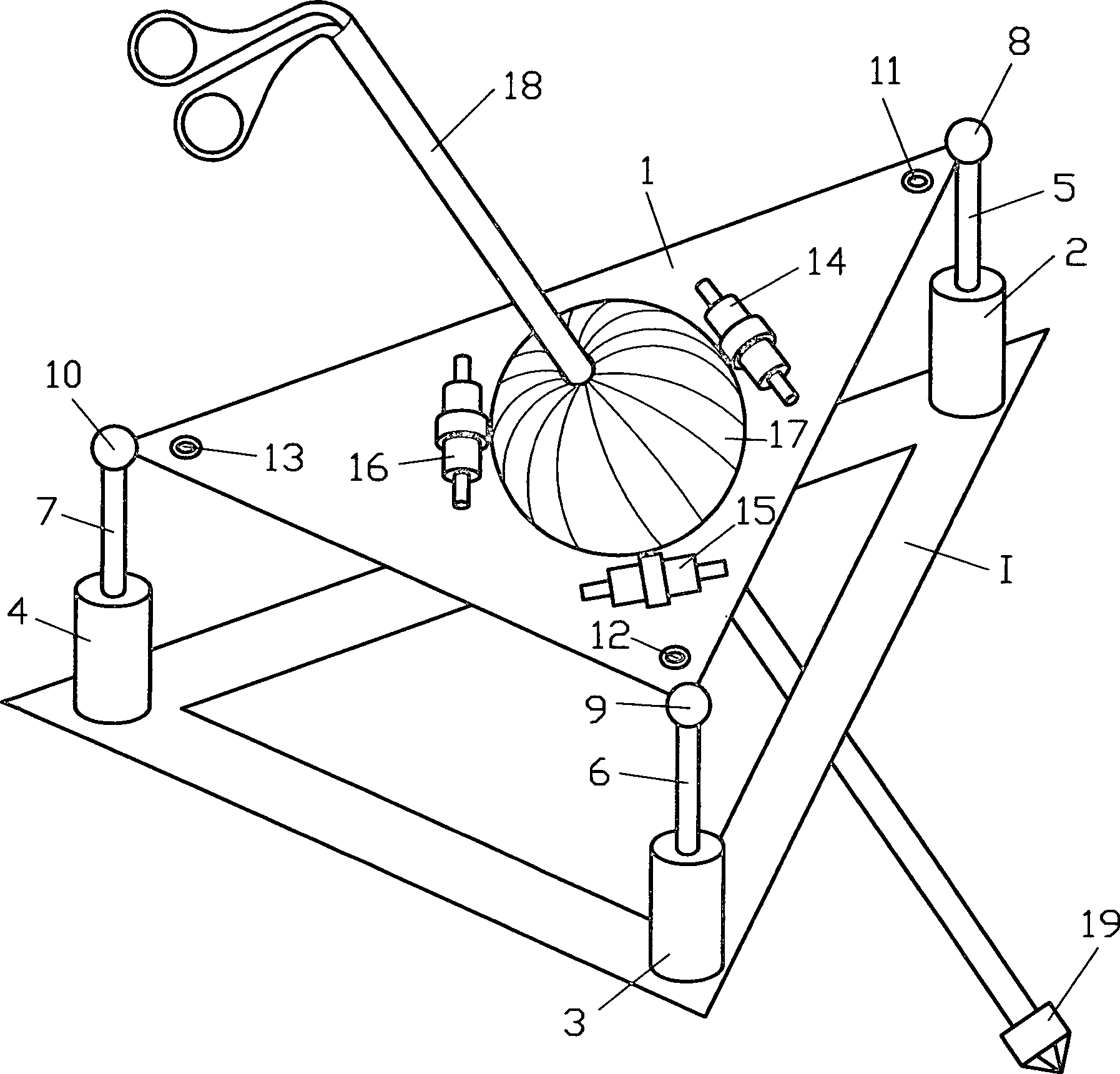
In claim 2 it is described that the frame is a circular ring, the inner circumferential surface of which is a spherical segment surface in which a ball slides in a form-fitting manner, through which the rod / tube projects polarly. Three ball or roller drives sit on the surface or the front of the frame and press against the ball. The axes of the three drives lie in one plane through the ball and form an equilateral triangle. With such a structure, the tube can already be pivoted in any direction of the double movement cone or pyramid. A rotor drive sits inside the ball for the rotation of the tube and a linear drive is anchored in it for the axial movement of the tube.
Anspruch 3 beschreibt, dass in die innere kreisförmige Mantelwand des Rahmens gleichverteilt um den Umfang elektrische Spulen mit je einem Polschuh eingelassen sind und die Mantelwandkontur Kugelsegmentform hat. In der Kreisebene des Rahmens sitzt ein in der inneren Mantelwand des Rahmens kugelgelagerter Ring, der an seiner äußeren Mantelfläche gleichverteilt um den Umfang Permanentmagnete in der Anzahl der nach außen gegenüberliegenden Spulen eingelassen hat. In dem Ring sitzt zentral ein Anker kugelgelagert, dessen beide Polschuhe mit je einer elektrischen Spule umwickelt sind, die mit ihrer jeweils radial nach außen gerichte ten Fläche auf einer zum Ring zentralen Kugelfläche liegen. Der Anker kann nur in einer senkrecht zur Kreisebene des Rahmens stehenden Ebene schwenken, und den beiden Polschuhen steht je ein Permanentmagnet gegenüber, die in die innere Mantelwand des Ringes unter Wahrung einer Kugelsegmentkontur eingelassen sind. Hier sitzt jetzt zentral zwischen den beiden Polschuhen des Ankers der Linearantrieb, durch den hindurch das Rohr ragt und axial gehemmt/bewegt wird.Claim 3 describes that in the inner circular Mantle wall of the frame evenly distributed around the circumference electrical Coils with one pole shoe each are embedded and the outer wall contour is spherical segment shape Has. In the circular plane of the frame sits in the inner wall of the frame ball-bearing ring, which is evenly distributed on its outer surface around the circumference of permanent magnets in the number of the opposite to the outside Has inserted coils. An anchor sits in the center of the ring with ball bearings, whose two pole pieces are wrapped with an electrical coil, with their radially outward facing surface a spherical surface central to the ring. The anchor can only be in a perpendicular to the circular plane of the frame swivel level, and the two pole pieces each have a permanent magnet across from, into the inner wall of the ring while maintaining a spherical segment contour are let in. Here sits between the two pole pieces of the armature is the linear drive through which the tube protrudes and axially is inhibited / moved.
Gemäß Anspruch 4 wird das Rohr über folgende
Einrichtung gehemmt/bewegt:
Im Rahmen lagert ein äußerer Schwenkrahmen,
der mit seiner Ebene aus der Ebene des Rahmens geschwenkt werden
kann, und die Schwenk-/Drehachse geht durch das Zentrum dieses Schwenkrahmens und
des Rahmens. Ii dem Schwenkrahmen sitzt ein Scheibenmotor oder sitzen
zwei Scheibenmotoren, dessen oder deren Achse auf der Schwenkachse liegt
oder liegen und form- als auch kraftschlüssig in den Rahmen ragt oder
ragen. Bei nur einem Motor sitzt anstelle des zweiten Motors eine
koaxial drehbare Welle. Im äußeren Schwenkrahmen
sitzt ein weiterer Scheibenmotor oder sitzen zwei weitere Scheibenmotoren,
dessen Achse oder deren Achsen in das Innere des Schwenkrahmens
ragt oder ragen. Sie liegen auf einer Geraden, welche die Schwenkachse
des ersten senkrecht schneidet und ebenfalls in der Kreisebene des
Rahmens liegt. Mindestens die Achse des einen Scheibenmotors mit
ins Innere des äußeren Schwenkrahmen
ragender Achse steckt in dem inneren Schwenkrahmen form und kraftschlüssig, durch
den hindurch das Rohr, axial geführt,
ragt. Im Falle zweier Scheibenmotoren mit ins Innere des äußeren Schwenkrahmens
ragenden Achsen steckt entweder die Achse des zweiten ebenfalls
koaxial im inneren Schwenkrahmen form und kraftschlüssig oder
der zweite Scheibenmotor dient als Axialbeweger für das Rohr,
indem ein/e am Rohr verankerte/s Seil/Kette über die Motorwelle umläuft. Im
oder am Schwenkrahmen sitzt ein Rotorantrieb, der das Rohr dreht.
Falls kein Scheibenmotor als Axialbeweger verwendet wird, sitzt
dafür im
oder am inneren Schwenkrahmen ein Linearantrieb.According to claim 4, the pipe is inhibited / moved via the following device:
An outer swivel frame, which can be swiveled with its plane out of the plane of the frame, is stored in the frame, and the swivel / rotation axis passes through the center of this swivel frame and the frame. In the swivel frame there is a disc motor or two disc motors, the axis of which lies or lie on the swivel axis and projects or projects positively and non-positively into the frame. With only one motor there is a coaxially rotatable shaft instead of the second motor. Another disc motor sits in the outer swivel frame or two further disc motors sit, the axis or axes of which are in the inside of the swing frame protrudes or protrudes. They lie on a straight line which perpendicularly intersects the pivot axis of the first and also lies in the circular plane of the frame. At least the axis of the one disc motor with the axis projecting into the interior of the outer swivel frame is in the inner swivel frame in a positive and non-positive manner, through which the pipe, axially guided, projects. In the case of two disc motors with axles projecting into the inside of the outer swivel frame, either the axis of the second, also coaxially, is stuck in the inner swivel frame in a positive and non-positive manner, or the second disc motor serves as an axial mover for the tube by a rope / chain anchored to the tube the motor shaft rotates. A rotor drive sits in or on the swivel frame and rotates the tube. If no disc motor is used as an axial mover, there is a linear drive in or on the inner swivel frame.
Nach Anspruch 5, der sich auf die Ansprüche 2 bis 4 bezieht, ist jeder Motor mit einem Positionsgeber versehen, damit die Stellung des jeweiligen Motors erfasst wird. Beispielsweise kann zu Beginn des Betriebs die Position des distalen Endes des Rohrs aufgenommen werden oder dasselbe wird bei Verwendung ein und desselben eingespannten Rohrs einmal erfasst.According to claim 5, which relates to the Claims 2 to 4, each motor is equipped with a position sensor, so that the position of the respective motor is recorded. For example the position of the distal end of the Pipe can be included or the same will be used when using one and of the same clamped pipe.
Zur Erfassung der Lage der Fläche in welcher der Rahmen eingespannt ist, sitzt mindestens ein dreidimensional empfindlicher Neigungssensor auf dieser. Mit ihm werden Neigungssignale erzeugt, die gegebenenfalls rechnerisch in einen Bewegungsablauf des Rohres mit einbezogen werden.To record the position of the surface in which the frame is clamped, sits at least one three-dimensionally sensitive tilt sensor on this. With it, tilt signals generated, which if necessary arithmetically in a motion sequence of the pipe.
Zur Hemmung oder zum Antrieb des Rohres und Mitverfolgung seiner Position wird eine elektronische Datenverarbeitungsanlage eingesetzt, in der die Signale zur kraft-/momentvorgegebenen Bewegungshemmung oder -forcierten Bewegung verarbeitet und die motorischen Antriebe leistungsmäßig entsprechend angesteuert werden.To inhibit or drive the Rohres and tracking his position becomes an electronic one Data processing system used, in which the signals for the force / moment specified Restricted movement or forced movement processed and the motor Drives according to performance can be controlled.
Die Einrichtung hat nicht nur die gleiche Funktionalität wie das zum Stande der Technik zitierte System, VMS, es ist darüber hinaus auch von den aufgeführten Mängeln frei. Es zeichnet sich durch einen einfachen Aufbau aus, besteht vollständig aus kommerziell erhältlichen Standardkomponenten und ist konstruktiv einfach aufgebaut. Darüber hinaus kann die Einrichtung die Bewegungen der aufgeblähten Bauchdecke simulieren und damit schon durch das Training an ihm das Realitätsgefühl entwickeln.The facility doesn't just have that same functionality like the prior art system, VMS, it is beyond also from those listed defects free. It is characterized by a simple structure, consists Completely from commercially available Standard components and is structurally simple. Furthermore, can the device simulates the movements of the inflated abdominal wall and thus develop a sense of reality through training on him.
Die Erweiterung der Simulation um die Nachbildung der elastischen Bauchdecke gestaltet die Simulation realistischer. Der einfache Aufbau geht mit einer hohen Robustheit einher und hält die Einrichtung kostengünstig. Die drei vorgestellten Realisierungen derselben sind bezüglich Aktion und Reaktion voll symmetrisch, daher kann das Gerät ohne Einschränkungen sowohl als reines Eingabegerät mit oder ohne Kraftrückkopplung als auch als Miniro boter, reines Ausgabe Gerät, benutzt werden. Die Einrichtung ist in verschiedenen Technikfeldern einsetzbar, als künstliches Gelenk, bei Roboter, Telemanipulatoren oder in der Medizin als Biopsiegerät beispielsweise. Hinsichtlich der Miniaturisierung sind die Grenzen noch nicht erreicht.The expansion of the simulation by the simulation creates the simulation of the elastic abdominal wall realistic. The simple structure is extremely robust hand in hand and holds the establishment inexpensively. The three realizations of the same presented are in relation to action and response fully symmetrical, therefore the device can be used without restrictions both as a pure input device with or without force feedback as well as a Miniro bot, pure output device. The facility can be used in various technical fields, as an artificial one Joint, in robots, telemanipulators or in medicine as a biopsy device, for example. The limits regarding miniaturization have not yet been reached.
Der ursprünglich ins Auge gefasste Verwendungszweck, nämlich das Trainieren/Simulieren der Bewegungsabläufe beim minimalinvasiven Operieren gestaltet sich lebendiger und realistischer. Schließlich sind solche Simulatoren durch ihre Robustheit und Ihren niedrigen Preis gewerblich breit verwendbar.The original intended use, namely training / simulating the movements during minimally invasive surgery is more lively and realistic. Finally are such simulators due to their robustness and low price widely used commercially.
Die Ausführungsformen werden im folgenden anhand der Zeichnung näher beschrieben.The embodiments are as follows based on the drawing described.
Es zeigen:Show it:
Das System kann aus einer oder mehreren schwebenden Platten, einem oder mehreren Ein-/Ausgabegeräten und dazu gehörigen Elektronik für die Positionsauswertung und für die Motorantriebe bestehen die alle über einen zentralen PC-System gesteuert werden.The system can be made up of one or more floating Plates, one or more input / output devices and associated electronics for position evaluation and for the motor drives are all controlled by a central PC system become.
Zur besseren Übersicht kann das Gesamtsystem
in zwei Untersysteme aufgeteilt werden:
Das erste Untersystem
besteht aus der Fläche/Platte
The first subsystem consists of the surface / plate
Für
die Ansteuerung der drei Servomotoren
Die Konstruktion der „schwebenden" Fläche
Beim Einwirken senkrecht zu der Platte
orientierter Kraftkomponenten werden die Servoantriebe
Das für die Positionsregelung der
Platte
Das zweite Untersystem besteht aus
der Nachbildung eines laparaskopischen Instruments mit dem dazu
zugehörigen
Stück des
Operationsumfelds. Das Instrument muß sich frei von störenden Trägheits-,
Zieh-, oder Reibungskräften
im Raum bewegen können.
Die Position der Instrumentenspitze
Eine konstruktive Alternative ist der angepaßte Scheibenläufermo tor oder, wenn die volle Drehung nicht notwendig ist, ein konstruktiv angepaßter Schwenkantrieb. Andere Drehmomentantriebe können ebenfalls eingesetzt/verwendet werden.A constructive alternative is the adapted Disc rotor motor or, if full rotation is not necessary, a constructive one adapted rotary actuator. Other torque drives can also be used.
Im Innern des Rotors sind zwei weitere
Direktservoantriebe eingebaut, ein Antrieb, der als Pendel-Motor
bezeichnet wird. Er kann einen an ihm befestigten Linear- Servomotor
um einen bestimmten Winkel (z.B. +/– 45°) um die Z-Achse pendeln lassen kann.
Der Antrieb kann je nach Anwendungsfall symmetrisch oder asymmetrisch
in dem runden Rotor befestigt werden. Der Läufer des Linearservomotors
Der Pendel-Antrieb kann z. B. ein normaler bürstenloser Servomotor sein, dessen Rotor am Ringläufer befestigt ist. Alternativ kommt ein angepaßter Schwenkantrieb in Frage.The pendulum drive can, for. B. a normal brushless Servo motor, whose rotor is attached to the ring traveler. alternative comes a customized one Swivel drive in question.
Obwohl sich die beiden Drehantriebe
immer nur um ihre Achse drehen können
und der Linearantrieb
Die Ausführung ist ein kompaktes und
einfaches Gebilde mit gleicher Funktionalität wie bei Geräten nach
dem Stande der Technik jedoch ohne die dort vorhandenen Schwachstellen.
Der Aufbau ist in der
Die Position der Spitze des Stabes/Rohrs
- II
- Konstruktionsrahmenstructural frame
- 11
- Fläche, PlatteSurface, plate
- 2,3,42,3,4
- Linearantrieb, ServomotorLinear actuator, servomotor
- 5,6,75,6,7
- Gelenkewellejoints wave
- 8,9,108,9,10
- federelastisches Element, Koppelelement, Ankerpunktresilient Element, coupling element, anchor point
- 11,12,1311,12,13
- Neigungssensortilt sensor
- 14,15,1614,15,16
- Kugel- oder WalzenantriebBullet- or roller drive
- 1717
- KugelBullet
- 1818
- Rohr/Stab, Längsachse, SchaftTube / rod, longitudinal axis, shaft
- 1919
- 3D-Sensor, Instrumentenspitze3D sensor, instrument tip
- 2020
- Rotationsantriebrotary drive
- 2121
- Linearantrieblinear actuator
- 2222
- Kugelführungball guide
- 2323
- Rahmenframe
- 2424
- Polschuhpole
- 2525
- SpuleKitchen sink
- 2626
- Permanentmagnetpermanent magnet
- 2727
- kugelgelagerter Ring, Rotor des Ringmotorsball bearing Ring, rotor of the ring motor
- 2828
- Anker mit Kugelsegmentkonturanchor with spherical segment contour
- 2929
- Scheibenmotorwheel motor
- 3030
- äußerer Schwenkrahmenouter swing frame
- 3131
- Zahnradgear
- 3232
- innerer Schwenkrahmeninternal swing frame
- 3333
- DatenverarbeitungsanlageData processing system
- 3434
- Servoverstärker für Kugel-/WalzenantriebServo amplifier for ball / roller drive
- 3535
- Servoverstärker für LinarantriebServo amplifier for linear drive
- 3636
- Auswerteelektronik für Neigungssensorenevaluation for inclination sensors
Claims (8)
Priority Applications (1)
| Application Number | Priority Date | Filing Date | Title |
|---|---|---|---|
| DE2003104736 DE10304736B3 (en) | 2003-02-06 | 2003-02-06 | Arrangement for moving a rod or tube within a virtual reality simulator for minimally invasive surgery has a mounting frame assembly and a simulator assembly with a rod or tube that is moved in a simulation manner |
Applications Claiming Priority (1)
| Application Number | Priority Date | Filing Date | Title |
|---|---|---|---|
| DE2003104736 DE10304736B3 (en) | 2003-02-06 | 2003-02-06 | Arrangement for moving a rod or tube within a virtual reality simulator for minimally invasive surgery has a mounting frame assembly and a simulator assembly with a rod or tube that is moved in a simulation manner |
Publications (1)
| Publication Number | Publication Date |
|---|---|
| DE10304736B3 true DE10304736B3 (en) | 2004-09-30 |
Family
ID=32920597
Family Applications (1)
| Application Number | Title | Priority Date | Filing Date |
|---|---|---|---|
| DE2003104736 Expired - Fee Related DE10304736B3 (en) | 2003-02-06 | 2003-02-06 | Arrangement for moving a rod or tube within a virtual reality simulator for minimally invasive surgery has a mounting frame assembly and a simulator assembly with a rod or tube that is moved in a simulation manner |
Country Status (1)
| Country | Link |
|---|---|
| DE (1) | DE10304736B3 (en) |
Cited By (10)
| Publication number | Priority date | Publication date | Assignee | Title |
|---|---|---|---|---|
| EP2068294A1 (en) * | 2007-12-03 | 2009-06-10 | Endosim Limited | Laparoscopic training apparatus |
| WO2009086714A1 (en) * | 2008-01-07 | 2009-07-16 | Weijian Chen | An endoscope simulation installment and its system and its simulation method. |
| CN102306471A (en) * | 2011-08-02 | 2012-01-04 | 陈为坚 | Improved endoscope simulation device |
| EP2738756A1 (en) * | 2012-11-30 | 2014-06-04 | Surgical Science Sweden AB | User interface device for surgical simulation system |
| EP2760003A1 (en) * | 2013-01-24 | 2014-07-30 | Surgical Science Sweden AB | Haptic user interface device for surgical simulation system |
| EP3046093A4 (en) * | 2013-11-29 | 2016-09-07 | Eidos Medicine Llc | Drive for generating force-related tactile feedback on an instrument |
| CN106530884A (en) * | 2016-12-23 | 2017-03-22 | 北京博医时代教育科技有限公司 | Bean-clamping simulator for laparoscopic technique training and use method for bean-clamping simulator |
| CN109171967A (en) * | 2018-09-30 | 2019-01-11 | 泗洪县正心医疗技术有限公司 | One kind can flexible curved surgical robotic apparatus |
| RU2679110C1 (en) * | 2017-11-29 | 2019-02-05 | Общество с ограниченной ответственностью "Эйдос - Медицина" | Ventriculoscope simulator |
| CN115157511A (en) * | 2022-06-19 | 2022-10-11 | 北京工业大学 | A device that can control the film thickness and uniformity of high-viscosity fluids |
Citations (5)
| Publication number | Priority date | Publication date | Assignee | Title |
|---|---|---|---|---|
| US5459382A (en) * | 1992-12-02 | 1995-10-17 | Cybernet Systems Corporation | Method and system for providing a tactile virtual reality and manipulator defining an interface device therefor |
| US20020033802A1 (en) * | 1994-07-14 | 2002-03-21 | Immersion Corporation | Physically realistic computer simulation of medical procedures |
| US6437771B1 (en) * | 1995-01-18 | 2002-08-20 | Immersion Corporation | Force feedback device including flexure member between actuator and user object |
| DE10055294C2 (en) * | 2000-11-03 | 2002-10-31 | Storz Karl Gmbh & Co Kg | Simulator device with at least two degrees of freedom of movement for use with a real instrument |
| WO2003009069A1 (en) * | 2001-07-16 | 2003-01-30 | Immersion Corporation | Interface apparatus with cable-driven force feedback and four grounded actuators |
-
2003
- 2003-02-06 DE DE2003104736 patent/DE10304736B3/en not_active Expired - Fee Related
Patent Citations (6)
| Publication number | Priority date | Publication date | Assignee | Title |
|---|---|---|---|---|
| US5459382A (en) * | 1992-12-02 | 1995-10-17 | Cybernet Systems Corporation | Method and system for providing a tactile virtual reality and manipulator defining an interface device therefor |
| US5459382B1 (en) * | 1992-12-02 | 1998-06-09 | Cybernet Systems Corp | Method and system for providing a tactile virtual reality and manipulator defining an interface device therefor |
| US20020033802A1 (en) * | 1994-07-14 | 2002-03-21 | Immersion Corporation | Physically realistic computer simulation of medical procedures |
| US6437771B1 (en) * | 1995-01-18 | 2002-08-20 | Immersion Corporation | Force feedback device including flexure member between actuator and user object |
| DE10055294C2 (en) * | 2000-11-03 | 2002-10-31 | Storz Karl Gmbh & Co Kg | Simulator device with at least two degrees of freedom of movement for use with a real instrument |
| WO2003009069A1 (en) * | 2001-07-16 | 2003-01-30 | Immersion Corporation | Interface apparatus with cable-driven force feedback and four grounded actuators |
Cited By (22)
| Publication number | Priority date | Publication date | Assignee | Title |
|---|---|---|---|---|
| EP2068294A1 (en) * | 2007-12-03 | 2009-06-10 | Endosim Limited | Laparoscopic training apparatus |
| EP2068295A3 (en) * | 2007-12-03 | 2010-07-14 | Endosim Limited | Laparoscopic training apparatus |
| US8328560B2 (en) | 2007-12-03 | 2012-12-11 | Endosim Limited | Laparoscopic apparatus |
| WO2009086714A1 (en) * | 2008-01-07 | 2009-07-16 | Weijian Chen | An endoscope simulation installment and its system and its simulation method. |
| US8157567B2 (en) | 2008-01-07 | 2012-04-17 | Chen Weijian | Endoscope simulation apparatus and system and method using the same to perform simulation |
| CN102306471A (en) * | 2011-08-02 | 2012-01-04 | 陈为坚 | Improved endoscope simulation device |
| CN102306471B (en) * | 2011-08-02 | 2013-11-06 | 陈为坚 | Improved endoscope simulation device |
| US9827050B2 (en) | 2012-11-30 | 2017-11-28 | Surgical Science Sweden Ab | User interface device for surgical simulation system |
| CN104823226A (en) * | 2012-11-30 | 2015-08-05 | 外科科学瑞典有限公司 | User interface device for surgical simulation system |
| CN104823226B (en) * | 2012-11-30 | 2017-03-08 | 外科科学瑞典有限公司 | User interface apparatus for surgical simulators system |
| WO2014083119A1 (en) * | 2012-11-30 | 2014-06-05 | Surgical Science Sweden Ab | User interface device for surgical simulation system |
| EP2738756A1 (en) * | 2012-11-30 | 2014-06-04 | Surgical Science Sweden AB | User interface device for surgical simulation system |
| EP2760003A1 (en) * | 2013-01-24 | 2014-07-30 | Surgical Science Sweden AB | Haptic user interface device for surgical simulation system |
| WO2014114636A1 (en) * | 2013-01-24 | 2014-07-31 | Surgical Science Sweden Ab | Haptic user interface device for surgical simulation system |
| US10559226B2 (en) | 2013-11-29 | 2020-02-11 | Eidos-Medicine Llc | Drive for generating force-related tactile feedback on an instrument |
| EP3046093A4 (en) * | 2013-11-29 | 2016-09-07 | Eidos Medicine Llc | Drive for generating force-related tactile feedback on an instrument |
| CN106530884A (en) * | 2016-12-23 | 2017-03-22 | 北京博医时代教育科技有限公司 | Bean-clamping simulator for laparoscopic technique training and use method for bean-clamping simulator |
| CN106530884B (en) * | 2016-12-23 | 2022-11-15 | 北京博医时代医疗科技有限公司 | Bean clamping simulator for laparoscopic technical training and using method thereof |
| RU2679110C1 (en) * | 2017-11-29 | 2019-02-05 | Общество с ограниченной ответственностью "Эйдос - Медицина" | Ventriculoscope simulator |
| CN109171967A (en) * | 2018-09-30 | 2019-01-11 | 泗洪县正心医疗技术有限公司 | One kind can flexible curved surgical robotic apparatus |
| CN115157511A (en) * | 2022-06-19 | 2022-10-11 | 北京工业大学 | A device that can control the film thickness and uniformity of high-viscosity fluids |
| CN115157511B (en) * | 2022-06-19 | 2023-09-12 | 北京工业大学 | Device capable of regulating and controlling film forming thickness and uniformity of high-viscosity fluid |
Similar Documents
| Publication | Publication Date | Title |
|---|---|---|
| DE69532536T2 (en) | DEVICE WITH MECHANICAL INPUT / OUTPUT FOR COMPUTER SYSTEMS WITH AN INTERFACE FOR FLEXIBLE LONG STRETCHED ITEMS | |
| EP1417547B1 (en) | Interface apparatus with cable-driven force feedback and four grounded actuators | |
| DE69631487T2 (en) | DEVICE FOR PROVIDING A COST-EFFECTIVE FORCED FEEDBACK AND MECHANICAL INPUT / OUTPUT FOR COMPUTER SYSTEMS | |
| DE10304736B3 (en) | Arrangement for moving a rod or tube within a virtual reality simulator for minimally invasive surgery has a mounting frame assembly and a simulator assembly with a rod or tube that is moved in a simulation manner | |
| DE69523323T2 (en) | SYSTEM FOR VIRTUAL REALITY AND FOR REMOTE REALITY | |
| CN104537938B (en) | Endoscope simulative training system capable of achieving flexible force feedback | |
| DE2401366A1 (en) | DISPLAY SYSTEM WITH POSITION INDICATOR | |
| EP2351001A1 (en) | Motion and orientation simulator | |
| DE69207083T2 (en) | Vibration simulator for a helicopter's propeller rotor | |
| DE102011102037B4 (en) | Full rotation Simulator | |
| DE102004046038B4 (en) | Virtual surgery simulator | |
| DE19503615A1 (en) | Two-dimensional joystick control unit | |
| EP1665022A1 (en) | Data recording device for data processing units | |
| EP2624914A1 (en) | Device for moving an object | |
| DE4402129A1 (en) | Movement and positioning device for computer simulation system | |
| DE112016003537T5 (en) | Device for reproducing the operating feeling | |
| CN101344997A (en) | Interface apparatus with cable-driven force feedback and four grounded actuators | |
| EP1666839A3 (en) | Motion and trajectory data generator for a multi-gimbaled rotating platform | |
| DE202018100806U1 (en) | Haptic remote control with permanently excited three-phase synchronous motor | |
| CN108346337A (en) | A kind of dual-purpose Surgery Simulation training device | |
| EP3356176A1 (en) | Wheel suspension of an electrical drive for supporting a manual movement impulse | |
| CN118968868B (en) | Shoulder joint looseness operation training model | |
| EP4009307B1 (en) | Device and system for simulating transcatheter operations | |
| DE736252C (en) | Method and device for toughness measurement | |
| DE202016008670U1 (en) | Haptic remote control with permanently excited three-phase synchronous motor |
Legal Events
| Date | Code | Title | Description |
|---|---|---|---|
| 8100 | Publication of the examined application without publication of unexamined application | ||
| 8364 | No opposition during term of opposition | ||
| 8339 | Ceased/non-payment of the annual fee |