DE10261334B4 - sewer pipe - Google Patents
sewer pipe Download PDFInfo
- Publication number
- DE10261334B4 DE10261334B4 DE10261334A DE10261334A DE10261334B4 DE 10261334 B4 DE10261334 B4 DE 10261334B4 DE 10261334 A DE10261334 A DE 10261334A DE 10261334 A DE10261334 A DE 10261334A DE 10261334 B4 DE10261334 B4 DE 10261334B4
- Authority
- DE
- Germany
- Prior art keywords
- pipe
- sewer pipe
- partial
- sewer
- shells
- Prior art date
- Legal status (The legal status is an assumption and is not a legal conclusion. Google has not performed a legal analysis and makes no representation as to the accuracy of the status listed.)
- Expired - Fee Related
Links
- 238000005553 drilling Methods 0.000 claims abstract description 20
- 239000002131 composite material Substances 0.000 claims abstract description 5
- 238000000034 method Methods 0.000 claims description 6
- 238000004519 manufacturing process Methods 0.000 claims description 5
- 238000007789 sealing Methods 0.000 claims description 5
- 230000005540 biological transmission Effects 0.000 claims description 2
- 239000003365 glass fiber Substances 0.000 claims description 2
- 238000009434 installation Methods 0.000 abstract 1
- 239000002689 soil Substances 0.000 description 7
- 230000000694 effects Effects 0.000 description 3
- 238000005304 joining Methods 0.000 description 3
- 230000008901 benefit Effects 0.000 description 2
- 238000005266 casting Methods 0.000 description 2
- 239000012530 fluid Substances 0.000 description 2
- 238000003780 insertion Methods 0.000 description 2
- 230000037431 insertion Effects 0.000 description 2
- 241000974840 Ellipes Species 0.000 description 1
- 230000009471 action Effects 0.000 description 1
- 150000001875 compounds Chemical group 0.000 description 1
- 238000010276 construction Methods 0.000 description 1
- 238000007796 conventional method Methods 0.000 description 1
- 238000010438 heat treatment Methods 0.000 description 1
- 238000001746 injection moulding Methods 0.000 description 1
- 230000003993 interaction Effects 0.000 description 1
- 239000000463 material Substances 0.000 description 1
- 230000007246 mechanism Effects 0.000 description 1
- 230000008569 process Effects 0.000 description 1
- 230000001681 protective effect Effects 0.000 description 1
Classifications
-
- B—PERFORMING OPERATIONS; TRANSPORTING
- B29—WORKING OF PLASTICS; WORKING OF SUBSTANCES IN A PLASTIC STATE IN GENERAL
- B29C—SHAPING OR JOINING OF PLASTICS; SHAPING OF MATERIAL IN A PLASTIC STATE, NOT OTHERWISE PROVIDED FOR; AFTER-TREATMENT OF THE SHAPED PRODUCTS, e.g. REPAIRING
- B29C65/00—Joining or sealing of preformed parts, e.g. welding of plastics materials; Apparatus therefor
- B29C65/56—Joining or sealing of preformed parts, e.g. welding of plastics materials; Apparatus therefor using mechanical means or mechanical connections, e.g. form-fits
-
- E—FIXED CONSTRUCTIONS
- E03—WATER SUPPLY; SEWERAGE
- E03F—SEWERS; CESSPOOLS
- E03F3/00—Sewer pipe-line systems
- E03F3/04—Pipes or fittings specially adapted to sewers
-
- B—PERFORMING OPERATIONS; TRANSPORTING
- B29—WORKING OF PLASTICS; WORKING OF SUBSTANCES IN A PLASTIC STATE IN GENERAL
- B29C—SHAPING OR JOINING OF PLASTICS; SHAPING OF MATERIAL IN A PLASTIC STATE, NOT OTHERWISE PROVIDED FOR; AFTER-TREATMENT OF THE SHAPED PRODUCTS, e.g. REPAIRING
- B29C65/00—Joining or sealing of preformed parts, e.g. welding of plastics materials; Apparatus therefor
- B29C65/56—Joining or sealing of preformed parts, e.g. welding of plastics materials; Apparatus therefor using mechanical means or mechanical connections, e.g. form-fits
- B29C65/58—Snap connection
-
- B—PERFORMING OPERATIONS; TRANSPORTING
- B29—WORKING OF PLASTICS; WORKING OF SUBSTANCES IN A PLASTIC STATE IN GENERAL
- B29C—SHAPING OR JOINING OF PLASTICS; SHAPING OF MATERIAL IN A PLASTIC STATE, NOT OTHERWISE PROVIDED FOR; AFTER-TREATMENT OF THE SHAPED PRODUCTS, e.g. REPAIRING
- B29C66/00—General aspects of processes or apparatus for joining preformed parts
- B29C66/01—General aspects dealing with the joint area or with the area to be joined
- B29C66/05—Particular design of joint configurations
- B29C66/10—Particular design of joint configurations particular design of the joint cross-sections
- B29C66/12—Joint cross-sections combining only two joint-segments; Tongue and groove joints; Tenon and mortise joints; Stepped joint cross-sections
- B29C66/124—Tongue and groove joints
- B29C66/1244—Tongue and groove joints characterised by the male part, i.e. the part comprising the tongue
- B29C66/12443—Tongue and groove joints characterised by the male part, i.e. the part comprising the tongue having the tongue substantially in the middle
-
- B—PERFORMING OPERATIONS; TRANSPORTING
- B29—WORKING OF PLASTICS; WORKING OF SUBSTANCES IN A PLASTIC STATE IN GENERAL
- B29C—SHAPING OR JOINING OF PLASTICS; SHAPING OF MATERIAL IN A PLASTIC STATE, NOT OTHERWISE PROVIDED FOR; AFTER-TREATMENT OF THE SHAPED PRODUCTS, e.g. REPAIRING
- B29C66/00—General aspects of processes or apparatus for joining preformed parts
- B29C66/01—General aspects dealing with the joint area or with the area to be joined
- B29C66/05—Particular design of joint configurations
- B29C66/10—Particular design of joint configurations particular design of the joint cross-sections
- B29C66/12—Joint cross-sections combining only two joint-segments; Tongue and groove joints; Tenon and mortise joints; Stepped joint cross-sections
- B29C66/124—Tongue and groove joints
- B29C66/1246—Tongue and groove joints characterised by the female part, i.e. the part comprising the groove
- B29C66/12461—Tongue and groove joints characterised by the female part, i.e. the part comprising the groove being rounded, i.e. U-shaped or C-shaped
-
- B—PERFORMING OPERATIONS; TRANSPORTING
- B29—WORKING OF PLASTICS; WORKING OF SUBSTANCES IN A PLASTIC STATE IN GENERAL
- B29C—SHAPING OR JOINING OF PLASTICS; SHAPING OF MATERIAL IN A PLASTIC STATE, NOT OTHERWISE PROVIDED FOR; AFTER-TREATMENT OF THE SHAPED PRODUCTS, e.g. REPAIRING
- B29C66/00—General aspects of processes or apparatus for joining preformed parts
- B29C66/01—General aspects dealing with the joint area or with the area to be joined
- B29C66/05—Particular design of joint configurations
- B29C66/10—Particular design of joint configurations particular design of the joint cross-sections
- B29C66/12—Joint cross-sections combining only two joint-segments; Tongue and groove joints; Tenon and mortise joints; Stepped joint cross-sections
- B29C66/126—Tenon and mortise joints
-
- B—PERFORMING OPERATIONS; TRANSPORTING
- B29—WORKING OF PLASTICS; WORKING OF SUBSTANCES IN A PLASTIC STATE IN GENERAL
- B29C—SHAPING OR JOINING OF PLASTICS; SHAPING OF MATERIAL IN A PLASTIC STATE, NOT OTHERWISE PROVIDED FOR; AFTER-TREATMENT OF THE SHAPED PRODUCTS, e.g. REPAIRING
- B29C66/00—General aspects of processes or apparatus for joining preformed parts
- B29C66/50—General aspects of joining tubular articles; General aspects of joining long products, i.e. bars or profiled elements; General aspects of joining single elements to tubular articles, hollow articles or bars; General aspects of joining several hollow-preforms to form hollow or tubular articles
- B29C66/51—Joining tubular articles, profiled elements or bars; Joining single elements to tubular articles, hollow articles or bars; Joining several hollow-preforms to form hollow or tubular articles
- B29C66/54—Joining several hollow-preforms, e.g. half-shells, to form hollow articles, e.g. for making balls, containers; Joining several hollow-preforms, e.g. half-cylinders, to form tubular articles
- B29C66/547—Joining several hollow-preforms, e.g. half-cylinders, to form tubular articles, e.g. endless tubes
-
- B—PERFORMING OPERATIONS; TRANSPORTING
- B29—WORKING OF PLASTICS; WORKING OF SUBSTANCES IN A PLASTIC STATE IN GENERAL
- B29C—SHAPING OR JOINING OF PLASTICS; SHAPING OF MATERIAL IN A PLASTIC STATE, NOT OTHERWISE PROVIDED FOR; AFTER-TREATMENT OF THE SHAPED PRODUCTS, e.g. REPAIRING
- B29C66/00—General aspects of processes or apparatus for joining preformed parts
- B29C66/50—General aspects of joining tubular articles; General aspects of joining long products, i.e. bars or profiled elements; General aspects of joining single elements to tubular articles, hollow articles or bars; General aspects of joining several hollow-preforms to form hollow or tubular articles
- B29C66/51—Joining tubular articles, profiled elements or bars; Joining single elements to tubular articles, hollow articles or bars; Joining several hollow-preforms to form hollow or tubular articles
- B29C66/54—Joining several hollow-preforms, e.g. half-shells, to form hollow articles, e.g. for making balls, containers; Joining several hollow-preforms, e.g. half-cylinders, to form tubular articles
- B29C66/549—Joining several hollow-preforms, e.g. half-shells, to form hollow articles, e.g. for making balls, containers; Joining several hollow-preforms, e.g. half-cylinders, to form tubular articles said hollow-preforms being interconnected during their moulding process, e.g. by a hinge
-
- E—FIXED CONSTRUCTIONS
- E21—EARTH OR ROCK DRILLING; MINING
- E21B—EARTH OR ROCK DRILLING; OBTAINING OIL, GAS, WATER, SOLUBLE OR MELTABLE MATERIALS OR A SLURRY OF MINERALS FROM WELLS
- E21B7/00—Special methods or apparatus for drilling
- E21B7/20—Driving or forcing casings or pipes into boreholes, e.g. sinking; Simultaneously drilling and casing boreholes
-
- F—MECHANICAL ENGINEERING; LIGHTING; HEATING; WEAPONS; BLASTING
- F16—ENGINEERING ELEMENTS AND UNITS; GENERAL MEASURES FOR PRODUCING AND MAINTAINING EFFECTIVE FUNCTIONING OF MACHINES OR INSTALLATIONS; THERMAL INSULATION IN GENERAL
- F16L—PIPES; JOINTS OR FITTINGS FOR PIPES; SUPPORTS FOR PIPES, CABLES OR PROTECTIVE TUBING; MEANS FOR THERMAL INSULATION IN GENERAL
- F16L55/00—Devices or appurtenances for use in, or in connection with, pipes or pipe systems
- F16L55/16—Devices for covering leaks in pipes or hoses, e.g. hose-menders
- F16L55/162—Devices for covering leaks in pipes or hoses, e.g. hose-menders from inside the pipe
- F16L55/165—Devices for covering leaks in pipes or hoses, e.g. hose-menders from inside the pipe a pipe or flexible liner being inserted in the damaged section
- F16L55/1658—Devices for covering leaks in pipes or hoses, e.g. hose-menders from inside the pipe a pipe or flexible liner being inserted in the damaged section the old pipe being ruptured prior to insertion of a new pipe
-
- F—MECHANICAL ENGINEERING; LIGHTING; HEATING; WEAPONS; BLASTING
- F16—ENGINEERING ELEMENTS AND UNITS; GENERAL MEASURES FOR PRODUCING AND MAINTAINING EFFECTIVE FUNCTIONING OF MACHINES OR INSTALLATIONS; THERMAL INSULATION IN GENERAL
- F16L—PIPES; JOINTS OR FITTINGS FOR PIPES; SUPPORTS FOR PIPES, CABLES OR PROTECTIVE TUBING; MEANS FOR THERMAL INSULATION IN GENERAL
- F16L9/00—Rigid pipes
- F16L9/22—Pipes composed of a plurality of segments
-
- B—PERFORMING OPERATIONS; TRANSPORTING
- B29—WORKING OF PLASTICS; WORKING OF SUBSTANCES IN A PLASTIC STATE IN GENERAL
- B29C—SHAPING OR JOINING OF PLASTICS; SHAPING OF MATERIAL IN A PLASTIC STATE, NOT OTHERWISE PROVIDED FOR; AFTER-TREATMENT OF THE SHAPED PRODUCTS, e.g. REPAIRING
- B29C66/00—General aspects of processes or apparatus for joining preformed parts
- B29C66/01—General aspects dealing with the joint area or with the area to be joined
- B29C66/05—Particular design of joint configurations
- B29C66/10—Particular design of joint configurations particular design of the joint cross-sections
- B29C66/12—Joint cross-sections combining only two joint-segments; Tongue and groove joints; Tenon and mortise joints; Stepped joint cross-sections
- B29C66/124—Tongue and groove joints
-
- B—PERFORMING OPERATIONS; TRANSPORTING
- B29—WORKING OF PLASTICS; WORKING OF SUBSTANCES IN A PLASTIC STATE IN GENERAL
- B29C—SHAPING OR JOINING OF PLASTICS; SHAPING OF MATERIAL IN A PLASTIC STATE, NOT OTHERWISE PROVIDED FOR; AFTER-TREATMENT OF THE SHAPED PRODUCTS, e.g. REPAIRING
- B29C66/00—General aspects of processes or apparatus for joining preformed parts
- B29C66/70—General aspects of processes or apparatus for joining preformed parts characterised by the composition, physical properties or the structure of the material of the parts to be joined; Joining with non-plastics material
- B29C66/72—General aspects of processes or apparatus for joining preformed parts characterised by the composition, physical properties or the structure of the material of the parts to be joined; Joining with non-plastics material characterised by the structure of the material of the parts to be joined
- B29C66/721—Fibre-reinforced materials
- B29C66/7212—Fibre-reinforced materials characterised by the composition of the fibres
-
- B—PERFORMING OPERATIONS; TRANSPORTING
- B29—WORKING OF PLASTICS; WORKING OF SUBSTANCES IN A PLASTIC STATE IN GENERAL
- B29L—INDEXING SCHEME ASSOCIATED WITH SUBCLASS B29C, RELATING TO PARTICULAR ARTICLES
- B29L2023/00—Tubular articles
- B29L2023/22—Tubes or pipes, i.e. rigid
Landscapes
- Engineering & Computer Science (AREA)
- Mechanical Engineering (AREA)
- General Engineering & Computer Science (AREA)
- Life Sciences & Earth Sciences (AREA)
- Mining & Mineral Resources (AREA)
- Geology (AREA)
- Hydrology & Water Resources (AREA)
- Public Health (AREA)
- Water Supply & Treatment (AREA)
- Health & Medical Sciences (AREA)
- Physics & Mathematics (AREA)
- Environmental & Geological Engineering (AREA)
- Fluid Mechanics (AREA)
- General Life Sciences & Earth Sciences (AREA)
- Geochemistry & Mineralogy (AREA)
- Sewage (AREA)
Abstract
Kanalrohr zum grabenlosen Verlegen im Erdreich durch Einschieben des Kanalrohrs mittels einer Rammvorrichtung oder Einziehen des Kanalrohrs mittels einer Bohrvorrichtung, dadurch gekennzeichnet, dass das Kanalrohr bezogen auf seinen Rohrumfang aneinandergesetzte Teilrohrschalen (1, 11, 12, 21, 22, 31, 32) und die Teilrohrschalen (1, 11, 12, 21, 22, 31, 32) untereinander fest verbindende Verbindungsmittel aufweist, wobei die Teilrohrschalen derart ausgestaltet sind, dass das aus Teilrohrschalen zusammengesetzte Kanalrohr endseitig zur Verbindung mit weiteren Kanalrohren oder mit einer Bohrvorrichtung geeignet ist, wobei hierfür Mittel zur Übertragung von Zugkräften vorgesehen sind.Sewer pipe for trenchless installation in the ground by inserting the sewer pipe by means of a piling device or pulling the sewer pipe by means of a drilling device, characterized in that the sewer pipe related to its pipe circumference adjoining sub-pipe shells (1, 11, 12, 21, 22, 31, 32) and the Partial pipe shells (1, 11, 12, 21, 22, 31, 32) interconnected firmly connecting means, wherein the sub-pipe shells are designed such that the composite of partial pipe shells sewer pipe end is suitable for connection to other sewer pipes or with a drilling device, for this purpose Means are provided for transmitting tensile forces.
Description
Die Erfindung betrifft ein Kanalrohr gemäß dem Oberbegriff des Patentanspruchs 1 sowie ein Verfahren zum Herstellen eines Kanalrohrstrangs gemäß dem Oberbegriff des Patentanspruchs 11.The The invention relates to a sewer pipe according to the preamble of the claim 1 and a method for producing a sewer pipe string according to the preamble of patent claim 11.
Kanalrohre werden in vielfältigen Formen und mit unterschiedlichen Verlegeverfahren in eine Erdumgebung eingebracht. Nachdem Kanalrohre zunächst im offenen Kanalbau verlegt wurden, werden nunmehr zunehmend Kanalrohre im sogenannten grabenlosen Verlegeverfahren in das Erdreich eingebracht. Hierzu wird das Kanalrohr beispielsweise unmittelbar in das Erdreich eingerammt oder durch eine Bohrvorrichtung in das Erdreich eingezogen. Dabei kann das Kanalrohr insbesondere mit einem Aufweitkopf in eine bestehende Pilotbohrung bzw. einen zu ersetzenden Altkanal eingezogen werden.sewer pipes be in diverse Shapes and with different laying methods in an earth environment brought in. After sewer pipes initially laid in the open canal construction were now increasingly sewer pipes in the so-called trenchless Laying method introduced into the soil. For this purpose, the sewer pipe for example, driven directly into the ground or through pulled a drilling device into the ground. It can do that Sewer pipe, in particular with an expansion head in an existing Pilot hole or be replaced to be replaced old channel.
Die beim grabenlosen Verlegen verwendeten Bohrköpfe weisen regelmäßig Anschlussleitungen auf, mit denen beispielsweise eine an dem Bohrkopf auszubringende Bohrflüssigkeit zu dem Bohrkopf geführt wird oder beispielsweise ein den Bohrkopf schlagend antreibendes Druckmedium dem Bohrkopf zugeführt wird.The Drilling heads used for trenchless laying regularly have connecting cables on, for example, one auszubringende on the drill head drilling fluid guided to the drill head or, for example, driving the drill head Pressure medium fed to the drill head becomes.
In der Regel wird beim grabenlosen Rohrverlegen das zu verlegende Rohr von einer Startgrube aus in das Erdreich eingebracht. Um die Ausmaße der auszuhebenden Startgrube möglichst gering zu halten, ist es bekannt, das Kanalrohr aus kurzen Rohrabschnitten zusammenzusetzen, die zur Bildung des Kanalrohrs zugfest miteinander verbunden werden können. Der jeweilige Rohrabschnitt wird zum Einbringen in das Erdreich in der Startgrube positioniert und in das Erdreich eingezogen oder eingeschoben. Somit sind die Ausmaße der Startgrube fast vollständig von der Länge des jeweiligen Rohrabschnitts abhängig.In The rule is in the trenchless pipe laying the pipe to be laid from a launch pit into the soil introduced. To the extent of the to be lifted Start pit possible To keep it low, it is known the sewer pipe made of short pipe sections composing, which tensile strength to each other to form the sewer pipe can be connected. The respective pipe section is for introduction into the soil positioned in the starting pit and pulled into the ground or inserted. Thus, the dimensions of the starting pit are almost completely from the length of the respective pipe section.
Wird das aus Rohrabschnitten zusammengesetzte Kanalrohr durch einen Bohrkopf, insbesondere einen Aufweitkopf, in die Erdumgebung eingebracht, und weist dieser Bohrkopf mit ihm verbundene Schlauchleitungen auf, so musste in der Vergangenheit zum effizienten Einbringen des Kanalrohrs zunächst jeder Rohrabschnitt auf die Schlauchleitungen aufgezogen werden, damit beim Einbringen des nächsten Rohrabschnitts die Schlauchleitungen nicht getrennt werden mussten. Daran ist nachteilig, dass während des gesamten Bohrvorgangs die auf die Schlauchleitungen aufgefädelten Rohre mitgeschleppt werden müssen. Dieses Mitführen der lose auf den Schlauchleitungen aufgefä delten Rohrabschnitte führt teilweise dazu, dass die losen Rohrabschnitte aneinanderstoßen und dadurch Schäden an den Rohrabschnitten hervorgerufen werden. Ferner ist eine Vorrichtung notwendig, um den jeweils als nächsten einzubringenden Rohrabschnitt mit dem bereits vor ihm eingebrachten Rohrabschnitt zugfest zu verbinden, damit der bereits eingezogene Rohrabschnitt den einzuziehenden Rohrabschnitt in das Erdreich einziehen kann. Diese Verbindungsvorrichtungen belasten die Rohrabschnitte stark und können ebenfalls zu Schäden an den Rohrabschnitten führen. Ferner sind separate Mittel notwendig, die die zu einem Rohrstrang zusammengefügten Rohrabschnitte zusammen an der Bohrvorrichtung halten, damit sich der Verbund nicht während des Einziehens in das Erdreich löst.Becomes the sewer pipe composed of pipe sections through a drill head, in particular a widening head, introduced into the earth environment, and this drill head has hose lines connected to it, In the past, for the efficient introduction of the sewer pipe, everyone first had to Pipe section are drawn onto the hose lines so that when introducing the next Pipe section, the hose lines did not have to be separated. It is disadvantageous that during of the entire drilling process, the tubes threaded onto the hoses must be dragged along. This carrying the loosely on the hose lines aufgefä punched pipe sections leads partially that the loose pipe sections abut and thereby damages be caused on the pipe sections. Further, a device necessary to each as next to be introduced pipe section with the already introduced before him To join the pipe section tensile strength, so that the already retracted Pipe section feed the pipe section to be pulled into the ground can. These connecting devices load the pipe sections strong and can also to damage lead to the pipe sections. Furthermore, separate means are necessary, which to a pipe string joined Hold pipe sections together at the drilling device so that themselves the composite is not during of being pulled into the ground.
Außerdem ist die Verlegung eines Kanalrohrs nach der herkömmlichen Methode sehr zeitaufwendig; insbesondere deshalb, weil die einzelnen Rohrabschnitte zunächst auf den Schlauch aufgefädelt werden müssen.Besides that is the laying of a sewer pipe by the conventional method very time consuming; especially because the individual pipe sections initially on Threaded the hose Need to become.
Vor diesem Hintergrund liegt der Erfindung die Aufgabe zugrunde, ein Kanalrohr vorzuschlagen, das auf einfache Weise in die Erdumgebung eingebracht werden kann.In front In this background, the invention is based on the object To propose sewer pipe, in a simple way in the earth environment can be introduced.
Diese Aufgabe wird durch den Gegenstand der unabhängigen Ansprüche gelöst. Vorteilhafte Ausgestaltungen sind in den Unteransprüchen angegeben.These The object is solved by the subject matter of the independent claims. Advantageous embodiments are in the subclaims specified.
Die Erfindung geht von dem Grundgedanken aus, das Rohr bezogen auf den Rohrumfang aus Teilstücken zusammenzusetzen. Auf diese Weise kann das Rohr unmittelbar an dem gewünschten Ort um einen Gegenstand gelegt werden, der durch das Kanalrohr führen soll, insbesondere eine Schlauchleitung. Indem das Kanalrohr nunmehr nicht von vorne herein einen geschlossenen Umfang aufweist, ist es nicht mehr notwendig, das Kanalrohr bzw. die ein Kanalrohr bildenden kleinen Kanalrohre (Rohrabschnitte) auf das durch das Kanalrohr führende Element aufzuschieben.The Invention is based on the idea, the tube based on the Pipe circumference of sections reassemble. In this way, the tube can be attached directly to the desired Place around an object to pass through the sewer pipe, in particular a hose line. By the sewer pipe not now from the outset has a closed perimeter, it is not more necessary, the sewer pipe or a sewer pipe forming small Pipe pipes (pipe sections) postpone to the leading through the sewer pipe element.
Das Kanalrohr weist aneinander gesetzte Teilrohrschalen auf, die untereinander durch Verbindungsmittel fest miteinander verbunden sind. Dabei ist vorzugsweise bei einem Kanalrohr mindestens eines der die den Kanalrohrumfang bildenden Teilrohrschalen verbindenden Verbindungsmittel lösbar ausgebildet, damit der Kanalrohrumfang geöffnet werden kann, um das Kanalrohr in eine einen Gegenstand umgreifende Position zu bringen.The Sewer pipe has set to sub-pipe shells, each other are firmly connected by connecting means. It is preferably at a sewer pipe at least one of the sewer pipe circumference detachable connection means connecting connecting partial tube shells, so that the sewer pipe circumference is opened can be to the sewer pipe into an object embracing Position.
Im Rahmen dieser Erfindung wird unter einem Kanalrohr insbesondere jeglicher Langkörper verstanden, der in ein Erdreich eingebracht werden kann. Dabei ist das Kanalrohr vorzugsweise ein Hohlkörper, insbesondere ein hohlzylindrischer Körper. Allerdings kann das Kanalrohr auch einen von einem zylindrischen Querschnitt abweichenden Quer schnitt, beispielsweise einen rechteckigen oder elliptischen Querschnitt aufweisen. Das Kanalrohr ist vorzugsweise als Abwasserrohr, Kabelkanal, Fernwärmerohr oder Gasrohr ausgebildet. Ferner ist das Kanalrohr in weiteren speziellen Ausgestaltungen als Schutzrohr für die Versorgungsleitungen einer Bohrvorrichtung oder als Drainagerohr ausbildet.In the context of this invention, a sewer pipe is understood in particular to be any long body which can be introduced into a soil. In this case, the sewer pipe is preferably a hollow body, in particular a hollow cylindrical body. However, the sewer pipe can also a cross deviating from a cylindrical cross-section, for example, a rectangular or ellip have cross-section. The sewer pipe is preferably designed as a sewer pipe, cable duct, district heating pipe or gas pipe. Further, the sewer pipe is formed in further specific embodiments as a protective tube for the supply lines of a drilling device or as a drainage pipe.
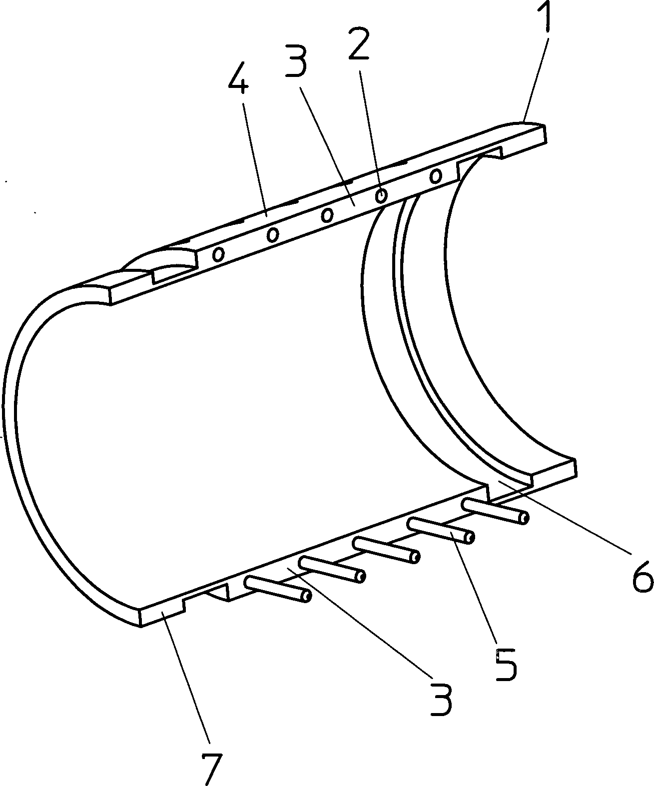
Als Teilrohrschalen werden insbesondere jegliche Elemente verstanden, die aneinander gesetzt werden können, um den Umfang eines Kanalrohrs zu bilden. Dabei sind die Teilrohrschalen vorzugsweise längliche, quer zur Längsrichtung gebogene Schalen, die an ihren Längskanten zur Bildung eines Rohrs zusammengesetzt werden können. Dabei können die Teilrohrschalen identische Ausmaße aufweisen oder aber zueinander unterschiedlich ausgebildet sein. Besonders bevorzugt wird das Kanalrohr aus zwei Halbrohrschalen zusammengesetzt.When Partial pipe shells are understood in particular to be any elements which can be put together to form the circumference of a sewer pipe. Here are the partial tube shells preferably elongated, transverse to the longitudinal direction curved shells attached to their longitudinal edges can be assembled to form a tube. The can Partial pipe shells have identical dimensions or to each other be formed differently. Particularly preferred is the sewer pipe composed of two half-pipe shells.
Als Verbindungsmittel werden insbesondere jegliche Mittel verstanden, die dazu geeignet sind, Teilrohrschalen zur Bildung eines Kanalrohrs miteinander zu verbinden. Dies können das zusammengesetzte Kanalrohr umgreifende Reifen oder Bänder sein, an Absätzen der Teilrohrschalen angreifende Schraubzwingen, in entsprechende Gewinde einer Teilrohrschale eingreifende Schraubverbindungen. Die Verbindungsmittel können die Teilrohrschalen nach dem Zusammensetzen des Kanalrohrs unlösbar fest miteinander verbinden, beispielsweise durch Fügeverfahren oder dadurch, dass die Verbindungsmittel bereits bei der Herstellung der Teilrohrschalen als einstückig mit den Teilrohrschalen hergestellte Verbindung, beispielsweise durch Urformen, beispielsweise ein Gießverfahren, hergestellt werden.When Lanyards are understood in particular to mean any means which are suitable for partial pipe shells to form a sewer pipe to connect with each other. This can be the composite sewer pipe encompassing hoops or bands, at paragraphs the Teilrohrschalen attacking screw clamps, in corresponding Thread of a sub-pipe shell engaging screw. The Lanyards can the sub-pipe shells after assembly of the sewer pipe insoluble fixed connect with each other, for example by joining methods or in that the connecting means already in the production of the partial pipe shells as one piece made with the sub-pipes connection, for example by prototyping, for example a casting process.
In einer vorteilhaften Ausgestaltung der Erfindung sind mindestens zwei Teilrohrschalen durch ein Scharnier miteinander verbunden. Diese feste Verbindung der Teilrohrschalen führt dazu, dass die so miteinander verbundenen Teilrohrschalen gemeinsam transportiert und gehandhabt werden können. Ferner bietet das Scharnier die Möglichkeit, die Teilrohrschalen einfach um den durch das Kanalrohr zu führenden Gegenstand zu legen. Das Scharnier kann bereits beim Herstellen der Teilrohrschalen erzeugt werden, beispielsweise durch Urformen, beispielsweise Gießen, einstückig mit den über das Scharnier zu verbindenden Teilrohrschalen hergestellt werden. Dadurch erzeugt das Scharnier eine dauerhafte Verbindung zwischen den Teilrohrschalen. Das Scharnier kann auch aus Komponenten bestehen, die einstückig mit den Teilrohrschalen hergestellt werden und die beispielsweise durch einen Steckmechanismus zu einem leicht lösbaren Scharnier verbunden werden. Dadurch können die Teilrohrschalen während des Transports einzeln und damit leichter gehandhabt werden, während die durch das lösbare Scharnier gebildete, belastbare Verbindung am Einsatzort leicht hergestellt werden kann.In An advantageous embodiment of the invention are at least two partial tube shells connected by a hinge. This fixed connection of the partial tube shells causes them to be so together connected sub-pipe shells transported and handled together can be. Furthermore, the hinge offers the possibility of the partial tube shells simply to lay the object to be led through the sewer pipe. The hinge can already be produced during the production of the partial pipe shells be, for example, by prototyping, for example, casting, integral with the over the hinge to be connected to sub-pipes are made. As a result, the hinge creates a permanent connection between the partial pipe shells. The hinge can also consist of components, the one-piece be made with the sub-pipes and the example connected by a plug-in mechanism to an easily detachable hinge become. Thereby can the partial pipe shells during the transport individually and thus be handled easier, while the through the detachable Hinge formed, durable connection at the job site easily can be produced.
Eine einfache Verbindung der Teilrohrschalen erfolgt durch mindestens ein Rastelement. Das Rastelement rastet vorzugsweise in einer Ausnehmung der anderen, mit der einen Teilrohrschale zu verbindenden Teilrohrschale ein. Als Rastelement wird dabei insbesondere jegliches Element verstanden, das eine Rastwirkung erzeugen kann, also beispielsweise einen Rücksprung aufweist, der in einen Vorsprung des durch Rasten zu verbindenden Elementes eingreifen kann.A simple connection of the partial pipe shells is carried out by at least a locking element. The latching element preferably engages in a recess the other, with the one part of the pipe shell to be connected pipe shell one. As a locking element is understood in particular any element, which can produce a detent effect, so for example a return having to be connected in a projection of the latching by Element can intervene.
Als Ausnehmung wird insbesondere das dem Rastelement entsprechende Gegenstück verstanden, das derart ausgebildet ist, dass das Rastelement an ihm eine Rastwirkung erzeugen kann. Insbesondere ist die Ausnehmung ein Rücksprung in der Außenoberfläche des einen Elements, den ein Vorsprung des Rastelements hintergreift. Als Ausnehmung wird beispielsweise auch ein Loch verstanden, in das ein beispielsweise nach Art eines Widerhakens ausgebildetes Rastelement eingreifen kann.When Recess is understood in particular the counterpart corresponding to the detent element, which is designed such that the latching element on it a locking action can generate. In particular, the recess is a return in the outer surface of the an element which engages behind a projection of the locking element. As a recess, for example, a hole understood, in for example, a trained in the manner of a barb Can engage locking element.
Die Teilrohrschale kann ein einzelnes Rastelement aufweisen. Dieses ist in einer bevorzugten Ausgestaltung als längliches Rastband ausgebildet. Die Teilrohrschale kann jedoch auch eine Vielzahl von Rastelementen aufweisen, beispielsweise durch Rastlöcher durchgreifende Raststifte. Ein Raststift kann beispielsweise ein Zylinderkörper oder auch ein flacher, schmaler Streifen sein.The Partial tube shell may have a single locking element. This is formed in a preferred embodiment as an elongated locking band. The However, part pipe shell can also be a variety of locking elements have, for example by detent holes by cross-locking pins. A latching pin can, for example, a cylinder body or a flat, be narrow strip.
Vorzugsweise ist das Rastelement schwenkbar mit der Teilrohrschale verbunden, um so eine flexiblere Handhabung des Rastelements zu ermöglichen. Insbesondere kann das Rastelement mit einem Scharnier schwenkbar mit einer Teilrohrschale verbunden sein, vorzugsweise einstückig mit der Teilrohrschale ausgebildet sein.Preferably the latching element is pivotally connected to the part pipe shell, so as to allow a more flexible handling of the locking element. In particular, the latching element can be pivoted with a hinge be connected to a partial tube shell, preferably in one piece with be formed of the partial tube shell.
Um das Zusammenfügen der Teilrohrschalen zu vereinfachen, weist eine Teilrohrschale vorzugsweise Positionierungshilfen, insbesondere Positionierungsstifte auf, die in Positionierungsausnehmungen einer weiteren Teilrohrschale eingreifen. Eine Positionierungshilfe ist insbesondere ein feststehendes, freistehendes Element einer Teilrohrschale, das durch das Zusammenwirken mit einer Ausnehmung einer anderen Teilrohrschale eine Positionierung der einen Teilrohrschale relativ zu der anderen Teilrohrschale beim Aneinandersetzen der Teilrohrschalen bewirkt.Around the joining together to simplify the sub-pipe shells, preferably has a partial pipe shell Positioning aids, in particular positioning pins, the engage in positioning recesses of a further part pipe shell. A Positioning aid is in particular a fixed, freestanding Element of a part of the pipe shell, through the interaction with a recess another part of the pipe shell, a positioning of a partial pipe shell relative to the other part of the pipe shell when placing the Teilrohrschalen causes.
Die Teilrohrschalen sind erfindungsgemäß derart ausgestaltet, dass das aus Teilrohrschalen zusammengesetzte Kanalrohr endseitig zur Verbindung mit weiteren Kanalrohren oder einer Bohrvorrichtung geeignet ist. Hierfür sind Mittel zur Übertragung von Zugkräften vorgesehen.The Partial pipe shells are inventively designed such that the composite of partial pipe shells sewer pipe end to Connection with other sewer pipes or a drilling device suitable is. Therefor are means of transmission of tensile forces intended.
In einer bevorzugten Ausgestaltung weist mindestens eine Teilrohrschale an der Innenoberfläche eine Ausnehmung auf. Diese Ausnehmung kann eine Erhebung aufnehmen, die an dem Element, mit dem das Kanalrohr zu verbinden ist, vorgesehen ist.In a preferred embodiment at least one partial tube shell on the inner surface of a recess. This recess can receive a survey, which is provided on the element with which the sewer pipe is to be connected.
Eine bevorzugte Ausgestaltung der Teilrohrschale sieht vor, dass endseitig, insbesondere an dem der Ausnehmung an der Innenoberfläche gegenüberliegenden Ende, an der Außenfläche mindestens eine Erhebung vorgesehen ist. Ein Kanalrohr, das zumindest eine derartige Teilrohrschale aufweist, ist selbst dazu geeignet, mit weiteren Kanalrohren verbunden zu werden. Auf diese Weise kann aus den einzelnen Kanalrohren ein Rohrstrang gebildet werden, indem das jeweils eine Kanalrohr das Ende des jeweils anderen Kanalrohrs umgreift, wobei die endseitige Erhebung des einen Kanalrohrs in die endseitige Ausnehmung des anderen Kanalrohrs eingreift.A preferred embodiment of the partial tube shell provides that the end, especially at the opposite of the recess on the inner surface End, on the outer surface at least a survey is provided. A sewer pipe, the at least one having such a partial tube shell is suitable even with to be connected to other sewer pipes. That way can off the individual sewer pipes a pipe string are formed by the one sewer pipe the end of each other sewer pipe encompasses, wherein the end elevation of a sewer pipe in the end recess of the other sewer pipe engages.
Zur Verbindung des Kanalrohrs mit anderen Elementen, insbesondere mit einer Bohrvorrichtung oder einem weiteren Kanalrohr, können an der Außenseite der Teilrohrschale bzw. an der Innenseite der Teilrohrschale Rastelemente vorgesehen sein, die beim Aufschieben des mit einer derartigen Teilrohrschale versehenen Kanalrohrs auf ein weiteres Element eine Zugkräfte übertragende Verbindung bildet. Insbesondere greifen die an der Außen- oder Innenseite vorgesehenen Rastelemente in Rastelemente ein, die an dem Element vorgesehen sind, mit dem das Kanalrohr zu verbinden ist. Vorzugsweise weist das Kanalrohr an dem einen Ende an der Außenseite Rastelemente auf, während es an dem anderen Ende an der Innenseite Rastelemente aufweist. Dadurch können einzelne Kanalrohre durch Ineinanderschieben fest miteinander verbunden werden.to Connection of the sewer pipe with other elements, in particular with a drilling device or another sewer pipe, on the outside the sub-pipe shell or on the inside of the part pipe shell locking elements Be provided when pushing the with such a partial tube shell provided sewer pipe to another element transmitting a tensile forces Compound forms. In particular, those on the outside or Inside provided locking elements in locking elements, the the element are provided to connect to the sewer pipe is. Preferably, the sewer pipe has at one end on the outside Locking elements on while it has latching elements on the inside at the other end. Thereby can individual sewer pipes connected by telescoping firmly together become.
Ein erfindungsgemäßer Kanalrohrstrang weist mindestens ein mit weiteren Kanalrohren verbundenes, zuvor beschriebenes Kanalrohr und eine zwischen den Kanalrohren angeordnete Dichtung auf. Insbesondere kann ein O-Ring vorgesehen sein, der das eine aus Teilrohrschalen zusammengesetzte Rohr gegenüber einem angrenzenden Rohr abdichtet.One inventive sewer pipe has at least one connected to other sewer pipes, previously described Sewer pipe and arranged between the sewer pipes seal. In particular, an O-ring may be provided, which is the one of partial tube shells Composed tube opposite seals an adjacent pipe.
Um als Transportmittel für Fluide dienen zu können, weist eine vorteilhafte Ausgestaltung des erfindungsgemäßen Kanalrohrs zwischen den Teilrohrschalen angeordnete Dichtelemente auf. Dabei können die Dichtelemente insbesondere an den Kontaktflächen der aneinander gesetzten Teilrohrschalen sowie an einer an den Teilrohrschalen vorgesehen Ausnehmung vorgesehen sein. Die Dichtelemente können in Ausnehmungen eingelegte, separate Dichtungskörper sein. Ergänzend oder alternativ können die Teilrohrschalen derart ausgebildet sein, dass sie beim Zusammenfügen eine Dichtwirkung, beispielsweise durch eine Quetschdichtung, erzeugen. Hierzu kann die Positionierungshilfe, insbesondere eine Positionierungskante, derart ausgebildet sein, dass sie in eine Nut einer weiteren Teilrohrschale eingreift.Around as a means of transport for To be able to serve fluids has an advantageous embodiment of the sewer pipe according to the invention arranged between the sub-pipe shells sealing elements. there can the sealing elements in particular at the contact surfaces of the juxtaposed Partial pipe shells and provided on one of the partial pipe shells Be provided recess. The sealing elements can be inserted in recesses, separate sealing body be. additional or alternatively, the Partial pipe shells be designed so that they when joining a Seal effect, for example, by a pinch seal produce. For this purpose, the positioning aid, in particular a positioning edge, be formed such that it into a groove of a further part of the pipe shell intervenes.
Das Kanalrohr kann zumindest teilweise aus Kunststoff hergestellt sein. Insbesondere sind die Teilrohrschalen verbindenden Rastelemente aus Kunststoff hergestellt. Dadurch weisen diese die nötige Flexibilität auf, um die Rastwirkung einfach erzeugen zu können. Ferner bietet diese Materialwahl den Vorteil, dass die Teilrohrschalen im Spritzgussverfahren hergestellt werden können. Insbesondere kann ein Kanalrohr, das Teilrohrschalen aufweist, die bereits während der Herstellung durch Filmescharniere miteinander verbunden werden, und das nur zur Verbindung zweier Teilrohrschalen an einer Seite Rastelemente aufweist, in einem einstückig hergestellt werden.The Sewer pipe may be at least partially made of plastic. In particular, the partial tube shells connecting locking elements made of plastic. As a result, they have the necessary flexibility to to be able to easily generate the locking effect. Furthermore, this choice of materials offers the Advantage that the partial pipe shells produced by injection molding can be. In particular, a sewer pipe having sub-pipe shells that already while the production are connected by film hinges, and only for the connection of two partial tube shells on one side locking elements has, in one piece getting produced.
Damit das Kanalrohr den auf es wirkenden Belastungen während des Einbringens in das Erdreich und nach dem Verlegen in dem Erdreich standhalten kann, ist es vorzugsweise mit Glasfasern verstärkt.In order to the sewer pipe the loads acting on it during insertion into the Soil and after laying in the soil can withstand it is preferably reinforced with glass fibers.
Das erfindungsgemäße Kanalrohr kann endseitig mit einer Bohrvorrichtung verbunden sein und mit der Bohrvorrichtung in eine Erdumgebung eingezogen werden. Dabei wird unter einer Bohrvorrichtung jegliche Vorrichtung verstanden, die dazu geeignet ist, ein Kanalrohr in eine Erdumgebung einzuziehen. Insbesondere sind dies selbst angetriebene Bohrvorrichtungen, Schlagbohrvorrichtungen oder mittels Zugseile oder Schubgestänge vorgetriebene Aufweitköpfe.The sewer pipe according to the invention can be connected end to end with a drilling device and with the drilling device are drawn into an earth environment. there is understood under a drilling device any device which is suitable for feeding a sewer pipe into an earth environment. In particular, these are self-propelled drilling devices, impact drills or expander heads driven by pull ropes or push rods.
Ein erfindungsgemäßes System aus Teilrohrschalen ist derart ausgebildet, dass die Teilrohrschalen zu einem Rohr mit bezogen auf den Rohrumfang aneinandergesetzten Teilrohrschalen zusammengesetzt werden können und die untereinander mit Verbindungsmitteln fest verbunden werden können. Dieses System aus Teilrohrschalen kann im Verhältnis zu einem geschlossenen Rohr leicht gehandhabt werden.One inventive system From sub-pipe shells is designed such that the sub-pipe shells to a pipe with respect to the tube circumference set one another Partial pipe shells can be assembled and with each other Lanyards can be firmly connected. This system of partial pipe shells can in proportion be easily handled to a closed tube.
Ein Kanalrohrstrang mit mindestens einem zuvor beschriebenen Kanalrohr wird gemäß einem erfindungsgemäßen Verfahren hergestellt, in dem die ein erstes Kanalrohr bildenden Teilrohrschalen das Ende eines zweiten Kanalrohr umgreifend angesetzt und mittels der Verbindungsmittel untereinander fest verbunden werden. Insbesondere werden mindestens zwei durch ein Scharnier verbundene Teilrohrschalen das Ende des zweiten Kanalrohrs umgreifend angesetzt und zusammengeklappt.One Sewer pipe with at least one sewer pipe described above is according to a method of the invention made in which the first sewer pipe forming part pipe shells the end of a second sewer pipe embracing recognized and means the connecting means are firmly connected to each other. Especially be at least two connected by a hinge pipe shells the end of the second sewer pipe embraced and folded folded.
Das erfindungsgemäße Kanalrohr kann dazu verwendet werden, mit weiteren Kanalrohren eine längere Kanalleitung zu bilden. Dazu wird nach dem Einziehen des ersten Kanalrohres ein zweites Kanalrohr mit dem freien Ende des ersten Kanalrohrs verbunden und dieses zweite Kanalrohr dann durch die Bohrvorrichtung in das erste Kanalrohr in die Erdumgebung eingezogen. Dies kann insbesondere aus einer Startgrube erfolgen.The sewer pipe according to the invention can be used to further with sewer pipes to form longer channel line. For this purpose, after drawing in the first sewer pipe, a second sewer pipe is connected to the free end of the first sewer pipe and this second sewer pipe is then drawn through the drilling device into the first sewer pipe into the earth's environment. This can be done in particular from a starting pit.
Ebenso kann jedoch das Kanalrohr von der Erdoberfläche aus in die Erdumgebung eingezogen werden.As well However, the sewer pipe from the earth's surface into the earth's environment be confiscated.
Das einzubringende Kanalrohr wird zum Verbinden mit der Bohrvorrichtung bzw. einem bereits eingebrachten Kanalrohr bevorzugt unmittelbar vor dem Einbringen in das Erdreich aus Teilrohrschalen zusammengesetzt. Dadurch wird verhindert, dass die einzubringenden Kanalrohre beispielsweise auf eine Schlauchleitung aufgefädelt werden müssen und mit der Schlauchleitung gehandhabt werden müssen. Ferner bietet das unmittelbar vor dem Einbringen stattfindende Zusammensetzen den Vorteil, dass das einzubringende Kanalrohr in schmaleren Teilabschnitten gehandhabt werden kann. So kann insbesondere ein Rohr mit großem Querschnitt durch kleinere Öffnungen, beispielsweise Mannlöcher, in Stücken durchgereicht werden und erst danach zusammengesetzt werden. Ferner können die Teilrohrschalen im Verhältnis zu einem bestehenden Kanalrohr mit festem Umfang besser, insbesondere mit geringerem Transportraum transportiert werden.The to be introduced sewer pipe is used for connection with the drilling device or an already introduced sewer pipe preferably immediately assembled prior to introduction into the soil from Teilrohrschalen. This prevents that the sewer pipes to be introduced, for example Threaded onto a hose line Need to become and must be handled with the hose line. Furthermore, it offers immediate pre-insertion assembly has the advantage that handled the sewer pipe to be introduced in narrower sections can be. In particular, a tube with a large cross section through smaller openings, for example manholes, in pieces be passed on and only then assembled. Further can the partial pipe shells in proportion to an existing sewer pipe with a fixed perimeter better, in particular be transported with a smaller transport space.
Das erfindungsgemäße Kanalrohr kann ferner durch eine Rammvorrichtung in das Erdreich eingerammt werden.The sewer pipe according to the invention can also be driven by a piling device in the ground become.
Nachfolgend wird die Erfindung anhand eines in der Zeichnung dargestellten Ausführungsbeispiels näher erläutert. In der Zeichnung zeigen:following the invention with reference to an embodiment shown in the drawing explained in more detail. In show the drawing:
Die
in
Die
Teilrohrschale
Die
in
Das
in
Ferner
weist das Kanalrohr
Das
Kanalrohr
Das
in
Claims (12)
Priority Applications (5)
| Application Number | Priority Date | Filing Date | Title |
|---|---|---|---|
| DE10261334A DE10261334B4 (en) | 2002-12-28 | 2002-12-28 | sewer pipe |
| AU2003300222A AU2003300222A1 (en) | 2002-12-28 | 2003-12-22 | Sewer pipe |
| GB0513201A GB2411448B (en) | 2002-12-28 | 2003-12-22 | Sewer pipe |
| PCT/EP2003/014738 WO2004059201A1 (en) | 2002-12-28 | 2003-12-22 | Sewer pipe |
| US10/540,988 US20060153640A1 (en) | 2002-12-28 | 2003-12-22 | Sewer pipe |
Applications Claiming Priority (1)
| Application Number | Priority Date | Filing Date | Title |
|---|---|---|---|
| DE10261334A DE10261334B4 (en) | 2002-12-28 | 2002-12-28 | sewer pipe |
Publications (2)
| Publication Number | Publication Date |
|---|---|
| DE10261334A1 DE10261334A1 (en) | 2004-07-15 |
| DE10261334B4 true DE10261334B4 (en) | 2010-04-15 |
Family
ID=32519429
Family Applications (1)
| Application Number | Title | Priority Date | Filing Date |
|---|---|---|---|
| DE10261334A Expired - Fee Related DE10261334B4 (en) | 2002-12-28 | 2002-12-28 | sewer pipe |
Country Status (5)
| Country | Link |
|---|---|
| US (1) | US20060153640A1 (en) |
| AU (1) | AU2003300222A1 (en) |
| DE (1) | DE10261334B4 (en) |
| GB (1) | GB2411448B (en) |
| WO (1) | WO2004059201A1 (en) |
Families Citing this family (15)
| Publication number | Priority date | Publication date | Assignee | Title |
|---|---|---|---|---|
| US6854230B2 (en) * | 2003-03-13 | 2005-02-15 | Charles Starke | Continuous structural wall system |
| DE102007004682A1 (en) * | 2007-01-25 | 2008-07-31 | Lic Langmatz Gmbh | Pipe, particularly bent pipe, has multiple pipe sections, which are inserted and fixed in connecting elements with their edge sections, and connecting elements that are foldable and formed for receiving pipe sections |
| NZ579184A (en) * | 2007-02-21 | 2012-07-27 | Orc Technology Pty Ltd | A vented sewer overflow device preventing water entering the sewer but allowing an overflow to push it off |
| EP1967355A1 (en) * | 2007-03-06 | 2008-09-10 | Pipelife Nederland B.V. | Method and apparatus for manufacturing a pipe from pipe segments |
| EP2000724B1 (en) * | 2007-06-07 | 2009-11-25 | Profilspecialisten AB | Male and female coupling member, pipe module and method for manufacturing the pipe module |
| US8292263B1 (en) * | 2008-12-11 | 2012-10-23 | George Rozsavolgyi | Manhole pipe shunt device |
| GB2469480A (en) * | 2009-04-15 | 2010-10-20 | Elkington Gatic | Foldable Slot Drain |
| US20150044402A1 (en) * | 2012-03-23 | 2015-02-12 | Cutting Dynamics, Inc. | Snap together structural component |
| DE202012003241U1 (en) * | 2012-03-30 | 2013-07-01 | EWKtec GmbH | Collector pipe and manifold system of a surface heating system and surface heating system |
| DE102012108389A1 (en) * | 2012-09-10 | 2014-05-28 | ACO Severin Ahlmann GmbH & Co Kommanditgesellschaft | slot channel |
| CN103542201B (en) * | 2013-09-29 | 2016-05-04 | 阳文皇 | Spliced compound tube misplaces |
| CN106547744B (en) * | 2015-09-16 | 2020-11-06 | 杭州海康威视数字技术股份有限公司 | Image retrieval method and system |
| EP3397831B1 (en) * | 2016-03-29 | 2024-09-11 | Herrenknecht AG | Drill pipe, and system and method for laying a pipeline |
| KR102095690B1 (en) * | 2017-02-16 | 2020-03-31 | 니찌아스 카부시키카이샤 | Heat conducting coating of piping system, heating device of piping system, manufacturing method of heat conducting coating and its attachment method, and manufacturing method of heating device and attachment method thereof |
| CN115388268B (en) * | 2022-08-09 | 2025-06-20 | 航天科工智能机器人有限责任公司 | A pipe feeding device and a robot pipe feeding method |
Citations (6)
| Publication number | Priority date | Publication date | Assignee | Title |
|---|---|---|---|---|
| DE16617C (en) * | J. GRETHER, Inhaber der Firma GRETHER & CO. in Freiburg, Breisgau | Transportable iron mold core for the production of sewer pipes from cement | ||
| DE49997C (en) * | R. BEER, Stadtbauinspektor in Magdeburg | Sewer locks | ||
| GB391181A (en) * | 1931-07-21 | 1933-04-21 | Gomer Lewis Watkins | Improvements in or relating to earthenware and stoneware tubes, pipes, gullies and the like |
| US2005699A (en) * | 1934-03-01 | 1935-06-18 | Ric Wil Company | Conduit and like construction |
| DE3609965A1 (en) * | 1985-03-27 | 1986-10-09 | Carlos Joaquim Costa Martins de Lissabon/Lisboa Oliveira | PRE-MADE DRAINAGE TUBE |
| DE29813896U1 (en) * | 1998-07-23 | 1998-10-22 | Berliner Wasserbetriebe Anstalt des öffentlichen Rechts, 10713 Berlin | Half-shells for the partial replacement of drainage channels |
Family Cites Families (17)
| Publication number | Priority date | Publication date | Assignee | Title |
|---|---|---|---|---|
| US4286640A (en) * | 1980-01-21 | 1981-09-01 | Abbott Laboratories | Tamperproof port cover |
| US4340052A (en) * | 1980-10-07 | 1982-07-20 | Baxter Travenol Laboratories, Inc. | Connection site protector |
| CA1164816A (en) * | 1981-07-10 | 1984-04-03 | Duratron Systems Limited | Method of relining sewers and water lines without excavation |
| US5078430A (en) * | 1981-07-10 | 1992-01-07 | Duratron Systems Limited | Pipeline for relining sewers and water lines without excavation |
| DE3407381C3 (en) * | 1984-02-29 | 1995-11-09 | Zueblin Ag | Method of laying an underground pipeline and device for carrying out such a method |
| US4826215A (en) * | 1986-12-01 | 1989-05-02 | Sullivan Samuel R | Clamp |
| US4779902A (en) * | 1987-07-06 | 1988-10-25 | Mid-Continent Pipe & Supply Co., Inc. | Plastic pipe with integral end connection |
| DE4105266A1 (en) * | 1991-02-20 | 1992-08-27 | Kirchner Fraenk Rohr | PIPE CONNECTION FOR WELL PIPES |
| US5531695A (en) * | 1994-12-22 | 1996-07-02 | Sherwood Medical Company | Tamper evident sleeve |
| DE19749007C2 (en) * | 1997-11-06 | 1999-08-12 | Tracto Technik | Device for connecting a draw tube with a drawing device |
| DE19922813C2 (en) * | 1999-02-23 | 2001-03-29 | Tracto Technik | Automatic boom |
| US6311734B1 (en) * | 1999-11-12 | 2001-11-06 | Alsons Corporation | Showerhead security cover |
| US6227251B1 (en) * | 2000-02-29 | 2001-05-08 | Composites Industrial Service Co., Ltd | Wire protecting structure |
| GB0027521D0 (en) * | 2000-11-10 | 2000-12-27 | Coniston Holdings Ltd | Pipe construction system |
| DE50206281D1 (en) * | 2001-05-07 | 2006-05-18 | Elkuch Ganter Wilma | repair pipe |
| GB2388640B (en) * | 2002-05-15 | 2005-02-02 | Crp Group Ltd | Protective ducting |
| US6916051B2 (en) * | 2003-02-13 | 2005-07-12 | Medical Components, Inc. | Coupler for a flexible tube |
-
2002
- 2002-12-28 DE DE10261334A patent/DE10261334B4/en not_active Expired - Fee Related
-
2003
- 2003-12-22 US US10/540,988 patent/US20060153640A1/en not_active Abandoned
- 2003-12-22 GB GB0513201A patent/GB2411448B/en not_active Expired - Fee Related
- 2003-12-22 WO PCT/EP2003/014738 patent/WO2004059201A1/en not_active Ceased
- 2003-12-22 AU AU2003300222A patent/AU2003300222A1/en not_active Abandoned
Patent Citations (6)
| Publication number | Priority date | Publication date | Assignee | Title |
|---|---|---|---|---|
| DE16617C (en) * | J. GRETHER, Inhaber der Firma GRETHER & CO. in Freiburg, Breisgau | Transportable iron mold core for the production of sewer pipes from cement | ||
| DE49997C (en) * | R. BEER, Stadtbauinspektor in Magdeburg | Sewer locks | ||
| GB391181A (en) * | 1931-07-21 | 1933-04-21 | Gomer Lewis Watkins | Improvements in or relating to earthenware and stoneware tubes, pipes, gullies and the like |
| US2005699A (en) * | 1934-03-01 | 1935-06-18 | Ric Wil Company | Conduit and like construction |
| DE3609965A1 (en) * | 1985-03-27 | 1986-10-09 | Carlos Joaquim Costa Martins de Lissabon/Lisboa Oliveira | PRE-MADE DRAINAGE TUBE |
| DE29813896U1 (en) * | 1998-07-23 | 1998-10-22 | Berliner Wasserbetriebe Anstalt des öffentlichen Rechts, 10713 Berlin | Half-shells for the partial replacement of drainage channels |
Also Published As
| Publication number | Publication date |
|---|---|
| GB2411448A (en) | 2005-08-31 |
| AU2003300222A1 (en) | 2004-07-22 |
| GB2411448A9 (en) | 2005-09-05 |
| US20060153640A1 (en) | 2006-07-13 |
| GB2411448B (en) | 2006-10-04 |
| WO2004059201A1 (en) | 2004-07-15 |
| DE10261334A1 (en) | 2004-07-15 |
| GB0513201D0 (en) | 2005-08-03 |
Similar Documents
| Publication | Publication Date | Title |
|---|---|---|
| DE10261334B4 (en) | sewer pipe | |
| DE69911464T2 (en) | PIPE CONNECTION | |
| DE2832614A1 (en) | CONNECTING PIECE FOR PIPING | |
| DE4031949C2 (en) | Method and device for the rehabilitation of sewers | |
| EP1312848A1 (en) | Pipe coupling and method to achieve a pipe coupling | |
| EP1375114A2 (en) | Process for joining first and second synthetic pipes and pipe | |
| EP3043101B1 (en) | Sealing sleeve | |
| DE102011001607A1 (en) | Quick connector for the production of detachable hose and / or pipe connections | |
| DE3129870A1 (en) | Method for repairing pipeline systems laid underground and a device for carrying out the method | |
| DE102005014339B3 (en) | Plastic pipe for pipe renovating pipe systems has male and female connectors with melting areas at outer and inner ends of coupling areas and metal component at contact point between two melting areas | |
| DE19749007A1 (en) | Connection joining e.g. a ram drilling head with the pipeline pulled after it | |
| DE102006034652B4 (en) | Packer for pipe and sewer rehabilitation | |
| EP0436060B1 (en) | Method of relining of cavities, especially for the renovation of damaged ducts and pipelines | |
| EP3339704A1 (en) | Method for producing a pipe connection and pipe for use in such a method | |
| DE202010003282U1 (en) | Device for connecting a metal pipe to a plastic pipe | |
| DE102009012613B4 (en) | Method and device for introducing a pipe into a hole in the ground | |
| DE102017103758A1 (en) | Method for introducing a pipe into a substrate and placing a pipe in the substrate | |
| EP3517688B1 (en) | Ground anchor element | |
| DE4010234A1 (en) | Pipe connection esp. for cable protection conduits - has inner and outer side smooth wall course in region of pipe connection places suitable for transmitting traction | |
| WO2004053285A1 (en) | Method and device for drilling a channel | |
| DE102008016330A1 (en) | Protective pipe system for cable installed in ground, has insertion slots designed in inner and outer pipe sections, respectively, for line to be incorporated, where slot widths of respective insertion slots correspond to each other | |
| DE10241610B4 (en) | Adapter for connecting a pipeline to be recovered with a pulling device | |
| DE202011104951U1 (en) | Weight element for weighing geothermal probes | |
| DE102007013560B4 (en) | Adjustable segmental arch | |
| DE102010011868B4 (en) | manhole |
Legal Events
| Date | Code | Title | Description |
|---|---|---|---|
| OP8 | Request for examination as to paragraph 44 patent law | ||
| 8364 | No opposition during term of opposition | ||
| R119 | Application deemed withdrawn, or ip right lapsed, due to non-payment of renewal fee |
Effective date: 20120703 |