DE102024003858A1 - INDUCTIVE POSITION MEASURING DEVICE - Google Patents
INDUCTIVE POSITION MEASURING DEVICE Download PDFInfo
- Publication number
- DE102024003858A1 DE102024003858A1 DE102024003858.2A DE102024003858A DE102024003858A1 DE 102024003858 A1 DE102024003858 A1 DE 102024003858A1 DE 102024003858 A DE102024003858 A DE 102024003858A DE 102024003858 A1 DE102024003858 A1 DE 102024003858A1
- Authority
- DE
- Germany
- Prior art keywords
- track
- period length
- receiver
- measuring device
- position measuring
- Prior art date
- Legal status (The legal status is an assumption and is not a legal conclusion. Google has not performed a legal analysis and makes no representation as to the accuracy of the status listed.)
- Pending
Links
Images


Classifications
-
- G—PHYSICS
- G01—MEASURING; TESTING
- G01D—MEASURING NOT SPECIALLY ADAPTED FOR A SPECIFIC VARIABLE; ARRANGEMENTS FOR MEASURING TWO OR MORE VARIABLES NOT COVERED IN A SINGLE OTHER SUBCLASS; TARIFF METERING APPARATUS; MEASURING OR TESTING NOT OTHERWISE PROVIDED FOR
- G01D5/00—Mechanical means for transferring the output of a sensing member; Means for converting the output of a sensing member to another variable where the form or nature of the sensing member does not constrain the means for converting; Transducers not specially adapted for a specific variable
- G01D5/12—Mechanical means for transferring the output of a sensing member; Means for converting the output of a sensing member to another variable where the form or nature of the sensing member does not constrain the means for converting; Transducers not specially adapted for a specific variable using electric or magnetic means
- G01D5/14—Mechanical means for transferring the output of a sensing member; Means for converting the output of a sensing member to another variable where the form or nature of the sensing member does not constrain the means for converting; Transducers not specially adapted for a specific variable using electric or magnetic means influencing the magnitude of a current or voltage
- G01D5/20—Mechanical means for transferring the output of a sensing member; Means for converting the output of a sensing member to another variable where the form or nature of the sensing member does not constrain the means for converting; Transducers not specially adapted for a specific variable using electric or magnetic means influencing the magnitude of a current or voltage by varying inductance, e.g. by a movable armature
- G01D5/204—Mechanical means for transferring the output of a sensing member; Means for converting the output of a sensing member to another variable where the form or nature of the sensing member does not constrain the means for converting; Transducers not specially adapted for a specific variable using electric or magnetic means influencing the magnitude of a current or voltage by varying inductance, e.g. by a movable armature by influencing the mutual induction between two or more coils
- G01D5/2053—Mechanical means for transferring the output of a sensing member; Means for converting the output of a sensing member to another variable where the form or nature of the sensing member does not constrain the means for converting; Transducers not specially adapted for a specific variable using electric or magnetic means influencing the magnitude of a current or voltage by varying inductance, e.g. by a movable armature by influencing the mutual induction between two or more coils by a movable non-ferromagnetic conductive element
-
- G—PHYSICS
- G01—MEASURING; TESTING
- G01D—MEASURING NOT SPECIALLY ADAPTED FOR A SPECIFIC VARIABLE; ARRANGEMENTS FOR MEASURING TWO OR MORE VARIABLES NOT COVERED IN A SINGLE OTHER SUBCLASS; TARIFF METERING APPARATUS; MEASURING OR TESTING NOT OTHERWISE PROVIDED FOR
- G01D5/00—Mechanical means for transferring the output of a sensing member; Means for converting the output of a sensing member to another variable where the form or nature of the sensing member does not constrain the means for converting; Transducers not specially adapted for a specific variable
- G01D5/12—Mechanical means for transferring the output of a sensing member; Means for converting the output of a sensing member to another variable where the form or nature of the sensing member does not constrain the means for converting; Transducers not specially adapted for a specific variable using electric or magnetic means
- G01D5/14—Mechanical means for transferring the output of a sensing member; Means for converting the output of a sensing member to another variable where the form or nature of the sensing member does not constrain the means for converting; Transducers not specially adapted for a specific variable using electric or magnetic means influencing the magnitude of a current or voltage
- G01D5/20—Mechanical means for transferring the output of a sensing member; Means for converting the output of a sensing member to another variable where the form or nature of the sensing member does not constrain the means for converting; Transducers not specially adapted for a specific variable using electric or magnetic means influencing the magnitude of a current or voltage by varying inductance, e.g. by a movable armature
-
- G—PHYSICS
- G01—MEASURING; TESTING
- G01B—MEASURING LENGTH, THICKNESS OR SIMILAR LINEAR DIMENSIONS; MEASURING ANGLES; MEASURING AREAS; MEASURING IRREGULARITIES OF SURFACES OR CONTOURS
- G01B7/00—Measuring arrangements characterised by the use of electric or magnetic techniques
- G01B7/003—Measuring arrangements characterised by the use of electric or magnetic techniques for measuring position, not involving coordinate determination
Landscapes
- Physics & Mathematics (AREA)
- General Physics & Mathematics (AREA)
- Transmission And Conversion Of Sensor Element Output (AREA)
Abstract
Die Erfindung betrifft eine induktive Positionsmesseinrichtung, die ein Skalenelement (2) und ein relativ dazu bewegbares Abtastelement (1) aufweist. Das Abtastelement (1) weist eine Erregerleitung (1.6), eine erste Empfängerspur (1.1) und eine zweite Empfängerspur (1.2) auf. Das Skalenelement (2) weist eine Trägerschicht (2.3) aus einem ersten elektrisch leitfähigen Material, eine erste Teilungsspur (2.11) und eine zweite Teilungsspur (2.12) auf. Die erste Teilungsspur (2.11) und die zweite Teilungsspur (2.12) sind auf der Trägerschicht (2.3) angeordnet und aus alternierend angeordneten Stegen (2.111, 2.121) und Lücken (2.112, 2.122) gebildet, wobei die Stege (2.111, 2.121) aus einem zweiten elektrisch leitfähigen Material sind, das sich von dem ersten Material der Trägerschicht (2.3) unterscheidet. Zwischen der ersten Teilungsspur (2.11) und der zweiten Teilungsspur (2.12) ist ein Abschirmsteg (2.16) aus elektrisch leitfähigem Material angeordnet.
Description
GEBIET DER TECHNIKFIELD OF TECHNOLOGY
Die Erfindung betrifft eine induktive Positionsmesseinrichtung zur Bestimmung von Relativpositionen gemäß dem Anspruch 1.The invention relates to an inductive position measuring device for determining relative positions according to
Induktive Positionsmesseinrichtungen werden beispielsweise als Messgeräte zur Bestimmung der Relativposition zweier zueinander verschiebbarer beziehungsweise drehbarer Elemente verwendet. Bei induktiven Positionsmesseinrichtungen sind häufig Erregerspulen und Empfängerspulen etwa in Form von Leiterbahnen auf einer gemeinsamen meist mehrlagigen Leiterplatte aufgebracht, wobei diese Einheit als Abtastelement bezeichnet werden kann. Diesem Abtastelement gegenüber befindet sich ein Skalenelement, auf dem beispielsweise Stege und Lücken als Teilungsstruktur angeordnet sind. Wenn an der Erregerleitung ein zeitlich wechselnder elektrischer Erregerstrom angelegt wird, werden in den Empfängerspulen beziehungsweise -leitungen während der Relativbewegung zwischen dem Skalenelement und dem Abtastelement von der Relativposition abhängige Signale erzeugt. Diese Signale werden dann in einer Auswerteelektronik weiterverarbeitet.Inductive position measuring devices are used, for example, as measuring devices for determining the relative position of two elements that can be moved or rotated relative to one another. In inductive position measuring devices, excitation coils and receiver coils are often mounted, for example in the form of conductor tracks, on a common, usually multilayer circuit board; this unit can be referred to as a sensing element. Opposite this sensing element is a scale element on which, for example, webs and gaps are arranged as a graduation structure. When a temporally changing electrical excitation current is applied to the excitation line, signals dependent on the relative position are generated in the receiver coils or lines during the relative movement between the scale element and the sensing element. These signals are then further processed in evaluation electronics.
Durch eine derartige Positionsmesseinrichtung kann eine lineare Position des Abtastelements relativ zum Skalenelement bestimmt werden. Die Erfindung kann aber auch für Positionsmesseinrichtungen verwendet werden, durch welche eine Winkelposition des Abtastelements relativ zum Skalenelement gemessen wird. Die Positionsmesseinrichtung kann insbesondere eine absolute Positionsinformation erzeugen.Such a position measuring device can determine a linear position of the scanning element relative to the scale element. However, the invention can also be used for position measuring devices that measure an angular position of the scanning element relative to the scale element. The position measuring device can, in particular, generate absolute position information.
STAND DER TECHNIKSTATE OF THE ART
In der
ZUSAMMENFASSUNG DER ERFINDUNGSUMMARY OF THE INVENTION
Der Erfindung liegt die Aufgabe zugrunde, eine induktive Positionsmesseinrichtung zu schaffen, durch die mit hoher Messgenauigkeit auf einfache Weise eine Bestimmung einer Relativposition in einer ersten Richtung möglich ist, die sich entlang von Empfängerspuren erstreckt.The invention is based on the object of creating an inductive position measuring device by means of which a relative position in a first direction extending along receiver tracks can be determined in a simple manner with high measuring accuracy.
Diese Aufgabe wird erfindungsgemäß durch die Merkmale des Anspruches 1 gelöst.This object is achieved according to the invention by the features of
Die induktive Positionsmesseinrichtung weist ein Abtastelement und ein Skalenelement auf, wobei das Abtastelement relativ zum Skalenelement beziehungsweise entlang einer ersten Richtung bewegbar beziehungsweise verschieblich angeordnet ist. Die erste Richtung kann eine lineare Richtung oder im Falle einer Erfassung einer Winkelposition eine Umfangsrichtung sein. Das Abtastelement weist zumindest eine Erregerleitung auf. Weiterhin weist das Abtastelement eine erste Empfängerspur auf, die zumindest eine Empfängerleitung umfasst, welche gemäß einem ersten periodischen Muster entlang der ersten Richtung verläuft. Gleichfalls weist das Abtastelement eine zweite Empfängerspur auf, die zumindest eine Empfängerleitung umfasst, welche gemäß einem zweiten periodischen Muster entlang der ersten Richtung verläuft und bezüglich der ersten Empfängerspur in einer zweiten Richtung versetzt angeordnet ist, so dass zwischen diesen entlang der ersten Richtung ein Abstandsstreifen verläuft. Die zweite Richtung ist orthogonal zur ersten Richtung orientiert. Das Skalenelement weist eine Trägerschicht aus einem ersten elektrisch leitfähigen Material auf, sowie eine erste Teilungsspur und eine zweite Teilungsspur. Die zweite Teilungsspur ist bezüglich der ersten Teilungsspur in der zweiten Richtung versetzt angeordnet. Die erste Teilungsspur und die zweite Teilungsspur sind auf der Trägerschicht angeordnet und aus entlang der ersten Richtung alternierend angeordneten Stegen und Lücken gebildet. Dabei umfassen die Stege ein zweites elektrisch leitfähiges Material, beziehungsweise sind aus einem zweiten elektrisch leitfähigen Material hergestellt, das sich von dem ersten Material der Trägerschicht unterscheidet, wobei die Stege und die Trägerschicht elektrisch leitend miteinander verbunden sind. Zwischen der ersten Teilungsspur und der zweiten Teilungsspur (bezogen auf die zweite Richtung) liegt ein Abschirmsteg vor beziehungsweise ist ein Abschirmsteg angeordnet, der ebenfalls aus elektrisch leitfähigem Material besteht. Der Abschirmsteg ist in einer dritten Richtung versetzt gegenüberliegend des Abstandsstreifens angeordnet. Die dritte Richtung ist orthogonal zur ersten Richtung und zur zweiten Richtung orientiert.The inductive position measuring device has a sensing element and a scale element, wherein the sensing element is arranged so as to be movable or displaceable relative to the scale element or along a first direction. The first direction can be a linear direction or, in the case of detecting an angular position, a circumferential direction. The sensing element has at least one excitation line. Furthermore, the sensing element has a first receiver track, which comprises at least one receiver line that runs along the first direction according to a first periodic pattern. Likewise, the sensing element has a second receiver track, which comprises at least one receiver line that runs along the first direction according to a second periodic pattern and is arranged offset in a second direction with respect to the first receiver track, such that a spacing strip runs between them along the first direction. The second direction is oriented orthogonally to the first direction. The scale element has a carrier layer made of a first electrically conductive material, as well as a first graduation track and a second graduation track. The second graduation track is arranged offset in the second direction with respect to the first graduation track. The first graduation track and the second graduation track are arranged on the carrier layer and formed from webs and gaps arranged alternately along the first direction. The webs comprise a second electrically conductive material or are made of a second electrically conductive material that differs from the first material of the carrier layer, wherein the webs and the carrier layer are electrically conductively connected to one another. Between the first graduation track and the second graduation track (relative to the second direction) there is a shielding web or a shielding web is arranged, which also consists of electrically conductive material. The shielding web is arranged offset in a third direction opposite the spacer strip. The third direction is oriented orthogonally to the first direction and the second direction.
Die erste Empfängerspur ist also in der zweiten Richtung mit einem Abstand versetzt zur zweiten Empfängerspur angeordnet, so dass zwischen diesen ein sich in der zweiten Richtung erstreckender Abstandsstreifen vorliegt. Zudem erstreckt sich der Abstandsstreifen auch entlang der ersten Richtung. Insbesondere kann sich die Breite des Abstandsstreifens in die zweite Richtung und dessen Länge in die erste Richtung erstrecken. Das Material des Abschirmstegs entspricht dem elektrisch leitfähigen zweiten Material der Stege.The first receiver track is thus arranged offset from the second receiver track in the second direction, so that a spacer strip extending in the second direction is present between them. Furthermore, the spacer strip also extends along the first direction. In particular, the width of the spacer strip can extend in the second direction and its length in the first direction. The material of the shielding strip corresponds to the electrically conductive second material of the strips.
Sowohl die Stege als auch der Abschirmsteg sind bezogen auf die dritte Richtung gegenüber der Trägerschicht erhaben. Mit Vorteil weisen die Stege und die Abschirmstege jeweils die gleiche Ausdehnung beziehungsweise Höhe in der dritten Richtung auf. Gemäß einer vorteilhaften Ausgestaltung der Erfindung weisen die Stege in der dritten Richtung eine Ausdehnung von mindestens 5 µm, insbesondere mindestens 10 µm auf.Both the webs and the shielding web are raised relative to the carrier layer in the third direction. Advantageously, the webs and the shielding webs each have the same extension. tion or height in the third direction. According to an advantageous embodiment of the invention, the webs have an extension of at least 5 µm, in particular at least 10 µm, in the third direction.
Vorteilhafterweise sind die Teilungsspuren durch Strukturierung einer elektrisch leitfähigen ersten Schicht erzeugt, insbesondere durch eine Laserbearbeitung beziehungsweise einen Laserabtrag (Laserablation).Advantageously, the graduation tracks are produced by structuring an electrically conductive first layer, in particular by laser processing or laser ablation.
Gemäß einer vorteilhaften Ausgestaltung der Erfindung ist das erste Material der Trägerschicht der Gruppe der ferritischen Edelstähle zugeordnet. Das erste Material, aus dem die Trägerschicht besteht, ist also vorzugsweise ein ferritischer Edelstahl.According to an advantageous embodiment of the invention, the first material of the carrier layer belongs to the group of ferritic stainless steels. The first material of which the carrier layer is made is therefore preferably a ferritic stainless steel.
Mit Vorteil weist das erste Material der Trägerschicht eine Permeabilitätszahl von mindestens 100, insbesondere mindestens 500, oder mindestens 1000 auf. Die Permeabilitätszahl ist ein Maß für die magnetische Permeabilität beziehungsweise magnetische Leitfähigkeit des ersten Materials der Trägerschicht.Advantageously, the first material of the carrier layer has a permeability number of at least 100, in particular at least 500, or at least 1000. The permeability number is a measure of the magnetic permeability or magnetic conductivity of the first material of the carrier layer.
Vorteilhafterweise weist das Skalenelement eine Kompensationsschicht auf, wobei die Trägerschicht bezogen auf die dritte Richtung zwischen den Teilungsspuren und der Kompensationsschicht angeordnet ist. Insbesondere kann die Kompensationsschicht aus dem gleichen zweiten Material hergestellt sein wie die Stege.Advantageously, the scale element has a compensation layer, wherein the carrier layer is arranged between the graduation tracks and the compensation layer with respect to the third direction. In particular, the compensation layer can be made of the same second material as the webs.
Das erste elektrisch leitfähige Material der Trägerschicht weist vorzugsweise einen höheren spezifischen Widerstand auf als das zweite elektrisch leitfähige Material der Stege und / oder des Abschirmstegs. Insbesondere kann der spezifische Widerstand des ersten elektrisch leitfähigen Materials der Trägerschicht mindestens 10mal größer sein als der spezifische Widerstand des zweiten elektrisch leitfähigen Materials. Andererseits kann das erste elektrisch leitfähige Material der Trägerschicht einen spezifischen Widerstand kleiner als 1 Ω·mm2/m aufweisen.The first electrically conductive material of the carrier layer preferably has a higher resistivity than the second electrically conductive material of the webs and/or the shielding web. In particular, the resistivity of the first electrically conductive material of the carrier layer can be at least 10 times greater than the resistivity of the second electrically conductive material. On the other hand, the first electrically conductive material of the carrier layer can have a resistivity of less than 1 Ω·mm 2 /m.
Mit Vorteil weist die Ausdehnung in beziehungsweise entlang der ersten Richtung genau eines Steges und genau einer Lücke der ersten Teilungsspur in Summe eine erste Periodenlänge auf. Zudem weist die Ausdehnung in der ersten Richtung genau eines Steges und genau einer Lücke der zweiten Teilungsspur in Summe eine zweite Periodenlänge auf. Die erste Periodenlänge und die zweite Periodenlänge sind unterschiedlich groß.Advantageously, the extension in or along the first direction of exactly one ridge and exactly one gap of the first graduation track has a total first period length. Furthermore, the extension in the first direction of exactly one ridge and exactly one gap of the second graduation track has a total second period length. The first period length and the second period length are different in size.
Vorteilhafterweise weist das erste periodische Muster der Empfängerleitung der ersten Empfängerspur die erste Periodenlänge auf und das zweite periodische Muster der Empfängerleitung der zweiten Empfängerspur weist die zweite Periodenlänge auf. Die erste Periodenlänge und die zweite Periodenlänge sind wie bereits erwähnt unterschiedlich groß. Das erste und / oder das zweite periodische Muster kann einen sinusförmigen Verlauf aufweisen. Die Positionsmesseinrichtung ist so konfiguriert, dass ein von der Erregerleitung erzeugtes elektromagnetisches Feld durch die Teilungsspur modulierbar ist. Durch die Empfängerleitung der ersten Empfängerspur ist somit ein erstes Signal mit der ersten Periodenlänge erzeugbar und durch die Empfängerleitung der zweiten Empfängerspur ist ein zweites Signal mit der zweiten Periodenlänge erzeugbar. Mit der Positionsmesseinrichtung kann durch die Empfängerleitung der ersten Empfängerspur und durch die Empfängerleitung der zweiten Empfängerspur eine absolute Position des Skalenelements relativ zum Abtastelement, insbesondere nach dem Nonius-Prinzip, bestimmt werden.Advantageously, the first periodic pattern of the receiver line of the first receiver track has the first period length, and the second periodic pattern of the receiver line of the second receiver track has the second period length. As already mentioned, the first period length and the second period length are of different sizes. The first and/or the second periodic pattern can have a sinusoidal curve. The position measuring device is configured such that an electromagnetic field generated by the excitation line can be modulated by the graduation track. A first signal with the first period length can thus be generated by the receiver line of the first receiver track, and a second signal with the second period length can be generated by the receiver line of the second receiver track. With the position measuring device, an absolute position of the scale element relative to the scanning element can be determined, in particular according to the vernier principle, by the receiver line of the first receiver track and the receiver line of the second receiver track.
Gemäß einer vorteilhaften Ausgestaltung der Erfindung erstreckt sich der Abschirmsteg entlang der ersten Richtung über eine Länge, die größer ist als die erste Periodenlänge oder die zweite Periodenlänge, also größer als die größere der Periodenlängen.According to an advantageous embodiment of the invention, the shielding web extends along the first direction over a length which is greater than the first period length or the second period length, i.e. greater than the larger of the period lengths.
Vorteilhafte Ausbildungen der Erfindung entnimmt man den abhängigen Ansprüchen.Advantageous embodiments of the invention can be found in the dependent claims.
Weitere Einzelheiten und Vorteile der erfindungsgemäßen induktiven Positionsmesseinrichtung ergeben sich aus der nachfolgenden Beschreibung eines Ausführungsbeispiels anhand der beiliegenden Figuren.Further details and advantages of the inductive position measuring device according to the invention will become apparent from the following description of an embodiment with reference to the accompanying figures.
KURZE BESCHREIBUNG DER ZEICHNUNGENBRIEF DESCRIPTION OF THE DRAWINGS
-
1 eine Schnittansicht eines Rohlings für ein Skalenelement,1 a sectional view of a blank for a scale element, -
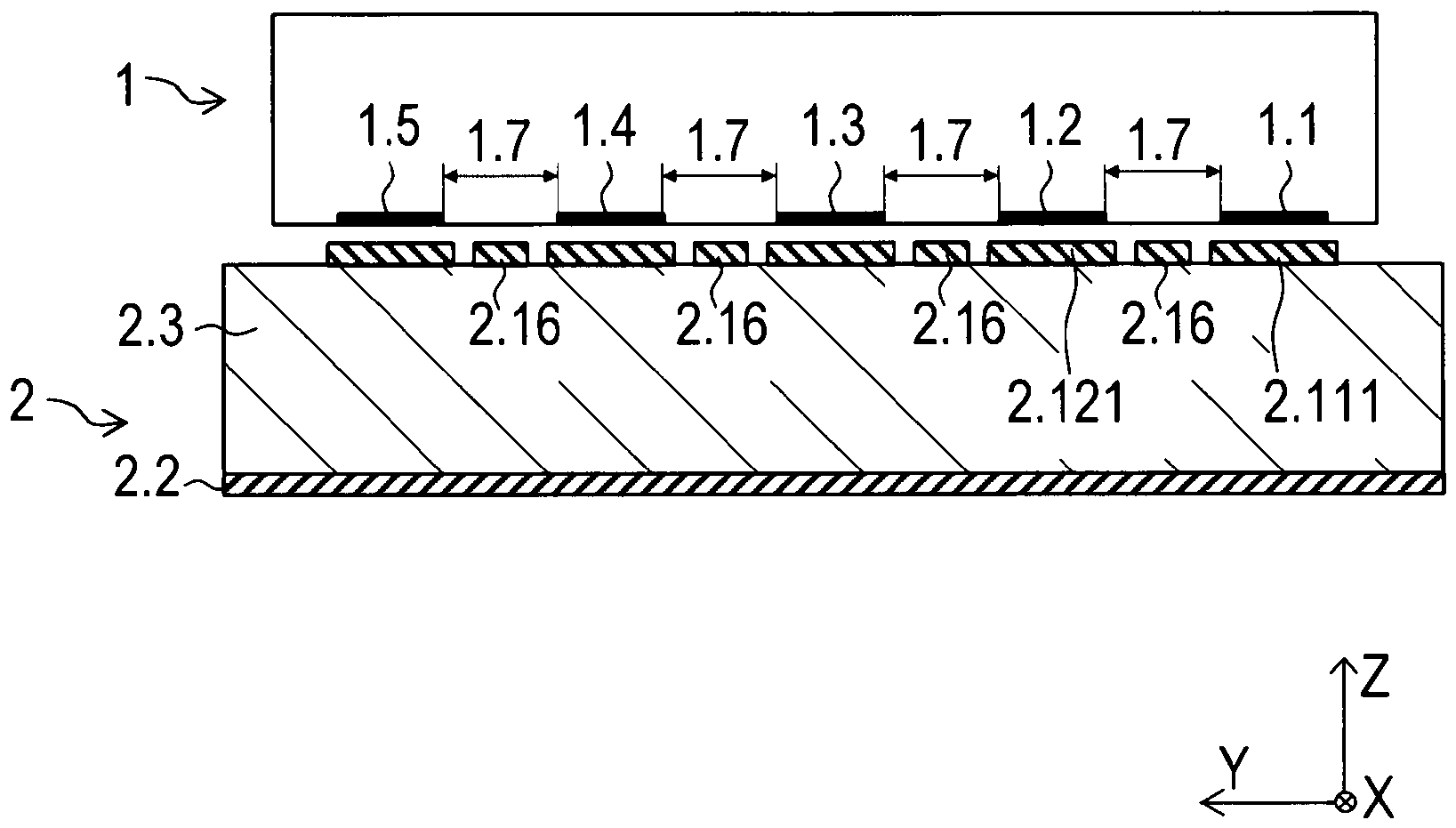
2 eine Schnittansicht des Skalenelements mit einem Abtastelement,2 a sectional view of the scale element with a scanning element, -
3 eine weitere Schnittansicht des Skalenelements,3 another sectional view of the scale element, -
4 eine Draufsicht auf das Skalenelement,4 a top view of the scale element, -
5 eine Draufsicht auf das Abtastelement,5 a top view of the scanning element, -
6 eine Draufsicht auf ein Detail des Abtastelements insbesondere auf die erste und zweite Empfängerspur und die Erregerleitung,6 a plan view of a detail of the scanning element, in particular of the first and second receiver tracks and the excitation line, -
7 eine Ansicht in Messrichtung auf die Positionsmesseinrichtung.7 a view in the measuring direction of the position measuring device.
BESCHREIBUNG DER AUSFÜHRUNGSFORMENDESCRIPTION OF THE EMBODIMENTS
Die Erfindung wird anhand einer Positionsmesseinrichtung beschrieben, welche zur Erfassung einer absoluten Relativposition zwischen einem entlang einer ersten Richtung X (Messrichtung) bewegbaren Abtastelement 1 (siehe
Das Skalenelement 2 wird im vorgestellten Ausführungsbeispiel aus einem mehrschichtigen Halbzeug hergestellt, wie es in der
Das oben genannte Halbzeug, beziehungsweise der Rohling für das Skalenelement 2 umfasst weiterhin auf einer Seite der Trägerschicht 2.3 eine Teilungsschicht 2.1 und auf der gegenüber liegenden Seite der Trägerschicht 2.3 eine Kompensationsschicht 2.2. Die Teilungsschicht 2.1 und die Kompensationsschicht 2.2 sind jeweils aus dem gleichen zweiten Material hergestellt, beispielsweise Aluminium oder Kupfer (spezifischer elektrischer Widerstand Al: 0,027 Ω mm2/m, Cu: 0,017 Ω mm2/m) und weisen jeweils die gleiche Stärke beziehungsweise Ausdehnung T21 in einer dritten Richtung Z auf, hier 24 µm. Es sind also sowohl die Teilungsschicht 2.1 als auch die Trägerschicht 2.3 wie auch die Kompensationsschicht 2.2 elektrisch leitfähig, zudem sind die Teilungsschicht 2.1 und die Trägerschicht 2.3 sowie die Kompensationsschicht 2.2 und die Trägerschicht 2.3 unmittelbar in Kontakt miteinander, so dass diese elektrisch leitend verbunden sind.The above-mentioned semi-finished product, or the blank for the
Im Zuge der Herstellung des Skalenelements 2 wird die Teilungsschicht 2.1, die unmittelbar auf der Trägerschicht 2.3 angeordnet ist, mit Hilfe eines Laserablationsprozesses strukturiert. Dabei wird die Teilungsschicht 2.1 stellenweise durch einen Laserstrahl über die gesamte Stärke T21 abgetragen. In der Folge entstehen dann unter anderem eine erste Teilungsspur 2.11, eine zweite Teilungsspur 2.12, eine dritte Teilungsspur 2.13, eine vierte Teilungsspur 2.14 und eine fünfte Teilungsspur 2.15 (siehe die
Die Ausbildung der Teilungsspuren 2.11 bis 2.15 wird im Folgenden anhand der ersten Teilungsspur 2.11 und der zweiten Teilungsspur 2.12 genauer beschrieben. Die erste Teilungsspur 2.11 und die zweite Teilungsspur 2.12 sind gemäß der
Weiterhin wird bei der Strukturierung der Teilungsschicht 2.1 im Zuge der Laserablation ein so genannter Abschirmsteg 2.16 erzeugt beziehungsweise stehen gelassen. Dieser Abschirmsteg 2.16 ist bezogen auf die zweite Richtung Y zwischen der ersten Teilungsspur 2.11 und der zweiten Teilungsspur 2.12 angeordnet und verläuft entlang der ersten Richtung X. Die Länge des Abschirmstegs 2.16 in der ersten Richtung X ist wesentlich größer als die erste Periodenlänge P11 oder die zweite Periodenlänge P12.Furthermore, during the structuring of the division layer 2.1 during laser ablation, a so-called shielding ridge 2.16 is created or left standing. This shielding ridge 2.16 is arranged between the first division track 2.11 and the second division track 2.12 with respect to the second direction Y and runs along the first direction X. The length of the shielding ridge 2.16 in the first direction X is significantly greater than the first period length P11 or the second period length P12.
Die Stege 2.111, 2.121 und der Abschirmsteg 2.16 sind aus demselben zweiten Material und elektrisch leitend. Das erste Material der Trägerschicht 2.3 ist auch elektrisch leitend. Zwischen der Trägerschicht 2.3 und den Stegen 2.111, 2.121 ist daher ein Stromfluss möglich, ebenso zwischen der Trägerschicht 2.3 und dem Abschirmsteg 2.16.The webs 2.111, 2.121 and the shielding web 2.16 are made of the same second material and are electrically conductive. The first material of the carrier layer 2.3 is also electrically conductive. Therefore, a current flow is possible between the carrier layer 2.3 and the webs 2.111, 2.121, as well as between the carrier layer 2.3 and the shielding web 2.16.
Analog sind auch die dritte bis fünfte Teilungsspur 2.13 bis 2.15 ausgestaltet, zwischen denen dann jeweils weitere Abschirmstege 2.16 angeordnet sind. Die Abschirmstege 2.16 weisen allesamt die gleiche Dicke beziehungsweise Ausdehnung T21 in der dritten Richtung Z auf, wie auch die Stege 2.111, 2.121 der ersten und zweiten Teilungsspur 2.11, 2.12. Gleiches gilt für die dritten bis fünften Teilungsspuren 2.13 bis 2.15. Auf diese Weise wird ein Skalenelement 2 hergestellt, das in der Draufsicht in der
Die Trägerschicht 2.3 ist bezogen auf die dritte Richtung Z zwischen den Teilungsspuren 2.11, 2.12 und der Kompensationsschicht 2.2 angeordnet. Die Kompensationsschicht 2.2 dient im Wesentlichen dazu, eine hohe Formstabilität und eine gute Ebenheit des Skalenelements 2 zu gewährleisten.The carrier layer 2.3 is arranged between the graduation tracks 2.11, 2.12 and the compensation layer 2.2 relative to the third direction Z. The compensation layer 2.2 essentially serves to ensure high dimensional stability and good flatness of the
In der
Zur Bestimmung der Relativposition zwischen dem Skalenelement 2 und dem Abtastelement 1 weist das Abtastelement 1 eine erste Empfängerspur 1.1, eine zweite Empfängerspur 1.2, eine dritte Empfängerspur 1.3, eine vierte Empfängerspur 1.4 und eine fünfte Empfängerspur 1.5 auf. Die Empfängerspuren 1.1 bis1.5 sind von einer Erregerleitung 1.6 umschlossen.To determine the relative position between the
Wie aus der
In der
Die erste Empfängerspur 1.1 und die zweite Empfängerspur 1.2 umfassen also im vorgestellten Ausführungsbeispiel jeweils zwei Empfängerleitungen 1.11, 1.12, 1.21, 1.22, die jeweils in der ersten Richtung X versetzt angeordnet sind, so dass diese dem Versatz entsprechend jeweils zwei phasenverschobene Signale liefern können. Die Empfängerleitungen 1.11, 1.12, 1.21, 1.22 sind hier als Leiterbahnen ausgestaltet und verlaufen mit Vias verbunden in unterschiedlichen Lagen der Leiterplatte beziehungsweise des Abtastelements 1, so dass an Kreuzungspunkten unerwünschte Kurzschlüsse vermieden werden. Wenngleich genau genommen jede der Empfängerleitungen 1.11, 1.12, 1.21, 1.22 aus vielen Leiterstücken besteht, die jeweils auf mehreren verschiedenen Ebenen beziehungsweise Lagen verteilt und aneinandergereiht sind, wird im Folgenden eine derartige Struktur zusammenfassend jeweils als eine Empfängerleitung 1.11, 1.12, 1.21, 1.22 bezeichnet.In the presented embodiment, the first receiver track 1.1 and the second receiver track 1.2 each comprise two receiver lines 1.11, 1.12, 1.21, 1.22, each offset in the first direction X, so that they can each deliver two phase-shifted signals according to the offset. The receiver lines 1.11, 1.12, 1.21, 1.22 are configured as conductor tracks and, connected by vias, run in different layers of the circuit board or the
Die erste Empfängerleitung 1.11 verläuft gemäß einem ersten periodischen Muster entlang der ersten Richtung X und die zweite Empfängerleitung 1.12 gemäß einem zweiten periodischen Muster. Die Empfängerleitungen 1.11, 1.12, 1.21, 1.22 weisen insbesondere einen räumlich periodischen Verlauf auf, der im Wesentlichen sinusförmig beziehungsweise sinusartig ausgestaltet ist, wobei alle Empfängerleitungen 1.11, 1.12 der ersten Empfängerspur 1.1 eine erste Periodenlänge P11 (
Im vorgestellten Ausführungsbeispiel sind innerhalb der ersten Empfängerspur 1.1 die Empfängerleitungen 1.11, 1.12 um ¼ der ersten Periodenlänge P11 entlang der ersten Richtung X zueinander versetzt angeordnet. Die Empfängerleitungen 1.11, 1.12 sind elektrisch so verschaltet, dass diese 0° und 90°-Signale liefern, aus denen ein erstes Positionssignal bestimmt werden kann. Durch die ersten Empfängerleitungen 1.11, 1.12 kann im Grunde ein vergleichsweise hochauflösendes Inkrementalsignal bei einer Relativbewegung des Skalenelements 2 gegenüber dem Abtastelement 1 erzeugt werden.In the presented embodiment, the receiver lines 1.11, 1.12 are arranged within the first receiver track 1.1, offset from one another by 1/4 of the first period length P11 along the first direction X. The receiver lines 1.11, 1.12 are electrically interconnected to deliver 0° and 90° signals from which a first position signal can be determined. The first receiver lines 1.11, 1.12 can essentially generate a comparatively high-resolution incremental signal upon a relative movement of the
Die zweite Empfängerspur 1.2 umfasst im vorgestellten Ausführungsbeispiel gemäß der
Im Übrigen gilt, dass auf dem Abtastelement 1 die erste Periodenlänge P11 die kleinste Periodenlänge ist, welche genauso groß ist wie die Periodenlänge der fünften Empfängerspur 1.5. Die mittlere dritte Empfängerspur 1.3 weist eine Periodenlänge auf, die geringfügig größer ist als die erste Periodenlänge P11. Die zweite Periodenlänge P12 wie auch die Periodenlänge der vierten Empfängerspur 1.4 sind größer als die erste Periodenlänge P11 und größer als die Periodenlänge der dritten Empfängerspur 1.3. Die gleiche Betrachtung bezüglich der Periodenlängen gilt analog auch für die Teilungsspuren 2.11 bis 2.15 des Skalenelements 2.Furthermore, on scanning
Im zusammengebauten Zustand der Positionsmesseinrichtung gemäß der
Wird die Erregerleitung 1.6 bestromt, so bildet sich um die Erregerleitung 1.6 ein schlauch- bzw. zylinderförmig orientiertes elektromagnetisches Feld aus. Die Feldlinien des resultierenden elektromagnetischen Feldes verlaufen um die Erregerleitung 1.6, wobei die Richtung der Feldlinien in bekannter Art und Weise von der Stromrichtung in der Erregerleitung 1.6 abhängt. Im Bereich der Stege 2.111, 2.121 werden Wirbelströme induziert, so dass jeweils eine von der Relativposition abhängige Modulation des Feldes erreicht wird. Entsprechend kann durch die Empfängerleitungen 1.11, 1.12, 1.21, 1.22 jeweils die Relativposition gemessen werden.When current is applied to excitation line 1.6, a tubular or cylindrical electromagnetic field forms around excitation line 1.6. The field lines of the resulting electromagnetic field run around excitation line 1.6, with the direction of the field lines depending, as is known, on the current direction in excitation line 1.6. Eddy currents are induced in the area of webs 2.111, 2.121, resulting in a modulation of the field dependent on the relative position. Accordingly, the relative position can be measured by receiver lines 1.11, 1.12, 1.21, and 1.22.
Alle Empfängerleitungen 1.11, 1.12 der ersten Empfängerspur 1.1 weisen jeweils die gleiche erste Periodenlänge P11 auf und die Empfängerleitungen 1.21, 1.22 der zweiten Empfängerspur 1.2 weisen jeweils die gleiche zweite Periodenlänge P12 auf. Die Abtastung beider Empfängerspuren 1.1, 1.2 erfolgt gleichzeitig, es ist keine Umschaltung zwischen einzelnen Empfängerspuren 1.1, 1.2 erforderlich. Beim Überstreichen eines Steges 2.111, 2.121 und einer Lücke 2.112, 2.122 wird durch das Abtastelement 1 eine Signalperiode erzeugt. Die erste Empfängerspur 1.1 mit ihren Empfängerleitungen 1.11, 1.12, die mit einer kleineren ersten Periodenlänge P11 verlaufen, tastet das Skalenelement 2 ab, so dass durch die erste Empfängerspur 1.1 eine vergleichsweise feine Bestimmung der Relativposition erreichbar ist. Gleichzeitig tastet die benachbarte zweite Empfängerspur 1.2 mit ihren Empfängerleitungen 1.21, 1.22, die mit einer gröberen zweiten Periodenlänge P12 verlaufen, das Skalenelement 2 ab. Durch die zweite Empfängerspur 1.2 ist somit eine vergleichsweise gröbere Bestimmung der Relativposition erreichbar. All receiver lines 1.11, 1.12 of the first receiver track 1.1 each have the same first period length P11, and the receiver lines 1.21, 1.22 of the second receiver track 1.2 each have the same second period length P12. Both receiver tracks 1.1, 1.2 are scanned simultaneously; no switching between individual receiver tracks 1.1, 1.2 is necessary. When scanning over a ridge 2.111, 2.121 and a gap 2.112, 2.122, a signal period is generated by the
Ebenso werden Signale in der dritten, vierten und fünften Empfängerspur 1.3 bis 1.5 bei der Abtastung der dritten, vierten und fünften Teilungsspur 2.13 bis 2.15 erzeugt beziehungsweise empfangen.Likewise, signals are generated or received in the third, fourth and fifth receiver tracks 1.3 to 1.5 during the scanning of the third, fourth and fifth division tracks 2.13 to 2.15.
Die empfangenen Signale werden mit Hilfe eines Schwebungs- beziehungsweise Noniusalgorithmus verknüpft, so dass durch die Signale die Relativposition zwischen dem Abtastelement 1 und dem Skalenelement 2 absolut bestimmt werden kann.The received signals are linked using a beat or vernier algorithm so that the relative position between the
Das Vorsehen von fünf Teilungsspuren 2.11 bis 2.15 und fünf Empfängerspuren 1.1 bis 1.5 hat unter anderem den Vorteil, dass die Messung vergleichsweise unempfindlich gegenüber einer Verdrehung des Skalenelements 2 relativ zum Abtastelement 1 ist (Minimierung des Moirè-Fehlers).The provision of five graduation tracks 2.11 to 2.15 and five receiver tracks 1.1 to 1.5 has, among other things, the advantage that the measurement is comparatively insensitive to a rotation of the
In unmittelbar benachbarten Empfängerspuren 1.1, 1.2 würde bei der hier vorgestellten Gestaltung der Teilungsspuren 2.11, 2.12 ein Übersprechsignal entstehen, das typischerweise eine Sinusform mit einer Übersprechperiodenlänge von circa fünfzehn zweiten Periodenlängen P12 oder sechzehn ersten Periodenlängen P11 aufweist. Die Längen der Empfängerleitungen 1.21, 1.22 in der ersten Richtung X entsprechen in etwa dieser Übersprechperiodenlänge. Diese Dimensionierung kann dazu beitragen, dass ein Übersprechen beim Abtasten unmittelbar benachbarter Teilungsspuren 2.11, 2.12 von vornherein in gewissen Grenzen reduziert ist. Es hat sich gezeigt, dass sich trotzdem bei der Verwendung herkömmlicher Skalenelemente mit einer elektrisch leitfähigen Teilung auf einem elektrisch leitfähigen Substrat Übersprecheffekte feststellbar sind. Durch die Erfindung ist es möglich das Übersprechen signifikant zu minimieren und damit die Messgenauigkeit zu optimieren.In immediately adjacent receiver tracks 1.1, 1.2, with the design of the graduation tracks 2.11, 2.12 presented here, a crosstalk signal would arise that typically has a sinusoidal shape with a crosstalk period length of approximately fifteen second period lengths P12 or sixteen first period lengths P11. The lengths of the receiver lines 1.21, 1.22 in the first direction X correspond approximately to this crosstalk period length. This dimensioning can contribute to reducing crosstalk when scanning immediately adjacent graduation tracks 2.11, 2.12 within certain limits. It has been shown that crosstalk effects can still be detected even when using conventional scale elements with an electrically conductive graduation on an electrically conductive substrate. The invention makes it possible to significantly minimize crosstalk and thus optimize measurement accuracy.
ZITATE ENTHALTEN IN DER BESCHREIBUNGQUOTES CONTAINED IN THE DESCRIPTION
Diese Liste der vom Anmelder aufgeführten Dokumente wurde automatisiert erzeugt und ist ausschließlich zur besseren Information des Lesers aufgenommen. Die Liste ist nicht Bestandteil der deutschen Patent- bzw. Gebrauchsmusteranmeldung. Das DPMA übernimmt keinerlei Haftung für etwaige Fehler oder Auslassungen.This list of documents submitted by the applicant was generated automatically and is included solely for the convenience of the reader. This list is not part of the German patent or utility model application. The DPMA assumes no liability for any errors or omissions.
Zitierte PatentliteraturCited patent literature
-
EP 2 515 086 A2 [0004]
EP 2 515 086 A2 [0004]
Claims (12)
Applications Claiming Priority (2)
| Application Number | Priority Date | Filing Date | Title |
|---|---|---|---|
| EP23214815.5 | 2023-12-07 | ||
| EP23214815.5A EP4567381A1 (en) | 2023-12-07 | 2023-12-07 | Inductive position measuring device |
Publications (1)
| Publication Number | Publication Date |
|---|---|
| DE102024003858A1 true DE102024003858A1 (en) | 2025-06-12 |
Family
ID=89121587
Family Applications (1)
| Application Number | Title | Priority Date | Filing Date |
|---|---|---|---|
| DE102024003858.2A Pending DE102024003858A1 (en) | 2023-12-07 | 2024-11-22 | INDUCTIVE POSITION MEASURING DEVICE |
Country Status (5)
| Country | Link |
|---|---|
| US (1) | US20250189348A1 (en) |
| EP (1) | EP4567381A1 (en) |
| JP (1) | JP2025092447A (en) |
| CN (1) | CN120120948A (en) |
| DE (1) | DE102024003858A1 (en) |
Family Cites Families (4)
| Publication number | Priority date | Publication date | Assignee | Title |
|---|---|---|---|---|
| DE102011007756A1 (en) | 2011-04-20 | 2012-10-25 | Dr. Johannes Heidenhain Gmbh | Position measuring device and scale and method for producing a scale |
| DE102012223037A1 (en) * | 2012-12-13 | 2014-06-18 | Dr. Johannes Heidenhain Gmbh | Inductive position measuring device |
| US11703359B2 (en) * | 2019-05-14 | 2023-07-18 | Kyocera Avx Components (Werne) Gmbh | Inductive position sensing apparatus including a screening layer and method for the same |
| ES2994002T3 (en) * | 2022-05-19 | 2025-01-16 | Heidenhain Gmbh Dr Johannes | Inductive position measurement device |
-
2023
- 2023-12-07 EP EP23214815.5A patent/EP4567381A1/en active Pending
-
2024
- 2024-11-22 DE DE102024003858.2A patent/DE102024003858A1/en active Pending
- 2024-11-28 JP JP2024206928A patent/JP2025092447A/en active Pending
- 2024-12-05 CN CN202411781725.9A patent/CN120120948A/en active Pending
- 2024-12-05 US US18/969,848 patent/US20250189348A1/en active Pending
Also Published As
| Publication number | Publication date |
|---|---|
| US20250189348A1 (en) | 2025-06-12 |
| EP4567381A1 (en) | 2025-06-11 |
| JP2025092447A (en) | 2025-06-19 |
| CN120120948A (en) | 2025-06-10 |
Similar Documents
| Publication | Publication Date | Title |
|---|---|---|
| EP1462770B1 (en) | Offset compensated Hall-sensor | |
| DE69626538T2 (en) | LOCATOR | |
| DE69201477T2 (en) | Capacitive position detector. | |
| AT509101B1 (en) | INDUCTIVE MEASURING DEVICE FOR LENGTH AND ANGLE DETECTION | |
| DE102005030358B4 (en) | Electromagnetic induction position sensor | |
| EP3179214B1 (en) | Inductive position measurement device | |
| EP0493385B1 (en) | High-resolution coder | |
| EP4012351B1 (en) | Scanning element and inductive position measuring device with the same | |
| EP3961158B1 (en) | Scanning unit and inductive position measuring device with such a scanning unit | |
| DE102017222063A1 (en) | Inductive position measuring device | |
| DE102005052688A1 (en) | Magnetic field sensor with a measuring bridge with MR sensor | |
| DE10011176C2 (en) | Two-dimensional position sensor with magnetic resistance | |
| EP3901582B1 (en) | Inductive angle measuring device | |
| EP2869031B1 (en) | Position measuring device | |
| DE102009042940A1 (en) | Position measuring device with repeatedly crossing transmitter winding arrangement | |
| DE102024003858A1 (en) | INDUCTIVE POSITION MEASURING DEVICE | |
| EP3764054B1 (en) | Sensor arrangement for detecting a deflection of a wire electrode | |
| DE19701137B4 (en) | Length sensor chip, the level of which is opposite a scale level | |
| EP4279874B1 (en) | Inductive position measurement device | |
| EP4273507B1 (en) | Scanning element and inductive position measuring device with the same | |
| EP4421453B1 (en) | Scanning element for an inductive angular measurement device | |
| DE102020205398A1 (en) | Inductive position measuring device | |
| DE102024110653B3 (en) | Measuring system and method for characterizing a multilayer structure with layer-by-layer different ohmic properties, sensor module for a measuring system, manufacturing system for a multilayer structure with layer-by-layer different ohmic properties | |
| EP4336148B1 (en) | Scanning element and inductive position measuring device comprising said scanning element | |
| WO2015090848A1 (en) | Absolute position measuring device |