DE102023210206A1 - Blower for a fuel cell arrangement - Google Patents
Blower for a fuel cell arrangement Download PDFInfo
- Publication number
- DE102023210206A1 DE102023210206A1 DE102023210206.4A DE102023210206A DE102023210206A1 DE 102023210206 A1 DE102023210206 A1 DE 102023210206A1 DE 102023210206 A DE102023210206 A DE 102023210206A DE 102023210206 A1 DE102023210206 A1 DE 102023210206A1
- Authority
- DE
- Germany
- Prior art keywords
- wall
- blower
- annular channel
- flow
- fuel cell
- Prior art date
- Legal status (The legal status is an assumption and is not a legal conclusion. Google has not performed a legal analysis and makes no representation as to the accuracy of the status listed.)
- Pending
Links
- 239000000446 fuel Substances 0.000 title claims abstract description 50
- 239000000203 mixture Substances 0.000 claims abstract description 49
- 230000003134 recirculating effect Effects 0.000 claims abstract description 8
- 238000009434 installation Methods 0.000 claims description 9
- 238000004519 manufacturing process Methods 0.000 claims description 8
- 239000000654 additive Substances 0.000 claims description 4
- 230000000996 additive effect Effects 0.000 claims description 4
- 239000000463 material Substances 0.000 claims description 4
- 239000007769 metal material Substances 0.000 claims description 3
- 238000011144 upstream manufacturing Methods 0.000 claims description 2
- 239000007789 gas Substances 0.000 description 45
- XLYOFNOQVPJJNP-UHFFFAOYSA-N water Substances O XLYOFNOQVPJJNP-UHFFFAOYSA-N 0.000 description 32
- UFHFLCQGNIYNRP-UHFFFAOYSA-N Hydrogen Chemical compound [H][H] UFHFLCQGNIYNRP-UHFFFAOYSA-N 0.000 description 10
- 239000001257 hydrogen Substances 0.000 description 10
- 229910052739 hydrogen Inorganic materials 0.000 description 10
- 238000000926 separation method Methods 0.000 description 3
- 230000000694 effects Effects 0.000 description 2
- 238000001746 injection moulding Methods 0.000 description 2
- 239000007788 liquid Substances 0.000 description 2
- 238000005086 pumping Methods 0.000 description 2
- 238000010146 3D printing Methods 0.000 description 1
- 229910000838 Al alloy Inorganic materials 0.000 description 1
- 229910052782 aluminium Inorganic materials 0.000 description 1
- XAGFODPZIPBFFR-UHFFFAOYSA-N aluminium Chemical compound [Al] XAGFODPZIPBFFR-UHFFFAOYSA-N 0.000 description 1
- 230000015572 biosynthetic process Effects 0.000 description 1
- 230000007613 environmental effect Effects 0.000 description 1
- 239000012530 fluid Substances 0.000 description 1
- 229910052751 metal Inorganic materials 0.000 description 1
- 239000002184 metal Substances 0.000 description 1
- 238000000034 method Methods 0.000 description 1
- 238000010926 purge Methods 0.000 description 1
- 238000005096 rolling process Methods 0.000 description 1
- 238000007789 sealing Methods 0.000 description 1
Images


Classifications
-
- F—MECHANICAL ENGINEERING; LIGHTING; HEATING; WEAPONS; BLASTING
- F04—POSITIVE - DISPLACEMENT MACHINES FOR LIQUIDS; PUMPS FOR LIQUIDS OR ELASTIC FLUIDS
- F04D—NON-POSITIVE-DISPLACEMENT PUMPS
- F04D25/00—Pumping installations or systems
- F04D25/02—Units comprising pumps and their driving means
- F04D25/06—Units comprising pumps and their driving means the pump being electrically driven
- F04D25/0606—Units comprising pumps and their driving means the pump being electrically driven the electric motor being specially adapted for integration in the pump
-
- F—MECHANICAL ENGINEERING; LIGHTING; HEATING; WEAPONS; BLASTING
- F04—POSITIVE - DISPLACEMENT MACHINES FOR LIQUIDS; PUMPS FOR LIQUIDS OR ELASTIC FLUIDS
- F04D—NON-POSITIVE-DISPLACEMENT PUMPS
- F04D29/00—Details, component parts, or accessories
- F04D29/40—Casings; Connections of working fluid
- F04D29/42—Casings; Connections of working fluid for radial or helico-centrifugal pumps
- F04D29/4206—Casings; Connections of working fluid for radial or helico-centrifugal pumps especially adapted for elastic fluid pumps
- F04D29/4213—Casings; Connections of working fluid for radial or helico-centrifugal pumps especially adapted for elastic fluid pumps suction ports
-
- F—MECHANICAL ENGINEERING; LIGHTING; HEATING; WEAPONS; BLASTING
- F04—POSITIVE - DISPLACEMENT MACHINES FOR LIQUIDS; PUMPS FOR LIQUIDS OR ELASTIC FLUIDS
- F04D—NON-POSITIVE-DISPLACEMENT PUMPS
- F04D29/00—Details, component parts, or accessories
- F04D29/40—Casings; Connections of working fluid
- F04D29/42—Casings; Connections of working fluid for radial or helico-centrifugal pumps
- F04D29/44—Fluid-guiding means, e.g. diffusers
- F04D29/441—Fluid-guiding means, e.g. diffusers especially adapted for elastic fluid pumps
- F04D29/444—Bladed diffusers
-
- F—MECHANICAL ENGINEERING; LIGHTING; HEATING; WEAPONS; BLASTING
- F04—POSITIVE - DISPLACEMENT MACHINES FOR LIQUIDS; PUMPS FOR LIQUIDS OR ELASTIC FLUIDS
- F04D—NON-POSITIVE-DISPLACEMENT PUMPS
- F04D25/00—Pumping installations or systems
- F04D25/02—Units comprising pumps and their driving means
- F04D25/06—Units comprising pumps and their driving means the pump being electrically driven
- F04D25/0606—Units comprising pumps and their driving means the pump being electrically driven the electric motor being specially adapted for integration in the pump
- F04D25/066—Linear Motors
-
- F—MECHANICAL ENGINEERING; LIGHTING; HEATING; WEAPONS; BLASTING
- F05—INDEXING SCHEMES RELATING TO ENGINES OR PUMPS IN VARIOUS SUBCLASSES OF CLASSES F01-F04
- F05D—INDEXING SCHEME FOR ASPECTS RELATING TO NON-POSITIVE-DISPLACEMENT MACHINES OR ENGINES, GAS-TURBINES OR JET-PROPULSION PLANTS
- F05D2250/00—Geometry
- F05D2250/50—Inlet or outlet
- F05D2250/51—Inlet
Landscapes
- Engineering & Computer Science (AREA)
- Mechanical Engineering (AREA)
- General Engineering & Computer Science (AREA)
- Structures Of Non-Positive Displacement Pumps (AREA)
Abstract
Ein Gebläse (1) für eine Brennstoffzellenanordnung zur Rezirkulation eines für den Betrieb der Brennstoffzellenanordnung eingesetzten Gasgemischs ist mit einem Antriebsmotor (7, 8, 9) versehen, der einen mit einer Motorwelle (7) gekoppelten Rotor (9) und einen radial außerhalb des Rotors (9) angeordneten Stator (8) aufweist. Radial zwischen dem Rotor (9) und dem Stator (8) ist ein Ringkanal (10) zur Leitung des Gasgemischs von einer Eintrittsseite zu einer Austrittsseite des Ringkanals (10) vorgesehen, wobei im Bereich der Austrittsseite des Ringkanals (10) ein mit der Motorwelle (7) gekoppeltes Gebläselaufrad (5) vorgesehen ist, um bei Rotation das Gasgemisch von der Eintrittsseite zu der Austrittseite des Ringkanals (10) zu fördern. Ferner ist eine Strömungsleiteinrichtung (14) vorgesehen, um auf das in den Ringkanal (10) eintretende Gasgemisch einen Drall in Umfangsrichtung des Ringkanals (10) aufzuprägen. Der Ringkanal (10) wird mit einer Baugruppe aus einer Außenwand (16; 21) und einer Innenwand (17) begrenzt, wobei die Strömungsleiteinrichtung (14) an der Eintrittsseite zwischen der Außenwand (16; 21) und der Innenwand (17) vorgesehen ist.
Description
Technisches GebietTechnical area
Die vorliegende Erfindung bezieht sich auf ein Gebläse für eine Brennstoffzellenanordnung zur Rezirkulation eines für den Betrieb der Brennstoffzellenanordnung eingesetzten Gasgemischs. Insbesondere bezieht sich die vorliegende Erfindung auf ein Gebläse, mit dem eine Abscheidung von Wasser aus dem Gasgemisch ermöglicht wird. Außerdem betrifft die Erfindung eine Brennstoffzellenanordnung mit einem derartigen Gebläse.The present invention relates to a blower for a fuel cell assembly for recirculating a gas mixture used for operating the fuel cell assembly. In particular, the present invention relates to a blower that enables the separation of water from the gas mixture. Furthermore, the invention relates to a fuel cell assembly with such a blower.
Stand der TechnikState of the art
Brennstoffzellen verschiedener Bauarten werden für stationäre und mobile Anwendungen eingesetzt. Bei derartigen bekannten Brennstoffzellen, bei denen Wasserstoff als Energieträger eingesetzt wird, besteht der Bedarf, gasförmige Medien zu fördern. Insbesondere sind Brennstoffzellen mit einem Anodenbereich und einem Kathodenbereich bekannt, wobei Wasserstoff aus dem Anodenbereich rezirkuliert wird, um die Funktion der Brennstoffzelle zu gewährleisten. Hierzu werden im Stand der Technik Gebläse eingesetzt, die zur Förderung des entsprechenden gasförmigen Mediums eingerichtet sind.Fuel cells of various designs are used for stationary and mobile applications. In such known fuel cells, which use hydrogen as the energy carrier, there is a need to convey gaseous media. In particular, fuel cells with an anode region and a cathode region are known, with hydrogen being recirculated from the anode region to ensure the function of the fuel cell. For this purpose, fans designed to convey the corresponding gaseous medium are used in the prior art.
Es ist die Aufgabe der Erfindung, ein verbessertes und einfach herstellbares Gebläse zur Verfügung zu stellen, mit dem die Funktion des Brennstoffzellensystems sichergestellt werden kann. Die Aufgabe wird mit den Merkmalen der Ansprüche gelöst.The object of the invention is to provide an improved and easily manufactured blower that can ensure the proper functioning of the fuel cell system. This object is achieved by the features of the claims.
Darstellung der ErfindungDescription of the invention
Die vorliegende Erfindung betrifft gemäß einem Aspekt ein Gebläse für eine Brennstoffzellenanordnung. Das Gebläse für eine Brennstoffzellenanordnung ist zur Rezirkulation eines für den Betrieb der Brennstoffzellenanordnung eingesetzten Gasgemischs vorgesehen. Das Gebläse weist einen Antriebsmotor auf, der einen mit einer Motorwelle gekoppelten Rotor und einen radial außerhalb des Rotors angeordneten Stator aufweist. According to one aspect, the present invention relates to a blower for a fuel cell assembly. The blower for a fuel cell assembly is provided for recirculating a gas mixture used to operate the fuel cell assembly. The blower has a drive motor that has a rotor coupled to a motor shaft and a stator arranged radially outside the rotor.
Dabei ist radial zwischen dem Rotor und dem Stator ein Ringkanal zur Leitung des Gasgemischs von einer Eintrittsseite zu einer Austrittsseite des Ringkanals vorgesehen, wobei im Bereich der Austrittsseite des Ringkanals ein mit der Motorwelle gekoppeltes Gebläselaufrad vorgesehen ist, um bei Rotation das Gasgemisch von der Eintrittsseite zu der Austrittsseite des Ringkanals zu fördern.In this case, an annular channel is provided radially between the rotor and the stator for conducting the gas mixture from an inlet side to an outlet side of the annular channel, wherein in the region of the outlet side of the annular channel a fan impeller coupled to the motor shaft is provided in order to convey the gas mixture from the inlet side to the outlet side of the annular channel during rotation.
Das Gebläse weist ferner eine Strömungsleiteinrichtung auf, die im Bereich der Eintrittsseite des Ringkanals vorgesehen und eingerichtet ist, um auf das in den Ringkanal eintretende Gasgemisch einen Drall in Umfangsrichtung des Ringkanals aufzuprägen.The blower further comprises a flow guide device which is provided in the region of the inlet side of the annular channel and is designed to impart a swirl in the circumferential direction of the annular channel to the gas mixture entering the annular channel.
Bei dem Gebläse ist der Ringkanal mit einer Baugruppe aus einer Außenwand und einer Innenwand begrenzt, wobei die Strömungsleiteinrichtung an der Eintrittsseite zwischen der Außenwand und der Innenwand vorgesehen ist.In the blower, the annular duct is defined by an assembly consisting of an outer wall and an inner wall, with the flow guide device being provided on the inlet side between the outer wall and the inner wall.
Das Gebläse kann zur Rezirkulation eines Gasgemischs eingesetzt werden, das einem Anodenbereich der Brennstoffzellenanordnung zugeordnet ist. Das Gasgemisch kann Wasserstoff enthalten. Das Gasgemisch kann ferner weitere Komponenten enthalten, die sich insbesondere aus der Reaktion des Wasserstoffs im Anodenbereich der Brennstoffzellenanordnung ergeben können. Das Gasgemisch kann Wasser enthalten, das sich aus der Reaktion des Wasserstoffs ergibt. Das Gasgemisch kann durch den Anodenbereich der Brennstoffzellenanordnung hindurchgeführt werden.The blower can be used to recirculate a gas mixture associated with an anode region of the fuel cell assembly. The gas mixture can contain hydrogen. The gas mixture can also contain other components that can result, in particular, from the reaction of the hydrogen in the anode region of the fuel cell assembly. The gas mixture can contain water, which results from the reaction of the hydrogen. The gas mixture can be passed through the anode region of the fuel cell assembly.
Das Gebläse kann über entsprechende Rohrleitungen innerhalb der Brennstoffzellenanordnung mit einem oder mehreren Brennstoffzellenmodulen so verbunden sein, dass das Gebläse das Gasgemisch durch den Anodenbereich der Brennstoffzellenanordnung leiten kann. Das Gebläse kann ferner mit einer Wasserstoffquelle verbunden sein, über die das rezirkulierte Gasgemisch hinsichtlich des Wasserstoffgehalts eingestellt werden kann. Das Gebläse kann mit einem Antriebsmotor betrieben werden, der als Elektromotor ausgestaltet sein kann. Der Elektromotor kann als bürstenloser Motor ausgebildet sein. Der Antriebsmotor kann als Medienspaltmotor ausgebildet sein. In diesem Fall kann das von dem Gebläse geförderte Medium, insbesondere das bei der Brennstoffzellenanordnung eingesetzte Gasgemisch, durch den Ringkanal gefördert werden. Der Ringkanal kann dabei eine zylindrische Innenwand und eine zylindrische Außenwand aufweisen. Zwischen der zylindrischen Innenwand und der zylindrischen Außenwand des Ringkanals kann das Gasgemisch von der Eintrittsseite zu der Austrittsseite strömen. Die zylindrische Außenwand kann dabei zumindest abschnittsweise als äußeres Rohr ausgebildet sein, das radial innerhalb des Stators angeordnet ist. Die zylindrische Innenwand kann zumindest abschnittsweise durch einen Außenumfang des Rotors gebildet sein. Die zylindrische Innenwand kann alternativ zumindest abschnittsweise durch ein inneres Rohr gebildet sein, das radial außerhalb des Rotors angeordnet ist.The blower can be connected to one or more fuel cell modules via appropriate piping within the fuel cell arrangement such that the blower can direct the gas mixture through the anode region of the fuel cell arrangement. The blower can also be connected to a hydrogen source, via which the hydrogen content of the recirculated gas mixture can be adjusted. The blower can be operated by a drive motor, which can be configured as an electric motor. The electric motor can be designed as a brushless motor. The drive motor can be designed as a media gap motor. In this case, the medium conveyed by the blower, in particular the gas mixture used in the fuel cell arrangement, can be conveyed through the annular channel. The annular channel can have a cylindrical inner wall and a cylindrical outer wall. The gas mixture can flow from the inlet side to the outlet side between the cylindrical inner wall and the cylindrical outer wall of the annular channel. The cylindrical outer wall can be designed, at least in sections, as an outer tube that is arranged radially inside the stator. The cylindrical inner wall may be formed, at least in part, by an outer periphery of the rotor. Alternatively, the cylindrical inner wall may be formed, at least in part, by an inner tube arranged radially outside the rotor.
Das mit der Motorwelle gekoppelte Gebläselaufrad kann an der Austrittsseite des Ringkanals derart vorgesehen sein, dass das Gasgemisch durch den Ringkanal bei Rotation des Gebläselaufrads gefördert werden kann. Das Gebläselaufrad kann eine Anordnung von Schaufeln aufweisen, die um den Umfang des Gebläselaufrads verteilt sind. Durch Rotation des Gebläselaufrads kann das Gasgemisch auf der Grundlage einer entsprechenden Pumpfunktion gefördert werden. Dabei kann das Gebläselaufrad das Gasgemisch aufgrund der Rotation in einer radialen Richtung bezogen auf den Ringkanal fördern.The fan impeller coupled to the motor shaft can be provided on the outlet side of the annular channel in such a way that the gas mixture is forced through the annular channel when the fan impeller rotates. The fan impeller can have an arrangement of blades distributed around the circumference of the fan impeller. Rotation of the fan impeller can convey the gas mixture based on a corresponding pumping function. Due to its rotation, the fan impeller can convey the gas mixture in a radial direction relative to the annular channel.
Die Strömungsleiteinrichtung kann im Bereich der Eintrittsseite des Ringkanals vorgesehen und derart eingerichtet sein, dass auf das in den Ringkanal eintretende Gasgemisch ein Drall in Umfangsrichtung des Ringkanals erzeugt wird, der das Gasgemisch um die Innenwand des Ringkanals herum bewegt. Insbesondere kann die Strömungsleiteinrichtung derart eingerichtet sein, dass das Gasgemisch entlang Stromlinien durch den Ringkanal bewegt wird, die eine Umfangsgeschwindigkeitskomponente aufweisen. Aufgrund der Überlagerung der Umfangsgeschwindigkeitskomponente mit einer Axialgeschwindigkeitskomponente kann das Gasgemisch mit einer Schraubenform um die Innenwand des Ringkanals gefördert werden. Insofern ist die Strömungsleiteinrichtung derart ausgebildet, dass ein Drall zur Ausbildung von schraubenförmigen Stromlinien des Gasgemischs um die Längsachse des Ringkanals erzeugt werden kann. Aufgrund des Dralls, der durch die Strömungsleiteinrichtung auf das geförderte Gasgemisch aufgeprägt wird, wird auf die Bestandteile des Gasgemischs eine Zentrifugalkraft aufgeprägt, die bewirkt, dass Bestandteile mit höherer Dichte des Gasgemischs sich innerhalb des Ringkanals radial nach außen bewegen.The flow guide device can be provided in the region of the inlet side of the annular channel and configured such that a swirl in the circumferential direction of the annular channel is generated on the gas mixture entering the annular channel, which swirl moves the gas mixture around the inner wall of the annular channel. In particular, the flow guide device can be configured such that the gas mixture is moved through the annular channel along streamlines that have a circumferential velocity component. Due to the superposition of the circumferential velocity component with an axial velocity component, the gas mixture can be conveyed in a helical shape around the inner wall of the annular channel. In this respect, the flow guide device is designed such that a swirl can be generated to form helical streamlines of the gas mixture around the longitudinal axis of the annular channel. Due to the swirl imposed on the conveyed gas mixture by the flow guide device, a centrifugal force is imposed on the components of the gas mixture, causing components with a higher density of the gas mixture to move radially outwards within the annular channel.
Gemäß einer Ausführungsform kann die Strömungsleiteinrichtung eine durchströmbare Anordnung von Leitschaufeln aufweisen, die sich zwischen der Außenwand und der Innenwand erstrecken.According to one embodiment, the flow guiding device may comprise a flow-through arrangement of guide vanes extending between the outer wall and the inner wall.
Gemäß einer Ausführungsform kann die die Strömungsleiteinrichtung einstückig mit zumindest einem von der Außenwand und der Innenwand ausgebildet sein. Hierzu können die Elemente der Strömungsleiteinrichtung gemeinsam mit den Ringkanal zumindest abschnittsweise begrenzenden rohrförmigen Elementen hergestellt werden. Die Elemente des Ringkanals können Leitschaufeln umfassen.According to one embodiment, the flow guide device can be formed integrally with at least one of the outer wall and the inner wall. For this purpose, the elements of the flow guide device can be manufactured together with tubular elements that delimit the annular channel at least in sections. The elements of the annular channel can comprise guide vanes.
Gemäß einer Ausführungsform können die Außenwand oder die Innenwand über die Strömungsleiteinrichtung zu einer Baugruppe verbunden sein. Alternativ können die Außenwand und die Innenwand über die Strömungsleiteinrichtung zu einer Baugruppe verbunden sein.According to one embodiment, the outer wall or the inner wall can be connected to form a single assembly via the flow-guiding device. Alternatively, the outer wall and the inner wall can be connected to form a single assembly via the flow-guiding device.
Gemäß einer Ausführungsform kann die an der stromaufwärtigen Seite der Strömungsleiteinrichtung ein Strömungseinbau vorgesehen sein, der eingerichtet ist, um eine auf den Strömungseinbau gerichtete Strömung über die Strömungsleiteinrichtung in den Ringkanal zu leiten. Der Strömungseinbau kann einstückig mit den Ringkanal begrenzenden rohrförmigen Elementen hergestellt werden. Der Strömungseinbau kann alternativ oder zusätzlich einstückig mit den Elementen der Strömungsleiteinrichtung hergestellt sein.According to one embodiment, a flow insert can be provided on the upstream side of the flow guide device, which is configured to guide a flow directed toward the flow insert via the flow guide device into the annular channel. The flow insert can be manufactured integrally with the tubular elements delimiting the annular channel. Alternatively or additionally, the flow insert can be manufactured integrally with the elements of the flow guide device.
Gemäß einer Ausführungsform kann der Strömungseinbau insbesondere einstückig zumindest mit der Außenwand ausgebildet sein.According to one embodiment, the flow installation can in particular be formed integrally at least with the outer wall.
Gemäß einer Ausführungsform können die Außenwand und die Innenwand über die Strömungsleiteinrichtung zu einer Baugruppe als ein Teil gefertigt sein. Hierzu kann ein Spitzgussverfahren eingesetzt werden. Alternativ kann zumindest ein Abschnitt der Baugruppe mit einem additiven Herstellungsverfahren hergestellt werden.According to one embodiment, the outer wall and the inner wall can be manufactured as a single part via the flow guide device to form an assembly. An injection molding process can be used for this purpose. Alternatively, at least a portion of the assembly can be manufactured using an additive manufacturing process.
Gemäß einer Ausführungsform kann die als ein Teil gefertigte Baugruppe den Strömungseinbau umfassen. In diesem Fall werden die den Ringkanal begrenzenden Elemente, die Leitschaufeln und der Strömungseinbau gemeinsam gefertigt.According to one embodiment, the assembly manufactured as a single part may include the flow insert. In this case, the elements defining the annular channel, the guide vanes, and the flow insert are manufactured together.
Gemäß einer Ausführungsform kann die Baugruppe aus Kunststoff gefertigt sein. Die Baugruppe kann aus Aliminium hergestellt sein.According to one embodiment, the assembly may be made of plastic. The assembly may be made of aluminum.
Gemäß einer Ausführungsform kann die Baugruppe mit einem additiven Fertigungsverfahren hergestellt ist. Dabei können auf einzelne Abschnitte der Baugruppe additiv gefertigt werden und zusätzlich weitere Herstellungsverfahren zum Einsatz kommen.According to one embodiment, the assembly can be manufactured using an additive manufacturing process. Individual sections of the assembly can be additively manufactured, and additional manufacturing processes can be used.
Gemäß einer Ausführungsform kann an der radial innen liegenden Seite der Innenwand ein Lagersitz für ein Lager zum Abstützen der Motorwelle vorgesehen sein. Das Lager kann in diesem Fall gegenüber dem inneren Rohr, das den Ringkanal begrenzt, und somit gegenüber dem Gehäuse des Gebläses abgestützt werden.According to one embodiment, a bearing seat for a bearing supporting the motor shaft can be provided on the radially inner side of the inner wall. In this case, the bearing can be supported relative to the inner tube defining the annular channel and thus relative to the fan housing.
Gemäß einer Ausführungsform kann ein Lagersitz für ein Lager zum Abstützen der Motorwelle an einem Innenumfang des Strömungseinbaus ausgebildet sein. Das Lager kann in diesem Fall gegenüber dem Gehäuse des Gebläses über der Strömungsleiteinrichtung abgestützt werden.According to one embodiment, a bearing seat for a bearing for supporting the motor shaft can be formed on an inner circumference of the flow assembly. In this case, the bearing can be supported relative to the fan housing above the flow guide device.
Gemäß einer Ausführungsform kann der Lagersitz aus einem Metallwerkstoff ausgebildeten und an das Material der Innenwand angeformt sein. Hierzu kann ein Ring als Lagersitz in oder an das Material der Innenwand angebracht sein. Dabei kann der Lagersitz bei der Herstellung der inneren Rohrs oder des Strömungseinbaus integriert werden.According to one embodiment, the bearing seat can be made of a metal material and molded onto the material of the inner wall. For this purpose, a ring can be attached as a bearing seat in or onto the material of the inner wall. the bearing seat can be integrated during the manufacture of the inner tube or the flow installation.
Gemäß einer Ausführungsform kann im Bereich der Austrittsseite des Ringkanals in eine Wasserabfuhranordnung münden, die zur Abfuhr von sich an der Wand der Aufweitung bewegendes Wassers zu einer Wasseraustrittsanordnung eingerichtet. Die Wasserabfuhranordnung kann als ringförmiger Kanal am Austrittsende ausgebildet sein, der mit einer Leitung zum Abführen des in den Ringkanal eintretenden Wassers verbunden sein kann. Die Wasserabfuhranordnung kann als mindestens eine Öffnung in oder an der Austrittsseite des Ringkanals ausgebildet sein, in das das Wasser eintreten kann. Die Wasseraustrittsanordnung kann einen Behälter zur Aufnahme des aus der Wasserabfuhranordnung abgeführten Wassers aufweisen. Die Wasseraustrittsanordnung kann ferner eine Leitung aufweisen, mit der das von der Wasserabfuhranordnung abgeführte Wasser abgeführt, insbesondere in die Umgebung abgelassen werden kann.According to one embodiment, in the region of the outlet side of the annular channel, a water drainage arrangement can open, which is configured to drain water moving along the wall of the widened portion to a water outlet arrangement. The water drainage arrangement can be designed as an annular channel at the outlet end, which can be connected to a line for draining the water entering the annular channel. The water drainage arrangement can be designed as at least one opening in or on the outlet side of the annular channel, into which the water can enter. The water outlet arrangement can have a container for receiving the water drained from the water drainage arrangement. The water outlet arrangement can further have a line by means of which the water drained by the water drainage arrangement can be drained away, in particular into the environment.
Gemäß einem weiteren Aspekt ist eine Brennstoffzellenanordnung mit einem Gebläse angegeben, das eines oder mehrere der vorstehend genannten Merkmale aufweist, wobei das Gebläse zur Rezirkulation eines für den Betrieb der Brennstoffzellenanordnung eingesetzten Gasgemischs mit der Brennstoffzellenanordnung verbunden ist. Dabei kann das Gebläse mit einer Leitungsanordnung in der Brennstoffzellenanordnung mit einem Brennstoffzellenmodul verbunden sein. Das Gebläse kann zum Rezirkulieren von Wasserstoff enthaltendem Gas für die Brennstoffzellenanordnung vorgesehen sein. Insbesondere kann die Rezirkulation des Wasserstoff enthaltenden Gases für die Anodenseite der Brennstoffzellenanordnung ausgebildet sein. Das Gebläse kann bedarfsweise über eine Steuerungseinrichtung gesteuert werden, wobei ein Betriebszustand der Brennstoffzellenanordnung berücksichtigt werden kann. Die Brennstoffzellenanordnung kann auch mehrere Gebläse der vorstehend beschriebenen Bauart aufweisen, die entsprechend mit Leitungen in die Brennstoffzellenanordnung eingebunden sind.According to a further aspect, a fuel cell arrangement is provided with a blower that has one or more of the features mentioned above, wherein the blower is connected to the fuel cell arrangement for recirculating a gas mixture used for operating the fuel cell arrangement. The blower can be connected to a fuel cell module via a line arrangement in the fuel cell arrangement. The blower can be provided for recirculating hydrogen-containing gas for the fuel cell arrangement. In particular, the recirculation of the hydrogen-containing gas can be designed for the anode side of the fuel cell arrangement. The blower can be controlled via a control device as needed, wherein an operating state of the fuel cell arrangement can be taken into account. The fuel cell arrangement can also have a plurality of blowers of the type described above, which are correspondingly integrated into the fuel cell arrangement via lines.
Das Gebläse und die Brennstoffzellenanordnung können in einer mobilen Anwendung eingesetzt werden. Insbesondere können das Gebläse und die Brennstoffzellenanordnung in einem elektrisch betriebenen Fahrzeug eingesetzt werden, wobei die elektrische Leistung von der Brennstoffzellenanordnung erzeugt werden kann. Alternativ kann die Brennstoffzellenanordnung mit dem Gebläse in einer stationären Anwendung eingesetzt werden. Das Gebläse kann alternativ zum Bereitstellen einer Gasströmung in anderen Bereichen eingesetzt werden. Insbesondere kann das Gebläse zur Erzielung einer Durchströmung der Kathodenseite der Brennstoffzellenanordnung eingesetzt werden.The blower and the fuel cell assembly can be used in a mobile application. In particular, the blower and the fuel cell assembly can be used in an electrically powered vehicle, wherein the electrical power can be generated by the fuel cell assembly. Alternatively, the fuel cell assembly with the blower can be used in a stationary application. Alternatively, the blower can be used to provide a gas flow in other areas. In particular, the blower can be used to achieve a flow through the cathode side of the fuel cell assembly.
Kurze Beschreibung der FigurenShort description of the characters
-
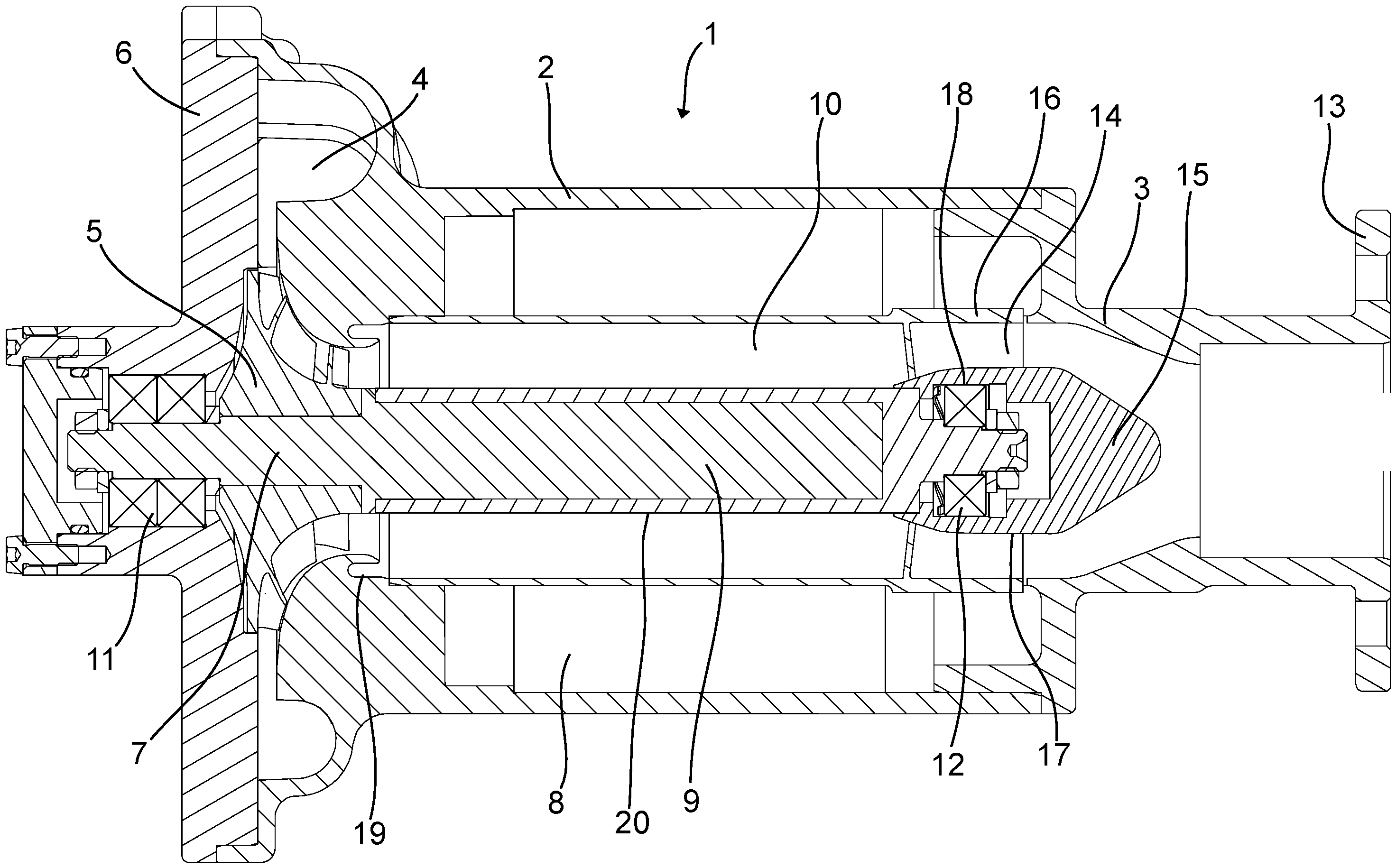
1 zeigt eine Ausführungsform eines Gebläses in einer Querschnittsansicht; und1 shows an embodiment of a fan in a cross-sectional view; and -
2 zeigt eine abgewandelte Ausführungsform eines Gebläses in einer Querschnittsansicht.2 shows a modified embodiment of a blower in a cross-sectional view.
Detaillierte Beschreibung von AusführungsformenDetailed description of embodiments
Im Folgenden werden Ausführungsformen unter Bezugnahme auf die beigefügten Zeichnungen beschrieben.Embodiments are described below with reference to the accompanying drawings.
An der linken Seite in
Das Gebläselaufrad 5 weist Schaufeln auf, die mit einer vorbestimmten Form zur Erzielung der Pumpfunktion ausgestaltet sind. Die Innenseite des Gehäuseflanschs 6 und die Innenseite des Austrittsgehäuses 4 sind im radialen Bereich, an dem das Gebläselaufrad 5 vorgesehen ist, an die Kontur des Gebläselaufrads 5 angepasst. Radial außerhalb des Gebläselaufrads 5 befindet sich ein Ringspalt, der zu der Volute innerhalb des Austrittsgehäuses 4 offen ist. An der dem Rotor 9 abgewandten Seite des Gebläselaufrads 5 ist das Lager 11 zum Abstützen der Motorwelle 7 vorgesehen. In der vorliegenden Ausführungsform umfasst das Lager 11 einen Satz Wälzlager, die mit dem Außenring in den Gehäuseflansch eingesetzt sind und die mit dem Innenring auf die Motorwelle 7 aufgesetzt sind. Der Gehäuseflansch 6 weist an der bezüglich des Rotors abgewandten Seite des Lagers 11 einen nicht näher erläuterten Deckel auf.The
Radial zwischen dem Stator 8 und dem Rotor 9 ist ein Ringkanal 10 vorgesehen. Eine radiale Innenwand 17 des Ringkanals 10 wird durch einen Außenumfang 20 des Rotors 9 und durch einen Außenumfang eines Strömungseinbaus 15 gebildet. In einer alternativen Ausführungsform wird die radiale Innenwand durch ein inneres Rohr, das den Rotor 9 umgibt, und durch den Außenumfang des Strömungseinbaus 15 gebildet. An der bezüglich des Rotors 9 abgewandten Seite des Leitgitters 14 ist der Strömungseinbau 15 in der Form eines achssymmetrischen Strömungskörpers vorgesehen. Der Strömungseinbau 15 weist eine Kuppel- bzw. Kalottenform auf. Der Außendurchmesser des Strömungseinbaus 15 ist kleiner als der Durchmesser des äußeren Rohrs des Ringkanals 10. Der Strömungseinbau 15 ragt axial in einen Bereich des Eintrittsgehäuses 3, in dem eine Verengung vorgesehen ist. Der Strömungseinbau 15 hat bezogen auf die Anströmung aus dem Eintrittsgehäuse 3 eine strömungsoptimierte Außenkontur. Der Strömungseinbau 15 weist eine äußere Umfangsfläche auf, die zumindest am Eintrittsbereich als Innenwand 17 des Ringkanals 10 dient.An
Das äußere Rohr weist eine radiale Außenwand 16 auf und hat einen Durchmesser, der größer ist als der Durchmesser des Rotors 9. Der Stator 8 befindet sich radial außerhalb des äußeren Rohrs. Somit wird der Ringkanal 10 gebildet, der von einem Fluid durchströmbar ist. Der Ringkanal 10 mündet an der linken Seite in
An der rechten Seite in
Im Folgenden wird die Strömungsleiteinrichtung erläutert. Wie in
In der vorliegenden Ausführungsform ist das Leitgitter 14 mit den Elementen des Ringkanals 10 integriert. Insbesondere weist die radiale Außenwand 16 im Eintrittsbereich des Ringkanals 10 die Leitschaufeln des Leitgitters 14 auf. Die Leitschaufeln sind dabei einstückig mit dem äußeren Rohr des Ringkanals 10 ausgebildet. Mit diesem Aufbau wird eine vereinfachte Herstellung des Ringkanals 10 ermöglicht, da das äußere Rohr mit den Leitschaufeln des Leitgitters 14 als ein Teil herstellbar ist. Das aus äußerem Rohr und Leitschaufeln aufgebaute Bauteil ist auf Kunststoff durch ein Spritzgussverfahren hergestellt. In einer abgewandelten Ausführungsform ist das aus innerem Rohr und Leitschaufeln aufgebaute Bauteil mit einem additiven Fertigungsverfahren, insbesondere durch ein 3-D-Druckverfahren hergestellt.In the present embodiment, the
Eine weitere Ausführungsform ist in
Der Strömungseinbau 15 ist in der Ausführungsform von
In einer alternativen Ausführungsform ist aus äußerem Rohr, innerem Rohr und Leitschaufeln sowie gegebenenfalls Strömungseinbau 15 aufgebaute Bauteil aus einem Metallwerkstoff, wie beispielsweise einer Aluminiumlegierung hergestellt. In diesem Fall kann auf den separaten Lagersitz 18 verzichtet werden.In an alternative embodiment, the component composed of the outer tube, inner tube, and guide vanes, as well as, if applicable, the
Mit dem vorstehend beschriebenen Aufbau ist eine Durchströmung des Gebläses 1 von der Eintrittsseite, die auf der rechten Seite in
Im Folgenden wir das Konzept des dargestellten Gebläses 1 näher erläutert.The concept of the blower 1 shown is explained in more detail below.
Die Anordnung von Flügeln bzw. Schaufeln in dem Leitgitter 14 bewirkt bei Durchströmung eine Ablenkung des durch das Leitgitter 14 strömenden Gasgemischs in einer Umfangsrichtung. Zu diesem Zweck weist das Leitgitter 14 entsprechend bezüglich der Längsachse des Ringkanals 10 geneigte und profilierte Flügel bzw. Schaufeln auf. Somit wird bewirkt, dass ein im Wesentlichen geradlinig in das Leitgitter 14 eintretendes Gasgemisch mit einer Geschwindigkeitskomponente in Umfangsrichtung aus dem Leitgitter 14 austritt. Dabei wird dieser Effekt erzielt, wenn das Gebläselaufrad 5 betrieben wird, so dass das Gasgemisch durch das Gebläse 1 gefördert wird. Zusätzlich tritt dieser Effekt auch dann auf, wenn das Gasgemisch ohne Rotation des Gebläselaufrads 5 durch das Gebläse 1 und insbesondere durch das Leitgitter 14 und den Ringkanal 10 gefördert wird.The arrangement of vanes or blades in the
Insbesondere bei mobilen Anwendungen, beispielsweise bei Antriebssystemen für Fahrzeuge, ist die Vereisung von Elementen der Brennstoffzellenanordnung und insbesondere des Gebläses 1 zur Rezirkulation des Gasgemischs zu vermeiden. Durch die effiziente Beseitigung des Wassers aus dem Gebläse 1 kann eine solche Eisbildung beispielsweise beim Abstellen des Fahrzeugs über einen längeren Zeitraum bei niedrigen Temperaturen auf einfache Weise vermieden werden.Particularly in mobile applications, such as vehicle propulsion systems, icing of elements of the fuel cell assembly, and in particular of the blower 1 for recirculating the gas mixture, must be avoided. By efficiently removing the water from the blower 1, such ice formation can be easily prevented, for example, when the vehicle is parked for an extended period at low temperatures.
Aufgrund der Rotation der Strömung des Gasgemischs innerhalb des Ringkanals 10 wird auf die Bestandteile des Gasgemischs eine nach außen wirkende Zentrifugalkraft ausgeübt. Für den Fall, dass Tropfen aus flüssigem Wasser in dem Gasgemisch enthalten sind, wird aufgrund des Dralls bzw. der Rotation der Strömung des Gasgemischs bewirkt, dass die Tropfen aus flüssigem Wasser sich radial nach außen bewegen, so dass sie die Innenseite der radial äußeren Wand des Ringkanals 10 erreichen. Aufgrund der axialen Komponente der Strömung des Gasgemischs innerhalb des Ringkanals 10 werden die an der Innenseite der Außenwand des Ringkanals 10 anhaftenden Wassertropfen axial in Richtung auf die Austrittsseite bewegt.Due to the rotation of the gas mixture flow within the
Bei dem Gebläse kann über eine an der Austrittsseite des Ringkanals vorgesehene und nicht näher beschriebene Wasserabfuhranordnung 19 zur Ableitung von Wasser, das sich aufgrund des Dralls der Strömung in dem Ringkanal 10 an der Innenseite des äußeren Rohrs bewegt, aufweisen. In einer Ausführungsform ist die Wasserabfuhranordnung 19 als Ringspalt vorgesehen, der in dem Austrittsbereich des Ringkanals 10 angeordnet ist. Das sich entlang der Innenseite des äußeren Rohrs bewegende Wasser kann somit unmittelbar in die Wasserabfuhranordnung in der Form des Ringspalts eintreten. Der Ringspalt der Wasserabfuhranordnung 19 ist in der vorliegenden Ausführungsform mit einer Wasseraustrittsanordnung verbunden, über die das abgeschiedene Wasser entsprechend abgeführt werden kann. In der vorliegenden Ausführungsform wird das abgeschiedene Wasser in einem nicht gezeigten Behälter gesammelt. In einer alternativen Ausführungsform kann das Wasser in die Umgebung abgeführt werden, sofern dies im Einklang mit den Umweltbestimmungen ist.The blower can have a
Es ist anzumerken, dass die vorstehend genannten Konzepte, die gesondert auf der Basis der Figuren beschrieben wurden, miteinander kombiniert werden können.It should be noted that the above-mentioned concepts, which were described separately on the basis of the figures, can be combined with each other.
Das Gebläse 1 der vorliegenden Ausführungsformen wird in einer Brennstoffzellenanordnung eingesetzt, in der Wasserstoff enthaltendes Gas zirkuliert wird und elektrochemisch unter Erzeugung von elektrischer Energie reagiert. Insbesondere wird das hier beschriebene Gebläse 1 eingesetzt, um einen Anodenbereich einer Brennstoffzellenanordnung zu spülen, um für eine vorbestimmte Zusammensetzung des sich im Anodenbereich befindenden Gasgemischs zu sorgen.The blower 1 of the present embodiments is used in a fuel cell assembly in which hydrogen-containing gas is circulated and electrochemically reacts to generate electrical energy. In particular, the blower 1 described herein is used to purge an anode region of a fuel cell assembly to ensure a predetermined composition of the gas mixture present in the anode region.
In der Brennstoffzellenanordnung können mehrere der vorstehend beschriebenen Gebläse 1 eingesetzt werden. Ferner weist die Brennstoffzellenanordnung grundsätzlich eine Steuerungseinrichtung auf, die unter anderem die Steuerung des Betriebs des Gebläses 1 vornimmt. Hierzu gehört die Steuerung einer Drehzahl des Gebläses 1, mit der die Gebläseleistung eingestellt werden kann. Außerdem wird unter Berücksichtigung des Betriebszustands der Brennstoffzellenanordnung bestimmt, ob ein Betrieb des Gebläses 1 erforderlich ist oder nicht. Für den Fall, dass das Gebläse 1 nicht betrieben wird, ist aufgrund der Struktur des Gebläses als Medienspaltmotor eine Durchleitung des Gasgemischs durch das Gebläse 1 ohne weiteres möglich. Durch die vorstehend beschriebene Struktur des Gebläses 1 und insbesondere der Strömungsleiteinrichtung mit dem Leitgitter 14 wird auch bei nicht betriebenem Gebläse 1 durch die Durchströmung des Gebläses 1 die Abscheidefunktion zum Abscheiden von Wasser herbeigeführt, da das Leitgitter 14 den Drall auf die Gasströmung aufprägt.Several of the above-described blowers 1 can be used in the fuel cell arrangement. Furthermore, the fuel cell arrangement generally has a control device which, among other things, controls the Operation of the blower 1. This includes controlling the speed of the blower 1, which can be used to adjust the blower power. In addition, the operating state of the fuel cell arrangement is used to determine whether operation of the blower 1 is required or not. In the event that the blower 1 is not operated, the structure of the blower as a media gap motor means that the gas mixture can easily be passed through the blower 1. Due to the above-described structure of the blower 1 and in particular the flow guide device with the
Das vorstehend beschriebene Gebläse ist insbesondere anwendbar auf die vorstehend beschriebene Brennstoffzellenanordnung. Jedoch ist das Gebläse auch bei anderen Brennstoffzellenanordnungen anwendbar, sofern eine Wasserabscheidung zweckdienlich ist.The blower described above is particularly applicable to the fuel cell arrangement described above. However, the blower is also applicable to other fuel cell arrangements, provided water separation is appropriate.
BezugszeichenReference symbol
- 11
- Gebläsefan
- 22
- HauptgehäuseMain housing
- 33
- EintrittsgehäuseInlet housing
- 44
- AustrittsgehäuseOutlet housing
- 55
- GebläselaufradFan impeller
- 66
- GehäuseflanschHousing flange
- 77
- MotorwelleMotor shaft
- 88
- Statorstator
- 99
- Rotorrotor
- 1010
- RingkanalRing canal
- 1111
- Lagerwarehouse
- 1212
- Lagerwarehouse
- 1313
- EintrittsflanschInlet flange
- 1414
- Leitgitter (Strömungsleiteinrichtung)Guide grille (flow control device)
- 1515
- StrömungseinbauFlow installation
- 1616
- Außenwandexterior wall
- 1717
- Innenwandinterior wall
- 1818
- Lagersitzwarehouse location
- 1919
- WasserabfuhranordnungWater drainage arrangement
- 2020
- Außenumfang RotorOuter circumference rotor
- 2121
- Außenwand (Außenflansch)Outer wall (outer flange)
Claims (13)
Priority Applications (2)
| Application Number | Priority Date | Filing Date | Title |
|---|---|---|---|
| DE102023210206.4A DE102023210206A1 (en) | 2023-10-18 | 2023-10-18 | Blower for a fuel cell arrangement |
| PCT/EP2024/078835 WO2025082892A1 (en) | 2023-10-18 | 2024-10-14 | Fan for a fuel cell assembly |
Applications Claiming Priority (1)
| Application Number | Priority Date | Filing Date | Title |
|---|---|---|---|
| DE102023210206.4A DE102023210206A1 (en) | 2023-10-18 | 2023-10-18 | Blower for a fuel cell arrangement |
Publications (1)
| Publication Number | Publication Date |
|---|---|
| DE102023210206A1 true DE102023210206A1 (en) | 2025-04-24 |
Family
ID=93119427
Family Applications (1)
| Application Number | Title | Priority Date | Filing Date |
|---|---|---|---|
| DE102023210206.4A Pending DE102023210206A1 (en) | 2023-10-18 | 2023-10-18 | Blower for a fuel cell arrangement |
Country Status (2)
| Country | Link |
|---|---|
| DE (1) | DE102023210206A1 (en) |
| WO (1) | WO2025082892A1 (en) |
Citations (6)
| Publication number | Priority date | Publication date | Assignee | Title |
|---|---|---|---|---|
| DE102019214833A1 (en) * | 2019-09-27 | 2021-04-01 | Robert Bosch Gmbh | Delivery unit for a recirculation circuit of a fuel cell |
| DE102021205699A1 (en) * | 2021-06-07 | 2022-12-08 | Robert Bosch Gesellschaft mit beschränkter Haftung | Fuel cell system and method for operating a fuel cell system |
| CN218235529U (en) * | 2022-04-29 | 2023-01-06 | 博格华纳公司 | Recirculation fan |
| DE102021207632A1 (en) * | 2021-07-16 | 2023-01-19 | Robert Bosch Gesellschaft mit beschränkter Haftung | Fuel cell system and recirculation device for recirculating anode exhaust gas in a fuel cell system |
| WO2023131614A1 (en) * | 2022-01-04 | 2023-07-13 | G+L Innotec Gmbh | Media gap motor, fuel cell system and use |
| DE102022100750A1 (en) * | 2022-01-13 | 2023-07-13 | Borgwarner, Inc. | hydrogen recirculation blower |
Family Cites Families (3)
| Publication number | Priority date | Publication date | Assignee | Title |
|---|---|---|---|---|
| US7942646B2 (en) * | 2006-05-22 | 2011-05-17 | University of Central Florida Foundation, Inc | Miniature high speed compressor having embedded permanent magnet motor |
| DE102018207496A1 (en) * | 2018-05-15 | 2019-11-21 | Robert Bosch Gmbh | Electric drive machine for a compressor and / or a turbine |
| DE102020214337A1 (en) * | 2020-11-13 | 2022-05-19 | Mtu Friedrichshafen Gmbh | Media splitting machine, turbocharger with such a media splitting machine and power generation device with such a turbocharger |
-
2023
- 2023-10-18 DE DE102023210206.4A patent/DE102023210206A1/en active Pending
-
2024
- 2024-10-14 WO PCT/EP2024/078835 patent/WO2025082892A1/en active Pending
Patent Citations (6)
| Publication number | Priority date | Publication date | Assignee | Title |
|---|---|---|---|---|
| DE102019214833A1 (en) * | 2019-09-27 | 2021-04-01 | Robert Bosch Gmbh | Delivery unit for a recirculation circuit of a fuel cell |
| DE102021205699A1 (en) * | 2021-06-07 | 2022-12-08 | Robert Bosch Gesellschaft mit beschränkter Haftung | Fuel cell system and method for operating a fuel cell system |
| DE102021207632A1 (en) * | 2021-07-16 | 2023-01-19 | Robert Bosch Gesellschaft mit beschränkter Haftung | Fuel cell system and recirculation device for recirculating anode exhaust gas in a fuel cell system |
| WO2023131614A1 (en) * | 2022-01-04 | 2023-07-13 | G+L Innotec Gmbh | Media gap motor, fuel cell system and use |
| DE102022100750A1 (en) * | 2022-01-13 | 2023-07-13 | Borgwarner, Inc. | hydrogen recirculation blower |
| CN218235529U (en) * | 2022-04-29 | 2023-01-06 | 博格华纳公司 | Recirculation fan |
Also Published As
| Publication number | Publication date |
|---|---|
| WO2025082892A1 (en) | 2025-04-24 |
Similar Documents
| Publication | Publication Date | Title |
|---|---|---|
| DE102007035975B4 (en) | Cooling air flow channel for a vehicle alternator | |
| DE102014113412B3 (en) | Flow-cooled coolant pump with wet rotor | |
| DE2754897A1 (en) | FAN ARRANGEMENT WITH MOTOR DRIVE | |
| DE202012013669U1 (en) | Active cooling of a motor with integrated cooling channel | |
| DE112019004941B4 (en) | TURBO BLOWER WITH COMPLEX COOLING STRUCTURE FOR A FUEL CELL | |
| DE102022200024A1 (en) | drive device | |
| DE10115038B4 (en) | Bearing or support structure for a drive source | |
| WO2020127379A1 (en) | Electric motor | |
| WO2008074307A1 (en) | Axial fan for a vehicle radiator | |
| DE102019103541A1 (en) | Cooling module with axial fan for vehicles, especially for electric vehicles | |
| DE112016001997B4 (en) | Air conditioning for a vehicle | |
| EP1887195B1 (en) | Cooling device for a motor vehicle | |
| DE102023210206A1 (en) | Blower for a fuel cell arrangement | |
| DE102023210199A1 (en) | Blower for a fuel cell arrangement | |
| DE102023210202A1 (en) | Blower for a fuel cell arrangement | |
| DE102023210212A1 (en) | Blower for a fuel cell arrangement | |
| EP4264058B1 (en) | Motor cooling system | |
| DE4222131C2 (en) | Ventilation device for pressure ventilation of surface-ventilated electrical machines | |
| WO2025082833A1 (en) | Fan for a fuel cell assembly | |
| DE102023210204A1 (en) | Blower for a fuel cell arrangement | |
| DE102023210231A1 (en) | Blower for a fuel cell arrangement | |
| DE102022213733A1 (en) | centrifugal pump assembly | |
| DE102024104257A1 (en) | Blower for a fuel cell arrangement for a vehicle, in particular commercial vehicle, fuel cell arrangement, vehicle | |
| WO2025209905A1 (en) | Functional component for a blower of a fuel cell assembly for a vehicle | |
| DE102024104256A1 (en) | Blower for a fuel cell arrangement for a vehicle, in particular commercial vehicle, fuel cell arrangement, vehicle |
Legal Events
| Date | Code | Title | Description |
|---|---|---|---|
| R012 | Request for examination validly filed | ||
| R016 | Response to examination communication |