DE102023135394A1 - Water separator for a fuel cell system - Google Patents
Water separator for a fuel cell system Download PDFInfo
- Publication number
- DE102023135394A1 DE102023135394A1 DE102023135394.2A DE102023135394A DE102023135394A1 DE 102023135394 A1 DE102023135394 A1 DE 102023135394A1 DE 102023135394 A DE102023135394 A DE 102023135394A DE 102023135394 A1 DE102023135394 A1 DE 102023135394A1
- Authority
- DE
- Germany
- Prior art keywords
- water
- discharge line
- gas flow
- separator
- water separator
- Prior art date
- Legal status (The legal status is an assumption and is not a legal conclusion. Google has not performed a legal analysis and makes no representation as to the accuracy of the status listed.)
- Pending
Links
Images


Classifications
-
- B—PERFORMING OPERATIONS; TRANSPORTING
- B01—PHYSICAL OR CHEMICAL PROCESSES OR APPARATUS IN GENERAL
- B01D—SEPARATION
- B01D45/00—Separating dispersed particles from gases or vapours by gravity, inertia, or centrifugal forces
- B01D45/04—Separating dispersed particles from gases or vapours by gravity, inertia, or centrifugal forces by utilising inertia
- B01D45/08—Separating dispersed particles from gases or vapours by gravity, inertia, or centrifugal forces by utilising inertia by impingement against baffle separators
- B01D45/10—Separating dispersed particles from gases or vapours by gravity, inertia, or centrifugal forces by utilising inertia by impingement against baffle separators which are wetted
-
- B—PERFORMING OPERATIONS; TRANSPORTING
- B01—PHYSICAL OR CHEMICAL PROCESSES OR APPARATUS IN GENERAL
- B01D—SEPARATION
- B01D50/00—Combinations of methods or devices for separating particles from gases or vapours
-
- H—ELECTRICITY
- H01—ELECTRIC ELEMENTS
- H01M—PROCESSES OR MEANS, e.g. BATTERIES, FOR THE DIRECT CONVERSION OF CHEMICAL ENERGY INTO ELECTRICAL ENERGY
- H01M8/00—Fuel cells; Manufacture thereof
- H01M8/04—Auxiliary arrangements, e.g. for control of pressure or for circulation of fluids
- H01M8/04082—Arrangements for control of reactant parameters, e.g. pressure or concentration
- H01M8/04089—Arrangements for control of reactant parameters, e.g. pressure or concentration of gaseous reactants
- H01M8/04119—Arrangements for control of reactant parameters, e.g. pressure or concentration of gaseous reactants with simultaneous supply or evacuation of electrolyte; Humidifying or dehumidifying
- H01M8/04156—Arrangements for control of reactant parameters, e.g. pressure or concentration of gaseous reactants with simultaneous supply or evacuation of electrolyte; Humidifying or dehumidifying with product water removal
- H01M8/04164—Arrangements for control of reactant parameters, e.g. pressure or concentration of gaseous reactants with simultaneous supply or evacuation of electrolyte; Humidifying or dehumidifying with product water removal by condensers, gas-liquid separators or filters
-
- Y—GENERAL TAGGING OF NEW TECHNOLOGICAL DEVELOPMENTS; GENERAL TAGGING OF CROSS-SECTIONAL TECHNOLOGIES SPANNING OVER SEVERAL SECTIONS OF THE IPC; TECHNICAL SUBJECTS COVERED BY FORMER USPC CROSS-REFERENCE ART COLLECTIONS [XRACs] AND DIGESTS
- Y02—TECHNOLOGIES OR APPLICATIONS FOR MITIGATION OR ADAPTATION AGAINST CLIMATE CHANGE
- Y02E—REDUCTION OF GREENHOUSE GAS [GHG] EMISSIONS, RELATED TO ENERGY GENERATION, TRANSMISSION OR DISTRIBUTION
- Y02E60/00—Enabling technologies; Technologies with a potential or indirect contribution to GHG emissions mitigation
- Y02E60/30—Hydrogen technology
- Y02E60/50—Fuel cells
Landscapes
- Chemical & Material Sciences (AREA)
- Chemical Kinetics & Catalysis (AREA)
- Life Sciences & Earth Sciences (AREA)
- Engineering & Computer Science (AREA)
- Manufacturing & Machinery (AREA)
- Sustainable Development (AREA)
- Sustainable Energy (AREA)
- Electrochemistry (AREA)
- General Chemical & Material Sciences (AREA)
- Fuel Cell (AREA)
Abstract
Die Erfindung betrifft einen Wasserabscheider (10) für ein Brennstoffzellensystem, mit einer Abscheideeinrichtung (20) zum Abscheiden von flüssigem Wasser (W) aus einer Gasströmung (G), einem Wassersammelbereich (36), in welchem sich das von der Abscheideeinrichtung (20) aus der Gasströmung (G) abgeschiedene flüssige Wasser (W) ansammelt, und einer Abführleitung (28) zum Abführen des sich in dem Wassersammelbereich (36) befindenden Wassers (W), wobei die Abführleitung (28) eine Einlassöffnung (34) aufweist, welche sich in dem Wassersammelbereich (36) befindet.
Description
Die Erfindung betrifft einen Wasserabscheider für ein Brennstoffzellensystem, mit einer Abscheideeinrichtung zum Abscheiden von flüssigem Wasser aus einer Gasströmung, einem Wassersammelbereich, in welchem sich das von der Abscheideeinrichtung aus der Gasströmung abgeschiedene flüssige Wasser ansammelt, und einer Abführleitung zum Abführen des sich in dem Wassersammelbereich befindenden Wassers, wobei die Abführleitung eine Einlassöffnung aufweist, welche sich in dem Wassersammelbereich befindet.The invention relates to a water separator for a fuel cell system, comprising a separation device for separating liquid water from a gas flow, a water collection region in which the liquid water separated from the gas flow by the separation device collects, and a discharge line for discharging the water located in the water collection region, wherein the discharge line has an inlet opening located in the water collection region.
Die Erfindung betrifft ferner ein Brennstoffzellensystem mit zumindest einer Brennstoffzelle, einem mit der Brennstoffzelle verbundenen Gaszirkulationspfad für eine zumindest teilweise in die Brennstoffzelle rückzuführende Anodengasströmung und einem Wasserabscheider, welcher entlang des Gaszirkulationspfads angeordnet ist.The invention further relates to a fuel cell system comprising at least one fuel cell, a gas circulation path connected to the fuel cell for an anode gas flow to be at least partially returned to the fuel cell, and a water separator arranged along the gas circulation path.
Darüber hinaus betrifft die Erfindung ein Verfahren zum Entfernen von flüssigem Wasser aus einer Gasströmung mittels eines Wasserabscheiders, mit den Schritten: Abscheiden von flüssigem Wasser aus der Gasströmung mittels einer Abscheideeinrichtung des Wasserabscheiders, Sammeln des durch die Abscheideeinrichtung aus der Gasströmung abgeschiedenen Wassers in einem Wassersammelbereich des Wasserabscheiders und Abführen des sich in dem Wassersammelbereich befindenden Wassers mittels einer Abführleitung, welche eine sich in dem Wassersammelbereich befindende Einlassöffnung aufweist.Furthermore, the invention relates to a method for removing liquid water from a gas flow by means of a water separator, comprising the steps of: separating liquid water from the gas flow by means of a separation device of the water separator, collecting the water separated from the gas flow by the separation device in a water collection region of the water separator and discharging the water located in the water collection region by means of a discharge line which has an inlet opening located in the water collection region.
Gattungsgemäße Wasserabscheider kommen beispielsweise in Brennstoffzellensystemen zum Einsatz, bei welchen die durch den Wasserabscheider geleitete Gasströmung eine gasförmigen Wasserstoff und flüssiges Wasser umfassende Anodengasströmung ist, welche nach Abscheidung des flüssigen Wassers und Anreicherung mit gasförmigem Wasserstoff wieder in die Brennstoffzelle eingeleitet wird. In entsprechenden Brennstoffzellensystemen muss außerdem verhindert werden, dass die Stickstoffkonzentration in der Gasströmung einen Konzentrationsgrenzwert überschreitet. Um eine solche Grenzwertüberschreitung zu verhindern, kann der Wasserabscheider neben der Wasserabscheidung auch zur Ausleitung der Gasströmung aus einem Gaszirkulationspfad eingesetzt werden.Such water separators are used, for example, in fuel cell systems where the gas flow passing through the water separator is an anode gas flow comprising gaseous hydrogen and liquid water, which is then returned to the fuel cell after the liquid water has been separated and enriched with gaseous hydrogen. In such fuel cell systems, it is also necessary to prevent the nitrogen concentration in the gas flow from exceeding a concentration limit. To prevent such a limit from being exceeded, the water separator can be used not only for water separation but also to divert the gas flow from a gas circulation path.
Aus der Druckschrift
Bei dieser und anderen Vorrichtungen beseht das Problem, dass nach dem Betrieb eines Brennstoffzellensystems in einem Wassersammelraum des Wasserabscheiders zurückbleibendes Wasser bei geringen Umgebungstemperaturen gefrieren und die zum Abführen des Wassers genutzte Abführleitung des Wasserabscheiders vereisen kann. Bei der nachfolgenden Inbetriebnahme des Brennstoffzellensystems kann das Wasser aufgrund der Vereisung der Abführleitung nicht aus dem Wassersammelraum abgeführt werden, wodurch der Betrieb des Brennstoffzellensystems erheblich beeinträchtigt und das Brennstoffzellensystem beschädigt werden kann.This and other devices have the problem that, after operation of a fuel cell system, water remaining in a water collection chamber of the water separator can freeze at low ambient temperatures, and the water separator's discharge line used to drain the water can become iced over. During subsequent commissioning of the fuel cell system, the water cannot be drained from the water collection chamber due to the ice in the discharge line, which can significantly impair the operation of the fuel cell system and cause damage to the fuel cell system.
Das Vorsehen einer zusätzlichen Heizung zum Auftauen des gefrorenen Wassers würde zu einer deutlichen Steigerung der Produktionskosten und des Energiebedarfs des Brennstoffzellensystems führen und soll somit verhindert werden.The provision of an additional heater to thaw the frozen water would lead to a significant increase in the production costs and energy requirements of the fuel cell system and should therefore be avoided.
Die der Erfindung zugrunde liegende Aufgabe besteht also darin, eine zügige Enteisung einer vereisten Abführleitung, insbesondere im Bereich der Einlassöffnung der Abführleitung, eines Wasserabscheiders eines Brennstoffzellensystems zu ermöglichen.The object underlying the invention is therefore to enable rapid de-icing of an iced-up discharge line, in particular in the area of the inlet opening of the discharge line, of a water separator of a fuel cell system.
Die Aufgabe wird gelöst durch einen Wasserabscheider der eingangs genannten Art, wobei der erfindungsgemäße Wasserabscheider eine oder mehrere Wasserführungsflächen aufweist, welche dazu eingerichtet sind, das aus der Gasströmung abgeschiedene flüssige Wasser gezielt in eine sich an der Einlassöffnung der Abführleitung befindende Tauzone in dem Wassersammelbereich zu bringen, um eine Vereisung der Abführleitung mittels des gezielt in die Tauzone gebrachten Wassers aufzulösen.The object is achieved by a water separator of the type mentioned at the outset, wherein the water separator according to the invention has one or more water guide surfaces which are designed to bring the liquid water separated from the gas flow in a targeted manner into a dew zone located at the inlet opening of the discharge line in the water collection area in order to dissolve icing of the discharge line by means of the water specifically brought into the dew zone.
Die Gasströmung kann beispielsweise eine Anodengasströmung des Brennstoffzellensystems sein. Bei einer Inbetriebnahme des Brennstoffzellensystems heizt sich die Gasströmung und das enthaltene Wasser in der Anodengasströmung um ca. 0,7°C/s bis zu einer Temperatur von ca. 60°C auf. Wenn bei einer Inbetriebnahme des Brennstoffzellensystems das abgeschiedene Wasser aufgrund der Vereisung der Abführleitung im Wassersammelbereich zunächst nicht abgeführt werden kann, sorgt das abgeschiedene warme Wasser für einen direkten Wärmeeintrag in die Tauzone, sodass zügig ein zur Einlassöffnung der Abführleitung führender Schmelzkanal in dem gefrorenen Wasser entsteht. Auch wenn der Rest des sich in dem Wassersammelbereich befindenden Wassers noch gefroren ist, kann neu abgeschiedenes Wasser direkt über den Schmelzkanal und die Abführleitung abgeführt werden. Das übrige Wasser im Wassersammelbereich taut dann während einer Aufwärmphase ebenfalls nach und nach auf.The gas flow can, for example, be an anode gas flow of the fuel cell system. When the fuel cell system is started up, the gas flow and the water contained in the anode gas flow heat up by approximately 0.7°C/s to a temperature of approximately 60°C. If, when the fuel cell system is started up, the separated water cannot initially be discharged due to icing of the discharge line in the water collection area, the separated warm water ensures a direct heat input into the thawing zone, so that a melt channel leading to the inlet opening of the discharge line quickly forms in the frozen water. Even if the remaining water in the water collection area is still frozen, newly separated water can be discharged directly via the melt channel and the discharge line. The remaining water in the water collection area then also gradually thaws during a warm-up phase.
Der erfindungsgemäße Wasserabscheider kann ein Abscheidergehäuse umfassen. Das Abscheidergehäuse ist von der Gasströmung durchströmbar. Das Abscheidergehäuse weist vorzugsweise einen Strömungseinlass auf, über welchen die Gasströmung in das Abscheidergehäuse einströmen kann. Ferner weist das Abscheidergehäuse vorzugsweise einen Strömungsauslass auf, über welchen die Gasströmung nach erfolgter Wasserabscheidung aus dem Abscheidergehäuse herausströmen kann. Die Abscheideeinrichtung befindet sich vorzugsweise in dem Abscheidergehäuse. Die Abscheideeinrichtung kann beispielsweise ein Fangabscheider, wie etwa ein Gestrickabscheider oder ein Vliesabscheider, ein Umlenkabscheider, wie etwa ein Prallabscheider oder ein Lamellenabscheider, oder ein Fliehraftabscheider, wie etwa ein Zyklon oder eine Zentrifuge sein. Der Wassersammelbereich befindet sich vorzugsweise in dem Abscheidergehäuse, kann alternativ aber auch gesondert, z.B. als Tank, ausgeführt sein. Der Wassersammelbereich befindet sich in einer vorteilhaften Ausgestaltung im Normalbetrieb in Schwerkraftrichtung unterhalb der Abscheideeinrichtung, sodass abgeschiedenes Wasser durch Schwerkraftwirkung in den Wassersammelbereich geleitet wird. Die Anodengasströmung kann eine Rezirkulationsströmung des Brennstoffzellensystems sein.The water separator according to the invention can comprise a separator housing. The separator housing can be flowed through by the gas flow. The separator housing preferably has a flow inlet through which the gas flow can flow into the separator housing. Furthermore, the separator housing preferably has a flow outlet through which the gas flow can flow out of the separator housing after the water has been separated. The separation device is preferably located in the separator housing. The separation device can be, for example, a collecting separator, such as a knitted fabric separator or a nonwoven separator, a deflection separator, such as an impact separator or a lamella separator, or a centrifugal separator, such as a cyclone or a centrifuge. The water collection region is preferably located in the separator housing, but can alternatively also be designed separately, e.g., as a tank. In an advantageous embodiment, the water collection area is located below the separation device in the direction of gravity during normal operation, so that separated water is directed into the water collection area by gravity. The anode gas flow can be a recirculation flow of the fuel cell system.
In einer bevorzugten Ausführungsform des erfindungsgemäßen Wasserabscheiders ist zumindest eine Wasserführungsfläche Bestandteil der Abscheideeinrichtung. Die Abscheideeinrichtung kann beispielsweise eine oder mehrere Abscheideflächen und eine oder mehrere Wasserführungsflächen umfassen. An der einen oder den mehreren Abscheideflächen wird flüssiges Wasser aus der Gasströmung abgeschieden. Über die eine oder die mehreren Wasserführungsflächen wird das aus der Gasströmung abgeschiedene flüssige Wasser gezielt in Richtung der Tauzone geleitet. Die eine oder die mehreren Wasserführungsflächen und/oder die eine oder die mehreren Abscheideflächen können Bestandteile einer Plattenstruktur der Abscheideeinrichtung sein.In a preferred embodiment of the water separator according to the invention, at least one water guide surface is a component of the separation device. The separation device can, for example, comprise one or more separation surfaces and one or more water guide surfaces. Liquid water is separated from the gas flow at the one or more separation surfaces. The liquid water separated from the gas flow is directed in a targeted manner toward the dew zone via the one or more water guide surfaces. The one or more water guide surfaces and/or the one or more separation surfaces can be components of a plate structure of the separation device.
In einer weiteren bevorzugten Ausführungsform weist der erfindungsgemäße Wasserabscheider eine Abscheidekammer auf, in welche die Gasströmung einleitbar ist. Die Wasserführungsfläche der Abscheideeinrichtung ist vorzugsweise eine Anströmfläche, welche in der Abscheidekammer angeordnet und/oder dazu eingerichtet ist, von der in die Abscheidekammer einströmenden Gasströmung angeströmt zu werden. Vorzugsweise ist die Anströmfläche derart angeordnet und ausgerichtet, dass diese von der in die Abscheidekammer einströmenden Gasströmung frontal angeströmt wird. Durch die direkte, insbesondere frontale, Anströmung der Anströmfläche wird ein besonders hoher Abscheidegrad umgesetzt. Die Abscheidekammer befindet sich vorzugsweise in dem Abscheidergehäuse des Wasserabscheiders.In a further preferred embodiment, the water separator according to the invention has a separation chamber into which the gas flow can be introduced. The water guide surface of the separation device is preferably an inflow surface which is arranged in the separation chamber and/or is configured to be flowed against by the gas flow flowing into the separation chamber. The inflow surface is preferably arranged and oriented such that it is flowed against frontally by the gas flow flowing into the separation chamber. The direct, in particular frontal, flow against the inflow surface achieves a particularly high degree of separation. The separation chamber is preferably located in the separator housing of the water separator.
In einer anderen bevorzugten Ausführungsform des erfindungsgemäßen Wasserabscheiders weist die Abscheideeinrichtung eine Strömungsleitkontur auf, welche dazu eingerichtet ist, die in die Abscheidekammer einströmende Gasströmung, vorzugsweise frontal, auf die Anströmfläche zu lenken. Die Strömungsleitkontur definiert vorzugsweise einen Umlaufströmungsbereich, in welchem die Gasströmung in Umfangsrichtung geführt wird. Die Strömungsleitkontur umfasst vorzugsweise eine Querschnittsverjüngung, entlang welcher die aus dem Umlaufströmungsbereich kommende Gasströmung zusammengeführt wird. Die Strömungsleitkontur umfasst vorzugsweise einen Ausrichtkanal, entlang welchem der aus der Querschnittsverjüngung kommenden Gasströmung eine beabsichtigte Strömungsrichtung aufgeprägt wird.In another preferred embodiment of the water separator according to the invention, the separation device has a flow guide contour designed to direct the gas flow flowing into the separation chamber, preferably frontally, onto the inflow surface. The flow guide contour preferably defines a circulating flow region in which the gas flow is guided in the circumferential direction. The flow guide contour preferably comprises a cross-sectional taper along which the gas flow coming from the circulating flow region is converged. The flow guide contour preferably comprises an alignment channel along which an intended flow direction is imposed on the gas flow coming from the cross-sectional taper.
Es ist darüber hinaus ein erfindungsgemäßer Wasserabscheider bevorzugt, bei welchem die Wasserführungsfläche der Abscheideeinrichtung eine Konturierung aufweist, welche einen oder mehrere Abtropfpunkte für das Wasser in Richtung der Tauzone vorgibt. Der eine oder die mehreren Abtropfpunkte können durch die Flächengestalt der Wasserführungsfläche und/oder durch Wasserleitelemente auf der Wasserführungsfläche, wie beispielsweise Wasserführungsstege und/oder Wasserführungsrillen und/oder -rinnen, definiert werden.Furthermore, a water separator according to the invention is preferred in which the water guide surface of the separating device has a contour that defines one or more drip points for the water toward the dew zone. The one or more drip points can be defined by the surface shape of the water guide surface and/or by water guiding elements on the water guide surface, such as water guide webs and/or water guide grooves and/or channels.
Es ist darüber hinaus ein erfindungsgemäßer Wasserabscheider vorteilhaft, bei welchem zumindest eine Wasserführungsfläche Bestandteil der Abführleitung ist. Das abgeschiedene Wasser wird in diesem Fall direkt entlang der Abführleitung zur Vereisung geführt und sorgt dafür, dass die Abführleitung schneller auftaut. Es entsteht ein direkter Wärmekanal entlang der Abführleitung, der die Umgebung der Abführleitung und somit auch den an die Abführleitung angrenzenden Teil des Wassersammelbereichs auftaut. Vorzugsweise ist zumindest ein Abtropfpunkt der Wasserführungsfläche der Abscheideeinrichtung so angeordnet, dass das abtropfende Wasser auf die Wasserführungsfläche der Abführleitung tropft.Furthermore, a water separator according to the invention is advantageous in which at least one water guide surface is part of the discharge line. In this case, the separated water is guided directly along the discharge line to the ice formation, ensuring that the discharge line thaws more quickly. A direct heat channel is created along the discharge line, which thaws the area surrounding the discharge line and thus also the part of the water collection area adjacent to the discharge line. Preferably, at least one drip point of the water guide surface of the separator is arranged such that the dripping water drips onto the water guide surface of the discharge line.
In einer anderen bevorzugten Ausführungsform des erfindungsgemäßen Wasserabscheiders wird die Wasserführungsfläche der Abführleitung durch die Außenwandung der Abführleitung gebildet. Die Abführleitung ist vorzugsweise eine Rohrleitung und/oder weist eine umlaufende Leitungswandung auf. Die Wasserführungsfläche befindet sich auf der Außenseite der Abführleitung, sodass der Wärmeeintrag in die Abführleitung von außen nach innen erfolgt. Dadurch, dass die Wasserführungsfläche der Abführleitung durch die Außenwandung der Abführleitung gebildet wird, können auch Vereisungen entlang eines längeren Leitungsabschnitts zügig und zuverlässig aufgelöst werden.In another preferred embodiment of the water separator according to the invention, the water-guiding surface of the discharge line is formed by the outer wall of the discharge line. The discharge line is preferably a pipeline and/or has a circumferential line wall. The water-guiding surface is located on the outside of the discharge line, so that the heat input into the discharge line is directed from the outside to the inside. Because the water conduction surface of the drainage pipe is formed by the outer wall of the drainage pipe, even ice buildup along a longer section of the pipe can be removed quickly and reliably.
In einer bevorzugten Weiterbildung des erfindungsgemäßen Wasserabscheiders verläuft zumindest eine Wasserführungsfläche beabstandet und/oder parallel zur Abführleitung. Zwischen der Wasserführungsfläche und der Abführleitung befindet sich vorzugsweise ein Luftspalt. Somit werden temperaturschwankungsbedingte Bauteilkollisionen verhindert.In a preferred embodiment of the water separator according to the invention, at least one water guide surface runs at a distance from and/or parallel to the discharge line. An air gap is preferably located between the water guide surface and the discharge line. This prevents component collisions caused by temperature fluctuations.
Es ist ferner ein erfindungsgemäßer Wasserabscheider bevorzugt, bei welchem die Abführleitung als Steigrohr ausgebildet ist. Die als Steigrohr ausgebildete Abführleitung verläuft vorzugsweise geneigt gegenüber einer Mittelachse der Abscheidekammer. Ein unterer Bereich des Steigrohrs ragt vorzugsweise in den Wassersammelbereich hinein.Furthermore, a water separator according to the invention is preferred in which the discharge line is designed as a riser pipe. The discharge line designed as a riser pipe preferably runs at an angle relative to a central axis of the separation chamber. A lower region of the riser pipe preferably extends into the water collection area.
Der erfindungsgemäße Wasserabscheider wird ferner dadurch vorteilhaft weitergebildet, dass die Abführleitung mit einem Abführventil verbunden ist, über welches durch eine Betätigung das Abführen des Wassers aus dem Wassersammelbereich über die Abführleitung veranlassbar ist. Bei Betätigung des Abführventils wird Wasser aus dem Wassersammelbereich aufgrund der vorherrschenden Druckverhältnisse vorzugsweise in und durch die Abführleitung gesaugt oder in und durch die Abführleitung gedrückt. Die Betätigung des Abführventils kann beispielsweise durch eine elektronische Steuerungseinrichtung veranlasst werden. Beispielsweise veranlasst die elektronische Steuerungseinrichtung eine Betätigung des Abführventils, wenn der Wasserstand in dem Wassersammelbereich einen Wasserstandgrenzwert erreicht hat. Alternativ oder zusätzlich kann die elektronische Steuerungseinrichtung dazu eingerichtet sein, das Abführventil bei der Inbetriebnahme des Brennstoffzellensystems gemäß einer vorgegebenen Betätigungsroutine zu betätigen. Die Betätigungsroutine kann abhängig sein von einer aktuellen oder zurückliegenden Umgebungstemperatur.The water separator according to the invention is further advantageously developed in that the discharge line is connected to a discharge valve, via which, when actuated, the water can be discharged from the water collection area via the discharge line. When the discharge valve is actuated, water from the water collection area is preferably sucked into and through the discharge line or forced into and through the discharge line due to the prevailing pressure conditions. The actuation of the discharge valve can be initiated, for example, by an electronic control device. For example, the electronic control device initiates actuation of the discharge valve when the water level in the water collection area has reached a water level limit. Alternatively or additionally, the electronic control device can be configured to actuate the discharge valve when the fuel cell system is started up according to a predetermined actuation routine. The actuation routine can be dependent on a current or previous ambient temperature.
Die der Erfindung zugrunde liegende Aufgabe wird ferner durch ein Brennstoffzellensystem der eingangs genannten Art gelöst, wobei der Wasserabscheider des erfindungsgemäßen Brennstoffzellensystems nach einer der vorstehend beschriebenen Ausführungsformen ausgebildet ist. Hinsichtlich der Vorteile und Modifikationen des erfindungsgemäßen Brennstoffzellensystems wird somit auf die Vorteile und Modifikationen des erfindungsgemäßen Wasserabscheiders verwiesen.The object underlying the invention is further achieved by a fuel cell system of the type mentioned above, wherein the water separator of the fuel cell system according to the invention is designed according to one of the embodiments described above. With regard to the advantages and modifications of the fuel cell system according to the invention, reference is therefore made to the advantages and modifications of the water separator according to the invention.
Die der Erfindung zugrunde liegende Aufgabe wird ferner durch ein Verfahren der eingangs genannten Art gelöst, wobei im Rahmen des erfindungsgemäßen Verfahrens ein gezieltes Bringen des aus der Gasströmung abgeschiedenen flüssigen Wassers in eine sich an der Einlassöffnung der Abführleitung befindende Tauzone in dem Wassersammelbereich mittels einer oder mehrerer Wasserführungsflächen erfolgt, um eine Vereisung der Abführleitung mittels des gezielt in die Tauzone gebrachten Wassers aufzulösen. Mittels des erfindungsgemäßen Verfahrens wird vorzugsweise flüssiges Wasser aus einer Anodengasströmung eines Brennstoffzellensystems entfernt. Im Rahmen des erfindungsgemäßen Verfahrens wird vorzugsweise ein Wasserabscheider nach einer der vorstehend beschriebenen Ausführungsformen verwendet. Hinsichtlich der Vorteile und Modifikationen des erfindungsgemäßen Verfahrens wird somit auch auf die Vorteile und Modifikationen des erfindungsgemäßen Wasserabscheiders verwiesen.The object underlying the invention is further achieved by a method of the type mentioned at the outset, wherein, within the scope of the method according to the invention, the liquid water separated from the gas flow is deliberately brought into a dew zone located at the inlet opening of the discharge line in the water collection region by means of one or more water guide surfaces in order to dissolve icing of the discharge line by means of the water deliberately brought into the dew zone. By means of the method according to the invention, liquid water is preferably removed from an anode gas flow of a fuel cell system. Within the scope of the method according to the invention, a water separator according to one of the embodiments described above is preferably used. With regard to the advantages and modifications of the method according to the invention, reference is therefore also made to the advantages and modifications of the water separator according to the invention.
Nachfolgend werden bevorzugte Ausführungsformen der Erfindung unter Bezugnahme auf die beiliegenden Zeichnungen näher erläutert und beschrieben. Dabei zeigen:
-
1 einen erfindungsgemäßen Wasserabscheider in einer schematischen seitlichen Schnittdarstellung; -
2 den in der1 abgebildeten Wasserabscheider in einer weiteren schematischen seitlichen Schnittdarstellung; -
3 einen weiteren erfindungsgemäßen Wasserabscheider in einer schematischen Schnittdarstellung von oben; und -
4 den in der3 abgebildeten Wasserabscheider in einer schematischen seitlichen Schnittdarstellung.
-
1 a water separator according to the invention in a schematic side sectional view; -
2 the one in the1 illustrated water separator in another schematic side sectional view; -
3 another water separator according to the invention in a schematic sectional view from above; and -
4 the one in the3 The water separator shown in a schematic side sectional view.
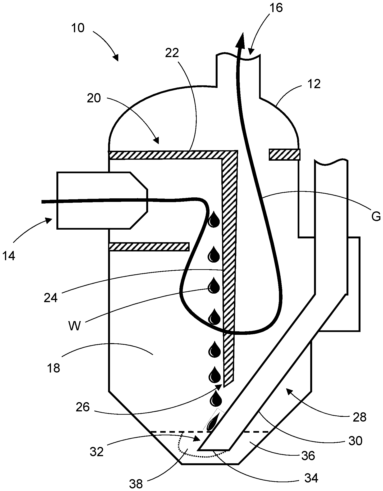
Die
Innerhalb des Abscheidergehäuses 12 befindet sich eine Abscheidekammer 18, in welche die Gasströmung G einleitbar ist. Innerhalb der Abscheidekammer 18 befindet sich eine Abscheideeinrichtung 20 zum Abscheiden von flüssigem Wasser W aus der Gasströmung G. Die Abscheideeinrichtung 20 umfasst eine Strömungsleitkontur 22, welche die in die Abscheidekammer 18 einströmende Gasströmung G frontal auf eine Anströmfläche lenkt. Die Anströmfläche ist eine Wasserführungsfläche 24, wobei die Wasserführungsfläche 24 eine Konturierung aufweist, welche einen Abtropfpunkt 26 für das Wasser W in Richtung einer Abführleitung 28 vorgibt.Within the
Die Abführleitung 28 weist eine Außenwandung 30 auf, wobei eine weitere Wasserführungsfläche 32 durch einen Abschnitt der Außenwandung 30 der Abführleitung 28 gebildet wird. Das von der Wasserführungsfläche 24 der Abscheideeinrichtung 20 abtropfende Wasser W trifft also auf die Wasserführungsfläche 32 der Abführleitung 28 und wird über die Wasserführungsfläche 32 der Abführleitung 28 in Richtung eines Wassersammelbereichs 36 geführt. In dem Wassersammelbereich 36 sammelt sich das von der Abscheideeinrichtung 20 aus der Gasströmung G abgeschiedene flüssige Wasser W an. Die Abführleitung 28 weist eine Einlassöffnung 34 auf, welche sich in dem Wassersammelbereich 36 befindet. Die Wasserführungsflächen 24, 32 sind dazu eingerichtet, das aus der Gasströmung G abgeschiedene flüssige Wasser W gezielt in eine sich an der Einlassöffnung 34 der Abführleitung 28 befindende Tauzone 38 in dem Wassersammelbereich 36 zu bringen. Hierdurch kann eine Vereisung der Abführleitung 28 mittels des gezielt in die Tauzone 38 gebrachten Wassers W aufgelöst werden.The
Nach dem Betrieb des Brennstoffzellensystems kann in dem Wassersammelbereich 36 des Wasserabscheiders 10 Wasser W zurückbleiben, welches bei geringen Umgebungstemperaturen gefriert und die zum Abführen des Wassers W genutzte Abführleitung 28 vereisen kann. Somit besteht bei der nachfolgenden Inbetriebnahme des Brennstoffzellensystems das Risiko, dass das Wasser W aufgrund der Vereisung der Abführleitung 28 nicht aus dem Wassersammelbereich 36 abgeführt werden kann. Bei einer Inbetriebnahme des Brennstoffzellensystems heizt sich das Wasser W in der Gasströmung G um ca. 0,7°C/s bis zu einer Temperatur von 60°C auf. Wenn bei einer Inbetriebnahme des Brennstoffzellensystems das abgeschiedene Wasser W aufgrund einer Vereisung der Abführleitung 28 im Wassersammelbereich 36 zunächst nicht abgeführt werden kann, sorgt das abgeschiedene warme Wasser W für einen direkten Wärmeeintrag in die Tauzone 38, sodass zügig ein zur Einlassöffnung 34 der Abführleitung 28 führender Schmelzkanal in dem gefrorenen Wasser W entsteht. Auch wenn der Rest des sich in dem Wassersammelbereich 36 befindenden Wassers W noch gefroren ist, kann neu abgeschiedenes Wasser W direkt über den Schmelzkanal und die Abführleitung 28 abgeführt werden. Das übrige Wasser W im Wassersammelbereich 36 taut dann während der Aufwärmphase ebenfalls auf und kann über die Abführleitung 28 abgeführt werden.After operation of the fuel cell system, water W may remain in the
Die
Die Abscheideeinrichtung 20 weist eine Strömungsleitkontur 22 auf, welche die in die Abscheidekammer 18 einströmende Gasströmung G frontal auf die Wasserführungsfläche 24 lenkt. Die Strömungsleitkontur 22 definiert einen Umlaufströmungsbereich 40, in welchem die über den Strömungseinlass 14 in den Wasserabscheider 10 einströmende Gasströmung G zunächst in Umfangsrichtung geführt wird. Die Strömungsleitkontur 22 umfasst ferner eine Querschnittsverjüngung 42, entlang welcher die aus dem Umlaufströmungsbereich 40 kommende Gasströmung G zusammengeführt wird. The
Die Strömungsleitkontur 22 umfasst ferner einen Ausrichtkanal 44, entlang welchem der aus der Querschnittsverjüngung 42 kommenden Gasströmung G eine beabsichtigte Strömungsrichtung aufgeprägt wird.The
Die Gasströmung G umströmt innerhalb der Abscheidekammer 18 die Wasserführungsfläche 24 und die Abführleitung 28 und wird nach erfolgter Wasserabscheidung über den Strömungsauslass 16 wieder aus der Abscheidekammer 18 herausgeleitet.The gas flow G flows around the
Die Abführleitung 28 ist als Steigrohr ausgebildet und verläuft geneigt gegenüber einer Mittelachse der Abscheidekammer 18.The
Die Abführleitung 28 ist mit einem nicht dargestellten Abführventil verbunden, über welches durch eine Betätigung das Abführen des Wassers W aus dem Wassersammelbereich 36 über die Abführleitung 28 veranlassbar ist. Bei Betätigung des Abführventils wird Wasser W aus dem Wassersammelbereich 36 aufgrund der vorherrschenden Druckverhältnisse in und durch die Abführleitung 28 gesaugt oder in und durch die Abführleitung 28 gedrückt.The
BezugszeichenReference symbol
- 1010
- WasserabscheiderWater separator
- 1212
- AbscheidergehäuseSeparator housing
- 1414
- StrömungseinlassFlow inlet
- 1616
- StrömungsauslassFlow outlet
- 1818
- AbscheidekammerSeparation chamber
- 2020
- AbscheideeinrichtungSeparation device
- 2222
- StrömungsleitkonturFlow control contour
- 2424
- WasserführungsflächeWater flow area
- 2626
- Abtropfpunktdrip point
- 2828
- Abführleitungdischarge line
- 3030
- Außenwandungexterior wall
- 3232
- WasserführungsflächeWater flow area
- 3434
- EinlassöffnungInlet opening
- 3636
- WassersammelbereichWater collection area
- 3838
- Tauzonedew zone
- 4040
- UmlaufströmungsbereichCirculating flow area
- 4242
- QuerschnittsverjüngungCross-sectional tapering
- 4444
- AusrichtkanalAlignment channel
- GG
- GasströmungGas flow
- WW
- WasserWater
ZITATE ENTHALTEN IN DER BESCHREIBUNGQUOTES CONTAINED IN THE DESCRIPTION
Diese Liste der vom Anmelder aufgeführten Dokumente wurde automatisiert erzeugt und ist ausschließlich zur besseren Information des Lesers aufgenommen. Die Liste ist nicht Bestandteil der deutschen Patent- bzw. Gebrauchsmusteranmeldung. Das DPMA übernimmt keinerlei Haftung für etwaige Fehler oder Auslassungen.This list of documents submitted by the applicant was generated automatically and is included solely for the convenience of the reader. This list is not part of the German patent or utility model application. The DPMA assumes no liability for any errors or omissions.
Zitierte PatentliteraturCited patent literature
-
DE 10 2021 105 669 A1 [0005]
DE 10 2021 105 669 A1 [0005]
Claims (12)
Priority Applications (2)
| Application Number | Priority Date | Filing Date | Title |
|---|---|---|---|
| DE102023135394.2A DE102023135394A1 (en) | 2023-12-15 | 2023-12-15 | Water separator for a fuel cell system |
| PCT/EP2024/081886 WO2025124814A1 (en) | 2023-12-15 | 2024-11-11 | Water separator for a fuel cell system |
Applications Claiming Priority (1)
| Application Number | Priority Date | Filing Date | Title |
|---|---|---|---|
| DE102023135394.2A DE102023135394A1 (en) | 2023-12-15 | 2023-12-15 | Water separator for a fuel cell system |
Publications (1)
| Publication Number | Publication Date |
|---|---|
| DE102023135394A1 true DE102023135394A1 (en) | 2025-06-18 |
Family
ID=93562508
Family Applications (1)
| Application Number | Title | Priority Date | Filing Date |
|---|---|---|---|
| DE102023135394.2A Pending DE102023135394A1 (en) | 2023-12-15 | 2023-12-15 | Water separator for a fuel cell system |
Country Status (2)
| Country | Link |
|---|---|
| DE (1) | DE102023135394A1 (en) |
| WO (1) | WO2025124814A1 (en) |
Cited By (1)
| Publication number | Priority date | Publication date | Assignee | Title |
|---|---|---|---|---|
| US20240142054A1 (en) * | 2021-03-09 | 2024-05-02 | Hengst Se | Gas management apparatus, and method for conditioning anode gas of a fuel cell |
Citations (5)
| Publication number | Priority date | Publication date | Assignee | Title |
|---|---|---|---|---|
| WO2008090430A1 (en) * | 2007-01-22 | 2008-07-31 | Nissan Motor Co., Ltd. | Drainage apparatus for fuel cell system generation water |
| US20090162730A1 (en) * | 2007-12-25 | 2009-06-25 | Toyota Boshoku Kabushiki Kaisha | Gas-liquid separator for fuel cell system |
| DE102020113104A1 (en) * | 2020-05-14 | 2021-11-18 | Audi Aktiengesellschaft | Water separator for a fuel cell device and fuel cell device with such |
| DE102021120962A1 (en) * | 2021-08-11 | 2023-02-16 | Svm Schultz Verwaltungs-Gmbh & Co. Kg | separator |
| DE112019001116B4 (en) * | 2019-10-28 | 2023-08-31 | Joma-Polytec Gmbh | liquid separator |
Family Cites Families (5)
| Publication number | Priority date | Publication date | Assignee | Title |
|---|---|---|---|---|
| GB2515463B (en) * | 2013-04-24 | 2021-04-21 | Intelligent Energy Ltd | A fuel cell system |
| JP2021182476A (en) * | 2020-05-18 | 2021-11-25 | トヨタ紡織株式会社 | Gas-liquid separator for fuel cell |
| DE102020004533A1 (en) * | 2020-07-27 | 2022-01-27 | Cellcentric Gmbh & Co. Kg | liquid separator |
| DE102021105669A1 (en) | 2021-03-09 | 2022-09-15 | Hengst Se | Gas management device and method for conditioning anode gas of a fuel cell |
| CN114865012B (en) * | 2022-05-06 | 2023-12-26 | 国家电投集团氢能科技发展有限公司 | Gas-water separator and fuel cell hydrogen supply system |
-
2023
- 2023-12-15 DE DE102023135394.2A patent/DE102023135394A1/en active Pending
-
2024
- 2024-11-11 WO PCT/EP2024/081886 patent/WO2025124814A1/en active Pending
Patent Citations (5)
| Publication number | Priority date | Publication date | Assignee | Title |
|---|---|---|---|---|
| WO2008090430A1 (en) * | 2007-01-22 | 2008-07-31 | Nissan Motor Co., Ltd. | Drainage apparatus for fuel cell system generation water |
| US20090162730A1 (en) * | 2007-12-25 | 2009-06-25 | Toyota Boshoku Kabushiki Kaisha | Gas-liquid separator for fuel cell system |
| DE112019001116B4 (en) * | 2019-10-28 | 2023-08-31 | Joma-Polytec Gmbh | liquid separator |
| DE102020113104A1 (en) * | 2020-05-14 | 2021-11-18 | Audi Aktiengesellschaft | Water separator for a fuel cell device and fuel cell device with such |
| DE102021120962A1 (en) * | 2021-08-11 | 2023-02-16 | Svm Schultz Verwaltungs-Gmbh & Co. Kg | separator |
Cited By (1)
| Publication number | Priority date | Publication date | Assignee | Title |
|---|---|---|---|---|
| US20240142054A1 (en) * | 2021-03-09 | 2024-05-02 | Hengst Se | Gas management apparatus, and method for conditioning anode gas of a fuel cell |
Also Published As
| Publication number | Publication date |
|---|---|
| WO2025124814A1 (en) | 2025-06-19 |
Similar Documents
| Publication | Publication Date | Title |
|---|---|---|
| DE3904852C2 (en) | Air inlet for the propulsion device of an aircraft | |
| EP2502300B1 (en) | Fuel cell system with gas-liquid separator in anode recirculation path | |
| DE112019001116B4 (en) | liquid separator | |
| EP3657584B1 (en) | Cooling and gas dehumidifying system, transport means and method for operating a cooling and gas dehumidifying system | |
| DE102020210612A1 (en) | Heat exchanger arrangement and fuel cell vehicle | |
| EP4313365B1 (en) | Water separator with a throttle element, use of a water separator and fuel cell system with a water separator | |
| WO2019020766A9 (en) | TEMPERATURE DEVICE FOR TEMPERATING A BATTERY SYSTEM AND BATTERY SYSTEM | |
| DE102023135394A1 (en) | Water separator for a fuel cell system | |
| DE102021202857A1 (en) | Device for separating and collecting water from a gas stream, fuel cell system and method for operating a fuel cell system | |
| DE102015200111A1 (en) | Cooling system with a water separator and method of operating a cooling system | |
| DE102012010180A1 (en) | Coolant surge tank used in cooling system of e.g. polymer electrolyte membrane (PEM) fuel cell in fuel cell system, has liquid guide device that is provided for wetting of relief valve with cooling medium | |
| DE102011113020A1 (en) | Separating device for a fuel cell system, fuel cell system with the separation device and method for operating the separation device | |
| EP2875290B1 (en) | Fresh air supply device and method for supplying fresh air to an offshore facility | |
| EP4188578B1 (en) | Liquid separator | |
| DE102016010450A1 (en) | Liquid separator and its use | |
| DE102015118419A1 (en) | END PLATE OF A FUEL CELL | |
| DE102007028298A1 (en) | Encapsulated separator assembly for integration in a gas supply of a fuel cell system | |
| DE102017208227A1 (en) | Low-pressure collector for a refrigeration system of a vehicle and refrigeration system with a low-pressure collector | |
| EP2539047B1 (en) | Pipe and condensate boundary film collection and drainage device for installation in said pipe | |
| DE102016213093A1 (en) | Method for operating a fuel cell system and fuel cell system | |
| DE102004026908A1 (en) | Apparatus for purifying an impurity-laden gas stream comprises a condenser with a dew point zone in which the impurity condenses or freezes and a system for removing the condensed or frozen impurity from the condenser | |
| DE102021005359A1 (en) | Device for cooling the mixing water for the production of fresh concrete | |
| DE102021005341A1 (en) | Device for cooling liquids | |
| EP1736229B1 (en) | Device for condensate separation | |
| WO2015176814A1 (en) | Separating device for separating a gaseous from a liquid phase of a two-phase material flow |
Legal Events
| Date | Code | Title | Description |
|---|---|---|---|
| R079 | Amendment of ipc main class |
Free format text: PREVIOUS MAIN CLASS: B01D0045000000 Ipc: B01D0045180000 |
|
| R163 | Identified publications notified |