DE102023125991A1 - Connector part with strain relief - Google Patents
Connector part with strain relief Download PDFInfo
- Publication number
- DE102023125991A1 DE102023125991A1 DE102023125991.1A DE102023125991A DE102023125991A1 DE 102023125991 A1 DE102023125991 A1 DE 102023125991A1 DE 102023125991 A DE102023125991 A DE 102023125991A DE 102023125991 A1 DE102023125991 A1 DE 102023125991A1
- Authority
- DE
- Germany
- Prior art keywords
- strain relief
- relief device
- cable
- connector part
- housing
- Prior art date
- Legal status (The legal status is an assumption and is not a legal conclusion. Google has not performed a legal analysis and makes no representation as to the accuracy of the status listed.)
- Pending
Links
Images


Classifications
-
- H—ELECTRICITY
- H01—ELECTRIC ELEMENTS
- H01R—ELECTRICALLY-CONDUCTIVE CONNECTIONS; STRUCTURAL ASSOCIATIONS OF A PLURALITY OF MUTUALLY-INSULATED ELECTRICAL CONNECTING ELEMENTS; COUPLING DEVICES; CURRENT COLLECTORS
- H01R13/00—Details of coupling devices of the kinds covered by groups H01R12/70 or H01R24/00 - H01R33/00
- H01R13/58—Means for relieving strain on wire connection, e.g. cord grip, for avoiding loosening of connections between wires and terminals within a coupling device terminating a cable
- H01R13/5837—Means for relieving strain on wire connection, e.g. cord grip, for avoiding loosening of connections between wires and terminals within a coupling device terminating a cable specially adapted for accommodating various sized cables
-
- B—PERFORMING OPERATIONS; TRANSPORTING
- B60—VEHICLES IN GENERAL
- B60L—PROPULSION OF ELECTRICALLY-PROPELLED VEHICLES; SUPPLYING ELECTRIC POWER FOR AUXILIARY EQUIPMENT OF ELECTRICALLY-PROPELLED VEHICLES; ELECTRODYNAMIC BRAKE SYSTEMS FOR VEHICLES IN GENERAL; MAGNETIC SUSPENSION OR LEVITATION FOR VEHICLES; MONITORING OPERATING VARIABLES OF ELECTRICALLY-PROPELLED VEHICLES; ELECTRIC SAFETY DEVICES FOR ELECTRICALLY-PROPELLED VEHICLES
- B60L53/00—Methods of charging batteries, specially adapted for electric vehicles; Charging stations or on-board charging equipment therefor; Exchange of energy storage elements in electric vehicles
- B60L53/10—Methods of charging batteries, specially adapted for electric vehicles; Charging stations or on-board charging equipment therefor; Exchange of energy storage elements in electric vehicles characterised by the energy transfer between the charging station and the vehicle
- B60L53/14—Conductive energy transfer
- B60L53/16—Connectors, e.g. plugs or sockets, specially adapted for charging electric vehicles
Landscapes
- Engineering & Computer Science (AREA)
- Power Engineering (AREA)
- Transportation (AREA)
- Mechanical Engineering (AREA)
- Details Of Connecting Devices For Male And Female Coupling (AREA)
Abstract
Ein Steckverbinderteil (1) zum steckenden Verbinden mit einem Gegensteckverbinderteil, aufweisend einen steckend mit dem Gegensteckverbinderteil zu verbindenden Steckabschnitt (11), zumindest ein mit einer Leitung (100) verbindbares, elektrisches Kontaktelement (111A-111N), das in dem Steckabschnitt (11) anordenbar ist, ein Gehäuseteil (3) und einen mit dem Gehäuseteil (3) verbindbaren Gehäusedeckel (4), und eine Zugentlastungseinrichtung (2, 2'-2'''), die ausgebildet ist eine mit dem zumindest einen Kontaktelement (111A-111N) verbundene Leitung (100) aufzunehmen und klemmend festzulegen, aufweisend eine erste und eine zweite Klemmeinrichtung (21A, 21B) und zwei Abstandselemente (23A, 23A'-23A''', 23B, 23B'-23B'''), die jeweils zwischen der ersten und zweiten Klemmeinrichtung (21A, 21B) anordenbar sind, wobei der Gehäusedeckel (4) eine Durchgangsöffnung zum Hindurchführen der Leitung (100) aufweist, und wobei die Zugentlastungseinrichtung (2, 2'-2''') an dem Gehäuseteil (3) anordenbar ist und in montierter Stellung des Gehäusedeckels (4) von dem Gehäusedeckel (4) an dem Gehäuseteil (3) gehalten wird.
Description
Die Erfindung betrifft ein Steckverbinderteil zum steckenden Verbinden mit einem Gegensteckverbinderteil nach dem Oberbegriff des Anspruchs 1.The invention relates to a connector part for plugging into a mating connector part according to the preamble of
Ein derartiges Steckverbinderteil umfasst einen steckend mit dem Gegensteckverbinderteil zu verbindenden Steckabschnitt, zumindest ein mit einer Leitung verbindbares, elektrisches Kontaktelement, das in dem Steckabschnitt anordenbar ist, ein Gehäuseteil und einen mit dem Gehäuseteil verbindbaren Gehäusedeckel.Such a connector part comprises a plug-in section to be connected to the mating connector part, at least one electrical contact element that can be connected to a line and can be arranged in the plug-in section, a housing part and a housing cover that can be connected to the housing part.
Ein solches Steckverbinderteil kann beispielsweise bei einem Ladesystem zum Aufladen eines Elektrofahrzeugs zum Einsatz kommen und kann beispielsweise als sogenannte Ladedose ausgebildet sein, die beispielsweise fest mit einem Fahrzeug verbunden ist und in die ein Ladestecker zum Herstellen einer elektrischen Verbindung zu einer Ladesäule eingesteckt werden kann. Alternativ kann ein solches Steckverbinderteil beispielsweise aber auch einen Ladestecker verwirklichen, der in eine zugeordnete Ladedose eingesteckt werden kann.Such a connector part can be used, for example, in a charging system for charging an electric vehicle and can be designed, for example, as a so-called charging socket, which is permanently connected to a vehicle and into which a charging plug can be plugged to establish an electrical connection to a charging station. Alternatively, such a connector part can also be implemented, for example, as a charging plug that can be plugged into an associated charging socket.
Bei einem solchen Steckverbinderteil sind ein oder mehrere elektrische Kabel oder Leitungen mit ein oder mehreren elektrischen Kontaktelementen verbunden. Die Kontaktelemente sind derart angeordnet, dass sie in den Bereich des Steckabschnitts reichen und somit bei einem steckenden Verbinden mit einem zugeordneten Gegensteckverbinderteil über die Kontaktelemente eine elektrische Verbindung zu dem Gegensteckverbinderteil, insbesondere daran angeordneten Gegenkontaktelementen, hergestellt werden kann.In such a connector part, one or more electrical cables or lines are connected to one or more electrical contact elements. The contact elements are arranged such that they extend into the area of the plug-in section, and thus, upon plugging into an associated mating connector part, an electrical connection to the mating connector part, in particular to the mating contact elements arranged thereon, can be established via the contact elements.
Bei einem solchen Steckverbinderteil ist es erforderlich, eine Zugentlastung für die mit den Kontaktelementen verbundene elektrische Leitung zur Verfügung zu stellen, um eine Übertragung von an der Leitung wirkenden Kräften auf die Kontaktelemente zu verhindern. Für eine solche Zugentlastung ist erforderlich, die mit den Kontaktelementen verbundene Leitung so zu dem Gehäuse festzulegen, dass Kräfte, die beispielsweise an der Leitung wirken, in das Gehäuse abgeleitet werden und nicht auf die Kontaktelemente wirken.Such a connector component requires strain relief for the electrical cable connected to the contact elements to prevent the transmission of forces acting on the cable to the contact elements. To achieve such strain relief, the cable connected to the contact elements must be secured to the housing in such a way that forces acting on the cable, for example, are diverted into the housing and do not affect the contact elements.
Wünschenswert ist hierbei, eine Zugentlastung für unterschiedliche Leistungsgrößen mit wenigen preisgünstigen Bauteilen in das Steckverbinderteil zu integrieren, die zudem einfach zu handhaben ist, so dass die Zugentlastung bei der Montage des Steckverbinderteils in einfacher Weise hergestellt werden kann.It is desirable to integrate a strain relief for different power sizes into the connector part using a few inexpensive components, which is also easy to handle so that the strain relief can be easily created during assembly of the connector part.
Zugentlastungen für unterschiedliche Leitungsgrößen sind beispielsweise in der
Aufgabe der vorliegenden Erfindung ist es, bei einem Steckverbinderteil eine Zugentlastung für eine an zumindest ein Kontaktelement angeschlossene Leitung bereitzustellen, die für unterschiedliche Leitungsgrößen geeignet ist und leicht zu handhaben ist.The object of the present invention is to provide a strain relief for a cable connected to at least one contact element in a connector part, which is suitable for different cable sizes and is easy to handle.
Diese Aufgabe wird durch einen Gegenstand mit den Merkmalen des Anspruchs 1 gelöst.This object is achieved by an article having the features of
Demnach weist das Steckverbinderteil eine Zugentlastungseinrichtung auf, die ausgebildet ist eine mit dem zumindest einen Kontaktelement verbundene Leitung aufzunehmen und klemmend festzulegen, aufweisend eine erste und eine zweite Klemmeinrichtung und zwei Abstandselemente, die jeweils zwischen der ersten und zweiten Klemmeinrichtung anordenbar sind, wobei der Gehäusedeckel eine Durchgangsöffnung zum Hindurchführen der Leitung aufweist, und wobei die Zugentlastungseinrichtung an dem Gehäuseteil anordenbar ist und in montierter Stellung des Gehäusedeckels von dem Gehäusedeckel an dem Gehäuseteil gehalten wird.Accordingly, the connector part has a strain relief device which is designed to receive a line connected to the at least one contact element and to secure it by clamping, comprising a first and a second clamping device and two spacer elements which can each be arranged between the first and second clamping device, wherein the housing cover has a through-opening for the passage of the line, and wherein the strain relief device can be arranged on the housing part and is held on the housing part by the housing cover in the mounted position of the housing cover.
Das Gehäuseteil kann den mit dem Gegensteckverbinderteil zu verbindenden Steckabschnitt aufweisen, oder alternativ mehrteilig aufgebaut sein, wobei ein Gehäuseelement des Gehäuseteils den Steckabschnitt aufweisen kann.The housing part can have the plug-in section to be connected to the mating connector part, or alternatively can be constructed in several parts, wherein a housing element of the housing part can have the plug-in section.
Die Leitung kann hierin auch als Lastkabel oder nur als Kabel bezeichnet werden und zumindest einen Leiter aus einem elektrisch leitfähigen Werkstoff, wie beispielsweise Kupfer, aufweisen, der mit dem Kontaktelement verbunden ist. Die Leitung kann aber auch mehr als nur einen Leiter aufweisen, wie beispielsweise 5 oder 7 Leiter, die voneinander isoliert in der Leitung verlaufen und an entsprechende Kontaktelemente angeschlossen sind, die in dem Steckabschnitt anordenbar sind. Der Leiterquerschnitt kann zumindest bereichsweise zylindrisch, quadratisch, rechteckig oder flach ausgebildet sein. Der Leiter kann eine Isolierhülle aus einem Kunststoffmaterial aufweisen, wie beispielsweise aus PE (Polyethylen), PP (Polypropylen), PVC (Polyvinylchlorid), PUR (Polyurethan), usw.The cable can also be referred to herein as a load cable or simply as a cable and can have at least one conductor made of an electrically conductive material, such as copper, which is connected to the contact element. However, the cable can also have more than one conductor, such as 5 or 7 conductors, which run insulated from one another in the cable and are connected to corresponding contact elements that can be arranged in the plug-in section. The conductor cross-section can be cylindrical, square, rectangular, or flat, at least in some areas. The conductor can have an insulating sheath made of a plastic material, such as PE (polyethylene), PP (polypropylene), PVC (polyvinyl chloride), PUR (polyurethane), etc.
Die Zugentlastungseinrichtung kann in montierter Stellung klemmend an der Leitung, beziehungsweise an einem Abschnitt der Leitung festgelegt sein, so dass ein Verschieben der Zugentlastungseinrichtung entlang einer Ausdehnungsrichtung der Leitung verhindert wird. Hierfür weist die Zugentlastungseinrichtung zwei Klemmeinrichtungen auf. Die Klemmeinrichtungen können bandartig aus einem Metall- oder Kunststoffmaterial ausgebildet sein. Weiterhin können die Klemmeinrichtungen jeweils einen gewölbten Bereich aufweisen, der im Wesentlichen einer äußeren Geometrie der Leitung entsprechen kann. In montierter Stellung können die gewölbten Bereiche um die Leitung herum angeordnet sein.In the mounted position, the strain relief device can be clamped to the cable or to a section of the cable, preventing displacement of the strain relief device along an extension direction of the cable. For this purpose, the strain relief device has two clamping devices. The clamping devices can be formed in a band-like manner from a metal or plastic material. Furthermore, the clamping devices can each have a curved region that can essentially correspond to an external geometry of the cable. In the mounted position, the curved regions can be arranged around the cable.
Die beiden Abstandselemente sind jeweils zwischen der ersten und der zweiten Klemmeinrichtung anordenbar, beziehungsweise in montierter Stellung angeordnet. Als Abstandselement kann hierein ein blockartig ausgestalteter Materialabschnitt eines Metall- oder Kunststoffmaterials verstanden werden, mit dem ein Abstand zwischen den Klemmeinrichtungen vergrößert werden kann. Ein Abstandselement kann jeweils zwischen korrespondierenden Endbereichen der Klemmeinrichtungen angeordnet werden, um den Abstand zwischen den Klemmeinrichtungen zu vergrößern.The two spacer elements can be arranged between the first and second clamping devices, or are arranged in the assembled position. A spacer element can be understood here as a block-shaped section of a metal or plastic material with which the distance between the clamping devices can be increased. A spacer element can be arranged between corresponding end regions of the clamping devices in order to increase the distance between the clamping devices.
Durch die Verwendung von Abstandselementen aus einer Vielzahl von Abstandselementen mit unterschiedlicher Höhe kann vorteilhaft die Zugentlastungseinrichtung modular für unterschiedliche Leitungsgrößen, d.h. Leitungsdurchmesser oder Leitungsquerschnitte konfiguriert werden, so dass die Zugentlastungseinrichtung sicher klemmend an der Leitung festgelegt werden kann, ohne die Leitung zu beschädigen.By using a variety of spacer elements with different heights, the strain relief device can advantageously be configured modularly for different cable sizes, i.e. cable diameters or cable cross-sections, so that the strain relief device can be securely clamped to the cable without damaging the cable.
Die Zugentlastungseinrichtung ist an dem Gehäuseteil (3) anordenbar, beziehungswiese zumindest bereichsweise in das Gehäuseteil einbringbar. Beispielsweise kann die Zugentlastungseinrichtung in eine Öffnung des Gehäuseteils einbringbar, beispielsweise eingesteckt, werden und ist in montierter Stellung in das Gehäuseteil zumindest bereichsweise eingebracht und wird von dem Gehäusedeckel in dem, beziehungsweise an dem Gehäuseteil gehalten. Der Gehäusedeckel weist eine Durchgangsöffnung auf, durch die sich die Leitung aus dem Gehäuseteil erstreckt. Der Gehäusedeckel kann schalenartig den Bereich der Zugentlastungseinrichtung, der aus dem Gehäuseteil hervorsteht umhüllen und ist in montierter Stellung mit dem Gehäuseteil verbunden, beispielsweise kann der Gehäusedeckel an das Gehäuseteil angeschraubt sein.The strain relief device can be arranged on the housing part (3) or can be introduced into the housing part at least in part. For example, the strain relief device can be introduced into an opening in the housing part, for example plugged in, and in the mounted position is introduced into the housing part at least in part and is held by the housing cover in or on the housing part. The housing cover has a through-opening through which the cable extends out of the housing part. The housing cover can enclose the area of the strain relief device that protrudes from the housing part in a shell-like manner and is connected to the housing part in the mounted position, for example, the housing cover can be screwed to the housing part.
Durch Aufnahme der Zugentlastungseinrichtung in einem Raum, der von dem Gehäuseteil und dem Gehäusedeckel begrenzt wird, kann die Zugentlastungseinrichtung und die darin eingeklemmte Leitung an dem Gehäuseteil gehalten werden, sodass Kräfte, die auf die Leitung wirken, nicht auf ein Kontaktelement an das die Leitung angeschlossen ist, übertragen werden können.By accommodating the strain relief device in a space delimited by the housing part and the housing cover, the strain relief device and the cable clamped therein can be held to the housing part so that forces acting on the cable cannot be transmitted to a contact element to which the cable is connected.
Zum Herstellen der Zugentlastung wird zunächst die Leitung in den Klemmeinrichtungen klemmend festgelegt, bzw. die Zugentlastungseinrichtung um die Leitung angeordnet. Danach wird die Zugentlastungseinrichtung an dem Gehäuseteil angeordnet, beziehungsweise zumindest teilweise in das Gehäuseteil eingebracht und der Gehäusedeckel mit dem Gehäuseteil verbunden.To create the strain relief, the cable is first clamped in the clamping devices, or the strain relief device is arranged around the cable. The strain relief device is then attached to the housing part, or at least partially inserted into the housing part, and the housing cover is connected to the housing part.
Dadurch, dass die Zugentlastungseinrichtung als separate Baugruppe ausgebildet ist, kann die Zugentlastungseinrichtung einfach an verschiedene Leitungen mit unterschiedlichen Durchmessern angeklemmt werden, bevor die Zugentlastungseinrichtung an, beziehungsweise in dem Gehäuseteil angeordnet wird.Because the strain relief device is designed as a separate assembly, the strain relief device can be easily clamped to various cables with different diameters before the strain relief device is arranged on or in the housing part.
In einer Ausgestaltung ist der Gehäusedeckel mit dem Gehäuseteil lösbar verbindbar, insbesondere über eine Schraub- oder Rastverbindung. Beispielsweise ist der Gehäusedeckel mit dem Gehäuseteil formschlüssig verbindbar, beziehungsweise in montierter Stellung formschlüssig verbunden.In one embodiment, the housing cover can be detachably connected to the housing part, in particular via a screw or snap-in connection. For example, the housing cover can be positively connected to the housing part, or is positively connected in the assembled position.
In einer Ausgestaltung weist das Gehäuseteil und die Zugentlastungseinrichtung jeweils zumindest ein erstes Kopplungselement auf, wobei die ersten Kopplungselemente zueinander korrespondierend ausgestaltet sind, zum Festlegen der Zugentlastungseinrichtung an dem Gehäuseteil.In one embodiment, the housing part and the strain relief device each have at least one first coupling element, wherein the first coupling elements are configured to correspond to one another for fixing the strain relief device to the housing part.
Die ersten Kopplungselemente können auch als Ausrichtungselemente bezeichnet werden und dienen als Montagehilfe zur Ausrichtung der Zugentlastungseinrichtung auf der Leitung. Die lose montierte Zugentlastungeinrichtung kann auf der Leitung platziert werden, so dass die Leitung noch durch die Zugentlastungseinrichtung verschiebbar ist, und gegen, beziehungsweise in das Gehäuseteil geschoben werden kann. Hierbei können die ersten Kopplungselemente derart ineinandergreifen, dass die Zugentlastungseinrichtung sich nur noch in das Gehäuseteil hinein-, bzw. hinausbewegen kann, nicht aber um die eigene Achse verdreht werden kann.The first coupling elements can also be referred to as alignment elements and serve as an assembly aid for aligning the strain relief device on the cable. The loosely mounted strain relief device can be placed on the cable so that the cable can still be moved by the strain relief device and pushed against or into the housing part. The first coupling elements can interlock in such a way that the strain relief device can only move into or out of the housing part, but cannot rotate about its own axis.
In einer Ausgestaltung ist das zumindest eine erste Kopplungselement an der Zugentlastungsteinrichtung nutförmig, insbesondere als längsförmig in Ausdehnungsrichtung der aufgenommenen Leitung verlaufender Schlitz, an einem ersten Endbereich in dem Material zumindest eines der Abstandselemente ausgebildet, und das korrespondierende erste Kopplungselement an dem Gehäuseteil stegförmig, insbesondere als längsförmig in Ausdehnungsrichtung der aufgenommenen Leitung verlaufender Steg, in dem Material des Gehäuseteils ausgebildet.In one embodiment, the at least one first coupling element on the strain relief device is groove-shaped, in particular as a slot running longitudinally in the direction of extension of the accommodated line, formed at a first end region in the material of at least one of the spacer elements, and the corresponding first coupling element on the housing part is web-shaped, in particular as a web running longitudinally in the direction of extension of the accommodated line, formed in the material of the housing part.
Hierbei kann das nutförmig ausgebildete erste Kopplungselement an der Zugentlastungseinrichtung in das korrespondierende stegförmig ausgebildete Kopplungselement an dem Gehäuseelement eingreifen, beziehungsweise eingeschoben werden.In this case, the groove-shaped first coupling element on the strain relief device can be inserted into the corresponding web-shaped formed coupling element engages or is inserted into the housing element.
In einer Ausgestaltung weisen der Gehäusedeckel und die Zugentlastungseinrichtung jeweils zumindest ein zweites Kopplungselement auf, wobei die zweiten Kopplungselemente zueinander korrespondierend ausgestaltet sind, zum Festlegen der Zugentlastungseinrichtung an dem Gehäusedeckel.In one embodiment, the housing cover and the strain relief device each have at least one second coupling element, wherein the second coupling elements are configured to correspond to one another for fixing the strain relief device to the housing cover.
Die zweiten Kopplungselemente können auch als Verdrehsicherungselemente bezeichnet werden. Durch den Einsatz der zweiten Kopplungselemente, gegebenenfalls zusammen mit den ersten Kopplungselementen kann die Zugentlastungseinrichtung sicher in dem Zwischenraum, der aus Gehäuseteil und Gehäusedeckel gebildet wird, gehalten werden.The second coupling elements can also be referred to as anti-rotation elements. By using the second coupling elements, optionally together with the first coupling elements, the strain relief device can be securely held in the space formed by the housing part and the housing cover.
In einer Ausgestaltung ist das zumindest zweite Kopplungselement an der Zugentlastungsteinrichtung nutförmig, insbesondere als längsförmig in Ausdehnungsrichtung der aufgenommenen Leitung verlaufender Schlitz, an einem zweiten Endbereich in dem Material zumindest eines der Abstandselemente ausgebildet, und das korrespondierende zweite Kopplungselement ist an dem Gehäusedeckel stegförmig, insbesondere als längsförmig in Ausdehnungsrichtung der aufgenommenen Leitung verlaufender Steg, in dem Material des Gehäusedeckels ausgebildet.In one embodiment, the at least second coupling element on the strain relief device is groove-shaped, in particular as a slot running longitudinally in the direction of extension of the accommodated cable, at a second end region in the material of at least one of the spacer elements, and the corresponding second coupling element is web-shaped on the housing cover, in particular as a web running longitudinally in the direction of extension of the accommodated cable, in the material of the housing cover.
Hierbei kann der zweite Endbereich dem ersten Endbereich gegenüberliegend angeordnet sein. Weiterhin kann an einem Abstandselement an dem ersten Endbereich ein erstes Kopplungselement angeordnet sein und an dem gegenüberliegenden zweiten Endbereich ein zweites Kopplungselement angeordnet sein. Alternativ hierzu kann an einem ersten Abstandselement der beiden Abstandselemente lediglich ein erstes Kopplungselement angeordnet sein und an einem zweiten Abstandselement der beiden Abstandselemente lediglich ein zweites Kopplungselement.In this case, the second end region can be arranged opposite the first end region. Furthermore, a first coupling element can be arranged on a spacer element at the first end region, and a second coupling element can be arranged on the opposite second end region. Alternatively, only a first coupling element can be arranged on a first spacer element of the two spacer elements, and only a second coupling element can be arranged on a second spacer element of the two spacer elements.
In einer Ausgestaltung weist das Steckverbinderteil zumindest ein Verbindungselement auf, das angepasst ist einen Endbereich der Klemmeinrichtungen über eines der Abstandselemente miteinander zu verbinden, insbesondere lösbar miteinander zu verbinden.In one embodiment, the connector part has at least one connecting element which is adapted to connect an end region of the clamping devices to one another via one of the spacer elements, in particular to connect them detachably to one another.
Beispielsweise kann das Steckverbinderteil zwei gleichartig aufgebaute Verbindungselemente aufweisen, wobei ein erstes Verbindungselement die ersten Endbereiche der Klemmeinrichtungen über ein erstes Abstandselement miteinander verbindet und ein zweites Verbindungselement die zweiten Endbereiche der Klemmeinrichtungen über ein zweites Abstandselement miteinander verbindet.For example, the connector part can have two similarly constructed connecting elements, wherein a first connecting element connects the first end regions of the clamping devices to one another via a first spacer element and a second connecting element connects the second end regions of the clamping devices to one another via a second spacer element.
Hierfür können die Verbindungselemente stiftförmig ausgestaltet sein und sich durch Öffnungen in den Klemmeinrichtungen und den Abstandselementen erstrecken, um die Klemmeinrichtungen zueinander zu bewegen und zu fixieren, damit hierdurch die Leitung zwischen den beiden Klemmeinrichtungen eingeklemmt werden kann.For this purpose, the connecting elements can be pin-shaped and extend through openings in the clamping devices and the spacer elements in order to move and fix the clamping devices towards each other so that the cable can be clamped between the two clamping devices.
In einer Ausgestaltung ist das zumindest eine Verbindungselement schraubenartig ausgebildet.In one embodiment, the at least one connecting element is designed like a screw.
Beispielsweise kann das Verbindungselement als Schraube ausgebildet sein, zum Zusammenschrauben der Klemmeinrichtungen. In alternative Ausgestaltungen kann das Verbindungselement auch als Rasthaken, oder als Bajonettverbinder ausgestaltet sein.For example, the connecting element can be designed as a screw for screwing the clamping devices together. In alternative configurations, the connecting element can also be designed as a locking hook or a bayonet connector.
In einer Ausgestaltung weisen die Abstandselemente Stabelemente auf, die in Öffnungen in den Endbereichen der Klemmeinrichtungen einbringbar sind.In one embodiment, the spacer elements comprise rod elements that can be inserted into openings in the end regions of the clamping devices.
Die Stabelemente können sich von den Grundkörpern der Abstandselemente erstrecken, um in die entsprechenden Öffnungen an den Klemmeinrichtungen einzutauchen. Hierdurch kann ein stabiler Aufbau der Zugentlastungseinrichtung geschaffen werden.The rod elements can extend from the base bodies of the spacer elements to engage the corresponding openings in the clamping devices. This allows for a stable structure of the strain relief device.
In einer Ausgestaltung weist das Steckverbinderteil eine Vielzahl von Abstandselementen mit zumindest zwei voneinander verschiedenen Höhen auf, wobei die Abstandselemente Modular aus der Vielzahl von Abstandselementen auswählbar sind für einen bestimmten Leitungsdurchmesser der Leitung.In one embodiment, the connector part has a plurality of spacer elements with at least two different heights, wherein the spacer elements can be selected modularly from the plurality of spacer elements for a specific cable diameter of the cable.
Durch die Bereitstellung einer Vielzahl von Abstandselementen mit einer unterschiedlichen Höhe kann eine Zugentlastungseinrichtung für Leitungen mit unterschiedlichen Leitungsdurchmessern bereitgestellt werden.By providing a variety of spacer elements with different heights, a strain relief device can be provided for cables with different cable diameters.
Der der Erfindung zugrunde liegende Gedanke soll nachfolgend anhand der in den Figuren dargestellten Ausführungsbeispiele näher erläutert werden. Es zeigen:
-
1A ,1B Ansichten eines Ausführungsbeispiels einer Zugentlastungseinrichtung an einer Leitung in einer perspektivischen Explosionsansicht und in einer perspektivischen Ansicht, die eine montierte Stellung der Zugentlastungseinrichtung an der Leitung zeigt; -
2 eine perspektivische Detailansicht eines Abstandselements; -
3A-3D Vorderansichten von Zugentlastungseinrichtungen mit unterschiedlich hohen Abstandselementen; -
4 Perspektivische Ansichten von zwei Klemmeinrichtungen und zwei Verbindungselementen mit unterschiedlich hohen Abstandselementen; -
5 eine perspektivische Ansicht des Steckverbinderteils ohne Gehäusedeckel; -
6 eine perspektivische Ansicht eines Gehäusedeckels; -
7 eine Seitenansicht des Steckverbinderteils; -
8 eine Schnittansicht entlang der Linie A-A gemäß7 ; und -
9 eine perspektive Ansicht des Steckverbinderteils.
-
1A ,1B Views of an embodiment of a strain relief device on a cable in a perspective exploded view and in a perspective view showing a mounted position of the strain relief device on the cable; -
2 a perspective detailed view of a spacer element; -
3A-3D Front views of strain relief devices with spacer elements of different heights; -
4 Perspective views of two clamping devices and two connecting elements with spacer elements of different heights; -
5 a perspective view of the connector part without the housing cover; -
6 a perspective view of a housing cover; -
7 a side view of the connector part; -
8 a sectional view along the line AA according to7 ; and -
9 a perspective view of the connector part.
Das in
In den
Die in dem Ausführungsbeispiel gezeigten Klemmeinrichtungen 21A, 21B sind als Stanzbiegeteile aus einem Blechstreifen ausgebildet, beziehungsweise ausgestanzt. Weiterhin weisen die beiden Klemmeinrichtungen 21A, 21B jeweils einen gewölbten Bereich auf, der im Wesentlichen einer äußeren Geometrie der Leitung 100 entspricht. In der in
Die beiden in dem Ausführungsbeispiel gezeigten Abstandselemente 23A, 23B sind in der montierten Stellung jeweils zwischen der ersten und zweiten Klemmeinrichtung 21A, 21B angeordnet. Die Abstandselemente 23A, 23B sind als blockartig ausgestaltete Materialabschnitte dargestellt und dienen dem Zweck einen Abstand zwischen den Klemmeinrichtungen 21A, 21B festzulegen. Wie in den
Die Endbereiche der gezeigten Klemmeinrichtungen 21A, 21B sind in der in
Auch weisen die Abstandselemente 23A, 23B des in der
Die
Das gezeigte Abstandselement 23A weist weiterhin an einem ersten Endbereich ein erstes Kopplungselement 235A auf, das nutförmig, als längsförmig in Ausdehnungsrichtung der aufgenommenen Leitung verlaufender Schlitz, in dem Material des Abstandselements 23A ausgebildet ist und mit einem korrespondierenden ersten Kopplungselement an dem Gehäuseteil gekoppelt, beziehungsweise in Verbindung gebracht werden kann, wie es nachfolgend in der
An einem zweiten Endbereich des Abstandselements 23A, der dem ersten Endbereich gegenüberliegt, ist ein zweites Kopplungselement 237A angeordnet, das ebenfalls nutförmig als längsförmig in Ausdehnungsrichtung der aufgenommenen Leitung verlaufender Schlitz in dem Material des Abstandselements 23A ausgebildet ist und mit einem korrespondierenden zweiten Kopplungselement an dem Gehäusedeckel gekoppelt, beziehungsweise in Verbindung gebracht werden kann, wie es nachfolgend in den
Die
Die Abstandselemente 23A, 23A', 23A'', 23A''', 23B, 23B', 23B'', 23B''' in den gezeigten Ausführungsbeispielen sind an einem in montierter Stellung in Richtung der Leitung zeigenden Abschnitt konkav, also mit einer Wölbung nach Innen ausgebildet, zum Anklemmen an die Leitung.The
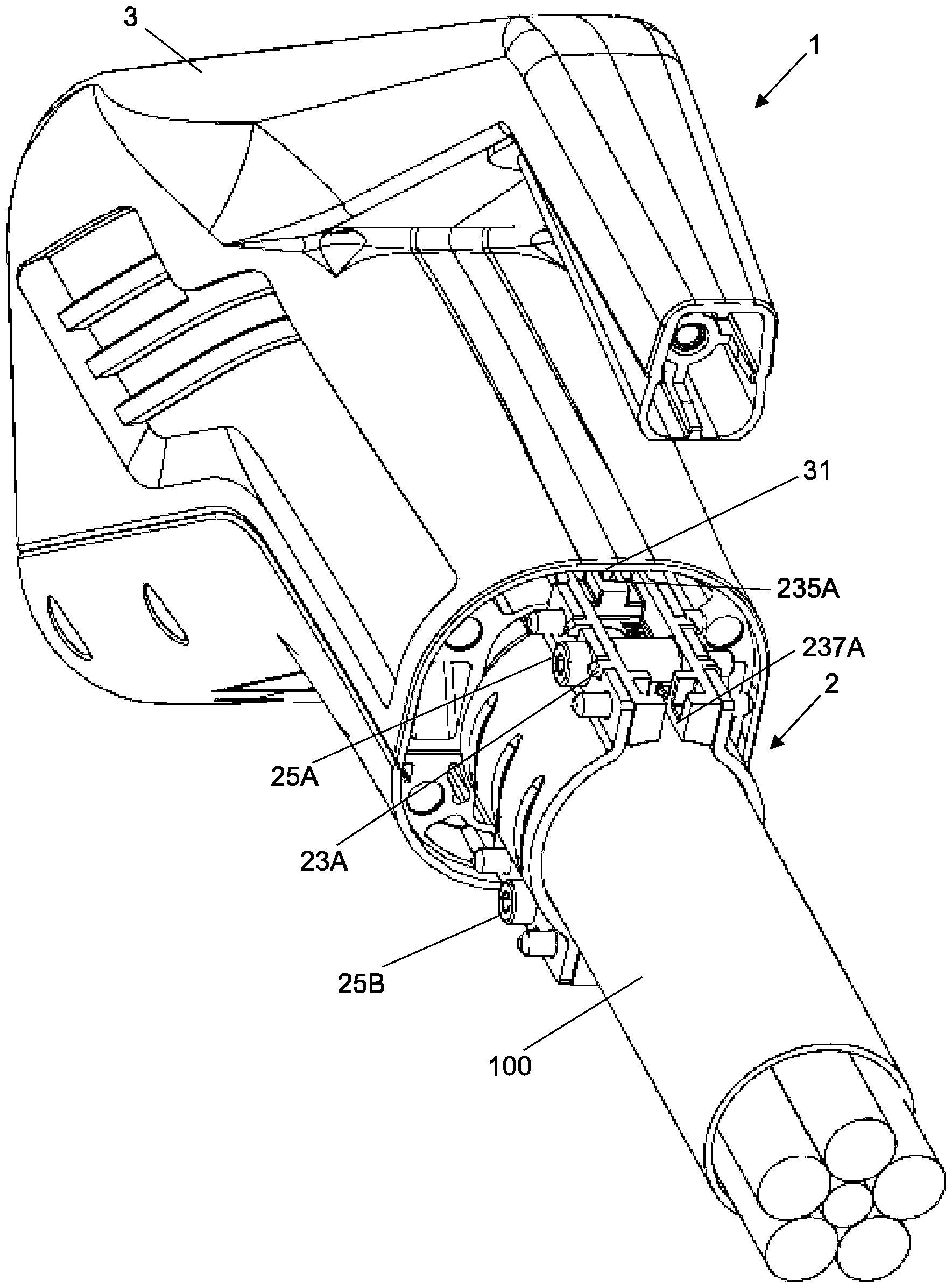
Die
Die
In dem gezeigten Ausführungsbeispiel weisen das Gehäuseteil 3 und die Zugentlastungseinrichtung 2 jeweils zumindest ein erstes Kopplungselement 31, 235A auf, die ersten Kopplungselemente 31, 235A sind zueinander korrespondierend ausgestaltet, zum Festlegen der Zugentlastungseinrichtung 2 an dem Gehäuseteil 3. Die ersten Kopplungselemente 31, 235A können als Ausrichtungselemente genutzt werden und dienen als Montagehilfe für die Ausrichtung der Zugentlastungseinrichtung 2 auf der Leitung 100. Beispielsweise kann die Zugentlastungeinrichtung 2 zunächst lose montiert auf der Leitung 100 platziert werden, indem die Verbindungselemente 25A, 25B noch nicht vollständig eingebracht sind, so dass die Leitung 100 noch durch die Zugentlastungseinrichtung 2 verschiebbar ist, und die Zugentlastungseinrichtung 2 gegen das Gehäuseteil 3 geschoben werden kann. Hierbei greifen die ersten Kopplungselemente 31, 235A derart ineinander, dass die Zugentlastungseinrichtung 2 sich nur noch in das Gehäuseteil 3 hinein-, bzw. hinausbewegen kann, nicht aber um die eigene Achse verdreht werden kann. Hierfür ist, wie bereits zuvor gezeigt, das erste Kopplungselement 235A an der Zugentlastungsteinrichtung 2 nutförmig, insbesondere als längsförmig in Ausdehnungsrichtung der aufgenommenen Leitung 100 verlaufender Schlitz, an dem ersten Endbereich in dem Material des Abstandselements 23A ausgebildet, und das korrespondierende erste Kopplungselement 31 an dem Gehäuseteil 3 ist stegförmig, als längsförmig in Ausdehnungsrichtung der aufgenommenen Leitung 100 verlaufender Steg, in dem Material des Gehäuseteils 3 ausgebildet.In the exemplary embodiment shown, the
Hierbei kann das nutförmig ausgebildete erste Kopplungselement 235A an der Zugentlastungseinrichtung 2 in das korrespondierende stegförmig ausgebildete erste Kopplungselement 31 an dem Gehäuseteil 3 eingreifen, beziehungsweise eingeschoben werden. In der
Die
In montierter Stellung kann die Leitung durch die gezeigte Durchgangsöffnung 41 geführt werden. Die gezeigten ersten Kopplungselemente 235A, 235B der Zugentlastungsreinrichtung 2 sind in montierter Stellung in die korrespondieren ersten Kopplungselemente an dem Gehäuseteil eingebracht.In the assembled position, the cable can be guided through the shown through-
In dem in
Die
In der
Die
BezugszeichenlisteList of reference symbols
- 11
- SteckverbinderteilConnector part
- 1111
- SteckabschnittPlug-in section
- 111A-111N111A-111N
- KontaktelementContact element
- 2, 2'-2'''2, 2'-2'''
- ZugentlastungseinrichtungStrain relief device
- 21A, 21B21A, 21B
- Klemmeinrichtungclamping device
- 23A, 23A'-23A''', 23B, 23B'-23B'''23A, 23A'-23A''', 23B, 23B'-23B'''
- Abstandselementspacer element
- 25A, 25B25A, 25B
- Verbindungselementconnecting element
- 211AA-211BN211AA-211BN
- Öffnungopening
- 213AA-213BN213AA-213BN
- GripelementGrip element
- 231AA-231BN231AA-231BN
- Stabelementrod element
- 233A, 233B233A, 233B
- Öffnungopening
- 235A, 235B235A, 235B
- erstes Kopplungselementfirst coupling element
- 237A, 237B237A, 237B
- zweites Kopplungselementsecond coupling element
- 33
- GehäuseteilHousing part
- 3131
- erstes Kopplungselementfirst coupling element
- 44
- GehäusedeckelHousing cover
- 4141
- Öffnungopening
- 43A, 43B43A, 43B
- zweites Kopplungselementsecond coupling element
- 4545
- Anschlagfläche Stop surface
- 100100
- LeitungLine
- 101A-101N101A-101N
- LeiterDirector
ZITATE ENTHALTEN IN DER BESCHREIBUNGQUOTES CONTAINED IN THE DESCRIPTION
Diese Liste der vom Anmelder aufgeführten Dokumente wurde automatisiert erzeugt und ist ausschließlich zur besseren Information des Lesers aufgenommen. Die Liste ist nicht Bestandteil der deutschen Patent- bzw. Gebrauchsmusteranmeldung. Das DPMA übernimmt keinerlei Haftung für etwaige Fehler oder Auslassungen.This list of documents submitted by the applicant was generated automatically and is included solely for the convenience of the reader. This list is not part of the German patent or utility model application. The DPMA assumes no liability for any errors or omissions.
Zitierte PatentliteraturCited patent literature
- DE 10 2015 112 045 B4 [0007]DE 10 2015 112 045 B4 [0007]
- DE 43 09 330 A1 [0007]DE 43 09 330 A1 [0007]
-
DE 1 758 841 U1 [0007]
DE 1 758 841 U1 [0007]
Claims (11)
Priority Applications (1)
| Application Number | Priority Date | Filing Date | Title |
|---|---|---|---|
| DE102023125991.1A DE102023125991A1 (en) | 2023-09-26 | 2023-09-26 | Connector part with strain relief |
Applications Claiming Priority (1)
| Application Number | Priority Date | Filing Date | Title |
|---|---|---|---|
| DE102023125991.1A DE102023125991A1 (en) | 2023-09-26 | 2023-09-26 | Connector part with strain relief |
Publications (1)
| Publication Number | Publication Date |
|---|---|
| DE102023125991A1 true DE102023125991A1 (en) | 2025-03-27 |
Family
ID=94875673
Family Applications (1)
| Application Number | Title | Priority Date | Filing Date |
|---|---|---|---|
| DE102023125991.1A Pending DE102023125991A1 (en) | 2023-09-26 | 2023-09-26 | Connector part with strain relief |
Country Status (1)
| Country | Link |
|---|---|
| DE (1) | DE102023125991A1 (en) |
Citations (3)
| Publication number | Priority date | Publication date | Assignee | Title |
|---|---|---|---|---|
| DE1758841U (en) | 1957-03-21 | 1957-12-27 | Karst Robert Elektrotech | CLAMP FOR FASTENING TO PIPES OF DIFFERENT DIAMETERS. |
| DE4309330A1 (en) | 1993-03-17 | 1994-09-22 | Combe Gmbh & Co Rohrbau | Spacer for pipe clamps |
| DE102015112045B4 (en) | 2015-07-23 | 2019-01-31 | Siteco Beleuchtungstechnik Gmbh | Strain relief for electrical cables |
-
2023
- 2023-09-26 DE DE102023125991.1A patent/DE102023125991A1/en active Pending
Patent Citations (3)
| Publication number | Priority date | Publication date | Assignee | Title |
|---|---|---|---|---|
| DE1758841U (en) | 1957-03-21 | 1957-12-27 | Karst Robert Elektrotech | CLAMP FOR FASTENING TO PIPES OF DIFFERENT DIAMETERS. |
| DE4309330A1 (en) | 1993-03-17 | 1994-09-22 | Combe Gmbh & Co Rohrbau | Spacer for pipe clamps |
| DE102015112045B4 (en) | 2015-07-23 | 2019-01-31 | Siteco Beleuchtungstechnik Gmbh | Strain relief for electrical cables |
Similar Documents
| Publication | Publication Date | Title |
|---|---|---|
| DE2642242C3 (en) | Detachable connection arrangement for a flexible printed circuit with a rigid printed circuit board | |
| DE4433704C2 (en) | Socket | |
| AT519366B1 (en) | CONNECTION HOUSING AND CONNECTION SYSTEM | |
| DE102013211455B4 (en) | Plug and plug system | |
| DE3004390A1 (en) | HOUSING FOR ELECTRICAL LINE CONNECTIONS | |
| WO2000030217A1 (en) | Connecting device | |
| EP2580823A1 (en) | Attachable plug-type connector | |
| WO2012022302A1 (en) | Plug-in connector | |
| BE1032009B1 (en) | Connector part with strain relief | |
| DE102019119504B4 (en) | Connector part with strain relief | |
| DE102023125991A1 (en) | Connector part with strain relief | |
| WO2019042494A1 (en) | ANGLE CONNECTOR AND METHOD OF CONFIGURATION | |
| EP3633802A1 (en) | Device socket, device plug and socket connector system | |
| DE102023100361A1 (en) | Equipotential bonding arrangement | |
| DE202022101364U1 (en) | Connector, retaining element and set consisting of a connector and a retaining element | |
| DE2716393A1 (en) | CONTACT ELEMENT FOR USE IN THE CONTACT CHAMBER OF AN INSULATING BODY | |
| DE102024115467B4 (en) | Conductor cable clamp and equipotential bonding arrangement with conductor cable clamp | |
| DE2851712C2 (en) | Connectors | |
| EP3577725B1 (en) | Plug with protective conductor bridge | |
| DE102016212324B4 (en) | Electrical connector and connector part | |
| DE102024001901B3 (en) | Fiber optic connector | |
| DE102022103338B4 (en) | Electrical connector system of a motor vehicle and motor vehicle | |
| DE202007017050U1 (en) | vehicle antenna | |
| DE10334071B4 (en) | Plug connection system with integrated lock | |
| DE202020107213U1 (en) | Connector with two protective conductor bridges |