DE102023115434A1 - Flexible connector for battery cells and method for connecting battery cells and battery cell arrangement - Google Patents
Flexible connector for battery cells and method for connecting battery cells and battery cell arrangement Download PDFInfo
- Publication number
- DE102023115434A1 DE102023115434A1 DE102023115434.6A DE102023115434A DE102023115434A1 DE 102023115434 A1 DE102023115434 A1 DE 102023115434A1 DE 102023115434 A DE102023115434 A DE 102023115434A DE 102023115434 A1 DE102023115434 A1 DE 102023115434A1
- Authority
- DE
- Germany
- Prior art keywords
- connector
- battery cell
- battery cells
- battery
- stack
- Prior art date
- Legal status (The legal status is an assumption and is not a legal conclusion. Google has not performed a legal analysis and makes no representation as to the accuracy of the status listed.)
- Pending
Links
Images


Classifications
-
- H—ELECTRICITY
- H01—ELECTRIC ELEMENTS
- H01M—PROCESSES OR MEANS, e.g. BATTERIES, FOR THE DIRECT CONVERSION OF CHEMICAL ENERGY INTO ELECTRICAL ENERGY
- H01M50/00—Constructional details or processes of manufacture of the non-active parts of electrochemical cells other than fuel cells, e.g. hybrid cells
- H01M50/50—Current conducting connections for cells or batteries
- H01M50/502—Interconnectors for connecting terminals of adjacent batteries; Interconnectors for connecting cells outside a battery casing
- H01M50/521—Interconnectors for connecting terminals of adjacent batteries; Interconnectors for connecting cells outside a battery casing characterised by the material
- H01M50/526—Interconnectors for connecting terminals of adjacent batteries; Interconnectors for connecting cells outside a battery casing characterised by the material having a layered structure
-
- H—ELECTRICITY
- H01—ELECTRIC ELEMENTS
- H01M—PROCESSES OR MEANS, e.g. BATTERIES, FOR THE DIRECT CONVERSION OF CHEMICAL ENERGY INTO ELECTRICAL ENERGY
- H01M50/00—Constructional details or processes of manufacture of the non-active parts of electrochemical cells other than fuel cells, e.g. hybrid cells
- H01M50/50—Current conducting connections for cells or batteries
- H01M50/502—Interconnectors for connecting terminals of adjacent batteries; Interconnectors for connecting cells outside a battery casing
- H01M50/503—Interconnectors for connecting terminals of adjacent batteries; Interconnectors for connecting cells outside a battery casing characterised by the shape of the interconnectors
-
- Y—GENERAL TAGGING OF NEW TECHNOLOGICAL DEVELOPMENTS; GENERAL TAGGING OF CROSS-SECTIONAL TECHNOLOGIES SPANNING OVER SEVERAL SECTIONS OF THE IPC; TECHNICAL SUBJECTS COVERED BY FORMER USPC CROSS-REFERENCE ART COLLECTIONS [XRACs] AND DIGESTS
- Y02—TECHNOLOGIES OR APPLICATIONS FOR MITIGATION OR ADAPTATION AGAINST CLIMATE CHANGE
- Y02E—REDUCTION OF GREENHOUSE GAS [GHG] EMISSIONS, RELATED TO ENERGY GENERATION, TRANSMISSION OR DISTRIBUTION
- Y02E60/00—Enabling technologies; Technologies with a potential or indirect contribution to GHG emissions mitigation
- Y02E60/10—Energy storage using batteries
Landscapes
- Chemical & Material Sciences (AREA)
- Chemical Kinetics & Catalysis (AREA)
- Electrochemistry (AREA)
- General Chemical & Material Sciences (AREA)
- Connection Of Batteries Or Terminals (AREA)
Abstract
In verschiedenen Ausführungsformen wird ein Verbinder (1) für Batteriezellen (21, 23) bereitgestellt, aufweisend: eine Anzahl von Lamellen (2) aus einem leitfähigen Material, welche übereinander zu einem Stapel angeordnet sind; wobei die Lamellen (2) in Endbereichen (B) des Stapels miteinander zusammengefügt sind und in einem zwischen den Endbereichen (B) des Stapels liegenden Bereich (A) nicht miteinander verschweißt sind. In weiteren Ausführungsformen wird ein zweiter Verbinder (1) für Batteriezellen (21, 23) bereitgestellt, aufweisend: einen Streifen aus einem leitfähigen Material, wobei entlang des Streifens mindestens eine vordefinierte Biegestelle (3) vorgesehen ist, an welcher der Streifen unter Reduktion der anzuwendenden Kraft gebogen werden kann. Ferner werden ein Verfahren zum Verbinden von Batteriezellen sowie eine entsprechend unter Verwendung des Verbinders aufgebaute Batteriezellen-Anordnung bereitgestellt.
Description
Die vorliegende Erfindung betrifft einen flexiblen Verbinder für Batteriezellen und ein Verfahren zum Verbinden von Batteriezellen sowie eine entsprechend unter Verwendung des Verbinders aufgebaute Batteriezellen-Anordnung.The present invention relates to a flexible connector for battery cells and a method for connecting battery cells as well as a battery cell arrangement constructed accordingly using the connector.
HV-Batterien, insbesondere Traktionsbatterien in einem Elektrofahrzeug, weisen üblicherweise mehrere Batteriemodule auf, in denen wiederum mehrere Batteriezellen angeordnet und elektrisch miteinander verschaltet sind. Als Batteriezellen kommen meist Lithium-Ionen-Zellen zum Einsatz.HV batteries, especially traction batteries in an electric vehicle, usually have several battery modules in which several battery cells are arranged and electrically connected to one another. Lithium-ion cells are usually used as battery cells.
Innerhalb eines Batteriemoduls liegen die Batteriezellen in einer möglichst dichten Anordnung, um eine maximale Kapazität pro Batterievolumen zu erhalten. Somit sind die Batteriezellen oftmals auch in einer Reihe angeordnet, wobei sie mit ihren hinsichtlich Polung entgegengesetzten Kontakten (Zelltabs) miteinander elektrisch verbunden sind. Aus Platzgründen sind die Batteriezellen so nah wie möglich aneinander positioniert. Dadurch gibt es an Stellen zwischen den Batteriezellen, an denen die Kontakte miteinander verbunden sind, sehr wenig Platz. Im Optimalfall sollte an den Kontakten keine Kraft eingeleitet werden, da dies zu Ablösungen der Verbindungen zwischen den Kontakten führen kann. Somit sollten die Verbindungen zwischen den Kontakten der Batteriezellen in der Lage sein, eine Krafteinleitung zu verhindern, indem sie eine Relativbewegung zwischen den Batteriezellen zulassen. Diese Relativbewegengen können während der Montage der Batteriezellen oder später während des Betriebs der HV-Batterie (z.B. durch Swelling) zustande kommen. Verbindungen zwischen den Kontakten von angrenzenden und miteinander elektrisch verbundenen Batteriezellen werden auch als Zellverbinder bezeichne.Within a battery module, the battery cells are arranged as densely as possible in order to achieve maximum capacity per battery volume. The battery cells are therefore often arranged in a row, with their contacts (cell tabs) electrically connected to one another with opposite polarity. For reasons of space, the battery cells are positioned as close to one another as possible. This means that there is very little space between the battery cells where the contacts are connected to one another. Ideally, no force should be introduced at the contacts, as this can lead to the connections between the contacts becoming detached. The connections between the contacts of the battery cells should therefore be able to prevent force introduction by allowing relative movement between the battery cells. These relative movements can occur during assembly of the battery cells or later during operation of the HV battery (e.g. due to swelling). Connections between the contacts of adjacent and electrically connected battery cells are also referred to as cell connectors.
Ein weiteres Erfordernis an eine Kontaktverbindung zwischen den Batteriezellen kann dahingehend bestehen, dass diese nicht seitlich über den Rand der Batteriezellen hinausragen darf. Dieser Raum wird oftmals bereits von anderen Komponenten eingenommen, etwa von anderen Batteriezellen, anderen Kontaktverbindungen, Kompressionspads, Kühlplatten oder der Gehäusewand des Batteriemoduls. Daher sollte eine Kontaktverbindung möglichst kompakt ausgeführt sein.Another requirement for a contact connection between the battery cells is that it must not protrude laterally beyond the edge of the battery cells. This space is often already taken up by other components, such as other battery cells, other contact connections, compression pads, cooling plates or the housing wall of the battery module. A contact connection should therefore be as compact as possible.
Aus Druckschrift
Druckschrift
Druckschrift
Vor diesem Hintergrund kann als Aufgabe der Erfindung das Bereitstellen eines Zellverbinders sowie einer entsprechenden damit aufgebauten Batteriezellen-Anordnung betrachtet werden, bei der die Batteriezellen kostengünstig und mit Toleranz- und Torsionsausgleich in mehrere Richtungen miteinander elektrisch verbunden sind.Against this background, the object of the invention can be considered to be the provision of a cell connector and a corresponding battery cell arrangement constructed therewith, in which the battery cells are electrically connected to one another in a cost-effective manner and with tolerance and torsion compensation in several directions.
Diese Aufgabe wird mittels der Gegenstände der unabhängigen Patentansprüche gelöst. Weitere bevorzugte Ausführungsformen finden sich in den abhängigen Patentansprüchen.This object is achieved by means of the subject matter of the independent patent claims. Further preferred embodiments can be found in the dependent patent claims.
Erfindungsgemäß wird in einer ersten Variante ein Verbinder für Batteriezellen bereitgestellt, aufweisend eine Anzahl von Lamellen aus einem leitfähigen Material, welche übereinander zu einem Stapel angeordnet sind. Die Lamellen sind zu den Enden des Stapels hin bzw. in den Endbereichen des Stapels miteinander zusammengefügt (z.B. verschweißt) und in einem zwischen den Enden des Stapels liegenden Bereich nicht miteinander zusammengefügt. Ein solcher Verbinder der ersten Variante kann auch als Lamellenverbinder bezeichnet werden.According to the invention, in a first variant, a connector for battery cells is provided, comprising a number of lamellae made of a conductive material, which are arranged one above the other to form a stack. The lamellae are joined together (e.g. welded) towards the ends of the stack or in the end regions of the stack and are not joined together in an area between the ends of the stack. Such a connector of the first variant can also be referred to as a lamella connector.
Bei den Lamellen kann es sich um sehr dünne und dadurch flexible, elektrisch leitende Bleche handeln. Diese können an ihren Rändern des Stapels bündig aufeinander angeordnet sein und in Außenbereichen des Stapels miteinander vollflächig oder teilweise verschweißt sein. Diese Bereiche, an denen die Lamellen zumindest teilweise miteinander verschweißt sind bilden Bereiche, die später mit Kontakten von Batteriezellen verbunden werden, z.B. durch Verschweißen. Zwischen diesen beiden Bereichen bleiben die Lamellen flexibel und sind nicht miteinander verbunden. Die verschweißten Bereiche des Verbinders werden beim späteren Aufbau einer Batteriezell-Anordnung an den Kontanten positioniert und mit diesen verschweißt und somit elektrisch und mechanisch mit den Kontakten verbunden.The lamellae can be very thin and therefore flexible, electrically conductive sheets. They can be arranged flush with one another at the edges of the stack and can be fully or partially welded together in the outer areas of the stack. These areas, where the lamellae are at least partially welded together, form areas that are later connected to contacts of battery cells, e.g. by welding. Between these two areas The lamellae remain flexible and are not connected to each other. The welded areas of the connector are positioned on the contacts during the subsequent construction of a battery cell arrangement and welded to them, thus electrically and mechanically connected to the contacts.
Gemäß einer weiteren Ausführungsform des erfindungsgemäßen Verbinders in seiner ersten Variante können die Lamellen in mindestens zwei unterschiedlichen Längen vorliegen, wobei die Lamelle mit der größten Länge und die Lamelle mit der kleinsten Länge auf unterschiedlichen Seiten des Stapels langeordnet sind.According to a further embodiment of the connector according to the invention in its first variant, the lamellae can be present in at least two different lengths, wherein the lamella with the greatest length and the lamella with the smallest length are arranged on different sides of the stack.
Gemäß einer weiteren Ausführungsform des erfindungsgemäßen Verbinders in seiner ersten Variante können die Lamellen in dem zwischen den Enden des Stapels liegenden Bereich und damit insbesondere in einem mittig liegenden Bereich des Stapels eine unterschiedliche Länge aufweisen. Dabei können die Lamelle mit der größten Länge in diesem Bereich und die Lamelle mit der kleinsten Länge in diesem Bereich auf unterschiedlichen Seiten des Stapels angeordnet sein. Zweckmäßigerweise können die Längen der Lamellen z.B. von der Unterseite des Stapels zu seiner Oberseite hin stetig zunehmen. Da die kürzeste Lamelle die effektive Länge des Verbinders festlegt, weisen durch randseitig bündiges Übereinanderlegen der Lamellen die längeren Lamellen in dem mittig liegenden Bereich des Stapels eine Wölbung auf, welche mit der Länge der Lamelle zunimmt. Wenn also die Länge der Lamellen stetig zunimmt, nimmt auch die Höhe der Wölbung von Lamelle zu Lamelle entsprechend ebenfalls zu. Dadurch kann der Verbinder für seine spätere Verwendung zum Verbinden von Batteriezellen, bei der er mindestens einmal um 180° genickt bzw. umgebogen wird, vorbereitet werden.According to a further embodiment of the connector according to the invention in its first variant, the lamellae in the area between the ends of the stack and thus in particular in a central area of the stack can have different lengths. The lamella with the greatest length in this area and the lamella with the shortest length in this area can be arranged on different sides of the stack. The lengths of the lamellae can expediently increase continuously, for example from the bottom of the stack to its top. Since the shortest lamella determines the effective length of the connector, by placing the lamellae flush on top of one another at the edges, the longer lamellae in the central area of the stack have a curvature that increases with the length of the lamella. If the length of the lamellae increases continuously, the height of the curvature from lamella to lamella also increases accordingly. This allows the connector to be prepared for its later use to connect battery cells, where it is bent or folded at least once by 180°.
Ein solcher Verbinder kann hergestellt werden, indem Lamellen mit unterschiedlichen Längen der Länge nach abnehmend übereinander angeordnet und in ein gekrümmtes Profil angeordnet werden, so dass sie an den Rändern des Stapels im Wesentlichen bündig angeordnet sind. In dieser Anordnung können die Lamellen in den randseitigen Bereichen des Stapels zusammengefügt werden. Dadurch wir dem Verbinder eine entweder eine gekrümmte Form eingeprägt oder, wenn der Verbinder wieder gerade gebogen wird, eine Wölbung im mittigen Bereich, in dem die Lamellen nicht miteinander zusammengefügt sind und auffächern können.Such a connector can be made by stacking slats of different lengths in decreasing length and arranging them in a curved profile so that they are substantially flush at the edges of the stack. In this arrangement, the slats can be joined together in the edge regions of the stack. This imparts either a curved shape to the connector or, if the connector is bent straight again, a bulge in the central region where the slats are not joined together and can fan out.
Erfindungsgemäß wird in einer zweiten Variante ein Verbinder für Batteriezellen bereitgestellt, aufweisend einen Streifen aus einem leitfähigen Material, wobei entlang des Streifens mindestens eine vordefinierte Biegestelle vorgesehen ist, an welcher der Streifen unter Reduktion der anzuwendenden Kraft gebogen werden kann.According to the invention, in a second variant, a connector for battery cells is provided, comprising a strip made of a conductive material, wherein at least one predefined bending point is provided along the strip, at which the strip can be bent while reducing the force to be applied.
Die Biegestelle kann einer Stelle entlang des Streifens entsprechen, die gegenüber den umliegenden Bereichen dünner ausgeführt ist und damit eine inhärente Soll-Schwachstelle darstellt. Alternativ kann diese Stelle mit einer Strukturierung versehen sein, die eine Materialschwächung gegenüber einem Beigemoment darstellt. Durch Ausüben eines auf die Beigestelle ausgelegten Biegemoments auf den Streifen wird der dieser nahezu ausschließlich an der Biegestelle gebogen.The bending point can correspond to a point along the strip that is thinner than the surrounding areas and thus represents an inherent weak point. Alternatively, this point can be provided with a structure that represents a weakening of the material compared to a bending moment. By applying a bending moment designed for the bending point to the strip, the strip is bent almost exclusively at the bending point.
Erfindungsgemäß wird ferner eine Batteriezellen-Anordnung bereitgestellt, aufweisend mindestens zwei Batteriezellen, die mittels des Verbinders gemäß einem der vorangehenden Ansprüche, also sowohl gemäß der ersten Variante wie auch gemäß der zweiten Variante, miteinander elektrisch verbunden sind. Die Batteriezellen können dabei in einer Reihe angeordnet sein, wobei ihre Ränder bündig ausgerichtet sind. Dabei kann es sich bei den Batteriezellen insbesondere um solche handeln, bei denen die Kontaktstellen an gegenüberliegenden Seiten angeordnet sind.According to the invention, a battery cell arrangement is also provided, having at least two battery cells that are electrically connected to one another by means of the connector according to one of the preceding claims, i.e. both according to the first variant and according to the second variant. The battery cells can be arranged in a row, with their edges aligned flush. The battery cells can in particular be those in which the contact points are arranged on opposite sides.
Gemäß weiteren Ausführungsformen der Batteriezellen-Anordnung kann der Verbinder derart zwischen den Batteriezellen angeordnet sein, dass entlang seines Verlaufs mindestens eine Richtungsumkehr erfolgt. Anders ausgedrückt kann der Verbinder in seinem zwischen zwei Batteriezellen verbauten Zustand mindestens eine 180°-Umlenkung aufweisen. Die Umlenkung kann durch ein bei der Herstellung der Batteriezellen-Anordnung erfolgendes Umklappen oder Knicken des Verbinders zustande kommen. Bei Vorhandensein von mehr als einer 180°-Umlenkung kann der Verbinder die Form einer Schlangenlinie bzw. eine mäandernde Form aufweisen.According to further embodiments of the battery cell arrangement, the connector can be arranged between the battery cells in such a way that at least one reversal of direction occurs along its course. In other words, the connector can have at least one 180° deflection when installed between two battery cells. The deflection can be brought about by folding or bending the connector during the manufacture of the battery cell arrangement. If there is more than one 180° deflection, the connector can have the shape of a serpentine line or a meandering shape.
Erfindungsgemäß wird ferner ein Verfahren zum Herstellen einer Batteriezellen-Anordnung bereitgestellt. In einem ersten Schritt weist das Verfahren Bereitstellen einer ersten Batteriezelle und einer zweiten Batteriezelle auf. Bei den Batteriezellen kann es allgemein um solche handeln, bei denen die Kontakte an gegenüberliegenden Seiten der Batteriezelle angeordnet sind. Damit einhergehend können die Batteriezellen ein quaderförmiges bzw. prismatisches Format aufweisen.According to the invention, a method for producing a battery cell arrangement is also provided. In a first step, the method comprises providing a first battery cell and a second battery cell. The battery cells can generally be those in which the contacts are arranged on opposite sides of the battery cell. In this connection, the battery cells can have a cuboid or prismatic format.
In einem weiteren Schritt weist das Verfahren Anbringen eines der Enden bzw. eines Teilbereiches eines zuvor beschriebenen Verbinders in der ersten oder zweiten Variante mit einem Kontakt der ersten Batteriezelle auf. Das Anbringen eines Endes des Verbinders an einen Kontakt kann mittels Verschweißen erfolgen.In a further step, the method comprises attaching one of the ends or a portion of a previously described connector in the first or second variant to a contact of the first battery cell. Attaching one end of the connector to a contact can be done by welding.
In einem weiteren Schritt, welcher parallel zu dem vorherigen Schritt oder in einem dazu nachgelagerten Schritt erfolgen kann, weist das Verfahren Anbringen des anderen Endes des Verbinders mit einem Kontakt der zweiten Batteriezelle auf.In a further step, which may be performed in parallel to the previous step or in a subsequent step, the method comprises attaching the other end of the connector to a contact of the second battery cell.
In einem weiteren Schritt weist das Verfahren schließlich Bewegen der ersten Batteriezelle relativ zur zweiten Batteriezelle, um den Verbinder zu derart zu verformen oder zu verbiegen, dass entlang seines Verlaufs mindestens eine Richtungsumkehr erfolgt. Anders ausgedrückt wird der Verbinder nach dem Anbringen an jeweils einen Kontakt von zwei Batteriezelle durch eine gezielt herbeigeführte Relativbewegung zwischen den beiden Batteriezellen derart verbogen, dass mindestens eine Umlenkung um 180° ausgebildet wird.In a further step, the method finally comprises moving the first battery cell relative to the second battery cell in order to deform or bend the connector in such a way that at least one reversal of direction occurs along its course. In other words, after being attached to a contact of two battery cells, the connector is bent by a targeted relative movement between the two battery cells in such a way that at least one deflection of 180° is formed.
Bei dem erfindungsgemäßen Verbinder in der ersten Variante ist der mittige Bereich, in dem die Lamellen nicht miteinander zusammengefügt sind, flexibel und lässt sich daher in diesem Bereich leicht biegen. Bei dem erfindungsgemäßen Verbinder in der zweiten Variante erfolgt die Biegung an der mindestens einen Biegestelle. Sind mehrere Biegestellen vorhanden, kann mit zwei Stützen bzw. mit einem U-Profil eine Biegestelle entlang des Verbinders ausgewählt werden, an der Verbinder gebogen bzw. umgelenkt werden soll.In the connector according to the invention in the first variant, the central area in which the slats are not joined together is flexible and can therefore be easily bent in this area. In the connector according to the invention in the second variant, the bending takes place at at least one bending point. If there are several bending points, a bending point along the connector can be selected using two supports or a U-profile, at which the connector is to be bent or deflected.
Gemäß weiteren Ausführungsformen des Verfahrens kann beim Bewegen der ersten Batteriezelle relativ zur zweiten Batteriezelle die erste Batteriezelle unter die zweite Batteriezelle versetzt oder eingeklappt werden, so dass die mittels des Verbinders miteinander verbundenen Kontakte einander gegenüberliegend angeordnet sind. Anders ausgedrückt können in der Endposition der beiden Batteriezellen Normalvektoren zu den Kotaktflächen antiparallel sein. Es wird ferner drauf hingewiesen, das beim Bewegen der ersten Batteriezelle relativ zur zweiten Batteriezelle bei Bedarf auch die zweite Batteriezelle relativ zur ersten Batteriezelle bewegt werden kann, und zwar zeitgleich oder zeitversetzt zur Bewegung der ersten Batteriezelle.According to further embodiments of the method, when the first battery cell is moved relative to the second battery cell, the first battery cell can be moved or folded under the second battery cell so that the contacts connected to one another by means of the connector are arranged opposite one another. In other words, in the end position of the two battery cells, normal vectors to the contact surfaces can be antiparallel. It is also pointed out that when the first battery cell is moved relative to the second battery cell, the second battery cell can also be moved relative to the first battery cell if necessary, at the same time or with a time delay to the movement of the first battery cell.
Gemäß weiteren Ausführungsformen des Verfahrens kann beim Bewegen der ersten Batteriezelle relativ zur zweiten Batteriezelle die erste Batteriezelle unter einer Drehung um 180° unter die zweite Batteriezelle verschwenkt oder eingeklappt wird.According to further embodiments of the method, when the first battery cell is moved relative to the second battery cell, the first battery cell can be pivoted or folded under the second battery cell by rotating it by 180°.
Im einfachsten Fall können hierbei die beiden Batteriezellen nebeneinander positioniert und der Verbinder wird mit einem Kontakt jeweils einer der beiden Batteriezellen verbunden werden. Anschließend kann eine der beiden Batteriezellen um 180° unter (oder über - je nach dem, ob der Verbinder über oder unter den nebeneinander positionierten Zellen angeordnet ist) die andere Batteriezelle gebracht oder eingeklappt werden. Im Endzustand sind die Batteriezellen bündig untereinander (oder übereinander) angeordnet, so dass die verschweißten KontaktVerbinder-Bereiche direkt aneinander anliegen. Der Verbinder wird durch das Einklappen der Batteriezelle ebenfalls um 180° gebogen.In the simplest case, the two battery cells can be positioned next to each other and the connector is connected to a contact on each of the two battery cells. One of the two battery cells can then be placed or folded in by 180° under (or over - depending on whether the connector is positioned above or below the cells positioned next to each other) the other battery cell. In the final state, the battery cells are arranged flush with each other (or on top of each other) so that the welded contact connector areas lie directly against each other. The connector is also bent by 180° when the battery cell is folded in.
Gemäß weiteren Ausführungsformen des Verfahrens kann dieses ferner Ausüben eines Druckes auf einen Teil des Verbinders oder Eindrücken ebendieses Teils aufweisen, welcher aus einem Bereich zwischen den Batteriezellen über Ränder der Batteriezellen nach außen herausragt, so dass es in diesem Teil des Verbinders zu einer Verformung kommt.According to further embodiments of the method, this may further comprise exerting pressure on a part of the connector or pressing in this part which protrudes outwards from a region between the battery cells beyond edges of the battery cells, so that deformation occurs in this part of the connector.
Diese Ausführungsform des Verfahrens kann verwendet werden, wenn der Verbinder nach seinem Anbringen an Kontakte nebeneinander positionierter Batteriezellen und dem Überführen der Batteriezellen in ihre Endposition seitlich über die beiden Batteriezellen hinausragt. Dieses kann ggfs. zu einer Kollision mit umliegenden Bauteilen führen. Um einer solche Kollision zu vermeiden, kann entweder vorab der seitlich hervorstehende Teil des Verbinders zwischen die Batteriezellen gedrückt werden, ggfs. unter Anwendung von Wärme, um den Biegevorgang zu erleichtern. Dadurch fächert sich der Verbinder der ersten Variante auf und wird plastisch verformt. Diese Form behält der Verbinder bei und kann so zusammen mit den Batteriezellen verbaut werden. Da der Verbinder nun nicht mehr über den Querschnitt der Batteriezellen-Anordnung herausragt sondern sozusagen innerhalb einer Umhüllenden des Batteriezellen-Anordnung legt, kann das Risiko einer Verhakung mit oder einer Beschädigung anderen Bauteilen vermieden werden.This embodiment of the method can be used if the connector protrudes laterally beyond the two battery cells after it has been attached to contacts of battery cells positioned next to one another and the battery cells have been moved to their final position. This can potentially lead to a collision with surrounding components. To avoid such a collision, the part of the connector that protrudes laterally can either be pressed between the battery cells in advance, if necessary using heat to facilitate the bending process. This causes the connector of the first variant to fan out and be plastically deformed. The connector retains this shape and can thus be installed together with the battery cells. Since the connector no longer protrudes beyond the cross-section of the battery cell arrangement but rather lies within an envelope of the battery cell arrangement, the risk of snagging with or damaging other components can be avoided.
Alternativ kann der Verbinder in der ersten Variante nach seinem Anbringen an die Kontakte in der herausstehenden Position belassen werden. Das Zurechtdrücken des Verbinders in den Bereich zwischen den Batteriezellen kann dann beispielsweise durch einen Stapelprozess während der Produktion des mit den Batteriezellen bestückten Batteriemoduls erfolgen. Das seitliche Eindrücken des Verbinders kann dann durch das Anlegen von benachbarten Bauteilen, etwa einer Kühlplatte, einer Trennwand oder einer anderen Batteriezelle erfolgen.Alternatively, in the first variant, the connector can be left in the protruding position after it has been attached to the contacts. The connector can then be pressed into the area between the battery cells, for example, by a stacking process during production of the battery module equipped with the battery cells. The connector can then be pressed in from the side by placing adjacent components, such as a cooling plate, a partition wall or another battery cell.
Bei dem Auffächern des Verbinders in der ersten Variante während seines Eindrückens in den Bereich zwischen den Batteriezellen kann sich zudem vorteilhafterweise seine Oberfläche vergrößern. Dadurch kann mehr Wärme in die Umgebung oder an ein Kühlmedium abgegeben werden.When the connector in the first variant is fanned out as it is pressed into the area between the battery cells, its surface area can also be advantageously enlarged. This allows more heat to be released into the environment or to a cooling medium.
Überdies können auch solche Verbinder mit vorgebogenen Geometrien bereitgestellt werden, die nach Anbringen an Kontakte an Batteriezellen nicht seitlich über den Rand der Batteriezellen herausragen.In addition, connectors with pre-bent geometries can also be provided that After being attached to contacts on battery cells, they do not protrude laterally over the edge of the battery cells.
Es können auch Batteriezellen mit einem vorgeformten Verbinder in der zweiten Variante elektrisch gekoppelt werden, der mindestens eine vordefinierte Biegestelle aufweist. Dabei können die Batteriezellen so positioniert und miteinander mittels des Verbinders elektrisch gekoppelt werden, dass die Biegestellen nach dem Zusammenfalten der beiden Batteriezellen nicht seitlich aus den Zellen herausragen. Hierzu kann der Verbinder beispielsweise eine W-Form oder eine flache Z-Form aufweisen. Der Verbinder in der zweiten Variante kann beispielsweise so vorgeformt sein, dass beim Anlegen an die Kontakte der Batteriezellen die Normalen zu den flächigen Kontanten der Batteriezellen einen von 180° bzw. 0° verschiedenen Winkel bilden.Battery cells can also be electrically coupled with a preformed connector in the second variant, which has at least one predefined bending point. The battery cells can be positioned and electrically coupled to one another using the connector in such a way that the bending points do not protrude laterally from the cells after the two battery cells have been folded together. For this purpose, the connector can have a W-shape or a flat Z-shape, for example. The connector in the second variant can, for example, be preformed in such a way that when placed on the contacts of the battery cells, the normals to the flat constants of the battery cells form an angle other than 180° or 0°.
Unabhängig von der Variante des erfindungsgemäßen Verbinders hat diese der Vorteil, dass genügend Freiraum im Bereich der Kontakte der Batteriezellen zur Verfügung steht. Dadurch gibt es für einen Schweißkopf stets einen Zugang zu den Kontakten, um den Verbinder mit diesen zu verbinden.Regardless of the variant of the connector according to the invention, it has the advantage that there is sufficient free space in the area of the contacts of the battery cells. This means that a welding head always has access to the contacts in order to connect the connector to them.
Es versteht sich, dass die voranstehend genannten und die nachstehend noch zu erläuternden Merkmale nicht nur in der jeweils angegebenen Kombination, sondern auch in anderen Kombinationen oder in Alleinstellung verwendbar sind, ohne den Rahmen der vorliegenden Erfindung zu verlassen.It is understood that the features mentioned above and those to be explained below can be used not only in the combination specified in each case, but also in other combinations or on their own, without departing from the scope of the present invention.
Weitere Vorteile und Ausgestaltungen der Erfindung ergeben sich aus der Beschreibung und den beiliegenden Zeichnungen.
-
1A zeigt ein Ausführungsbeispiel eines Verbinders in einer Variante. -
1B ein Ausführungsbeispiel eines Verbinders in der zweiten Variante. -
2 veranschaulicht einen ersten Schritt eines Ausführungsbeispiels des Verfahrens zum Herstellen einer Batteriezellen-Anordnung. -
3 veranschaulicht einen zweiten Schritt eines Ausführungsbeispiels des Verfahrens zum Herstellen einer Batteriezellen-Anordnung. -
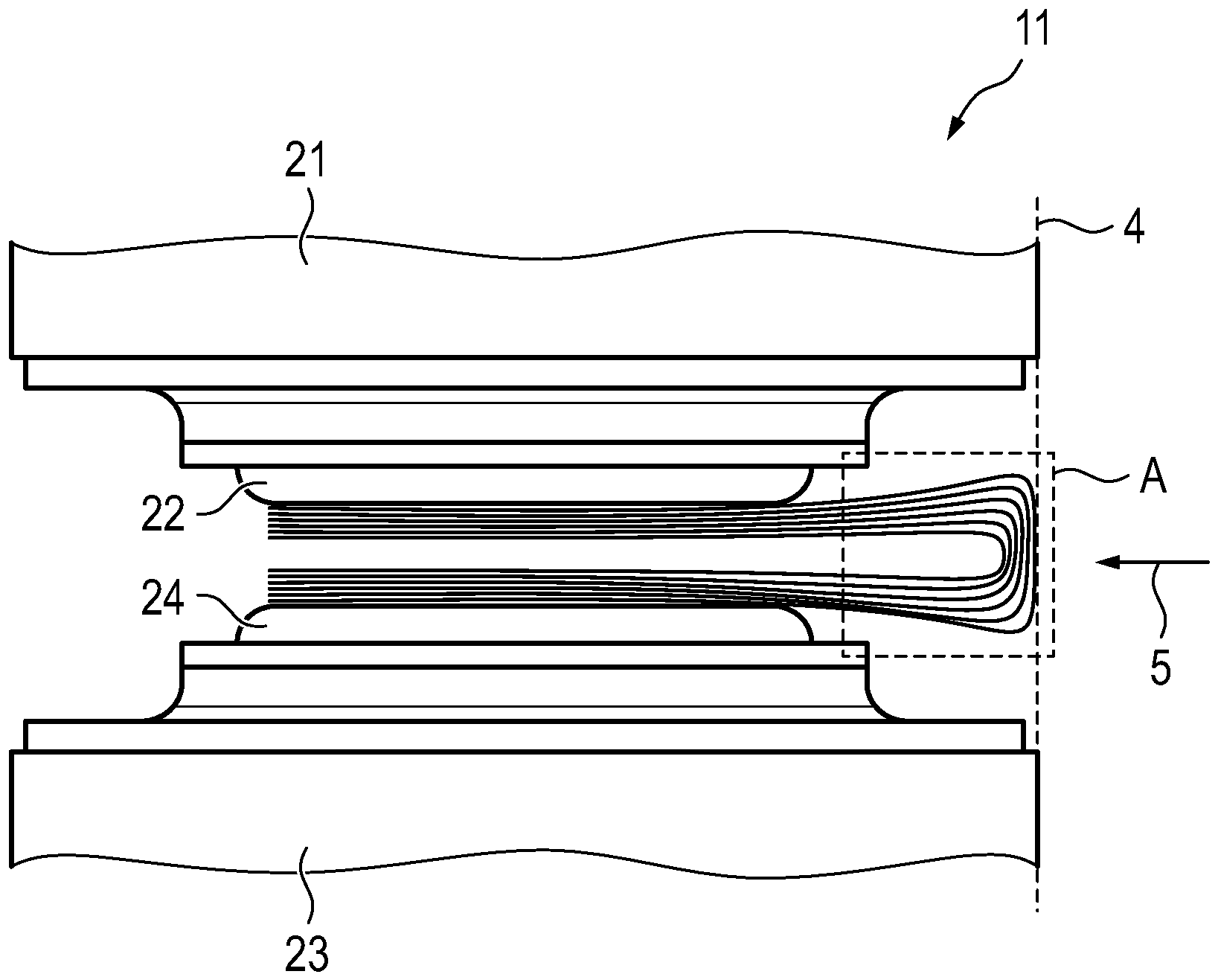
4 veranschaulicht einen dritten Schritt eines Ausführungsbeispiels des Verfahrens zum Herstellen einer Batteriezellen-Anordnung. -
5 zeigt eine Batteriezellen-Anordnung, die in einem Gehäuse verortet ist. -
6A veranschaulicht ein Ausführungsbeispiel des Verfahrens zum Herstellen einer Batteriezellen-Anordnung. -
6B veranschaulicht ein Ausführungsbeispiel des Verfahrens zum Herstellen einer Batteriezellen-Anordnung. -
6C veranschaulicht ein Ausführungsbeispiel des Verfahrens zum Herstellen einer Batteriezellen-Anordnung. -
7 zeigt ein beispielhaftes Batteriemodul, in welchem mehrere Batteriezellen-Anordnungen verbaut sind.
-
1A shows an embodiment of a connector in a variant. -
1B an embodiment of a connector in the second variant. -
2 illustrates a first step of an embodiment of the method for producing a battery cell arrangement. -
3 illustrates a second step of an embodiment of the method for producing a battery cell arrangement. -
4 illustrates a third step of an embodiment of the method for producing a battery cell arrangement. -
5 shows a battery cell arrangement located in a housing. -
6A illustrates an embodiment of the method for producing a battery cell arrangement. -
6B illustrates an embodiment of the method for producing a battery cell arrangement. -
6C illustrates an embodiment of the method for producing a battery cell arrangement. -
7 shows an example battery module in which several battery cell arrangements are installed.
In
Bei dem in
In dem gezeigten Ausführungsbeispiel des Verbinders 1 sind die Lamellen 2 an den Rändern des Stapels bündig zusammengelegt. Dadurch wird die unterschiedliche Länge der Lamellen 2 in dem zwischen den Endbereichen B des Stapels liegenden mittigen Bereich A untergebracht, in dem die Lamellen 2 von unten nach oben eine zunehmende Länge aufweisen. In dem mittigen Bereich A können sich daher die oben liegenden Lamellen 2 nach oben wölben, während eine Wölbung nach unten durch die unten angeordneten kürzeren Lamellen 2 unterbunden wird. Die Wölbung kann andererseits eine in dem gezeigten Beispiel konvexe Krümmung des Verbinders 1, je nach Steifigkeit des verwendeten Materials erleichtern oder gar herbeiführen.In the embodiment of the
In
Im Folgenden werden mit Bezug auf die
In
In
In einem dritten Schritt, welcher in
Der in
In
Im Folgenden werden mit Bezug auf die
Bei dem in
Bei dem in
Bei dem in
ZITATE ENTHALTEN IN DER BESCHREIBUNGQUOTES INCLUDED IN THE DESCRIPTION
Diese Liste der vom Anmelder aufgeführten Dokumente wurde automatisiert erzeugt und ist ausschließlich zur besseren Information des Lesers aufgenommen. Die Liste ist nicht Bestandteil der deutschen Patent- bzw. Gebrauchsmusteranmeldung. Das DPMA übernimmt keinerlei Haftung für etwaige Fehler oder Auslassungen.This list of documents listed by the applicant was generated automatically and is included solely for the better information of the reader. The list is not part of the German patent or utility model application. The DPMA accepts no liability for any errors or omissions.
Zitierte PatentliteraturCited patent literature
- DE 10 2020211091 A1 [0005]DE 10 2020211091 A1 [0005]
- DE 10 2019112372 A1 [0006]DE 10 2019112372 A1 [0006]
- DE 10 2021201496 A1 [0007]DE 10 2021201496 A1 [0007]
Claims (10)
Priority Applications (1)
| Application Number | Priority Date | Filing Date | Title |
|---|---|---|---|
| DE102023115434.6A DE102023115434A1 (en) | 2023-06-14 | 2023-06-14 | Flexible connector for battery cells and method for connecting battery cells and battery cell arrangement |
Applications Claiming Priority (1)
| Application Number | Priority Date | Filing Date | Title |
|---|---|---|---|
| DE102023115434.6A DE102023115434A1 (en) | 2023-06-14 | 2023-06-14 | Flexible connector for battery cells and method for connecting battery cells and battery cell arrangement |
Publications (1)
| Publication Number | Publication Date |
|---|---|
| DE102023115434A1 true DE102023115434A1 (en) | 2024-12-19 |
Family
ID=93654693
Family Applications (1)
| Application Number | Title | Priority Date | Filing Date |
|---|---|---|---|
| DE102023115434.6A Pending DE102023115434A1 (en) | 2023-06-14 | 2023-06-14 | Flexible connector for battery cells and method for connecting battery cells and battery cell arrangement |
Country Status (1)
| Country | Link |
|---|---|
| DE (1) | DE102023115434A1 (en) |
Citations (6)
| Publication number | Priority date | Publication date | Assignee | Title |
|---|---|---|---|---|
| DE102011077691A1 (en) | 2011-06-17 | 2012-12-20 | Robert Bosch Gmbh | Connector for electrical connections and method for connecting electrical components |
| DE102011080977A1 (en) | 2011-08-16 | 2013-02-21 | Sb Limotive Company Ltd. | Cell connector, battery cell module, battery, method for producing a cell connector and motor vehicle |
| EP2441103B2 (en) | 2009-06-08 | 2018-09-12 | Auto-Kabel Management GmbH | Battery cell connector |
| DE102019112372A1 (en) | 2019-05-13 | 2020-11-19 | Bayerische Motoren Werke Aktiengesellschaft | High-voltage battery for a motor vehicle with module connectors and motor vehicle |
| DE102020211091A1 (en) | 2020-09-02 | 2022-03-03 | Leoni Bordnetz-Systeme Gmbh | Electrical contact connector and battery |
| DE102021201496A1 (en) | 2021-02-17 | 2022-08-18 | Volkswagen Aktiengesellschaft | battery |
-
2023
- 2023-06-14 DE DE102023115434.6A patent/DE102023115434A1/en active Pending
Patent Citations (6)
| Publication number | Priority date | Publication date | Assignee | Title |
|---|---|---|---|---|
| EP2441103B2 (en) | 2009-06-08 | 2018-09-12 | Auto-Kabel Management GmbH | Battery cell connector |
| DE102011077691A1 (en) | 2011-06-17 | 2012-12-20 | Robert Bosch Gmbh | Connector for electrical connections and method for connecting electrical components |
| DE102011080977A1 (en) | 2011-08-16 | 2013-02-21 | Sb Limotive Company Ltd. | Cell connector, battery cell module, battery, method for producing a cell connector and motor vehicle |
| DE102019112372A1 (en) | 2019-05-13 | 2020-11-19 | Bayerische Motoren Werke Aktiengesellschaft | High-voltage battery for a motor vehicle with module connectors and motor vehicle |
| DE102020211091A1 (en) | 2020-09-02 | 2022-03-03 | Leoni Bordnetz-Systeme Gmbh | Electrical contact connector and battery |
| DE102021201496A1 (en) | 2021-02-17 | 2022-08-18 | Volkswagen Aktiengesellschaft | battery |
Similar Documents
| Publication | Publication Date | Title |
|---|---|---|
| DE102015217630A1 (en) | Compression element of at least one battery cell having battery module, battery module with such a compression element and method for its preparation and battery | |
| DE102018132147A1 (en) | METHOD FOR FORMING A BUSBAR AND FOLDED BUSBAR | |
| DE102016000843A1 (en) | Contacting system for energy storage cells and energy storage | |
| DE112018002974T5 (en) | ENERGY STORAGE DEVICE | |
| DE102020131528A1 (en) | Battery, automobile and battery assembly method | |
| DE102021110895A1 (en) | Battery module for a motor vehicle and method for its manufacture | |
| DE102020119107A1 (en) | Battery for a motor vehicle | |
| WO2013075843A1 (en) | Cell contacting arrangement for an energy store | |
| DE69202725T2 (en) | Connection arrangement for electrical lines. | |
| DE102023115434A1 (en) | Flexible connector for battery cells and method for connecting battery cells and battery cell arrangement | |
| DE102012218433A1 (en) | Contact element for contact arrangement, has shoulder portion arranged between contact portion and insertion portion, which is protruded laterally to contact portion and is adapted to introduce pressing force into insertion portion | |
| DE102018205952B4 (en) | Cell winding for a lithium-ion battery cell, lithium-ion battery cell, energy storage | |
| DE102019131200A1 (en) | Power-free battery module for a traction battery, method for producing a battery module, traction battery and electrically drivable motor vehicle | |
| DE102023112056A1 (en) | Fuel cell unit and assembly method therefor | |
| DE102019202132A1 (en) | accumulator | |
| DE102018216835A1 (en) | Battery module and motor vehicle | |
| DE102022108779A1 (en) | Connecting rail for an energy storage device, energy storage unit and energy storage device | |
| DE102013201689B4 (en) | shield housing | |
| DE102021125014A1 (en) | Battery cell housing for a battery cell of an electrical energy store, battery cell, electrical energy store and method | |
| DE102017211208A1 (en) | Coil device for a motor vehicle, in particular for a motor vehicle | |
| DE102021210069A1 (en) | Battery module and method of making the same | |
| DE102017111293A1 (en) | pin | |
| DE102019120496A1 (en) | CONNECTING ELEMENT FOR ELECTRICAL CONTACT AND PROCEDURE FOR PRODUCING A CONNECTING ELEMENT | |
| DE102014223178B4 (en) | Contact pressure concept for a cooling device for a high-voltage storage system | |
| DE102024003167B3 (en) | Battery module |
Legal Events
| Date | Code | Title | Description |
|---|---|---|---|
| R012 | Request for examination validly filed | ||
| R016 | Response to examination communication | ||
| R016 | Response to examination communication |