DE102022209325B4 - filter element and filter device - Google Patents
filter element and filter device Download PDFInfo
- Publication number
- DE102022209325B4 DE102022209325B4 DE102022209325.9A DE102022209325A DE102022209325B4 DE 102022209325 B4 DE102022209325 B4 DE 102022209325B4 DE 102022209325 A DE102022209325 A DE 102022209325A DE 102022209325 B4 DE102022209325 B4 DE 102022209325B4
- Authority
- DE
- Germany
- Prior art keywords
- filter element
- filter
- end plate
- end disk
- filter device
- Prior art date
- Legal status (The legal status is an assumption and is not a legal conclusion. Google has not performed a legal analysis and makes no representation as to the accuracy of the status listed.)
- Active
Links
Images


Classifications
-
- B—PERFORMING OPERATIONS; TRANSPORTING
- B01—PHYSICAL OR CHEMICAL PROCESSES OR APPARATUS IN GENERAL
- B01D—SEPARATION
- B01D29/00—Filters with filtering elements stationary during filtration, e.g. pressure or suction filters, not covered by groups B01D24/00 - B01D27/00; Filtering elements therefor
- B01D29/11—Filters with filtering elements stationary during filtration, e.g. pressure or suction filters, not covered by groups B01D24/00 - B01D27/00; Filtering elements therefor with bag, cage, hose, tube, sleeve or like filtering elements
-
- B—PERFORMING OPERATIONS; TRANSPORTING
- B01—PHYSICAL OR CHEMICAL PROCESSES OR APPARATUS IN GENERAL
- B01D—SEPARATION
- B01D46/00—Filters or filtering processes specially modified for separating dispersed particles from gases or vapours
- B01D46/24—Particle separators, e.g. dust precipitators, using rigid hollow filter bodies
- B01D46/2403—Particle separators, e.g. dust precipitators, using rigid hollow filter bodies characterised by the physical shape or structure of the filtering element
- B01D46/2411—Filter cartridges
- B01D46/2414—End caps including additional functions or special forms
-
- B—PERFORMING OPERATIONS; TRANSPORTING
- B01—PHYSICAL OR CHEMICAL PROCESSES OR APPARATUS IN GENERAL
- B01D—SEPARATION
- B01D2201/00—Details relating to filtering apparatus
- B01D2201/29—Filter cartridge constructions
- B01D2201/291—End caps
-
- B—PERFORMING OPERATIONS; TRANSPORTING
- B01—PHYSICAL OR CHEMICAL PROCESSES OR APPARATUS IN GENERAL
- B01D—SEPARATION
- B01D2201/00—Details relating to filtering apparatus
- B01D2201/40—Special measures for connecting different parts of the filter
- B01D2201/4076—Anti-rotational means
Landscapes
- Chemical & Material Sciences (AREA)
- Chemical Kinetics & Catalysis (AREA)
- Physics & Mathematics (AREA)
- Geometry (AREA)
- Filtration Of Liquid (AREA)
- Filtering Of Dispersed Particles In Gases (AREA)
Abstract
Filterelement (1) für eine Filtereinrichtung (30) zum Filtern eines Fluids,
- mit einem ringförmigen Filterkörper (2) aus Filtermaterial, der eine Filterelement-Mittellängsachse (FMA) aufweist und der zum Filtern eines Fluids von dieser radial durchströmbar ist,
- mit einer, vorzugsweise ringförmigen, oberen Endscheibe (3), die ein vom Filterkörper (2) abgewandtes oberes axiales Ende (4) des Filterelements (1) abdichtet und die eine zentrale Scheibenöffnung (5) aufweist, welche von einem Aufnahmestutzen (31) der Filtereinrichtung (30) durchsetzbar ist,
- wobei an der oberen Endscheibe (3) eine Endscheiben-Rippenstruktur (6) vorgesehen ist, mittels welcher das Filterelement (1) im montierten Zustand an einer am Aufnahmestutzen (31) vorgesehenen Endscheiben-Halterung (32) anbringbar ist,
- wobei die Endscheiben-Rippenstruktur (6) auf einer vom Filterkörper (2) abgewandten Oberseite (7) der oberen Endscheibe (3) angeordnet ist und mehrere in Umfangsrichtung (U) im Abstand zueinander angeordnete und jeweils axial nach oben von der Endscheibe (3) abstehende Rippen (8) umfasst,
dadurch gekennzeichnet, dass
- zwischen jeweils zwei in Umfangsrichtung (U) des Filterelements (1) benachbarten Rippen (8) der Endscheiben-Rippenstruktur (6) eine Vertiefung (11) vorgesehen ist,
- in dem Längsschnitt eine von der Endscheibe (3) abgewandte Oberseite (12) der Vertiefung (11) eine kurvenförmige Kontur (15) aufweist, deren axialer Abstand (b) zu einer Unterseite (13) der Endscheibe (3) in einem Kontaktpunkt (49), minimal ist.
- with an annular filter body (2) made of filter material, which has a filter element central longitudinal axis (FMA) and through which a fluid can flow radially for filtering,
- with a preferably annular upper end disc (3) which seals an upper axial end (4) of the filter element (1) facing away from the filter body (2) and which has a central disc opening (5) through which a receiving socket (31) of the filter device (30) can pass,
- wherein an end plate rib structure (6) is provided on the upper end plate (3), by means of which the filter element (1) in the assembled state can be attached to an end plate holder (32) provided on the receiving socket (31),
- wherein the end disk rib structure (6) is arranged on an upper side (7) of the upper end disk (3) facing away from the filter body (2) and comprises a plurality of ribs (8) arranged at a distance from one another in the circumferential direction (U) and each projecting axially upwards from the end disk (3),
characterized in that
- a recess (11) is provided between each two ribs (8) of the end disc rib structure (6) adjacent in the circumferential direction (U) of the filter element (1),
- in the longitudinal section, an upper side (12) of the recess (11) facing away from the end plate (3) has a curved contour (15) whose axial distance (b) to an underside (13) of the end plate (3) is minimal at a contact point (49).
Description
Die Erfindung betrifft ein Filterelement für eine Filtereinrichtung sowie eine Filtereinrichtung zum Filtern eines Fluids, insbesondere einer Flüssigkeit, mit einem solchen Filterelement.The invention relates to a filter element for a filter device and to a filter device for filtering a fluid, in particular a liquid, with such a filter element.
Eine gattungsgemäße Filtereinrichtung ist beispielsweise aus der
Eine derartige Filtereinrichtung umfasst eine Konsole - dem Fachmann auch unter der Bezeichnung „Filterkopf“ bekannt - ein Gehäuse und ein Filterelement und besitzt im montierten Zustand eine hängende oder stehende Anordnung. Die Konsole kann insbesondere bei einer hängenden Anordnung auch als Filterkopf bezeichnet werden und weist einen rohseitigen Zulauf und einen reinseitigen Ablauf auf, wobei eine Zulauföffnung des Zulaufs und eine Ablauföffnung des Ablaufs im montierten Zustand der Filtereinrichtung aufgrund der hängenden Anordnung nach unten offen sind. Das Gehäuse ist lösbar an der Konsole befestigt und enthält einen Aufnahmeraum. Das Gehäuse schließt im montierten Zustand der Filtereinrichtung aufgrund der hängenden Anordnung nach unten an die Konsole an, sodass sich der Aufnahmeraum unterhalb der Konsole befindet. Das Filterelement ist austauschbar im Aufnahmeraum angeordnet und trennt darin eine mit dem Zulauf fluidisch verbundene Rohseite von einer mit dem Ablauf fluidisch verbundenen Reinseite. Im montierten Zustand der Filtereinrichtung ist das Filterelement von unten an der Konsole lösbar festgelegt. Das Filterelement weist außerdem einen ringförmigen Filterkörper auf, der eine Mittellängsachse definiert und der zum Filtern des Fluids von dem Fluid radial durchströmbar ist. Der Ablauf weist an der Konsole einen Aufnahmestutzen auf, der die Ablauföffnung besitzt und der vorzugsweise konzentrisch zur Mittellängsachse angeordnet ist. Das Filterelement weist eine offene obere Endscheibe auf, die ein der Konsole zugewandtes oberes axiales Ende des Filterkörpers abdichtet und die eine zentrale Scheibenöffnung aufweist, die vom Aufnahmestutzen durchsetzt ist. Des Weiteren ist eine Stutzendichtung vorgesehen, die den Aufnahmestutzen gegenüber der oberen Endscheibe dichtet.Such a filter device comprises a console - also known to those skilled in the art as a "filter head" - a housing and a filter element and has a hanging or standing arrangement when assembled. The console can also be referred to as a filter head, particularly in a hanging arrangement, and has an inlet on the raw side and an outlet on the clean side, with an inlet opening of the inlet and an outlet opening of the outlet being open downwards when the filter device is assembled due to the hanging arrangement. The housing is detachably attached to the console and contains a receiving space. When the filter device is assembled, the housing connects downwards to the console due to the hanging arrangement, so that the receiving space is located below the console. The filter element is arranged in an exchangeable manner in the receiving space and separates a raw side that is fluidically connected to the inlet from a clean side that is fluidically connected to the outlet. When the filter device is assembled, the filter element is detachably attached to the console from below. The filter element also has an annular filter body which defines a central longitudinal axis and through which the fluid can flow radially to filter the fluid. The drain has a receiving nozzle on the console which has the drain opening and which is preferably arranged concentrically to the central longitudinal axis. The filter element has an open upper end disk which seals an upper axial end of the filter body facing the console and which has a central disk opening through which the receiving nozzle passes. A nozzle seal is also provided which seals the receiving nozzle against the upper end disk.
Bei einer hängenden Anordnung ist die Konsole oben angeordnet und das Fluid wird von oben dem Aufnahmeraum zugeführt und nach oben vom Aufnahmeraum abgeführt. Das Filterelement schließt nach unten an die Konsole an, sodass es quasi an der Konsole hängt. Das in der Regel topfförmige Gehäuse schließt ebenfalls von unten an die Konsole an und nimmt dabei das Filterelement auf. Im Unterschied dazu ist bei einer stehenden Anordnung die Konsole unten angeordnet und das Fluidwird von unten zugeführt und nach unten abgeführt. Das Filterelement schließt nach oben an die Konsole an, so dass es quasi auf der Konsole steht. Der Aufnahmeraum kann bei einer stehenden Anordnung in der Konsole und/oder im Gehäuse ausgebildet sein. Das Gehäuse bildet in der Regel einen Deckel und schließt nach oben an die Konsole an. Die relativen Ortsangaben „oben“ und „unten“ beziehen sich dabei auf die Schwerkraftrichtung, die nach unten weist. Im montierten Zustand der Filtereinrichtung kann der Zulauf über eine Pumpe mit einem Reservoir verbunden sein, wohingegen der Ablauf zu Verbrauchern des Fluids führt, von denen ggf. ein Rücklauf wieder zum Reservoir führt.In a hanging arrangement, the console is arranged at the top and the fluid is fed into the receiving space from above and discharged upwards from the receiving space. The filter element is connected to the console at the bottom, so that it is virtually hanging on the console. The housing, which is usually pot-shaped, is also connected to the console from below and accommodates the filter element. In contrast, in a standing arrangement, the console is arranged at the bottom and the fluid is fed into it from below and discharged downwards. The filter element is connected to the console at the top, so that it is virtually standing on the console. In a standing arrangement, the receiving space can be formed in the console and/or in the housing. The housing usually forms a cover and is connected to the console at the top. The relative location specifications "top" and "bottom" refer to the direction of gravity, which points downwards. When the filter device is installed, the inlet can be connected to a reservoir via a pump, whereas the outlet leads to consumers of the fluid, from which a return flow may lead back to the reservoir.
Beim Montieren des Filterelements wird das Filterelement mit der oberen Endscheibe auf den Aufnahmestutzen aufgesteckt. Dabei wird die Stutzendichtung radial verpresst, um die Dichtungswirkung zu erzeugen. Dadurch erzeugt die Stutzendichtung zwischen dem Aufnahmestutzen und der oberen Endscheibe eine axiale Stutzenhaltekraft, die einem Abziehen des Filterelements vom Aufnahmestutzen entgegenwirkt.When installing the filter element, the filter element is placed onto the receiving socket with the upper end plate. The socket seal is pressed radially to create the sealing effect. The socket seal between the receiving socket and the upper end plate thus creates an axial socket holding force that prevents the filter element from being pulled off the receiving socket.
Vor diesem Hintergrund offenbart die
Die
Weitere derartige Filtereinrichtungen sind aus der
Als problematisch bei solchen herkömmlichen Filtereinrichtungen erweist sich, dass sich das Filterelement im Betrieb an der Konsole „festsetzt“, was das Lösen des Filterelementes beim Filterwechsel nur unter hohem Kraftaufwand ermöglicht; denn bedingt durch die Pressung der Stutzendichtung zur vollständigen Abdichtung der Endscheibe gegen die Konsole kann es zu Verklebungen des Filterelementes mit dem Filterkopf oder zu vergleichbaren Effekten kommen. Es kommt somit an der zylindrischen Kontaktfläche der Endscheibe sowie der Konsole mit dem O-Ring durch das Medium zu einem Verkleben. Neben dem Verkleben kann es zudem zu einem Aufquellen der O-Ring-Dichtung kommen. Ein derartiges Quellen der Dichtung erhöht die resultierenden Klemmkräfte, welche bei der Demontage des Filterelementes zusätzlich überwunden werden müssen. Die Summe der Verklebungs- und Klemmkräfte müssen daher für die Demontage des gebrauchten Filterelementes beim Filterelementwechsel überwunden werden, was die Demontage deutlich erschwert.A problem with such conventional filter devices is that the filter element "sticks" to the bracket during operation, which means that the filter element can only be removed with great force when changing the filter; this is because the pressure of the nozzle seal to completely seal the end plate against the The filter element can stick to the filter head or have similar effects. This causes the medium to stick to the cylindrical contact surface of the end plate and the console with the O-ring. In addition to sticking, the O-ring seal can also swell. This type of swelling of the seal increases the resulting clamping forces, which must also be overcome when dismantling the filter element. The sum of the bonding and clamping forces must therefore be overcome to dismantle the used filter element when changing the filter element, which makes dismantling significantly more difficult.
Aufgrund der zylindrischen Kontaktfläche zwischen Aufnahmestutzen der Konsole und offener Endscheibe des Filterelementes mit geringem Spaltmaß, ist ein „Heraushebeln“ des verklebten Filterelementes aufgrund der nur in einem geringen Winkelspiel ausführbaren Hebelbewegung nur bedingt möglich. Nahezu die gesamten Klemm- und Verklebungskräfte müssen somit durch ein aufgebrachtes Torsionsmoment, eine axiale Kraft oder eine Kombination aus beidem überwunden werden. Gerade in räumlich beengten Einbausituationen kann dies erhebliche Schwierigkeiten mit sich führen und gar in Verletzungsgefahren resultieren.Due to the cylindrical contact surface between the bracket's mounting socket and the open end plate of the filter element with a small gap, it is only possible to "lever out" the bonded filter element to a limited extent due to the lever movement that can only be carried out with a small angular play. Almost all of the clamping and bonding forces must therefore be overcome by an applied torsional moment, an axial force or a combination of both. This can cause considerable difficulties, particularly in spatially confined installation situations, and can even result in the risk of injury.
Dieser Nachteil kann nicht durch eine Anpassung der Auslegung der Stutzendichtung ausgeräumt werden, da dies die erzielte Dichtungswirkung mindern oder, im Extremfall, gar außer Funktion setzen würde.This disadvantage cannot be eliminated by adapting the design of the nozzle seal, as this would reduce the achieved sealing effect or, in extreme cases, even render it inoperable.
Die vorliegende Erfindung beschäftigt sich daher mit dem Problem, für eine Filtereinrichtung sowie für deren Filterelement eine verbesserte oder zumindest eine andere Ausführungsform zu schaffen, die sich insbesondere durch eine vereinfachte Demontierbarkeit des Filterelements von einer Konsole der Filtereinrichtung auszeichnet.The present invention therefore addresses the problem of creating an improved or at least a different embodiment for a filter device and for its filter element, which is characterized in particular by a simplified disassembly of the filter element from a console of the filter device.
Diese Aufgabe wird durch den Gegenstand der unabhängigen Patentansprüche gelöst. Bevorzugte Ausführungsformen sind Gegenstand der abhängigen Patentansprüche.This object is achieved by the subject matter of the independent patent claims. Preferred embodiments are the subject matter of the dependent patent claims.
Grundidee der Erfindung ist demnach, an der oberen Endscheibe eines Filterelements eine Rippenstruktur - im Folgenden als „Endscheiben-Rippenstruktur“ bezeichnet - mit mehreren entlang der Umfangsrichtung aufeinanderfolgenden Rippen - im Folgenden als „Halterungsrippen“ bezeichnet auszubilden. Dies erlaubt die Montage an einer ebenfalls mit Rippen ausgestatteten Endscheiben-Halterung ,welche in der Konsole des Filters fest montiert vorliegt, derart, dass die Mittellängsachsen von Endscheiben-Halterung und Filterelement mit oberer Endscheibe in einem nominellen Betriebszustand der Filtereinrichtung mit dem Filterelement koaxial oder zumindest parallel zueinander angeordnet sind, aber in beiden Varianten auch bis zu einem vorgegebenen Maximal-Winkel gegeneinander verkippt werden können. Hierfür kann neben der Einführung der Endscheiben-Rippenstruktur sowie der Integration der Endscheiben-Halterung in der Konsole der Filtereinrichtung eine konische Ausführung des Aufnahmestutzens realisiert sein. Dies maximiert das mögliche Winkelspiel, in welchem das Filterelement aus seiner zur Mittellängsachsen der Endscheiben-Halterung koaxialen Position „gekippt/gehebelt“ werden kann. Dadurch kann das Filterelement zur Demontage von der Konsole quasi aus seiner nominellen Montageposition „gehebelt“ werden. Die Verkippbarkeit erleichtert dabei in erheblichem Maße die Demontage des Filterelements von der Konsole der Filtereinrichtung. Die Endscheiben-Rippenstruktur sowie die mit dieser korrespondierenden Endscheibenhalterung erzeugt definierte Kipppunkte, an welchen bei einer Kipp-/Hebelbewegung des Filterelementes ein möglichst reibungsarmes „Abrollen“ der Halterungsrippen der oberen Endscheibe an der fest in der Konsole verbauten Endscheiben-Halterung ermöglicht wird. Dies senkt die für die Demontage zu überwindenden Kräfte zusätzlich.The basic idea of the invention is therefore to form a rib structure on the upper end plate of a filter element - hereinafter referred to as "end plate rib structure" - with several ribs arranged in succession along the circumferential direction - hereinafter referred to as "holding ribs". This allows assembly on an end plate holder, which is also equipped with ribs and is firmly mounted in the console of the filter, in such a way that the central longitudinal axes of the end plate holder and the filter element with the upper end plate are arranged coaxially or at least parallel to one another in a nominal operating state of the filter device with the filter element, but in both variants can also be tilted against one another up to a predetermined maximum angle. For this purpose, in addition to the introduction of the end plate rib structure and the integration of the end plate holder in the console of the filter device, a conical design of the receiving nozzle can be implemented. This maximizes the possible angular play in which the filter element can be "tilted/levered" from its position coaxial with the central longitudinal axis of the end plate holder. This means that the filter element can be "levered" from its nominal mounting position for disassembly from the console. The tiltability makes it much easier to disassemble the filter element from the console of the filter device. The end plate rib structure and the end plate holder corresponding to it create defined tilting points at which a tilting/levering movement of the filter element enables the holder ribs of the upper end plate to "roll off" the end plate holder permanently installed in the console with as little friction as possible. This further reduces the forces that have to be overcome for disassembly.
Im Einzelnen umfasst ein erfindungsgemäßes Filterelement für eine Filtereinrichtung einen, vorzugsweise ringförmigen, Filterkörper aus Filtermaterial, der eine Filterelement-Mittellängsachse aufweist und der zum Filtern eines Fluids, insbesondere einer Flüssigkeit, von dieser radial von außen nach innen oder, alternativ dazu, von innen nach außen durchströmbar ist.In detail, a filter element according to the invention for a filter device comprises a, preferably annular, filter body made of filter material, which has a filter element central longitudinal axis and through which a fluid, in particular a liquid, can flow radially from the outside to the inside or, alternatively, from the inside to the outside for filtering.
Unter dem Begriff „ringförmig“ sind im Zusammenhang mit der hier vorgestellten Erfindung jedwede Geometrien gefasst, bei welchen das betreffende Bauteil um eine Durchgangsöffnung vollständig umläuft diese somit einfasst. Besonders bevorzugte ringförmige Geometrien des jeweiligen Bauteils sind vorliegend runde, insbesondere kreisrunde, aber auch elliptische Geometrien sowie polygon-artige Geometrien.In the context of the invention presented here, the term "ring-shaped" refers to any geometries in which the component in question completely surrounds a through-opening and thus encloses it. Particularly preferred ring-shaped geometries of the respective component are round, in particular circular, but also elliptical geometries and polygon-like geometries.
Ferner umfasst das Filterelement eine ringförmige, also offene obere Endscheibe, die ein vom Filterkörper abgewandtes oberes axiales Ende des Filterelements abdichtet und eine zentrale Scheibenöffnung aufweist. Diese Scheibenöffnung kann von einem Aufnahmestutzen der Filtereinrichtung durchsetzt werden. Weiterhin ist eine Stutzendichtung zum Abdichten der oberen Endscheibe gegen den Aufnahmestutzen vorgesehen. Erfindungsgemäß ist an der oberen Endscheibe eine Endscheiben-Rippenstruktur vorgesehen, mittels welcher das Filterelement im montierten Zustand an einer am Aufnahmestutzen vorgesehenen Endscheiben-Halterung angeordnet werden kann.The filter element further comprises an annular, i.e. open, upper end disk which seals an upper axial end of the filter element facing away from the filter body and has a central disk opening. This disk opening can be penetrated by a receiving socket of the filter device. Furthermore, a socket seal is provided for sealing the upper end disk against the receiving socket. According to the invention, an end disk rib structure is provided on the upper end disk, by means of which the filter element can be arranged in the assembled state on an end disk holder provided on the receiving socket.
Die Endscheiben-Rippenstruktur ist auf einer vom Filterkörper abgewandten Oberseite der oberen Endscheibe angeordnet und umfasst mehrere in der Umfangsrichtung im Abstand zueinander angeordnete und jeweils axial nach oben von der Endscheibe abstehende Rippen. In einem Längsschnitt entlang der Filterelement-Mittellängsachse weist eine von der Unterseite der Endscheibe abgewandte Oberseite wenigstens einer, vorzugsweise aller, der Rippen eine Kontur auf, deren axialer Abstand zur Unterseite von radial innen nach radial außen abnimmt. Vorzugsweise weisen mehrere Rippen, besonders bevorzugt alle Rippen, eine derart ausgebildete Kontur auf. Eine derartige Kontur erlaubt bei entsprechender Ausgestaltung des „Gegenspielers“ an der Konsole das gewünschte Verkippen des Filterelements relativ zur Konsole, so dass dieses zur Demontage ausgehebelt werden kann.The end plate rib structure is arranged on an upper side of the upper end plate facing away from the filter body and comprises a plurality of ribs arranged at a distance from one another in the circumferential direction and each projecting axially upwards from the end plate. In a longitudinal section along the central longitudinal axis of the filter element, an upper side of at least one, preferably all, of the ribs facing away from the underside of the end plate has a contour whose axial distance from the underside decreases from radially inside to radially outside. Preferably, a plurality of ribs, particularly preferably all ribs, have a contour designed in this way. With a corresponding design of the "counterpart" on the bracket, such a contour allows the desired tilting of the filter element relative to the bracket so that it can be levered out for disassembly.
Die Endscheiben-Rippenstruktur kann integral an der oberen Endscheibe ausgeformt sein, d.h. die Endscheiben-Rippenstruktur und die oberen Endscheibe sind einstückig und materialeinheitlich ausgebildet. Alternativ dazu kann die Endscheiben-Rippenstruktur separat zur Endscheibe ausgebildet und, beispielsweise stoffschlüssig, insbesondere mittels einer Klebverbindung, fest mit dieser verbunden sein. Alternativ dazu vorstellbar ist aber auch eine lösbare Verbindung, insbesondere in Form einer Steck- oder Clipverbindung.The end plate rib structure can be formed integrally on the upper end plate, i.e. the end plate rib structure and the upper end plate are formed in one piece and made of the same material. Alternatively, the end plate rib structure can be formed separately from the end plate and firmly connected to it, for example in a material-locking manner, in particular by means of an adhesive connection. Alternatively, a detachable connection is also conceivable, in particular in the form of a plug or clip connection.
Erfindungsgemäß ist zwischen jeweils zwei in Umfangsrichtung des Filterelements benachbarten Rippen der Endscheiben-Rippenstruktur eine Vertiefung zur Aufnahme einer jeweiligen an einer Konsole der Filtereinrichtung vorhandenen Halterungsrippe vorgesehen. Bei dieser Weiterbildung weist in dem Querschnitt entlang der Längsrichtung eine von der Endscheibe abgewandte Oberseite der Vertiefung eine konvexe Kontur auf. Ein axialer Abstand dieser Kontur zu einer Unterseite der Endscheibe ist in einem Kontaktpunkt minimal. Eine derart ausgebildete Kontur ermöglicht die Ausbildung von definierten Kontakt- bzw. Drehpunkten zwischen Filterelement und Konsole zum Verkippen des Filterelements gegenüber der Konsole.According to the invention, a recess is provided between each two ribs of the end disk rib structure adjacent in the circumferential direction of the filter element for receiving a respective retaining rib present on a bracket of the filter device. In this development, in the cross-section along the longitudinal direction, an upper side of the recess facing away from the end disk has a convex contour. An axial distance of this contour to an underside of the end disk is minimal at a contact point. A contour designed in this way enables the formation of defined contact or pivot points between the filter element and the bracket for tilting the filter element relative to the bracket.
Bei einer weiteren bevorzugten Ausführungsform des erfindungsgemäßen Filterelements ist die Kontur wenigstens einer Rippe, vorzugsweise aller Rippen, der Endscheiben-Rippenstruktur gekrümmt ausgebildet. Auf diese Weise lässt sich eine konkave geometrische Formgebung realisieren, so dass im Zusammenspiel mit den an der Endscheiben-Halterung vorgesehene Halterungsrippen definierte Dreh- bzw. Kipppunkte erzeugt werden können, die besagtes „Aushebeln“ des Filterelements aus seiner nominellen Montageposition ermöglicht, wenn das Filterelement von der Konsole demontiert werden soll.In a further preferred embodiment of the filter element according to the invention, the contour of at least one rib, preferably all ribs, of the end plate rib structure is curved. In this way, a concave geometric shape can be realized, so that in interaction with the mounting ribs provided on the end plate holder, defined pivot or tilting points can be created, which enables the filter element to be "levered out" of its nominal mounting position when the filter element is to be removed from the console.
Zur Realisierung eines vorteilhaften Dreh- bzw. Kipppunkts kann besagte Kontur einen radial inneren Konturabschnitt aufweisen, der radial nach außen in einen radial äußeren Konturabschnitt übergeht. Bei dieser Variante verläuft die Krümmung des radial inneren Konturabschnitts entgegengesetzt zur Krümmung des radial äußeren Konturabschnitts. Besonders bevorzugt kann der radiale innere Konturabschnitt von radial innen nach radial außen vom Filterkörper weg gekrümmt sein.To achieve an advantageous pivot or tilting point, said contour can have a radially inner contour section that transitions radially outwards into a radially outer contour section. In this variant, the curvature of the radially inner contour section runs opposite to the curvature of the radially outer contour section. Particularly preferably, the radially inner contour section can be curved from radially inside to radially outside away from the filter body.
Bei einer anderen bevorzugten Ausführungsform verjüngt sich in dem Längsschnitt wenigstens eine Rippe von radial innen nach radial außen. Bevorzugt kann dies für mehrere, besonders bevorzugt für alle Rippen der Endscheiben-Rippenstruktur gelten.In another preferred embodiment, at least one rib tapers from radially inside to radially outside in the longitudinal section. This can preferably apply to several, particularly preferably to all, ribs of the end disk rib structure.
Die Erfindung betrifft außerdem eine Filtereinrichtung zum Filtern eines Fluids, insbesondere einer Flüssigkeit. Die erfindungsgemäße Filtereinrichtung umfasst eine Konsole, die eine Konsole-Mittellängsachse sowie einen rohseitigen Zulauf und einen reinseitigen Ablauf aufweist. Eine Zulauföffnung des Zulaufs und eine Ablauföffnung des Ablaufs sind im montierten Zustand der Filtereinrichtung bei hängender Anordnung nach unten, zum Filterelement hin offen. Die Filtereinrichtung umfasst ferner ein Gehäuse, das lösbar an der Konsole befestigt ist und einen Aufnahmeraum umgibt. Das Gehäuse schließt im zusammengebauten Zustand der Filtereinrichtung nach unten an die Konsole an, sodass sich der Aufnahmeraum unterhalb der Konsole befindet. Des Weiteren umfasst die Filtereinrichtung ein voranstehend vorgestelltes, erfindungsgemäßes Filterelement. Die vorangehend erläuterten Vorteile des erfindungsgemäßen Filterelements übertragen sich daher auf die erfindungsgemäße Filtereinrichtung. Das Filterelement ist austauschbar im Aufnahmeraum der Filtereinrichtung angeordnet und trennt im Aufnahmeraum eine mit dem Zulauf fluidisch verbundene Rohseite von einer mit dem Ablauf fluidisch verbundenen Reinseite. Der Ablauf der Filtereinrichtung weist an der Konsole einen Aufnahmestutzen auf, der wiederum die Ablauföffnung umfasst und konzentrisch zur Konsole-Mittellängsachse angeordnet ist und außerdem die zentrale Scheibenöffnung der oberen Endscheibe des Filterelements durchsetzt.The invention also relates to a filter device for filtering a fluid, in particular a liquid. The filter device according to the invention comprises a bracket which has a central longitudinal axis of the bracket and a raw-side inlet and a clean-side outlet. An inlet opening of the inlet and an outlet opening of the outlet are open downwards towards the filter element when the filter device is mounted and in a hanging arrangement. The filter device also comprises a housing which is detachably attached to the bracket and surrounds a receiving space. When the filter device is assembled, the housing adjoins the bracket downwards so that the receiving space is located below the bracket. The filter device also comprises a filter element according to the invention presented above. The advantages of the filter element according to the invention explained above are therefore transferred to the filter device according to the invention. The filter element is arranged in an exchangeable manner in the receiving space of the filter device and separates a raw side fluidically connected to the inlet from a clean side fluidically connected to the outlet in the receiving space. The drain of the filter device has a receiving nozzle on the console, which in turn encloses the drain opening and is arranged concentrically to the console's central longitudinal axis and also passes through the central disc opening of the upper end disc of the filter element.
Ferner ist eine Stutzendichtung vorgesehen, die den Aufnahmestutzen gegenüber der oberen Endscheibe dichtet. Am Aufnahmestutzen der Konsole ist eine ringförmige Endscheiben-Halterung mit einer Halterungsrippenstruktur zum Fixieren der Endscheiben-Rippenstruktur angeordnet.Furthermore, a nozzle seal is provided which seals the receiving nozzle against the upper end plate. An annular end plate holder with a holding rib structure for fixing the end plate rib structure is arranged on the receiving nozzle of the console.
Die Endscheiben-Rippenstruktur des Filterelements und die Endscheiben-Halterung der Filtereinrichtung sind so ausgebildet und aufeinander abgestimmt, dass das Filterelement bei am Aufnahmestutzen befestigtem Filterelement gegenüber der Konsole bis zu einem vorbestimmten Maximalwert um einen zwischen der Filterelement-Mittellängsachse und der Konsole-Mittellängsachse gebildeten Kippwinkel verkippt werden kann. Diese erfindungswesentliche Eigenschaft erleichtert, wie bereits oben erläutert, die Demontage des Filterelements von der Konsole.The end plate rib structure of the filter element and the end plate holder of the filter device are designed and aligned coordinated so that the filter element, when attached to the receiving nozzle, can be tilted relative to the console up to a predetermined maximum value by a tilt angle formed between the filter element central longitudinal axis and the console central longitudinal axis. This property, which is essential to the invention, facilitates the dismantling of the filter element from the console, as already explained above.
Gemäß einer vorteilhaften Weiterbildung der erfindungsgemäßen Filtereinrichtung umfasst die Endscheiben-Halterung einen ringförmigen und eine Durchgangsöffnung einfassenden Grundkörper. Der Grundkörper weist eine sich entlang der axialen Richtung erstreckende Grundkörper-Mittellängsachse auf. Der Grundkörper ist in einer Körperebene senkrecht zur Grundkörper-Mittellängsachse angeordnet. Der Grundkörper weist eine der oberen Endscheibe des Filterelements zugewandte Unterseite sowie eine von der oberen Endscheibe abgewandte Oberseite auf, die einander entlang der axialen Richtung gegenüberliegen. An einem die Oberseite mit der Unterseite verbindenden Innenumfang des Grundkörpers sind mehrere entlang der Umfangsrichtung im Abstand zueinander angeordnete und axial nach unten vom Grundkörper abstehende Halterungsrippen ausgebildet. According to an advantageous development of the filter device according to the invention, the end disk holder comprises an annular base body enclosing a through opening. The base body has a base body central longitudinal axis extending along the axial direction. The base body is arranged in a body plane perpendicular to the base body central longitudinal axis. The base body has a bottom side facing the upper end disk of the filter element and a top side facing away from the upper end disk, which are opposite one another along the axial direction. On an inner circumference of the base body connecting the top side to the bottom side, a plurality of holding ribs are formed which are arranged at a distance from one another along the circumferential direction and protrude axially downwards from the base body.
Gemäß einer vorteilhaften Weiterbildung ist wenigstens eine Halterungsrippe der Endscheiben-Halterung in einer zugeordneten Vertiefung der Endscheiben-Rippenstruktur aufgenommen und berührt diese innerhalb der Vertiefung in einer lokalen Kontaktzone.According to an advantageous development, at least one holding rib of the end plate holder is received in an associated recess of the end plate rib structure and touches this within the recess in a local contact zone.
Besonders bevorzugt ist die wenigstens eine Halterungsrippe beidseitig benachbart zur Kontaktzone im Abstand zur Vertiefung angeordnet, so dass wenigstens ein innerhalb der Kontaktzone angeordneter Kontaktpunkt zwischen der Vertiefung der Endscheiben-Rippenstruktur und der in der Vertiefung aufgenommenen Halterungsrippe einen Drehpunkt zum Verkippen des Filterelements gegenüber der Konsole ausbildet. Diese Eigenschaft unterstützt das oben erläuterte „Aushebeln“ des Filterelements, da ein Freiheitsgrad für das Kippen des Filterelementes um den Drehpunkt geschaffen wird; denn die obere Endscheibe kann sich um den Drehpunkt drehen, bis ein radial ganz außenliegender Radius der Oberseite der oberen Endscheibe an die Unterseite der Endscheiben-Halterung stößt.Particularly preferably, the at least one holding rib is arranged on both sides adjacent to the contact zone at a distance from the recess, so that at least one contact point arranged within the contact zone between the recess of the end disk rib structure and the holding rib received in the recess forms a pivot point for tilting the filter element relative to the console. This property supports the "levering" of the filter element explained above, since a degree of freedom is created for tilting the filter element about the pivot point; because the upper end disk can rotate about the pivot point until a radially outermost radius of the upper side of the upper end disk hits the underside of the end disk holder.
Besonders zweckmäßig kann eine von der Oberseite des Grundkörpers abgewandte Unterseite der Endscheiben-Halterung in dem Längsschnitt entlang der Konsolen-Mittellängsachse eine kurvenförmige Kontur aufweisen, deren axialer Abstand zur Körperebene des Grundkörpers in dem Kontaktpunkt maximal ist.Particularly expediently, an underside of the end plate holder facing away from the upper side of the base body can have a curved contour in the longitudinal section along the console central longitudinal axis, the axial distance of which from the body plane of the base body is maximum at the contact point.
Besonders bevorzugt fallen in einem nominellen Montagezustand des Filterelements an der Konsole die Filterelement-Mittellängsachse und der Konsole-Mittellängsachse zusammen, so dass der Kippwinkel einen Null-Wert annimmt. Dies erlaubt einen optimalen nominalen Betrieb des Filterelements in einem an der Konsole montierten Zustand.Particularly preferably, in a nominal mounting state of the filter element on the console, the filter element central longitudinal axis and the console central longitudinal axis coincide, so that the tilt angle assumes a zero value. This allows optimal nominal operation of the filter element in a state mounted on the console.
Gemäß einer weiteren vorteilhaften Weiterbildung ist zwischen jeweils zwei in Umfangsrichtung benachbarten Rippen der Endscheiben-Halterung eine Vertiefung vorgesehen. Bei dieser Weiterbildung weist in dem Längsschnitt entlang der Längsrichtung eine von der Oberseite des Grundkörpers abgewandte Unterseite der Vertiefung eine Kontur auf, deren axialer Abstand zur Oberseite des Grundkörpers von radial innen nach radial zunimmt.According to a further advantageous development, a recess is provided between each two ribs of the end disk holder that are adjacent in the circumferential direction. In this development, in the longitudinal section along the longitudinal direction, a bottom side of the recess facing away from the top side of the base body has a contour whose axial distance from the top side of the base body increases from radially inward to radially.
Besonders zweckmäßig kann die Endscheiben-Halterung integral an der Konsole ausgeformt sein. Diese Variante ist mit besonders niedrigen Herstellungskosten verbunden. Alternativ dazu ist es aber auch denkbar, die Endscheiben-Halterung als gegenüber der Konsole separates Bauteil zu realisieren, welches lösbar, insbesondere mittels einer Schraubverbindung, an der Konsole befestigt ist.It is particularly useful for the end plate holder to be integrally formed on the console. This variant is associated with particularly low manufacturing costs. Alternatively, it is also conceivable to implement the end plate holder as a separate component from the console, which is detachably attached to the console, in particular by means of a screw connection.
Bei einer bevorzugten Ausführungsform der erfindungsgemäßen Filtereinrichtung verjüngt sich der Aufnahmestutzen nach unten, insbesondere konisch. Bei zweiteiliger Ausführung, das heißt wenn die Endscheiben-Halterung als separates Bauteil in die Konsole des Filters eingeschraubt wird, wird der an der Konsole nach unten abstehende, in die offene Endscheibe eingreifende Aufnahmestutzen konisch ausgeführt. Aufgrund der konische Form des Aufnahmestutzens kann die offene Endscheibe um einen im O-Ring angeordneten virtuellen Drehpunkt gekippt werden, ohne mit der Außenseite des Aufnahmestutzens zu kollidieren. Das maximal mögliche Kippspiel vergrößert sich durch die konische Form des Aufnahmestutzens deutlich. Es werden also zusätzliche Freiheitsgrade erzeugt, welche das Verkippen und somit das Aushebeln des Filterelements unterstützen und erleichtern, weil die zylindrische Innenfläche der offenen Endscheibe durch die konische Form des Aufnahmestutzens bei einer Verkippung des Filterelementes bis zu einem gewissen Winkel nicht mehr mit der Außenfläche des Aufnahmestutzens kollidiert. Dies erleichtert das Verkippen und somit das Aushebeln des Filterelements.In a preferred embodiment of the filter device according to the invention, the receiving socket tapers downwards, in particular conically. In a two-part design, i.e. when the end plate holder is screwed into the filter console as a separate component, the receiving socket protruding downwards on the console and engaging in the open end plate is designed to be conical. Due to the conical shape of the receiving socket, the open end plate can be tilted about a virtual pivot point arranged in the O-ring without colliding with the outside of the receiving socket. The maximum possible tilting play is significantly increased by the conical shape of the receiving socket. Additional degrees of freedom are thus created which support and facilitate the tilting and thus the levering out of the filter element, because the cylindrical inner surface of the open end plate no longer collides with the outer surface of the receiving socket when the filter element is tilted up to a certain angle due to the conical shape of the receiving socket. This makes it easier to tilt and thus lever out the filter element.
Weitere wichtige Merkmale und Vorteile der Erfindung ergeben sich aus den Unteransprüchen, aus den Zeichnungen und aus der zugehörigen Figurenbeschreibung anhand der Zeichnungen.Further important features and advantages of the invention emerge from the subclaims, from the drawings and from the associated description of the figures based on the drawings.
Es versteht sich, dass die vorstehend genannten und die nachstehend noch zu erläuternden Merkmale nicht nur in der jeweils angegebenen Kombination, sondern auch in anderen Kombinationen oder in Alleinstellung verwendbar sind, ohne den Rahmen der Erfindung zu verlassen.It is understood that the features mentioned above and those to be explained below are not only available in the respective combination, but also in other combinations or alone, without departing from the scope of the invention.
Bevorzugte Ausführungsbeispiele der Erfindung sind in den Zeichnungen dargestellt und werden in der nachfolgenden Beschreibung näher erläutert, wobei sich gleiche Bezugszeichen auf gleiche oder ähnliche oder funktional gleiche Komponenten beziehen.Preferred embodiments of the invention are illustrated in the drawings and are explained in more detail in the following description, wherein like reference numerals refer to like or similar or functionally identical components.
Es zeigen, jeweils schematisch,
-
1a in einer Teildarstellung und in einem Längsschnitt entlang der axialen Richtung ein Beispiel einer erfindungsgemäßen Filtereinrichtung, wobei sich das Filterelement in einer an der Konsole montierten Nominal-Position befindet, in welcher die Filtereinrichtung betrieben werden kann, -
1b die Filtereinrichtung der1a mit einem gegenüber der Konsole verkippten Filterelement, wie dies zu einem Zeitpunkt des „Aushebeins“ des Filterelementes bei der Demontage des Filterelementes, der Fall ist -
2 das Filterelement der Filtereinrichtung in separater, perspektivischer Darstellung, -
3 die Endscheiben-Halterung der Filtereinrichtung in separater, perspektivischer Darstellung, -
4 eine Detaildarstellung der1b im Bereich der Endscheiben-Halterung und der Endscheiben-Rippenstruktur, -
5 eine in der Vertiefung der Konsolen-Halterung aufgenommene Rippe gemäß1a in einer Detaildarstellung.
-
1a in a partial view and in a longitudinal section along the axial direction an example of a filter device according to the invention, wherein the filter element is in a nominal position mounted on the console in which the filter device can be operated, -
1b the filter device of the1a with a filter element tilted relative to the console, as is the case at a time when the filter element is "lifted out" during disassembly of the filter element -
2 the filter element of the filter device in a separate, perspective view, -
3 the end plate holder of the filter device in a separate, perspective view, -
4 a detailed representation of the1b in the area of the end plate holder and the end plate rib structure, -
5 a rib received in the recess of the console bracket according to1a in a detailed representation.
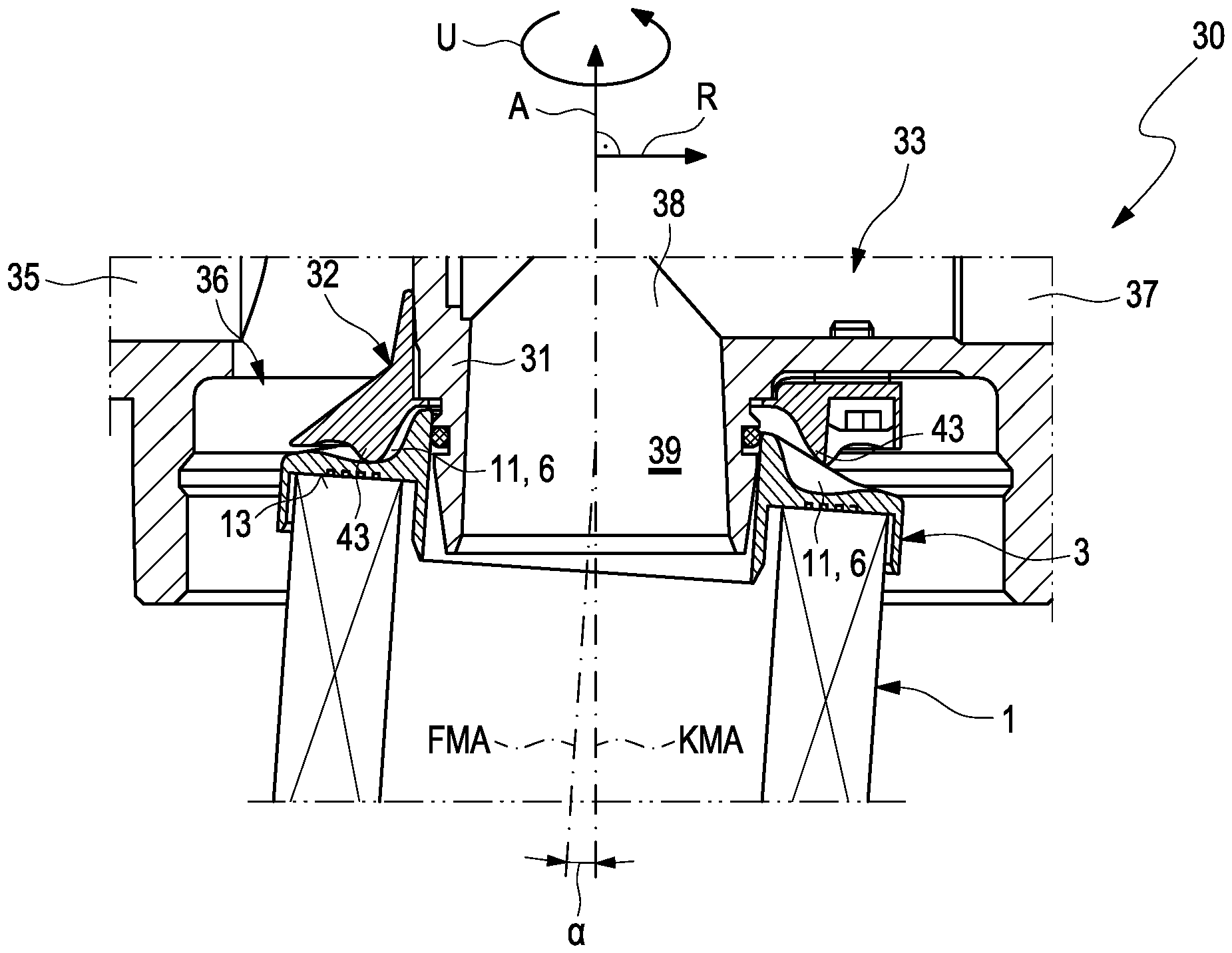
Die
Die Filtereinrichtung 30 umfasst ferner ein Gehäuse 34, das lösbar an der Konsole 33 befestigt ist und einen Aufnahmeraum 39 enthält. Das Gehäuse 34 schließt im zusammengebauten Zustand der Filtereinrichtung 30 nach unten an die Konsole 33 an, sodass sich der Aufnahmeraum 39 unterhalb der Konsole 33 befindet.The
Der Ablauf der Filtereinrichtung 30 weist an der Konsole 33 einen Aufnahmestutzen 31 auf, der die Ablauföffnung 38 umfasst und der im Beispielszenario außerdem konzentrisch zur Konsole-Mittellängsachse KMA angeordnet ist. Weiterhin umfasst die Filtereinrichtung 30 ein erfindungsgemäßes Filterelement 1. Der Aufnahmestutzen 31 durchsetzt eine zentrale Scheibenöffnung 5 einer ringförmigen oberen Endscheibe 3 des Filterelements 1. Das Filterelement 1 ist austauschbar im Aufnahmeraum 39 der Filtereinrichtung 30 angeordnet und trennt im Aufnahmeraum 39 eine mit dem Zulauf 35 fluidisch verbundene Rohseite 16 von einer mit dem Ablauf 37 fluidisch verbundenen Reinseite 17. Gemäß
Die
Wie
Die gemäß
Gemäß
Im Folgenden wird wieder auf die Darstellung der
In dem in
Demgegenüber zeigt die
Die zu einem Verdrehen bzw. Verkippen des Filterelements 1 gegenüber der Konsole 33 erforderliche Ausgestaltung der Endscheiben-Rippenstruktur 6 mit den Rippen 8 und der Endscheiben-Halterung 32 mit den Halterungsrippen 43 wird im Folgenden anhand der
Die
In der in
Außerdem weist in dem in
Um die zum Verkippen erforderliche Drehbewegung durchführen zu können, ist gemäß
Zudem ist von Bedeutung, dass im radial äußersten Bereich zwischen Unterseite 42 der Endscheiben-Halterung und der Oberseite der offenen Endscheibe ein Spalt besteht. Dieser Spalt „d“ wird benötigt, um den Freiheitsgrad für das Kippen des Filterelementes um den Drehpunkt D zu schaffen. Dieser Spalt ermöglicht das Kippen des Filterelementes, da sich die offene Endscheibe in
Im Folgenden wird auf
Gemäß
Eine von der Oberseite 46 des Grundkörpers 40 abgewandte Unterseite 51 der Vertiefung 50 weist eine Kontur 52 auf, deren axialer Abstand d zur Körperebene KE des Grundkörpers 40 von radial innen nach radial außen zunimmt. Auch die anhand der
Claims (12)
Priority Applications (2)
| Application Number | Priority Date | Filing Date | Title |
|---|---|---|---|
| DE102022209325.9A DE102022209325B4 (en) | 2022-09-07 | 2022-09-07 | filter element and filter device |
| EP23195778.8A EP4335532B1 (en) | 2022-09-07 | 2023-09-06 | Filter element and filter device |
Applications Claiming Priority (1)
| Application Number | Priority Date | Filing Date | Title |
|---|---|---|---|
| DE102022209325.9A DE102022209325B4 (en) | 2022-09-07 | 2022-09-07 | filter element and filter device |
Publications (2)
| Publication Number | Publication Date |
|---|---|
| DE102022209325A1 DE102022209325A1 (en) | 2024-03-07 |
| DE102022209325B4 true DE102022209325B4 (en) | 2025-01-16 |
Family
ID=87933547
Family Applications (1)
| Application Number | Title | Priority Date | Filing Date |
|---|---|---|---|
| DE102022209325.9A Active DE102022209325B4 (en) | 2022-09-07 | 2022-09-07 | filter element and filter device |
Country Status (2)
| Country | Link |
|---|---|
| EP (1) | EP4335532B1 (en) |
| DE (1) | DE102022209325B4 (en) |
Families Citing this family (2)
| Publication number | Priority date | Publication date | Assignee | Title |
|---|---|---|---|---|
| EP4650029B1 (en) | 2024-05-17 | 2026-01-28 | Donaldson Company, Inc. | Filter elements and assemblies |
| US12434181B1 (en) | 2024-11-01 | 2025-10-07 | Donaldson Company, Inc. | Air cleaner and filtration assemblies |
Citations (7)
| Publication number | Priority date | Publication date | Assignee | Title |
|---|---|---|---|---|
| DE112008002400T5 (en) | 2007-09-05 | 2010-08-05 | Cummins Filtration IP, Inc., Minneapolis | Replaceable filter elements including unique interfaces and filtration systems that include the same |
| DE102010005978A1 (en) | 2010-01-28 | 2011-08-18 | MAHLE International GmbH, 70376 | Filter device for filtering fluid, lubricant or hydraulic fluid, has filter housing that is provided with inlet that is provided opposite to one of two end disks, where flow guidance device is provided at end disk of ring filter elements |
| DE112013002042T5 (en) | 2012-06-12 | 2015-03-05 | Cummins Filtration Ip, Inc. | Inlet and outlet flow paths forming filter element end plate |
| DE102015003604A1 (en) | 2015-03-19 | 2016-09-22 | Hydac Filtertechnik Gmbh | filter means |
| DE102015005136A1 (en) | 2015-04-22 | 2016-10-27 | Hydac Filtertechnik Gmbh | filter means |
| EP2621601B1 (en) | 2010-10-01 | 2019-05-08 | Caterpillar INC. | Fluid filter system |
| DE112018003574T5 (en) | 2017-07-12 | 2020-03-26 | Cummins Filtration Ip, Inc. | Fuel-water separator systems and processes |
Family Cites Families (3)
| Publication number | Priority date | Publication date | Assignee | Title |
|---|---|---|---|---|
| CA1080130A (en) * | 1976-03-30 | 1980-06-24 | Pall Corporation | Pharmaceutical filter |
| US6006924A (en) * | 1997-05-14 | 1999-12-28 | Pti Technologies, Inc. | Multi-media filtration system with reusable and demountable filter cartridge |
| IN2014MN01634A (en) * | 2012-02-13 | 2015-05-15 | Clarcor Engine Mobile Solutions Llc |
-
2022
- 2022-09-07 DE DE102022209325.9A patent/DE102022209325B4/en active Active
-
2023
- 2023-09-06 EP EP23195778.8A patent/EP4335532B1/en active Active
Patent Citations (7)
| Publication number | Priority date | Publication date | Assignee | Title |
|---|---|---|---|---|
| DE112008002400T5 (en) | 2007-09-05 | 2010-08-05 | Cummins Filtration IP, Inc., Minneapolis | Replaceable filter elements including unique interfaces and filtration systems that include the same |
| DE102010005978A1 (en) | 2010-01-28 | 2011-08-18 | MAHLE International GmbH, 70376 | Filter device for filtering fluid, lubricant or hydraulic fluid, has filter housing that is provided with inlet that is provided opposite to one of two end disks, where flow guidance device is provided at end disk of ring filter elements |
| EP2621601B1 (en) | 2010-10-01 | 2019-05-08 | Caterpillar INC. | Fluid filter system |
| DE112013002042T5 (en) | 2012-06-12 | 2015-03-05 | Cummins Filtration Ip, Inc. | Inlet and outlet flow paths forming filter element end plate |
| DE102015003604A1 (en) | 2015-03-19 | 2016-09-22 | Hydac Filtertechnik Gmbh | filter means |
| DE102015005136A1 (en) | 2015-04-22 | 2016-10-27 | Hydac Filtertechnik Gmbh | filter means |
| DE112018003574T5 (en) | 2017-07-12 | 2020-03-26 | Cummins Filtration Ip, Inc. | Fuel-water separator systems and processes |
Also Published As
| Publication number | Publication date |
|---|---|
| EP4335532B1 (en) | 2025-08-06 |
| DE102022209325A1 (en) | 2024-03-07 |
| EP4335532C0 (en) | 2025-08-06 |
| EP4335532A1 (en) | 2024-03-13 |
Similar Documents
| Publication | Publication Date | Title |
|---|---|---|
| EP2490784B1 (en) | Filter device and filter element for use with such a filter device | |
| DE102009048412B3 (en) | Filter system for filtration of e.g. diesel in motor vehicle, has safety device, and elastic safety-spring element located in bowl when edge-track section is arranged at head or located at head when edge section is arranged in bowl | |
| EP2054133B1 (en) | Liquid filter, particularly for motor vehicles | |
| EP3268106B1 (en) | Filter having a filter bypass valve, and filter cartridge therefor | |
| EP2445604B1 (en) | Filter device | |
| DE102022209325B4 (en) | filter element and filter device | |
| EP2283910B1 (en) | Fluid filter, in particular oil filter | |
| DE602004008998T2 (en) | Valve body and valve supplied with it | |
| DE1935764B2 (en) | Liquid filter unit | |
| DE112015001643T5 (en) | Natural gas filter with snap-in function | |
| DE102010035465A1 (en) | Filter for filtration of fluids, filter bowl and filter head | |
| EP2229232A1 (en) | Fluid filter | |
| DE112008002287T5 (en) | filter cartridge | |
| EP3972713B1 (en) | Filter apparatus | |
| EP1866051B1 (en) | Oil filter arrangement | |
| DE2528932C2 (en) | Filter arrangement | |
| DE102009043638A1 (en) | High pressure filter device | |
| EP4088801B1 (en) | Filter device | |
| EP4146366B1 (en) | Filter apparatus | |
| DE602004012297T2 (en) | RE-WASHABLE FILTER WITH SPOILER CLEANING | |
| EP4171781B1 (en) | Filter device having a filter element | |
| DE29706863U1 (en) | Jet pipe for descaling steel sheets or the like. | |
| DE2308568A1 (en) | FLUID FLOW CONTROL VALVE | |
| DE102021209336B4 (en) | Filter device for filtering a liquid and associated filter element | |
| EP3544714B1 (en) | Filter element and fluid filter comprising a rotatable bayonet ring |
Legal Events
| Date | Code | Title | Description |
|---|---|---|---|
| R012 | Request for examination validly filed | ||
| R016 | Response to examination communication | ||
| R016 | Response to examination communication | ||
| R018 | Grant decision by examination section/examining division | ||
| R020 | Patent grant now final |