DE102021112547A1 - Procedure for determining a registry error - Google Patents
Procedure for determining a registry error Download PDFInfo
- Publication number
- DE102021112547A1 DE102021112547A1 DE102021112547.2A DE102021112547A DE102021112547A1 DE 102021112547 A1 DE102021112547 A1 DE 102021112547A1 DE 102021112547 A DE102021112547 A DE 102021112547A DE 102021112547 A1 DE102021112547 A1 DE 102021112547A1
- Authority
- DE
- Germany
- Prior art keywords
- contour
- registration
- contours
- image
- procedure
- Prior art date
- Legal status (The legal status is an assumption and is not a legal conclusion. Google has not performed a legal analysis and makes no representation as to the accuracy of the status listed.)
- Pending
Links
Images


Classifications
-
- G—PHYSICS
- G03—PHOTOGRAPHY; CINEMATOGRAPHY; ANALOGOUS TECHNIQUES USING WAVES OTHER THAN OPTICAL WAVES; ELECTROGRAPHY; HOLOGRAPHY
- G03F—PHOTOMECHANICAL PRODUCTION OF TEXTURED OR PATTERNED SURFACES, e.g. FOR PRINTING, FOR PROCESSING OF SEMICONDUCTOR DEVICES; MATERIALS THEREFOR; ORIGINALS THEREFOR; APPARATUS SPECIALLY ADAPTED THEREFOR
- G03F7/00—Photomechanical, e.g. photolithographic, production of textured or patterned surfaces, e.g. printing surfaces; Materials therefor, e.g. comprising photoresists; Apparatus specially adapted therefor
- G03F7/70—Microphotolithographic exposure; Apparatus therefor
- G03F7/70483—Information management; Active and passive control; Testing; Wafer monitoring, e.g. pattern monitoring
- G03F7/70605—Workpiece metrology
- G03F7/70616—Monitoring the printed patterns
- G03F7/70633—Overlay, i.e. relative alignment between patterns printed by separate exposures in different layers, or in the same layer in multiple exposures or stitching
-
- G—PHYSICS
- G03—PHOTOGRAPHY; CINEMATOGRAPHY; ANALOGOUS TECHNIQUES USING WAVES OTHER THAN OPTICAL WAVES; ELECTROGRAPHY; HOLOGRAPHY
- G03F—PHOTOMECHANICAL PRODUCTION OF TEXTURED OR PATTERNED SURFACES, e.g. FOR PRINTING, FOR PROCESSING OF SEMICONDUCTOR DEVICES; MATERIALS THEREFOR; ORIGINALS THEREFOR; APPARATUS SPECIALLY ADAPTED THEREFOR
- G03F1/00—Originals for photomechanical production of textured or patterned surfaces, e.g., masks, photo-masks, reticles; Mask blanks or pellicles therefor; Containers specially adapted therefor; Preparation thereof
- G03F1/68—Preparation processes not covered by groups G03F1/20 - G03F1/50
- G03F1/82—Auxiliary processes, e.g. cleaning or inspecting
- G03F1/84—Inspecting
-
- G—PHYSICS
- G03—PHOTOGRAPHY; CINEMATOGRAPHY; ANALOGOUS TECHNIQUES USING WAVES OTHER THAN OPTICAL WAVES; ELECTROGRAPHY; HOLOGRAPHY
- G03F—PHOTOMECHANICAL PRODUCTION OF TEXTURED OR PATTERNED SURFACES, e.g. FOR PRINTING, FOR PROCESSING OF SEMICONDUCTOR DEVICES; MATERIALS THEREFOR; ORIGINALS THEREFOR; APPARATUS SPECIALLY ADAPTED THEREFOR
- G03F1/00—Originals for photomechanical production of textured or patterned surfaces, e.g., masks, photo-masks, reticles; Mask blanks or pellicles therefor; Containers specially adapted therefor; Preparation thereof
- G03F1/68—Preparation processes not covered by groups G03F1/20 - G03F1/50
- G03F1/72—Repair or correction of mask defects
-
- G—PHYSICS
- G03—PHOTOGRAPHY; CINEMATOGRAPHY; ANALOGOUS TECHNIQUES USING WAVES OTHER THAN OPTICAL WAVES; ELECTROGRAPHY; HOLOGRAPHY
- G03F—PHOTOMECHANICAL PRODUCTION OF TEXTURED OR PATTERNED SURFACES, e.g. FOR PRINTING, FOR PROCESSING OF SEMICONDUCTOR DEVICES; MATERIALS THEREFOR; ORIGINALS THEREFOR; APPARATUS SPECIALLY ADAPTED THEREFOR
- G03F9/00—Registration or positioning of originals, masks, frames, photographic sheets or textured or patterned surfaces, e.g. automatically
- G03F9/70—Registration or positioning of originals, masks, frames, photographic sheets or textured or patterned surfaces, e.g. automatically for microlithography
- G03F9/7003—Alignment type or strategy, e.g. leveling, global alignment
-
- G—PHYSICS
- G03—PHOTOGRAPHY; CINEMATOGRAPHY; ANALOGOUS TECHNIQUES USING WAVES OTHER THAN OPTICAL WAVES; ELECTROGRAPHY; HOLOGRAPHY
- G03F—PHOTOMECHANICAL PRODUCTION OF TEXTURED OR PATTERNED SURFACES, e.g. FOR PRINTING, FOR PROCESSING OF SEMICONDUCTOR DEVICES; MATERIALS THEREFOR; ORIGINALS THEREFOR; APPARATUS SPECIALLY ADAPTED THEREFOR
- G03F9/00—Registration or positioning of originals, masks, frames, photographic sheets or textured or patterned surfaces, e.g. automatically
- G03F9/70—Registration or positioning of originals, masks, frames, photographic sheets or textured or patterned surfaces, e.g. automatically for microlithography
- G03F9/7088—Alignment mark detection, e.g. TTR, TTL, off-axis detection, array detector, video detection
-
- G—PHYSICS
- G06—COMPUTING OR CALCULATING; COUNTING
- G06T—IMAGE DATA PROCESSING OR GENERATION, IN GENERAL
- G06T7/00—Image analysis
- G06T7/0002—Inspection of images, e.g. flaw detection
- G06T7/0004—Industrial image inspection
-
- G—PHYSICS
- G06—COMPUTING OR CALCULATING; COUNTING
- G06T—IMAGE DATA PROCESSING OR GENERATION, IN GENERAL
- G06T7/00—Image analysis
- G06T7/0002—Inspection of images, e.g. flaw detection
- G06T7/0004—Industrial image inspection
- G06T7/001—Industrial image inspection using an image reference approach
-
- G—PHYSICS
- G06—COMPUTING OR CALCULATING; COUNTING
- G06T—IMAGE DATA PROCESSING OR GENERATION, IN GENERAL
- G06T7/00—Image analysis
- G06T7/10—Segmentation; Edge detection
- G06T7/11—Region-based segmentation
-
- G—PHYSICS
- G06—COMPUTING OR CALCULATING; COUNTING
- G06T—IMAGE DATA PROCESSING OR GENERATION, IN GENERAL
- G06T2207/00—Indexing scheme for image analysis or image enhancement
- G06T2207/10—Image acquisition modality
-
- G—PHYSICS
- G06—COMPUTING OR CALCULATING; COUNTING
- G06T—IMAGE DATA PROCESSING OR GENERATION, IN GENERAL
- G06T2207/00—Indexing scheme for image analysis or image enhancement
- G06T2207/10—Image acquisition modality
- G06T2207/10056—Microscopic image
-
- G—PHYSICS
- G06—COMPUTING OR CALCULATING; COUNTING
- G06T—IMAGE DATA PROCESSING OR GENERATION, IN GENERAL
- G06T2207/00—Indexing scheme for image analysis or image enhancement
- G06T2207/20—Special algorithmic details
- G06T2207/20112—Image segmentation details
- G06T2207/20116—Active contour; Active surface; Snakes
-
- G—PHYSICS
- G06—COMPUTING OR CALCULATING; COUNTING
- G06T—IMAGE DATA PROCESSING OR GENERATION, IN GENERAL
- G06T2207/00—Indexing scheme for image analysis or image enhancement
- G06T2207/30—Subject of image; Context of image processing
- G06T2207/30108—Industrial image inspection
- G06T2207/30148—Semiconductor; IC; Wafer
Landscapes
- Engineering & Computer Science (AREA)
- Physics & Mathematics (AREA)
- General Physics & Mathematics (AREA)
- Computer Vision & Pattern Recognition (AREA)
- Theoretical Computer Science (AREA)
- Quality & Reliability (AREA)
- Multimedia (AREA)
- Preparing Plates And Mask In Photomechanical Process (AREA)
- Exposure And Positioning Against Photoresist Photosensitive Materials (AREA)
- Image Analysis (AREA)
Abstract
Die Erfindung betrifft ein Verfahren zur Ermittlung eines Registrierungsfehlers einer Struktur auf einer Maske für die Halbleiterlithographie, umfassend folgende Verfahrensschritte:
- Erzeugung eines Abbildes mindestens eines Bereiches der Maske,
- Bestimmung mindestens einer Messkontur im Abbild,
- Angleichung der Formen einer Designkontur und einer Messkontur an einander bei gleichzeitiger Angleichung der Registrierung der beiden Konturen.
- generation of an image of at least one area of the mask,
- determination of at least one measurement contour in the image,
- Matching the shapes of a design contour and a measurement contour to each other while matching the registration of the two contours.
Description
Die Erfindung betrifft ein Verfahren zur Ermittlung eines Registrierungsfehlers einer Maske für die Halbleiterlithographie.The invention relates to a method for determining a registration error in a mask for semiconductor lithography.
Photolithographische Masken werden in Lithographiesystemen oder zum Herstellen mikrostrukturierter Bauelemente, wie etwa integrierter Schaltkreise oder LCDs (Liquid Crystal Displays) eingesetzt. In einem Lithographieprozess oder einem Mikrolithographieprozess beleuchtet dabei eine Beleuchtungseinheit eine photolithographische Maske, welche auch als Photomaske oder einfach Maske bezeichnet wird. Das durch die Maske hindurchtretende Licht oder das von der Maske reflektierte Licht wird von einer Projektionsoptik auf ein mit einer lichtempfindlichen Schicht (Photoresist) beschichtetes, in der Bildebene der Projektionsoptik angebrachtes Substrat (beispielsweise einen Wafer) projiziert, um die Strukturelemente der Maske auf die lichtempfindliche Beschichtung des Substrats zu übertragen und so eine gewünschte Struktur auf dem Substrat zu erzeugen.Photolithographic masks are used in lithography systems or to produce microstructured components such as integrated circuits or LCDs (Liquid Crystal Displays). In a lithographic process or a microlithographic process, an illumination unit illuminates a photolithographic mask, which is also referred to as a photomask or simply a mask. The light passing through the mask or the light reflected by the mask is projected by projection optics onto a substrate (e.g. a wafer) coated with a light-sensitive layer (photoresist) and mounted in the image plane of the projection optics, in order to project the structural elements of the mask onto the light-sensitive To transfer coating of the substrate and so to produce a desired structure on the substrate.
Die Platzierung von Strukturelementen auf der Oberfläche von Masken muss hochgenau sein, so dass die zulässige Abweichung von deren vorgegebenen Positionen - der sogenannte Registrierungsfehler - vorzugsweise im Subnanometerbereich liegt, um nicht zu Fehlern auf Wafern bei der Belichtung mit der entsprechenden Maske zu führen. Die Herstellung von Photomasken, die diese Anforderungen erfüllen können, ist extrem komplex, fehleranfällig und damit teuer.The placement of structure elements on the surface of masks must be extremely precise, so that the permissible deviation from their specified positions - the so-called registration error - is preferably in the sub-nanometer range in order not to lead to errors on wafers during exposure with the corresponding mask. The production of photomasks that can meet these requirements is extremely complex, error-prone and therefore expensive.
Zur Ermittlung des Registrierungsfehlers werden Maskeninspektionsmikroskope, Elektronenmikroskope oder Positionsbestimmungsvorrichtungen eingesetzt. Die Strukturen werden über üblicherweise über eine Kantendetektion detektiert. Zur Charakterisierung der Strukturen werden üblicherweise drei Methoden verwendet. Mask inspection microscopes, electron microscopes or position determination devices are used to determine the registration error. The structures are usually detected by edge detection. Three methods are commonly used to characterize the structures.
Die Schwellwert-Methode (engl.: Threshold), bei der die Position der Struktur durch die Ermittlung eines Schnittpunktes der über einen Intensitätsschwellwert erfassten Kante und einer Mess- oder Bezugsebene, die senkrecht zur Struktur verläuft, bestimmt wird.The threshold method, in which the position of the structure is determined by finding an intersection of the edge detected via an intensity threshold and a measurement or reference plane that is perpendicular to the structure.
Die Korrelationsmethode, bei der die Position der Struktur durch eine Korrelation des mit der Positionsbestimmungsvorrichtung erfassten Luftbildes und eines simulierten Luftbildes bestimmt wird. Die Form der mit der Positionsbestimmungsvorrichtung in einem Luftbild erfassten Struktur und der simulierten Struktur wird aneinander angepasst und in einem zweiten Schritt der Abstand zwischen den beiden Strukturen bestimmt. Dieser Abstand entspricht der Abweichung der mit dem Luftbild erfassten Struktur von der Sollposition.The correlation method, in which the position of the structure is determined by correlating the aerial image captured by the positioning device and a simulated aerial image. The shape of the structure recorded in an aerial image using the position determination device and the simulated structure are matched to one another and, in a second step, the distance between the two structures is determined. This distance corresponds to the deviation of the structure recorded with the aerial photo from the target position.
Die Symmetrie-Korrelationsmethode, die in der deutschen Patentanmeldung
Diese Methoden haben den Nachteil, dass eine unbekannte Verdrehung der zu erfassenden Strukturen im Bildfeld bei den ersten beiden Methoden zu verfälschten Methoden führen kann. Weiterhin führen Fehler der Bildintensität abseits der zu erfassenden Strukturen, die eigentlich irrelevant sind, fallen bei den letzten beiden Methoden ins Gewicht und können somit zu verfälschten Messergebnissen führen.These methods have the disadvantage that an unknown rotation of the structures to be recorded in the image field can lead to incorrect methods in the first two methods. Furthermore, errors in the image intensity apart from the structures to be recorded, which are actually irrelevant, are significant in the last two methods and can therefore lead to falsified measurement results.
Aufgabe der vorliegenden Erfindung ist es, ein verbessertes Verfahren anzugeben, welches die oben beschriebenen Nachteile des Standes der Technik beseitigt.The object of the present invention is to specify an improved method which eliminates the disadvantages of the prior art described above.
Diese Aufgabe wird gelöst durch ein Verfahren mit den Merkmalen des unabhängigen Anspruchs. Die Unteransprüche betreffen vorteilhafte Weiterbildungen und Varianten der Erfindung.This object is achieved by a method having the features of the independent claim. The dependent claims relate to advantageous developments and variants of the invention.
Ein erfindungsgemäßes Verfahren zur Ermittlung eines Registrierungsfehlers einer Struktur auf einer Maske für die Halbleiterlithographie umfasst folgende Verfahrensschritte:
- - Erzeugung eines Abbildes mindestens eines Bereiches der Maske,
- - Bestimmung mindestens einer Messkontur im Abbild,
- - Angleichung der Formen einer Designkontur und einer Messkontur an einander bei gleichzeitiger Angleichung der Registrierung der beiden Konturen.
- - generation of an image of at least one area of the mask,
- - determination of at least one measurement contour in the image,
- - Matching the shapes of a design contour and a measurement contour to each other while matching the registration of the two contours.
Mit anderen Worten werden Form und Registrierung derart angepasst, dass ein minimaler mittlerer lateraler Abstand zwischen der Mess- und der Designkontur erreicht wird.In other words, shape and registration are adjusted in such a way that a minimum mean lateral distance between the measurement and the design contour is achieved.
Bei den Messkonturen handelt es sich um Konturen, die aus dem Abbild extrahiert wurden Unter den Designkonturen versteht man die Konturen, wie sie beispielsweise in einem Maskenschreiber zur Fertigung bzw. Schaffung der Strukturen auf einer Maske zur Verfügung gestellt werden. Erfindungsgemäß wird vorteilhaft gemeinsam Form und Registrierung von Strukturen optimiert beziehungsweise angeglichen.The measurement contours are contours that were extracted from the image. The design contours are the contours that are made available, for example, in a mask writer for manufacturing or creating the structures on a mask. According to the invention, the shape and registration of structures are advantageously optimized or adjusted together.
Die Registrierung kann insbesondere durch die Minimierung der mittleren lateralen Abstände der beiden Konturen in der Maskenebene minimiert werden. Es erfolgt also nicht eine Korrelation anhand von Intensitätswerten, sondern es werden laterale Abstände zwischen Messung und Design betrachtet. Der Vorteil bei dieser Variante besteht insbesondere darin, dass Fehler, die aus einer Verdrehung von Messbild gegenüber Designbild stammen, zuverlässig erkannt und berücksichtigt werden können, so dass eine Verdrehung den ermittelten Registrierungsfehler im Hinblick auf die Genauigkeit der Ermittlung nicht verschlechtert. Grundsätzlich ist es auch denkbar, Form und Lage der Strukturen gemeinsam zu optimieren, aber an Stelle der lateralen Abstände auch die Intensitäten als Optimierungskriterium heranzuziehen; Ebenso könnten auch Form und Lage sequentiell optimiert bzw. angeglichen werden und die lateralen Abstände als Optimierungskriterium heranzuziehen.The registration can be minimized in particular by minimizing the mean lateral distances between the two contours in the mask plane. There is therefore no correlation based on of intensity values, but lateral distances between measurement and design are considered. The advantage of this variant is, in particular, that errors resulting from a rotation of the measurement image relative to the design image can be reliably detected and taken into account, so that a rotation does not worsen the registration error determined with regard to the accuracy of the determination. In principle, it is also conceivable to optimize the shape and position of the structures together, but also to use the intensities as an optimization criterion instead of the lateral distances; Likewise, the shape and position could also be sequentially optimized or adjusted and the lateral distances could be used as an optimization criterion.
Die Angleichung der Formen der Konturen kann durch eine Modifikation der Designkontur bewirkt werden, ebenso kann die Angleichung der Formen der Konturen durch eine Modifikation der Messkontur oder durch eine Kombination beider Verfahren bewirkt werden.The shapes of the contours can be adjusted by modifying the design contour, the shapes of the contours can also be adjusted by modifying the measurement contour or by a combination of both methods.
In einer vorteilhaften Variante der Erfindung können als Maß für die Qualität der Angleichung Differenzen bei der Überlagerung der Mess- und der Designkontur herangezogen werden. Diese Differenzen werden auch als Residuen bezeichnet. Die Residuen sollen möglichst minimiert werden und können sich insbesondere aus a) den kürzesten Abständen aller Messkonturpunkte zur Designkonturlinie oder b) den kürzesten Abständen aller Designkonturpunkte zur Messkonturlinie oder c) der Gesamtmenge aus a) und b) ergeben. Es werden also anstelle von Intensitätsdifferenzen wie aus dem Stand der Technik bekannt, laterale Abstände betrachtet. Optimierungsverfahren sind prinzipiell viele denkbar. So kann beispielsweise ein mehrdimensionales Newton-Verfahren zu einer Minimierung der Abstände zwischen Mess- und Designkontur verwendet werden. Derartige Verfahren sind vergleichsweise robust und ermitteln die optimalen Parameter zur Angleichung von Form und Registrierung unter Verwendung der Least-Square-Methode.In an advantageous variant of the invention, differences in the superimposition of the measurement contour and the design contour can be used as a measure of the quality of the adjustment. These differences are also referred to as residuals. The residuals should be minimized as far as possible and can result in particular from a) the shortest distances of all measurement contour points to the design contour line or b) the shortest distances of all design contour points to the measurement contour line or c) the total of a) and b). Thus, instead of intensity differences, as is known from the prior art, lateral distances are considered. In principle, many optimization methods are conceivable. For example, a multidimensional Newton method can be used to minimize the distances between the measurement and design contours. Such methods are comparatively robust and determine the optimal parameters for matching shape and registration using the least squares method.
In einer vorteilhaften Ausführungsform der Erfindung kann der Mittelwert aller Abstände zwischen Mess- und Designkontur als Maß für den Optimierungsfortschritt verwendet werden. Dieser auch als MeanResid bezeichnete Zahlenwert stellt ein gutes Maß für den Fortschritt der Iterationen bei der Angleichung dar. Sobald sich dieser Wert zwischen zwei Iterationen nur noch unterhalb eines vorher festgelegten Maximalwertes stagniert, kann die Optimierung beendet werden.In an advantageous embodiment of the invention, the mean value of all distances between the measurement and design contours can be used as a measure of the optimization progress. This numerical value, also known as MeanResid, represents a good measure of the progress of the iterations during the adjustment. As soon as this value stagnates between two iterations below a previously specified maximum value, the optimization can be ended.
Die Angleichung kann auch für einzelne Teilbereiche des Abbildes erfolgen. Dabei können insbesondere separate Parameter für einzelne Bildbereiche bis hin zu separaten Parametern für einzelne Teilstrukturen, sogenannte Features, angepasst werden. Auch Mischformen sind denkbar, beispielsweise Mischungen aus globaler und lokaler Modifikation der Registrierung und/oder Mischungen aus globaler und lokaler Modifikation der Form.The adjustment can also be made for individual sub-areas of the image. In particular, separate parameters for individual image areas through to separate parameters for individual substructures, so-called features, can be adjusted. Mixed forms are also conceivable, for example mixtures of global and local modification of the registration and/or mixtures of global and local modification of the form.
Es kann ebenso von Vorteil sein, bestimmte Bereiche des Abbildes nicht zur Angleichung zu verwenden. Hierfür kommen insbesondere Bereiche in Frage, in welchen Defekte erkannt wurden.It can also be advantageous not to use certain areas of the image for matching. Areas in which defects were detected are particularly suitable for this purpose.
Weiterhin kann eine alternierende, also abwechselnde Modifikation der Formen und der Registrierung vorgenommen werden.Furthermore, an alternating, i.e. alternating, modification of the forms and the registration can be made.
Nachfolgend werden Ausführungsbeispiele und Varianten der Erfindung anhand der Zeichnung näher erläutert. Es zeigen
-
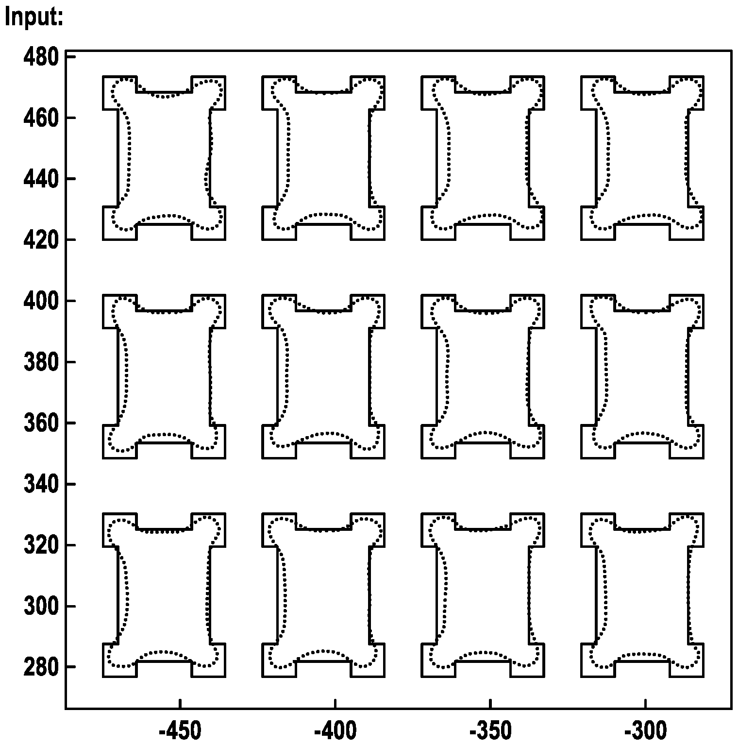
1 eine exemplarische Darstellung der Ausgangslage, -
2 die exemplarische Entwicklung von zur Angleichung verwendeten Parametern, -
3 das Ergebnis der Angleichung, und -
4 das Ergebnis der Angleichung mit einer defekten Struktur.
-
1 an exemplary representation of the initial situation, -
2 the exemplary development of parameters used for the adjustment, -
3 the result of the alignment, and -
4 the result of alignment with a defective structure.
Im Einzelnen:
- Registrierungsparameter:
- 1. TranslationX: Verschiebung der Konturen in x-Richtung (0. Ordnung)
- 2. TranslationY: Verschiebung der Konturen in y Richtung (0. Ordnung)
- 3. Scale: Maßstäbliche Streckung der Kontur um einen Ursprung (1. Ordnung)
- 4. Rotation: Drehung der Kontur um einen Ursprung (1. Ordnung)
- Registration parameters:
- 1. TranslationX: Shift of the contours in the x-direction (0th order)
- 2. TranslationY: Shift of the contours in the y direction (0th order)
- 3. Scale: True-to-scale stretching of the contour around an origin (1st order)
- 4. Rotation: rotation of the contour around an origin (1st order)
Weitere denkbare Parameter für die Optimierung der Angleichung sind der asymmetrische Maßstab und die asymmetrische Rotation, die im gezeigten Beispiel jedoch nicht zur Anwendung kommen. Weiterhin können die Parameter erster Ordnung auch in ScaleX, ScaleY, Rotation X und Rotation Y umgerechnet werden.Other conceivable parameters for optimizing the adjustment are the asymmetric scale and the asymmetric rotation, which are not used in the example shown. Furthermore, the parameters of the first order can also be converted into ScaleX, ScaleY, Rotation X and Rotation Y.
Im gezeigten Beispiel wurden die genannten Registrierungsparameter auf die Messkontur angewendet. Es ist auch denkbar die Registrierungsparameter auf die Designkontur anzuwenden; ferner ist auch eine kombinierte Anwendung auf Mess- und Designkontur denkbar, dabei ist jedoch zu beachten, dass es bei dieser Variante zu keinen unerwünschten Redundanzen und damit zu einer nichtgewollten Abhängigkeit der Parameter untereinander kommt.In the example shown, the registration parameters mentioned were applied to the measurement contour. It is also conceivable to apply the registration parameters to the design contour; Furthermore, a combined application to measurement and design contours is also conceivable, but it should be noted that with this variant there are no undesired redundancies and thus an unwanted dependence of the parameters on one another.
Die Formparameter (erste 3 Graphen der unteren Reihe) dienen dazu, die Form der Konturen zu verändern, um das Erscheinungsbild von Mess- und Designkontur anzugleichen. Für die gezeigte Variante wurden die nachfolgend beschriebenen Formparameter verwendet (es sind auch andere Formparameter denkbar):
- 1. Sigma ist die Breite einer Gaussfilterung, mittels welcher ein aus der Designkontur erstelltes Objekt gefiltert wird.
- 2. Thresh ist derjenige Funktionswert des gaussgefilterten Objektes, aus welchem eine neue Designkontur berechnet wird.
- 3. Bias ist derjenige Wert, um welchen die in 2. neuberechnete Designkontur in Normalenrichtung verschoben wird.
- 1. Sigma is the width of a Gaussian filter used to filter an object created from the design contour.
- 2. Thresh is the function value of the Gaussian-filtered object from which a new design contour is calculated.
- 3. Bias is the value by which the design contour recalculated in 2. is shifted in the normal direction.
Auch die Formparameter können entweder auf die Messkontur oder auf der Designkontur (wie im gezeigten Beispiel), oder auch kombiniert bzw. aufgeteilt angewendet werden.The shape parameters can either be applied to the measurement contour or to the design contour (as in the example shown), or combined or divided.
Der 4. Graph der unteren Reihe zeigt das bereits vorne erwähnte, MeanResid genannte Optimierungskriterium. Gut erkennbar in der Figur ist, dass der Wert für MeanResid ab der 3. Iteration zu stagnieren beginnt, in diesem Fall kann die Angleichung beendet werden.The 4th graph in the bottom row shows the MeanResid optimization criterion already mentioned above. The figure clearly shows that the value for MeanResid begins to stagnate from the 3rd iteration, in which case the adjustment can be terminated.
Grundsätzlich ist darauf zu achten, dass die Optimierungsparameter linear unabhängig voneinander gewählt werden und eine Wirkung auf das Signal erzeugen. Es macht beispielsweise keinen Sinn, eine Translation in X Richtung ermitteln zu wollen, wenn sich im Bild aus-schließlich in X Richtung verlaufende Linien befinden.In principle, care must be taken to ensure that the optimization parameters are chosen linearly independently of one another and produce an effect on the signal. It makes no sense, for example, to want to determine a translation in the X direction if there are only lines running in the X direction in the image.
ZITATE ENTHALTEN IN DER BESCHREIBUNGQUOTES INCLUDED IN DESCRIPTION
Diese Liste der vom Anmelder aufgeführten Dokumente wurde automatisiert erzeugt und ist ausschließlich zur besseren Information des Lesers aufgenommen. Die Liste ist nicht Bestandteil der deutschen Patent- bzw. Gebrauchsmusteranmeldung. Das DPMA übernimmt keinerlei Haftung für etwaige Fehler oder Auslassungen.This list of the documents cited by the applicant was generated automatically and is included solely for the better information of the reader. The list is not part of the German patent or utility model application. The DPMA assumes no liability for any errors or omissions.
Zitierte PatentliteraturPatent Literature Cited
- DE 102010047051 A1 [0007]DE 102010047051 A1 [0007]
Claims (11)
Priority Applications (3)
| Application Number | Priority Date | Filing Date | Title |
|---|---|---|---|
| DE102021112547.2A DE102021112547A1 (en) | 2021-05-14 | 2021-05-14 | Procedure for determining a registry error |
| US17/742,733 US20220365449A1 (en) | 2021-05-14 | 2022-05-12 | Method for determining a registration error |
| JP2022079331A JP7461407B2 (en) | 2021-05-14 | 2022-05-13 | Method for determining alignment error - Patents.com |
Applications Claiming Priority (1)
| Application Number | Priority Date | Filing Date | Title |
|---|---|---|---|
| DE102021112547.2A DE102021112547A1 (en) | 2021-05-14 | 2021-05-14 | Procedure for determining a registry error |
Publications (1)
| Publication Number | Publication Date |
|---|---|
| DE102021112547A1 true DE102021112547A1 (en) | 2022-11-17 |
Family
ID=83806113
Family Applications (1)
| Application Number | Title | Priority Date | Filing Date |
|---|---|---|---|
| DE102021112547.2A Pending DE102021112547A1 (en) | 2021-05-14 | 2021-05-14 | Procedure for determining a registry error |
Country Status (3)
| Country | Link |
|---|---|
| US (1) | US20220365449A1 (en) |
| JP (1) | JP7461407B2 (en) |
| DE (1) | DE102021112547A1 (en) |
Cited By (1)
| Publication number | Priority date | Publication date | Assignee | Title |
|---|---|---|---|---|
| DE102023105762A1 (en) | 2023-03-08 | 2024-03-21 | Carl Zeiss Smt Gmbh | Method and computer program product for identifying defects on photolithographic masks |
Families Citing this family (1)
| Publication number | Priority date | Publication date | Assignee | Title |
|---|---|---|---|---|
| CN119987159B (en) * | 2025-03-13 | 2025-12-05 | 深圳晶源信息技术有限公司 | Methods, apparatus, equipment, media, and products for determining errors in photolithography simulation models. |
Citations (3)
| Publication number | Priority date | Publication date | Assignee | Title |
|---|---|---|---|---|
| DE10044257A1 (en) | 2000-09-07 | 2002-04-11 | Infineon Technologies Ag | Process for generating mask layout data for lithography simulation and optimized mask layout data, and associated device and programs |
| DE10146355A1 (en) | 2001-09-20 | 2003-04-24 | Muetec Automatisierte Mikrosko | Method for the automatic optical measurement of an OPC structure |
| DE102010047051A1 (en) | 2010-09-29 | 2012-03-29 | Carl Zeiss Sms Gmbh | Method for determining the position of a structure within an image and position measuring device for carrying out the method |
Family Cites Families (13)
| Publication number | Priority date | Publication date | Assignee | Title |
|---|---|---|---|---|
| JPH11237344A (en) * | 1998-02-19 | 1999-08-31 | Hitachi Ltd | Defect inspection method and apparatus |
| US6868175B1 (en) * | 1999-08-26 | 2005-03-15 | Nanogeometry Research | Pattern inspection apparatus, pattern inspection method, and recording medium |
| JP3448041B2 (en) * | 2001-09-26 | 2003-09-16 | 株式会社東芝 | Pattern defect inspection equipment |
| JP4999781B2 (en) * | 2002-03-15 | 2012-08-15 | キヤノン株式会社 | Position detection apparatus and method, exposure apparatus, and device manufacturing method |
| JP4165871B2 (en) * | 2002-03-15 | 2008-10-15 | キヤノン株式会社 | Position detection method, position detection apparatus, and exposure apparatus |
| JP3732794B2 (en) * | 2002-03-20 | 2006-01-11 | 株式会社東芝 | Dimensional inspection method and apparatus, and mask manufacturing method |
| JP3806125B2 (en) * | 2004-03-08 | 2006-08-09 | 株式会社東芝 | Defect inspection apparatus and defect inspection method |
| JP4174504B2 (en) * | 2005-08-31 | 2008-11-05 | アドバンスド・マスク・インスペクション・テクノロジー株式会社 | Sample inspection apparatus, sample inspection method, and program |
| JP5604067B2 (en) * | 2009-07-31 | 2014-10-08 | 株式会社日立ハイテクノロジーズ | Matching template creation method and template creation device |
| WO2018077787A1 (en) * | 2016-10-24 | 2018-05-03 | Asml Netherlands B.V. | Method for optimizing a patterning device pattern |
| KR102581877B1 (en) * | 2017-09-27 | 2023-09-25 | 에이에스엠엘 네델란즈 비.브이. | Method of determining control parameters of a device manufacturing process |
| DE102020104167B4 (en) * | 2020-02-18 | 2023-01-26 | Carl Zeiss Smt Gmbh | Process for measuring photomasks |
| KR20220127004A (en) * | 2021-03-10 | 2022-09-19 | 삼성전자주식회사 | A stochastic contour prediction system, a method of providing a stochastic contour prediction system and a method of providing an EUV mask using the stochastic contour prediction system |
-
2021
- 2021-05-14 DE DE102021112547.2A patent/DE102021112547A1/en active Pending
-
2022
- 2022-05-12 US US17/742,733 patent/US20220365449A1/en active Pending
- 2022-05-13 JP JP2022079331A patent/JP7461407B2/en active Active
Patent Citations (3)
| Publication number | Priority date | Publication date | Assignee | Title |
|---|---|---|---|---|
| DE10044257A1 (en) | 2000-09-07 | 2002-04-11 | Infineon Technologies Ag | Process for generating mask layout data for lithography simulation and optimized mask layout data, and associated device and programs |
| DE10146355A1 (en) | 2001-09-20 | 2003-04-24 | Muetec Automatisierte Mikrosko | Method for the automatic optical measurement of an OPC structure |
| DE102010047051A1 (en) | 2010-09-29 | 2012-03-29 | Carl Zeiss Sms Gmbh | Method for determining the position of a structure within an image and position measuring device for carrying out the method |
Cited By (1)
| Publication number | Priority date | Publication date | Assignee | Title |
|---|---|---|---|---|
| DE102023105762A1 (en) | 2023-03-08 | 2024-03-21 | Carl Zeiss Smt Gmbh | Method and computer program product for identifying defects on photolithographic masks |
Also Published As
| Publication number | Publication date |
|---|---|
| JP7461407B2 (en) | 2024-04-03 |
| JP2022176170A (en) | 2022-11-25 |
| US20220365449A1 (en) | 2022-11-17 |
Similar Documents
| Publication | Publication Date | Title |
|---|---|---|
| DE102010025033B4 (en) | Procedure for defect detection and repair of EUV masks | |
| DE102010030758A1 (en) | Control critical dimensions in optical imaging processes for semiconductor fabrication by extracting aberrations based on imaging plant-specific intensity measurements and simulations | |
| DE102013213785A1 (en) | Method and system for determining overlap process windows in semiconductors by inspection techniques | |
| DE102007052052B4 (en) | A method of detecting repeat defects in lithographic masks based on test substrates exposed under varying conditions | |
| DE102017203841B4 (en) | Method and device for determining a repair shape for processing a defect in a photolithographic mask | |
| DE102021112547A1 (en) | Procedure for determining a registry error | |
| DE102006008734A1 (en) | A method for producing a transparent mask blank substrate, method for producing a mask blank and method for producing an exposure mask | |
| DE102015207002B4 (en) | Method for characterizing a diffractive optical structure | |
| DE102013101445B9 (en) | Method for determining distortion properties of an optical system in a measuring device for microlithography | |
| EP3944022B1 (en) | Method and device for characterizing a wafer patterned using at least one lithography step | |
| DE10250845A1 (en) | Method and apparatus for measuring procedural errors and method and apparatus for measuring coverage using the same | |
| DE102021120952B3 (en) | Method for correcting a telecentricity error of an imaging device and mask inspection microscope | |
| DE102017219217B4 (en) | Masks for microlithography, methods for determining edge positions of the images of the structures of such a mask and system for carrying out such a method | |
| DE60218002T2 (en) | Photolithography with multistage substrate | |
| DE102020104167B4 (en) | Process for measuring photomasks | |
| EP1373982B1 (en) | Method for adjusting the overlay of two masking levels in a photolithographic process | |
| DE102013106320B4 (en) | Method for determining distortion properties of an optical system in a measuring device for microlithography | |
| DE10258423B4 (en) | Method for characterizing a lens system | |
| DE102022124800B4 (en) | Method for qualifying a mask of a lithography system | |
| DE10248224A1 (en) | Method for adjusting and exposing a semiconductor wafer | |
| DE102023113273B3 (en) | METHOD AND DEVICE FOR ANALYZING AN IMAGE OF A MICROSTRUCTURED SAMPLE FOR MICROLITHOGRAPHY | |
| DE102007021649A1 (en) | Optical environment effect correcting method for use during reproduction of sample, involves arranging optical units between object surface and image surface, and arranging Fourier-transformed pupil surface on image surface | |
| DE10236422A1 (en) | Method for characterizing an illumination source in an exposure device | |
| DE102022114236B3 (en) | Method for registering structures on microlithographic masks, computer program product and microlithographic method | |
| DE10151406A1 (en) | Photomask for manufacture of integrated semiconductor products, comprises second region having calibration structures with at least two different pre-defined expanses |
Legal Events
| Date | Code | Title | Description |
|---|---|---|---|
| R012 | Request for examination validly filed | ||
| R016 | Response to examination communication | ||
| R016 | Response to examination communication |