DE102021005196B4 - Restructuring of digital images by adapting to point-based network structures - Google Patents
Restructuring of digital images by adapting to point-based network structures Download PDFInfo
- Publication number
- DE102021005196B4 DE102021005196B4 DE102021005196.3A DE102021005196A DE102021005196B4 DE 102021005196 B4 DE102021005196 B4 DE 102021005196B4 DE 102021005196 A DE102021005196 A DE 102021005196A DE 102021005196 B4 DE102021005196 B4 DE 102021005196B4
- Authority
- DE
- Germany
- Prior art keywords
- network structure
- center
- image
- fields
- der
- Prior art date
- Legal status (The legal status is an assumption and is not a legal conclusion. Google has not performed a legal analysis and makes no representation as to the accuracy of the status listed.)
- Active
Links
- 238000000034 method Methods 0.000 claims abstract description 95
- 239000013598 vector Substances 0.000 claims abstract description 25
- 239000000463 material Substances 0.000 claims abstract description 14
- 230000003287 optical effect Effects 0.000 claims abstract description 8
- 238000004364 calculation method Methods 0.000 claims abstract description 7
- 230000012010 growth Effects 0.000 claims description 79
- 238000004422 calculation algorithm Methods 0.000 claims description 12
- 238000004040 coloring Methods 0.000 claims description 5
- 230000009183 running Effects 0.000 claims description 4
- 239000003086 colorant Substances 0.000 claims description 2
- 239000003102 growth factor Substances 0.000 claims 1
- 230000008859 change Effects 0.000 description 16
- 230000015654 memory Effects 0.000 description 12
- 230000008569 process Effects 0.000 description 12
- 238000003860 storage Methods 0.000 description 9
- 230000002829 reductive effect Effects 0.000 description 8
- 230000000694 effects Effects 0.000 description 7
- 238000006243 chemical reaction Methods 0.000 description 6
- 230000007704 transition Effects 0.000 description 5
- 238000013459 approach Methods 0.000 description 4
- 230000006835 compression Effects 0.000 description 4
- 238000007906 compression Methods 0.000 description 4
- 238000004590 computer program Methods 0.000 description 4
- 230000027455 binding Effects 0.000 description 3
- 238000009739 binding Methods 0.000 description 3
- 230000006870 function Effects 0.000 description 3
- 230000001965 increasing effect Effects 0.000 description 3
- 230000000670 limiting effect Effects 0.000 description 3
- 238000010801 machine learning Methods 0.000 description 3
- 230000001603 reducing effect Effects 0.000 description 3
- 239000000243 solution Substances 0.000 description 3
- 238000007514 turning Methods 0.000 description 3
- 238000011161 development Methods 0.000 description 2
- 239000000203 mixture Substances 0.000 description 2
- 238000012545 processing Methods 0.000 description 2
- 206010013911 Dysgeusia Diseases 0.000 description 1
- 230000009471 action Effects 0.000 description 1
- 230000006978 adaptation Effects 0.000 description 1
- 230000008901 benefit Effects 0.000 description 1
- 230000033228 biological regulation Effects 0.000 description 1
- 230000009850 completed effect Effects 0.000 description 1
- 239000002537 cosmetic Substances 0.000 description 1
- 230000007423 decrease Effects 0.000 description 1
- 230000003247 decreasing effect Effects 0.000 description 1
- 230000007812 deficiency Effects 0.000 description 1
- 238000011156 evaluation Methods 0.000 description 1
- 230000001815 facial effect Effects 0.000 description 1
- 230000010365 information processing Effects 0.000 description 1
- 230000001788 irregular Effects 0.000 description 1
- 230000013016 learning Effects 0.000 description 1
- 238000007620 mathematical function Methods 0.000 description 1
- 239000007787 solid Substances 0.000 description 1
- 235000019640 taste Nutrition 0.000 description 1
- 238000012546 transfer Methods 0.000 description 1
- 230000000007 visual effect Effects 0.000 description 1
Images


Classifications
-
- H—ELECTRICITY
- H04—ELECTRIC COMMUNICATION TECHNIQUE
- H04N—PICTORIAL COMMUNICATION, e.g. TELEVISION
- H04N19/00—Methods or arrangements for coding, decoding, compressing or decompressing digital video signals
- H04N19/10—Methods or arrangements for coding, decoding, compressing or decompressing digital video signals using adaptive coding
- H04N19/102—Methods or arrangements for coding, decoding, compressing or decompressing digital video signals using adaptive coding characterised by the element, parameter or selection affected or controlled by the adaptive coding
- H04N19/132—Sampling, masking or truncation of coding units, e.g. adaptive resampling, frame skipping, frame interpolation or high-frequency transform coefficient masking
-
- H—ELECTRICITY
- H04—ELECTRIC COMMUNICATION TECHNIQUE
- H04N—PICTORIAL COMMUNICATION, e.g. TELEVISION
- H04N19/00—Methods or arrangements for coding, decoding, compressing or decompressing digital video signals
- H04N19/10—Methods or arrangements for coding, decoding, compressing or decompressing digital video signals using adaptive coding
- H04N19/134—Methods or arrangements for coding, decoding, compressing or decompressing digital video signals using adaptive coding characterised by the element, parameter or criterion affecting or controlling the adaptive coding
- H04N19/167—Position within a video image, e.g. region of interest [ROI]
-
- H—ELECTRICITY
- H04—ELECTRIC COMMUNICATION TECHNIQUE
- H04N—PICTORIAL COMMUNICATION, e.g. TELEVISION
- H04N19/00—Methods or arrangements for coding, decoding, compressing or decompressing digital video signals
- H04N19/10—Methods or arrangements for coding, decoding, compressing or decompressing digital video signals using adaptive coding
- H04N19/169—Methods or arrangements for coding, decoding, compressing or decompressing digital video signals using adaptive coding characterised by the coding unit, i.e. the structural portion or semantic portion of the video signal being the object or the subject of the adaptive coding
- H04N19/17—Methods or arrangements for coding, decoding, compressing or decompressing digital video signals using adaptive coding characterised by the coding unit, i.e. the structural portion or semantic portion of the video signal being the object or the subject of the adaptive coding the unit being an image region, e.g. an object
- H04N19/172—Methods or arrangements for coding, decoding, compressing or decompressing digital video signals using adaptive coding characterised by the coding unit, i.e. the structural portion or semantic portion of the video signal being the object or the subject of the adaptive coding the unit being an image region, e.g. an object the region being a picture, frame or field
Landscapes
- Engineering & Computer Science (AREA)
- Multimedia (AREA)
- Signal Processing (AREA)
- Image Processing (AREA)
- Processing Or Creating Images (AREA)
Abstract
Computerimplementiertes Verfahren zur Erzeugung und Neustrukturierung eines digitalen Bildes, dadurch gekennzeichnet, dass- eine punktbasierte, justierbare, eindeutig rekonstruierbare Netzstruktur erzeugt wird,- dessen einzelne Felder von einem zentralen Bereich der Netzstruktur nach außen hin stufenweise auf eine solche Art und Weise anwachsen bzw. schrumpfen, dass die gesamte Fläche durch eben jene Felder bedeckt wird, ohne dass es zu Überschneidungen oder aber nicht berücksichtigten Bereichen kommt,- die betreffende Netzstruktur dann über ein digitales Bild (im Weiteren auch das „ursprüngliche Bildmaterial“ genannt) gelegt wird, wobei der Mittelpunkt der Netzstruktur sich irgendwo auf selber Ebene, innerhalb oder auch außerhalb des Bildes, befinden kann,- anschließend die jeweilige Farbe eines Feldes dieser Netzstruktur durch Berechnung, bspw. nach dem Vorbild Gaußscher Filter, oder Auswahl aus den Farbinformationen des unmittelbar darunter liegenden ursprünglichen Bildausschnittes, festgelegt wird und- das entstandene Bild in Form einer vektorbasierten Grafik gespeichert wird,- wobei das zugrunde liegende ursprüngliche Bildmaterial dadurch zu Stande kommt, dass manuell oder mittels eines Programms- mehrere Fotografien in Folge aufgenommen werden,- während die Entfernung zum Objekt oder aber der Faktor des optischen Zooms verändert wird- wobei zum Zweck der Anwendung des Verfahrens entweder die Fotografien mit dem höheren optischen Zoom-Faktor die Fotografien mit dem niedrigeren Zoom-Faktor überlagern/verdecken,- oder alle in den auf diese Weise entstandenen Fotografien enthaltenen Farbinformationen ausgewertet werden.Computer-implemented method for generating and restructuring a digital image, characterized in that - a point-based, adjustable, clearly reconstructable network structure is generated, - the individual fields of which gradually grow or shrink outwards from a central area of the network structure in such a way that the entire area is covered by those fields without there being any overlaps or areas not taken into account - the network structure in question is then placed over a digital image (hereinafter also referred to as the “original image material”), with the center point the network structure can be located somewhere on the same level, inside or outside the image, - then the respective color of a field of this network structure by calculation, for example based on the Gaussian filter model, or selection from the color information of the original image section immediately below, is determined and- the resulting image is saved in the form of a vector-based graphic,- the underlying original image material is created by taking several photographs in a row manually or using a program,- while the distance to the object or the The optical zoom factor is changed - for the purpose of using the method, either the photographs with the higher optical zoom factor are superimposed/hidden on the photographs with the lower zoom factor, or all the color information contained in the photographs created in this way is evaluated .
Description
Technisches GebietTechnical area
Bei der Erfindung handelt es sich um eine Entwicklung aus dem Gebiet der Informatik, das heißt es handelt sich um eine computerimplementierte Erfindung.The invention is a development in the field of computer science, i.e. it is a computer-implemented invention.
Innerhalb dieses technischen Gebiets lässt sich die Erfindung auf den Bereich der Bild- und Videobearbeitung spezifizieren.Within this technical field, the invention can be specified in the area of image and video editing.
Dem Anmelder bekannter Stand der TechnikPrior art known to the applicant
Aus dem Stand der Technik ist folgendes bekannt:
- - (a) Das Weichzeichnenim Sinne einer bewussten Veränderung eines Fotos, wodurch Zeichnung oder Kontrast eines Bildes reduziert werden, wobei ein bestimmter Bereich oder bspw. ein Objekt innerhalb eines Bildes zur Bearbeitung ausgewählt wird. Ich nehme hier auch Bezug auf den „Gaußschen Weichzeichner“, welcher eine mathematische Funktion auf ein Bild anwendet, welche sich darstellt, als würde man ein wenig lichtdurchlässiges Material über ein Foto halten. Der „Gaußsche Weichzeichner“ ist geläufig und kann überall recherchiert werden.
- - (b) Tiefenkarten, durch welche die bereits natürlich vorhandene Tiefenschärfe bzw. Tiefenunschärfe einer Fotografie stufenlos nachjustiert werden kann
- - (c) Vektorisieren von Rasterbildgrafiken im Sinne eines automatisierten Prozesses der Konvertierung von Rastergrafiken in Vektorgrafiken, nach bestimmten Algorithmen, welche die Bildpunkte einer Rastergrafik abtasten und ggf. Linien oder Formen erstellen, wodurch das Bild frei skalierbar wird, ohne unscharf/verpixelt zu erscheinen
- - (d) Verlustfreies Konvertieren einer Rastergrafik in eine Vektorgrafik, indem die Lage, Ausdehnung, sowie der Farbwert jedes einzelnen Bildpunktes (Feldes) in Form eines Blockes festgehalten wird, sodass das Ergebnis einer Konvertierung dem Ursprungsbild rein optisch zu 100% gleicht
- - (e) Konvertieren einer Rastergrafik in eine Vektorgrafik nach der unter (d) beschriebenen Weise, dadurch gekennzeichnet, dass
- - die Auflösung (im Sinne von Anzahl der Pixel) einzelner Bereiche eines Bildes reduziert bzw. erhöht wird, möglich in den meisten geläufigen Bildbearbeitungsprogrammen
- - wiederholen dieser Aktion, bis ein Bild in einem gewissen Bereich besonders gut aufgelöst wird, während die Auflösung zu den Rändern hin langsam abnimmt.
- - (f) Lokale Verfeinerung von zweidimensionalen und dreidimensionalen Objekten.
- - (g) Finite-Elemente Generatoren, welche im zwei- und dreidimensionalen Bereich Volumenkörperelemente, Schalenelemente oder Linienelemente erzeugen und auf diese Weise eine Darstellung bzw. ein Objekt in eine endliche Anzahl von kleineren Elementen aufteilen.
- - (h) Verfahren zum Kodieren von Bilddateien, die eine geografische Linie repräsentieren
DE 10 2020 122 052 B3 4 . Diese Struktur wird über das gesamte Bild gelegt. Die Struktur selbst wird dabei abhängig von erkannten Bildinhalten wie Straßen über dem Bild zentriert, wobei die Auflösung mit dem Abstand von der erkannten Straße abnimmt, das heißt die Größe der Felder zunimmt, s.4 undPatentanspruch 1. Die Farbinformation der Felder wird in der Lehre der Druckschrift D1 durch Bildung des Mittelwerts oder Medians des unter dem Feld liegenden Bildausschnitts festgelegt, s. Abs. [0086]. Der Fachmann entnimmt also, dass Bildinformation mit geeigneten Netz- oder Gitterstrukturen abgetastet werden kann, um Speicherplatz zu sparen. Er entnimmt auch, dass diese Strukturen abhängig von den Bildinhalten gewählt werden sollten, und dass Felder mit dem Abstand von detaillierten Bereichen ausgehend anwachsen können.
- - (a) Blurring, in the sense of consciously altering a photo, thereby reducing the drawing or contrast of an image, whereby a specific area or, for example, an object within an image is selected for editing. I also refer here to the “Gaussian Blur,” which applies a mathematical function to an image that is like holding a slightly translucent material over a photo. The “Gaussian blur” is common and can be researched anywhere.
- - (b) Depth maps, through which the already naturally existing depth of field or depth of field of a photograph can be continuously readjusted
- - (c) Vectorization of raster image graphics in the sense of an automated process of converting raster graphics into vector graphics, according to certain algorithms that scan the pixels of a raster graphic and, if necessary, create lines or shapes, making the image freely scalable without appearing blurry/pixelated
- - (d) Lossless conversion of a raster graphic into a vector graphic by recording the position, extent and color value of each individual image point (field) in the form of a block, so that the result of a conversion is 100% optically similar to the original image
- - (e) converting a raster graphic into a vector graphic in the manner described under (d), characterized in that
- - the resolution (in the sense of number of pixels) of individual areas of an image is reduced or increased, possible in most common image editing programs
- - repeat this action until an image is particularly well resolved in a certain area, while the resolution slowly decreases towards the edges.
- - (f) Local refinement of two-dimensional and three-dimensional objects.
- - (g) Finite element generators, which create solid elements, shell elements or line elements in the two- and three-dimensional area and in this way divide a representation or an object into a finite number of smaller elements.
- - (h) Method for encoding image files representing a
geographical line DE 10 2020 122 052 B3 4 . This structure is placed over the entire image. The structure itself is centered over the image depending on recognized image content such as streets, whereby the resolution decreases with the distance from the recognized street, i.e. the size of the fields increases, see.4 and claim 1. The color information of the fields is determined in the teaching of publication D1 by forming the mean or median of the image section lying below the field, see paragraph [0086]. The person skilled in the art therefore understands that image information can be scanned with suitable network or grid structures in order to save storage space. He also notes that these structures should be chosen depending on the image content, and that fields can grow with distance from detailed areas.
Darstellung der Mängel bisher bekannter LösungenPresentation of the shortcomings of previously known solutions
In Bezug auf den beschriebenen Stand der Technik lassen sich folgende Mängel/Probleme/Lücken feststellen:
- - (a) Durch das Weichzeichnen bestimmter Bereiche eines Bildes wird
- - der Speicherbedarf für dieses Bild nach geläufigen Komprimierungsverfahren nicht zwangsläufig reduziert.
- - die Pixel-Rasterstruktur nicht verändert, d.h. die unscharfen Bereiche enthalten dieselbe Menge an Farbinformationen wie die detailliert dargestellten Bereiche.
- - (b) Es handelt sich dabei wie unter (a) lediglich um eine kosmetische Veränderung von Bildmaterial, d.h. dieser Effekt ist ebenfalls nicht dazu gedacht, das Bild zu komprimieren, sodass es weniger Speicher bedarf.
- - (c) Diese Art von Verfahren ist nicht auf jedes Bild anwendbar, Bilder natürlicher Objekte bzw. Fotografien lassen sich nur schwer auf diese Art und Weise repräsentativ vektorisieren. In den meisten Fällen macht dieses Verfahren lediglich bezogen auf Grafiken Sinn, deren Struktur sich durch Einfachheit und eine sehr kleine Farbpalette auszeichnen.
- - (d) Die Dateigröße einer auf diese Weise in ein Vektorformat konvertierten Grafik wäre deutlich größer, als die des Originalbildes. Da es optisch keine Veränderung gibt wäre diese Art der Konvertierung unnötig.
- - (e) Nach diesem Prinzip existiert kein fließender/harmonisch abgestufter Übergang zwischen gut und weniger gut aufgelösten Bereichen. Dazu kommt, dass alles entweder erst manuell eingerichtet werden muss (welche Bereiche sind scharf und in welchem Maße) oder ein sinnvoller, übertragbarer Algorithmus für die Erstellung von vektorbasierten Rastergrafiken innerhalb von vektorbasierten Rastergrafiken entwickelt werden muss.
- - (f) Die Struktur welcher ein auf diese Weise dargestelltes Objekt oder Bild unterliegt, ist unregelmäßig, der Speicherbedarf ist entsprechend hoch. Dazu kommt, dass eine Verfeinerung häufig mehr oder weniger manuell festgelegt werden muss, was entsprechend zeitintensiv sein kann.
- - (h)
DE 10 2020 122 052 B3
- - (a) By blurring certain areas of an image
- - The memory requirement for this image is not necessarily reduced using common compression methods.
- - The pixel grid structure is not changed, ie the blurred areas contain the same amount of color information as the detailed areas.
- - (b) As in (a), this is only a cosmetic change to the image material, i.e. this effect is also not intended to compress the image so that it requires less memory.
- - (c) This type of process cannot be applied to every image; images of natural objects or photographs are difficult to representatively vectorize in this way. In most cases, this procedure only makes sense for graphics whose structure is characterized by simplicity and a very small color palette.
- - (d) The file size of a graphic converted to vector format in this way would be significantly larger than that of the original image. Since there is no visual change, this type of conversion would be unnecessary.
- - (e) According to this principle, there is no smooth/harmoniously graded transition between well and less well-resolved areas. In addition, everything either has to be set up manually (which areas are sharp and to what extent) or a sensible, transferable algorithm for creating vector-based raster graphics within vector-based raster graphics has to be developed.
- - (f) The structure of an object or image displayed in this way is irregular and the memory requirement is correspondingly high. In addition, a refinement often has to be determined more or less manually, which can be time-consuming.
- - (H)
DE 10 2020 122 052 B3
Gelöstes Technisches ProblemSolved technical problem
Das hier angemeldete Verfahren zur Neustrukturierung eines Bildes nach Anspruch 1 wird im Folgenden die „Erfindung“ genannt. Der Anwender des hier angemeldeten Verfahrens wird im Folgenden der „Bearbeiter“ genannt. Bezüge zu den Informationen über den Stand der Technik, sowie den Mängeln, werden im Folgenden lediglich durch den eingeklammerten kleinen Buchstaben gekennzeichnet, bspw. (a).The method registered here for restructuring an image according to
Durch die Erfindung lässt sich
- - ein Bild, unerheblich welcher Art und Größe, stark komprimieren, sodass es je nach Art und Parameter der ausgewählten Netzstruktur zu einem deutlich verringerten Speicherbedarf kommt, während die dem Bearbeiter wichtigen Bereiche/Ausschnitte des Bildes von einer Komprimierung komplett (wie unter bestimmten Voraussetzungen im Beispiel der quadratischen Netzstruktur) bzw. größtenteils verschont bleiben, und somit weiterhin die gesamten bzw. beinahe die gesamten Informationen des wichtigen Bereiches innerhalb des ursprünglichen Bildes enthalten.
- - ein sinnvoller, sowie harmonisch abgestufter Übergang zwischen gut und weniger gut aufgelösten Bereichen eines Bildes erzeugen.
- - durch Eingabe von Parametern, deren Zweck und Bedeutung einfach nachzuvollziehen ist, eine neuartige Bildstruktur erzeugen, ohne dass ein weiterer manueller Eingriff in das Bild nötig ist (wie bspw. unter (e))
- -
wie unter Anspruch 2 beschrieben, ein neuartiges Dateiformat für digitale Bilder erstellen.
- - heavily compress an image, regardless of type and size, so that depending on the type and parameters of the selected network structure, there is a significantly reduced memory requirement, while the areas/sections of the image that are important to the editor are completely affected by compression (as under certain conditions in Example of the square network structure) or are largely spared, and thus continue to contain all or almost all of the information of the important area within the original image.
- - create a sensible and harmoniously graduated transition between well and less well-resolved areas of an image.
- - create a new image structure by entering parameters whose purpose and meaning is easy to understand, without any further manual intervention in the image being necessary (as for example under (e))
- - as described under
claim 2, create a new file format for digital images.
Durch das Erstellen eines Erfindungs-spezifischen, speziell auf das Verfahren zugeschnittenen Dateiformates, wie unter Anspruch 2 beschrieben, lässt sich
- - der Speicherbedarf eines nach dem Prinzip der Erfindung konvertierten Bildes im Vergleich zu einem nach dem Prinzip der Erfindung erstellten gewöhnlichen Vektorformat je nach Größe der Datei erneut stark reduzieren.
- - das nach dem Prinzip der Erfindung konvertierte Bild unter Verwendung kompatibler Software tendenziell schneller anzeigen, da jenes neuartige Bildformat aus Anspruch 2 simpler strukturiert ist, somit weniger Informationen abgerufen werden müssen.
- - The memory requirement of an image converted according to the principle of the invention is again greatly reduced compared to a normal vector format created according to the principle of the invention, depending on the size of the file.
- - the image converted according to the principle of the invention tends to be displayed more quickly using compatible software, since the new image format from
claim 2 is structured more simply, so less information has to be retrieved.
Mittel zur Lösung dieses Problems/Technische UmsetzungMeans of solving this problem/technical implementation
In diesem Bereich wird auf die Überlegungen zur Herangehensweise, sowie darauf eingegangen, wie sich die computerimplementierte Erfindung im Speziellen umsetzen lässt. Es soll hier insbesondere auf die
DefinitionenDefinitions
Hier sollen häufige in der Beschreibung genutzte Begriffe noch einmal genau definiert werden, sodass es nicht zu Missverständnissen kommt.
- - Netzstruktur
- Damit ist
ein Nach Anspruch 1 erzeugtes System, bestehend aus Strecken und Bögen, zu verstehen, welches eine Fläche in mehrere Felder aufteilt.
- Damit ist
- - Felder/Feld
- Dieser Begriff steht für den von den Linien einer Netzstruktur eindeutig eingegrenzten Bereich und ersetzt häufig den Begriff Pixel oder Bildpunkt, welcher sich jedoch laut Definition nicht zwangsweise auf in diesem Anwendungsbereich ungebräuchliche Formen wie bspw. Kreisausschnitte übertragen lässt.
- - Ring
- Der Begriff Ring bezieht sich auf die, sich außerhalb des Zentrums befindliche, Summe der Flächen aller jeweils eindeutig zusammengehörigen (i.d.R. gleich großen) Felder, wobei das erste Feld eines Rings jeweils an dessen letztes Feld anschließt. Ein Ring umschließt das Zentrum einer Netzstruktur und gegebenenfalls weitere, weiter innen liegende Ringe.
- In der runden Netzstruktur handelt es sich bei einem Ring bspw. um den allgemein bekannten, sogenannten „Kreisring“.
- - Reihe
- Dieser Begriff ist lediglich auf die quadratische, sowie die dreieckige Netzstruktur anwendbar und ist gleichzusetzen mit der Summe der Fläche der Felder, welche das Zentrum bzw. andere Reihen von einer Seite begrenzen. Dabei gilt, dass alle in einer Linie hintereinander aufgereihten Felder eine Reihe bilden, sodass einige Felder (an den Berührungspunkten der einzelnen Reihen eines Ringes) mehreren Reihen innerhalb eines Rings zugehörig sind.
- - Raster
- Dieser Begriff beschreibt eine spezielle Art der (wie ich es hier bezeichne) Netzstruktur, dadurch gekennzeichnet, dass diese lediglich aus identischen Quadraten besteht. Diese werden gebildet aus Reihen und Spalten, welche alle denselben Abstand zueinander haben. Die auf diese Weise entstehenden „Felder“ können in diesem speziellen Fall auch als Pixel oder Bildpunkte bezeichnet werden.
- - Rastergrafik
- Dieser Begriff beschreibt eine Form von computerlesbaren Daten, welche sich durch deren rasterförmige Anordnung von Pixeln kennzeichnet. Ein Beispielformat für eine Rastergrafik wäre das geläufige PNG-Format.
- - Pixel
- Der Begriff Pixel steht für einen einzelnen Bildpunkt in einer Rastergrafik. Ihm ist genau ein Farbwert zugeordnet. Ggf. habe ich in dieser Beschreibung auch den Begriff Feld für einen Pixel verwendet, um die Gemeinsamkeiten zwischen den zugrundeliegenden Netzstrukturen deutlich zu machen.
- - Speicherbedarf
- Dieser Begriff beschreibt die benötigte Menge an freiem Speicherplatz auf einem Computer oder sonstigen Informationen verarbeitenden Medium.
- - Network structure
- This means a system created according to
claim 1, consisting of stretches and arcs, which divides an area into several fields.
- This means a system created according to
- - Fields/Field
- This term stands for the area clearly delimited by the lines of a network structure and often replaces the term pixel or image point, which, however, according to the definition, cannot necessarily be transferred to shapes that are not commonly used in this area of application, such as circular sections.
- - Ring
- The term ring refers to the sum of the areas of all fields that clearly belong together (usually of the same size) outside the center, whereby the first field of a ring is connected to the last field. A ring encloses the center of a network structure and possibly other rings located further inside.
- In the round network structure, a ring is, for example, the well-known so-called “circular ring”.
- - Row
- This term is only applicable to the square and triangular network structure and is equivalent to the sum of the area of the fields that delimit the center or other rows from one side. The rule is that all fields lined up one behind the other in a line form a row, so that some fields (at the points of contact between the individual rows of a ring) belong to several rows within a ring.
- - Grid
- This term describes a special type of network structure (as I call it here), characterized in that it consists only of identical squares. These are made up of rows and columns, all of which are the same distance apart. In this special case, the “fields” created in this way can also be referred to as pixels or image points.
- - Raster graphics
- This term describes a form of computer-readable data that is characterized by its grid-shaped arrangement of pixels. An example format for a raster graphic would be the common PNG format.
- - Pixels
- The term pixel stands for a single image point in a raster graphic. It is assigned exactly one color value. If necessary, I have also used the term field for a pixel in this description in order to make clear the similarities between the underlying network structures.
- - Memory requirements
- This term describes the amount of free storage space required on a computer or other information processing medium.
Umsetzungimplementation
Ausgangspunkt ist das Fokussieren eines Objektes mit einer Kamera, wobei ein hoher optischer Zoom-Grad gewählt wird. Bei Auslösen des Fotos beginnt das Objektiv automatisch, den optischen Zoom-Grad schnellstmöglich zu verringern, wobei in schneller Abfolge neue Bilder geschossen werden. Das gesamte so entstandene Bildmaterial wird übereinander gelegt, wobei die Bilder mit dem höheren Zoom-Grad im Vordergrund liegen. im besten Falle kann die Berechnung der nach dem Verfahren aus Anspruch 1 zu erzeugenden Vektordatei, bzw. (praktischerweise) dem nach dem Verfahren in Anspruch 2 beschriebenen neuartigen Dateiformat, direkt durch ein Kamera internes Programm übernommen werden.The starting point is focusing on an object with a camera, choosing a high degree of optical zoom. When the photo is taken, the lens automatically begins to reduce the optical zoom level as quickly as possible, taking new images in rapid succession. All the resulting images are placed on top of each other, with the images with the higher zoom level in the foreground. In the best case, the calculation of the vector file to be generated according to the method of
Die während des Verfahrens nach Anspruch 1 erzeugte Netzstruktur ist punktbasiert, das heißt, sie besitzt einen eindeutig bestimmbaren Mittelpunkt. Er wird durch den Parameter „Ort“ bzw. „Mittelpunkt“ angegeben. Außerdem kann man die nach dem Verfahren erzeugte Netzstruktur „zentrumsbasiert“ nennen, da sie unabhängig von ihrer Art (quadratisch, dreieckig, rund, spiralförmig) ein Zentrum besitzt, welches sich eindeutig von den umgebenden „Ringen“ unterscheidet. Das Verfahren ist justierbar, das heißt es gibt Parameter, durch welche sich die Erscheinung der erzeugten Netzstruktur, sowie weitere Eigenschaften des Verfahrens genau einstellen/justieren lassen.The network structure generated during the method according to
Die nach dem Verfahren erzeugte Netzstruktur, bestehend aus ihren vom Zentrum nach außen hin anwachsenden oder schrumpfenden Feldern, wird nach ihrer Erstellung über ein digitales Bild gelegt, das ursprüngliche Bildmaterial. Jedes der Felder der erzeugten Netzstruktur beinhaltet daraufhin eindeutig bestimmbares Farbmaterial, welches nach bestimmten Parametern ausgewertet wird. Das Ergebnis dieser Auswertung entscheidet über die neue Farbe des betreffenden Feldes/der betreffenden Fläche.The network structure created using the process, consisting of fields that grow or shrink from the center outwards, is placed over a digital image after its creation, the original image material. Each of the fields of the generated network structure then contains clearly identifiable color material, which is evaluated according to specific parameters. The result of this evaluation decides the new color of the relevant field/area.
Schlussendlich wird das entstandene Bild in einer Form von vektorbasierten Grafik gespeichert, dies kann ein geläufiges Format wie Scalable Vector Graphics (.svg) sein, oder aber bspw. ein nach dem spezifizierten Verfahren nach Anspruch 2 erzeugtes neuartiges Format für Bilddateien.Finally, the resulting image is saved in a form of vector-based graphics, which can be a common format such as Scalable Vector Graphics (.svg), or, for example, a new format for image files generated according to the specified method according to
Herangehensweise und ÜberlegungenApproach and considerations
Zur Lösung der beschriebenen Probleme ergaben sich folgende Überlegungen:
- - Vektorisiert man Rasterbilddateien in dem Bestreben, dass während der bzw. durch die Konvertierung bestimmte Bereiche stärker berücksichtigt werden als andere, erscheint der Einsatz eines Rasters (bzw. wie hier bezeichnet einer Netzstruktur) mit unterschiedlich großen Feldern, welche über das ursprüngliche Bild gelegt wird, sinnvoll.
- - Die durch die Erfindung generierten Netzstrukturen sollten entweder punkt-, zentrums- oder aber streckenbasiert sein, um eine harmonisch stufenweise anwachsende bzw. sinkende Bildauflösung gewährleisten zu können.
- - Eine streckenbasierte Netzstruktur erscheint unpraktisch, da sich entweder (im Falle, dass sich Anfangs- und/oder Endpunkt der Strecke, welche das Zentrum der Netzstruktur bildet, innerhalb des Bereiches des ursprünglichen Bildes befinden) gar nicht oder nur schwer ein harmonischer, gleichmäßige Abstufungen hervorrufender Algorithmus finden lässt, durch welchen die Felder (im Sinne von Bildpunkten, Pixeln) sich im Verlauf der Ausdehnung der Netzstruktur vergrößern oder verkleinern, ohne dass es zu Überschneidungen oder nicht berücksichtigten Bereichen kommt oder (im Falle einer Strecke, deren Anfangs- und Endpunkt sich außerhalb des ursprünglichen Bildes befinden) nur sehr ungenau ein detaillierter bzw. weniger detaillierter Bereich festlegen lässt. Des Weiteren lassen sich nach meiner Einschätzung eine runde oder spiralförmige Netzstruktur überhaupt nicht auf ein streckenbasiertes Zentrum übertragen.
- - Andersartige Netzstrukturen wären zwar vorstellbar, jedoch mit großer Wahrscheinlichkeit schwieriger umzusetzen, als die in den Ansprüchen 4-6 beschriebenen punktbasierten (/zentrumsbasierten) Netzstrukturen.
- - Vorgeschlagene Lösung: Die Entwicklung von punktbasierten Netzstrukturen, dadurch gekennzeichnet, dass
- - deren Mittelpunkt auch den Mittelpunkt des diesen umgebenden, in der Netzstruktur vorhandenen, Zentrums bildet,
- - welches auf eine leicht nachvollziehbare Weise in kleinere identische Felder geteilt wird,
- - welches umgeben wird von Reihen/Ringen aus jeweils identischen (Ausnahme: spiralförmige Netzstruktur) Feldern,
- - welche im Vergleich zu den anderen Reihen/Ringen und zum Zentrum dieselbe Form aufweisen (bzw. im Falle der runden oder der spiralförmigen Netzstruktur Feldern ähnlicher Form)
- - welche außerdem in alle Richtungen die gleiche bzw. annähernd gleiche Ausdehnung aufweisen (bspw. die gleichen Seitenlängen der Felder bei der quadratischen sowie der dreieckigen Netzstruktur)
- - Es kann hilfreich und sinnvoll sein, für die Anwendung auf verschiedene Arten von digitalen Bildern (bspw. Fotografien, Skizzen, Gemälden, Landkarten, Satellitenbildern), verschiedene Arten von Netzstrukturen zur Verfügung zu haben, es wäre jedoch unnütz bzw. je nach Geschmack lediglich von ästhetischem Wert, eine große Menge weiterer für das in
Anspruch 1 beschriebene Verfahren vorstellbarer, durch Parameter anpassbare, Netzstrukturen zu entwickeln.
- - If raster image files are vectorized in an effort to ensure that certain areas are taken into account more than others during or through the conversion, the use of a grid (or as referred to here, a network structure) with fields of different sizes, which is placed over the original image, appears , sensible.
- - The network structures generated by the invention should be either point-, center- or distance-based in order to be able to ensure a harmoniously gradually increasing or decreasing image resolution.
- - A route-based network structure appears impractical because there is either no or only difficulty in achieving harmonious, uniform gradations (in the event that the start and/or end point of the route, which forms the center of the network structure, is within the area of the original image). The resulting algorithm can be found through which the fields (in the sense of image points, pixels) increase or decrease as the network structure expands, without there being any overlaps or areas not taken into account or (in the case of a route, its start and end points). are outside the original image) only very slightly a more detailed or less detailed area can be defined. Furthermore, in my opinion, a round or spiral network structure cannot be transferred to a route-based center at all.
- - Different network structures would be conceivable, but would most likely be more difficult to implement than the point-based (/center-based) network structures described in claims 4-6.
- - Proposed solution: The development of point-based network structures, characterized in that
- - the center of which also forms the center of the center surrounding it in the network structure,
- - which is divided into smaller identical fields in an easy to understand way,
- - which is surrounded by rows/rings of identical (exception: spiral network structure) fields,
- - which have the same shape compared to the other rows/rings and to the center (or fields of a similar shape in the case of the round or spiral network structure)
- - which also have the same or approximately the same extent in all directions (e.g. the same side lengths of the fields in the square and triangular network structure)
- - It can be helpful and useful to have different types of network structures available for application to different types of digital images (e.g. photographs, sketches, paintings, maps, satellite images), but it would be useless or merely depending on taste of aesthetic value, to develop a large number of other network structures that are conceivable for the method described in
claim 1 and can be adjusted by parameters.
Diese grobe Eingrenzung führte zu vier Netzstrukturen mit ihren jeweils zugehörigen Parametern, welche sich unter dem Punkt „Strukturtechnische Umsetzung“ finden lassen.This rough definition led to four network structures with their associated parameters, which can be found under “Structural implementation”.
Strukturtechnische UmsetzungStructural implementation
In diesem Bereich wird auf die unter den Ansprüchen 4-6 beschriebenen Netzstrukturen, die nicht in den Patentansprüchen erwähnte spiralförmige Netzstruktur, sowie zugehörige denkbare Parameter eingegangen. In this area, the network structures described in claims 4-6, the spiral network structure not mentioned in the patent claims, and associated conceivable parameters are discussed.
Allgemeine ParameterGeneral parameters
Zunächst muss in diesem Zusammenhang auf sieben [(a)-(g)] für alle Netzstrukturen allgemeingültige Parameter hingewiesen werden. Die genaue Umsetzung der hier und weiter unten in den jeweiligen Netzstrukturen beschriebenen Parameter sind als mögliche, nicht zwingende Umsetzung zu verstehen. Es soll dadurch veranschaulicht werden, dass sie zum Verfahren nach Anspruch 1 an sich bzw. zu den in den Ansprüchen 4-6 beschriebenen Netzstrukturen, sowie der spiralförmigen Netzstruktur, zugehörig sind. Außerdem lässt sich durch die Festlegung der Bedeutung des jeweiligen Eingabewertes eines Parameters das Prinzip der Entstehungsweise der
- (a) Die Ausdehnung- (a) The extent
Die nach dem in Anspruch 1 beschriebenen Verfahren entstandenen Netzstrukturen lassen sich nach außen hin in der Theorie bis ins Unendliche erweitern. Es ist jedoch vorstellbar, ab einer gewissen Ausdehnung des Netzes eine Änderung bestimmter anderer Parameter vorzunehmen bzw. das in Anspruch 1 beschriebenen Verfahren lediglich auf einen Teil des ursprünglichen Bildes anzuwenden. Die Ausdehnung kann bspw. In Form einer positiven rationalen Zahl angegeben werden, welche angibt, wie viele ganze bzw. angerissene Reihen/Ringe um das Zentrum der jeweiligen Netzstruktur herum erzeugt werden sollen. Für die
- - Ausdehnung = 0: Lediglich das Zentrum einer Netzstruktur wird dargestellt.
- - Ausdehnung = 10: Das Zentrum, sowie 10 umgebende Ringe werden dargestellt
- - Ausdehnung = 0.5: Das Zentrum, sowie ein exakt in der Mitte geteilter Ring wird dargestellt.
- - Extent = 0: Only the center of a network structure is displayed.
- - Extent = 10: The center and 10 surrounding rings are shown
- - Extent = 0.5: The center and a ring divided exactly in the middle are shown.
- (b) Die Färbung- (b) The coloring
Die vier Netzstrukturen werden nach einem Algorithmus und bestimmten veränderlichen Parametern von einem Programm/Computer erstellt und über eine Bilddatei gelegt. Den einzelnen, auf diese Weise entstandenen, Feldern der Netzstruktur kann somit eindeutig bestimmbares Farbmaterial aus dem ursprünglichen Bild zugeordnet werden. Die Felder werden nach bestimmten Verfahren neu eingefärbt, wobei der für die Neufärbung der Felder des jeweiligen Netzsystems verantwortliche, bindende, auswählbare Algorithmus auch die Dauer bestimmt, welche ein das Verfahren nach Anspruch 1 umsetzendes Programm für die Konvertierung der ursprünglichen Bilder in die sich aus dem Verfahren nach Anspruch 1 ergebenden Vektorgrafiken (bzw. die in Anspruch 2 beschriebenen, speziell auf die Erfindung zugeschnittenen möglichen Grafikdateiformate) benötigt. Folgende Möglichkeiten für die Festlegung der Farbe eines Feldes sind denkbar:
- - Eine zufällige im jeweiligen Gitterfeld vorhandene Farbe bestimmt die Farbe des kompletten Feldes
- - Die innerhalb der Grenzen des Feldes am häufigsten auftretende Farbe bestimmt die Farbe des kompletten Feldes
- - Der sich nach geläufigen Methoden ergebende „Durchschnitt“ des innerhalb des jeweiligen Feldes befindlichen Farbmaterials bestimmt die Farbe des kompletten Feldes.
- - A random color in the respective grid field determines the color of the entire field
- - The color that occurs most frequently within the boundaries of the field determines the color of the entire field
- - The “average” of the color material within the respective field, resulting from common methods, determines the color of the entire field.
- (c) Die Größe- (c) The size
Dieser Parameter steht für das Verhältnis der Pixelgröße des zu konvertierenden Originalbildes zur Größe eines Feldes im Zentrum der nach dem Verfahren nach Anspruch 1 erzeugten Netzstruktur bzw. der Größe des gesamten Zentrums einer nach dem Verfahren nach Anspruch 1 erzeugten Netzstruktur, wobei vorgeschlagen wird, einem Wert von 1 die Bedeutung zu geben, dass die einzelnen Felder im Zentrum der Netzstruktur dieselbe maximale Ausdehnung aufweisen, wie die maximale Ausdehnung eines Pixels im ursprünglichen Bild (Es könnte bspw. auch ein identischer Flächeninhalt entscheidend sein). Weiterhin wird vorgeschlagen, einem Wert von 2 für den Parameter „Größe“ die Bedeutung zuzuweisen, dass die einzelnen Felder im Zentrum des nach dem Verfahren nach Anspruch 1 erzeugten Netzstruktur in ihrer maximalen Ausdehnung jeweils der Summe der maximalen Ausdehnung von 2 Pixeln aus dem ursprünglichen Bild entspricht. Für die Größe einer Netzstruktur ist jede beliebige positive rationale Zahl denkbar.This parameter stands for the ratio of the pixel size of the original image to be converted to the size of a field in the center of the network structure generated by the method according to
- (d) Der Ort/der Mittelpunkt- (d) The location/center
Dieser Parameter steht für die Position des Mittelpunktes einer Netzstruktur innerhalb des Originalbildes. Er kann bspw. über die Angabe der horizontalen bzw. vertikalen Pixel/Koordinaten bestimmt werden (bspw. x = 1000.5; y = 2000.5 für den Mittelpunkt des 1001. Pixels von links, sowie des 2001. Pixels von oben oder unten -je nach Herangehensweise), wobei sowohl für den x-Wert als auch für den y-Wert jede rationale Zahl denkbar ist - der Ursprung kann sich in der Theorie also auch außerhalb des Originalbildes befinden.This parameter represents the position of the center of a network structure within the original image. It can be determined, for example, by specifying the horizontal or vertical pixels/coordinates (e.g. x = 1000.5; y = 2000.5 for the center of the 1001st pixel from the left, as well as the 2001st pixel from above or below - depending on the approach ), whereby any rational number is conceivable for both the x-value and the y-value - so in theory the origin can also be outside the original image.
- (e) Die Drehung- (e) The rotation
Dieser Parameter steht für die Drehung des Zentrums der ausgewählten Netzstruktur im Verhältnis zum ursprünglichen Bild, wobei eine Angabe in Grad bzw. % sinnvoll erscheintThis parameter represents the rotation of the center of the selected network structure in relation to the original image, although a specification in degrees or % seems sensible
- (f) Die Wachstumsänderung- (f) The growth change
Dieser Parameter ergibt sich aus einem für die jeweiligen Netzstrukturen spezifischen anderen Parameter, welchen ich hier das Wachstum nenne, Angaben dazu sind in den Beschreibungen der jeweiligen Netzstrukturen zu finden. Der Parameter gibt an, um wie viel sich das Wachstum pro neuem Ring verändert. Der festzulegende Wert für die Wachstumsänderung könnte absolut oder relativ (bspw. in %) angegeben werden.This parameter results from another parameter specific to the respective network structures, which I call growth here; information about this can be found in the descriptions of the respective network structures. The parameter indicates how much the growth changes per new ring. The value to be set for the change in growth could be specified in absolute or relative terms (e.g. in %).
- (g) Das Teilungswachstum- (g) The divisional growth
Dieser Parameter ergibt sich aus einem für die jeweiligen Netzstrukturen spezifischen anderem Parameter, welchen ich hier die Teilung nenne, Angaben dazu sind in den Beschreibungen der jeweiligen Netzstrukturen zu finden. Der Parameter gibt an, um wie viel sich die Teilung pro neuem Ring verändert. Das Teilungswachstum muss eine rationale Zahl sein. Folgende Festlegung wird vorgeschlagen:
- - Teilungswachstum = 1: Bei einer Teilung von 0 (im Zentrum, die Teilung bezieht sich jeweils auf die Verhältnisse im Zentrum der Netzstruktur) beträgt die Teilung im ersten umgebenden
Ring 1 - - Teilungswachstum = (-2): Bei
einer Teilung von 10 beträgt die Teilung im ersten umgebenden Ring 8; im zweiten Ring 6 - - Teilungswachstum = 1,5: Bei
einer Teilung von 0 beträgt die Teilung im ersten umgebenden Ring 2 (bei ...,5 wird aufgerundet);im zweiten 3
- - Division growth = 1: With a division of 0 (in the center, the division refers to the conditions in the center of the network structure) the division in the first surrounding ring is 1
- - Pitch Growth = (-2): With a pitch of 10, the pitch in the first surrounding ring is 8; in the second ring 6
- - Pitch growth = 1.5: With a pitch of 0, the pitch in the first surrounding ring is 2 (if ....5 is rounded up); in the second 3
Ein prozentuales Teilungswachstum wäre denkbar, um exponentielles Wachstum zu ermöglichen.A percentage division growth would be conceivable to enable exponential growth.
NetzstrukturenNetwork structures
Hier wird auf die in den Ansprüchen 4-6 beschriebenen Netzstrukturen, sowie die nicht in den Ansprüchen vorkommende spiralförmige Netzstruktur, eingegangen.The network structures described in claims 4-6, as well as the spiral network structure that does not appear in the claims, are discussed here.
Die quadratische NetzstrukturThe square network structure
(a) Beschreibung(a) Description
Die quadratische Netzstruktur
- - besteht aus einem einwandfrei rekonstruierbaren Prinzip von Strecken bzw. Quadraten.
- - Es handelt sich um eine Zusammensetzung von
- - (1) einer quadratischen Grundfläche (das Zentrum), unterteilt in eine bestimmte Anzahl (Quadratzahl) von kleineren Quadraten und
- - (2) einem nach außen hin unendlich erweiterbaren System aus immer größer bzw. kleiner werdenden Quadraten.
- - Dabei gilt, dass sich die Anzahl an Quadraten pro Reihe mit jedem das Zentrum umgebenden Ring von Quadraten je nach Wachstum ändert (statt dass zwei Quadrate pro „Reihe“ hinzu kommen wie bei einer Tabelle oder bspw. einer png Rastergrafik).
- - Zwischen den Quadraten befindet sich kein Zwischenraum, die gesamte Fläche wird bedeckt.
- - Außerdem überschneiden die Quadrate sich nicht.
- - consists of a perfectly reconstructable principle of lines or squares.
- - It is a composition of
- - (1) a square base (the center), divided into a certain number (square number) of smaller squares and
- - (2) a system of ever larger or smaller squares that can be infinitely expanded towards the outside.
- - The number of squares per row changes with each ring of squares surrounding the center depending on the growth (instead of two squares per “row” being added as in a table or, for example, a png raster graphic).
- - There is no space between the squares, the entire area is covered.
- - In addition, the squares do not overlap.
(b) Verwendung der Parameter innerhalb der quadratischen Netzstruktur:(b) Using the parameters within the square network structure:
- Der Parameter Auflösung- The Resolution parameter
Dieser Parameter gibt, bezogen auf diese Netzstruktur, an, aus wie vielen Quadraten eine Reihe bzw. eine Spalte im Zentrum einer Netzstruktur besteht. In diesem Fall ergäbe sich:
- - Auflösung = 10: Das Zentrum dieser quadratischen Netzstruktur besteht aus 10x10 Feldern, d.h. 100 Feldern.
- - Auflösung = 2: Das Zentrum dieser quadratischen Netzstruktur besteht aus 2x2 Feldern, d.h. 4 Feldern.
- - Resolution = 10: The center of this square network structure consists of 10x10 fields, ie 100 fields.
- - Resolution = 2: The center of this square network structure consists of 2x2 fields, i.e. 4 fields.
In der quadratischen Struktur muss der Wert für die Auflösung eine positive, ganze Zahl sein. Die gesamte Menge der positiven rationalen Zahlen wäre denkbar. Dies würde jedoch zu bruchstückhaften Feldern führen und wäre in erster Linie nicht allzu sinnvoll. Es würde den Algorithmus unnötig verkomplizieren.In the square structure, the resolution value must be a positive integer. The entire set of positive rational numbers would be conceivable. However, this would result in fragmented fields and wouldn't make much sense in the first place. It would unnecessarily complicate the algorithm.
- Der Parameter Wachstum- The growth parameter
Dieser Parameter gibt bezogen auf diese Netzstruktur an, wie viele Quadrate pro Reihe hinzukommen, wobei vorgeschlagen wird, dass ein Wert von 0 für ein geläufiges Raster aus identischen Quadraten steht. In diesem Fall ergäbe sich:
- - Wachstum = 2: Die Nummer an Quadraten reduziert sich um 2 pro Reihe d.h. Die Anzahl der das Zentrum umgebenden Quadrate bleibt von Reihe zu Reihe unverändert (Bei einer Auflösung = 10 Netzstruktur entspräche die Länge/Breite von 8 Feldern im ersten Ring der Länge/Breite der 10-Felder-Reihe im Zentrum)
- - Wachstum = 3: Die Nummer an Quadraten reduziert sich um 3 pro Reihe d.h. die Anzahl der das Zentrum umgebenden Quadrate reduziert sich von Reihe zu Reihe um 1 (Bei einer Auflösung = 10 Netzstruktur entspräche die Länge/Breite von 7 Feldern im ersten Ring der Länge/Breite der 10-Felder-Reihe im Zentrum). Wachstumswerte >2 bestimmen gleichzeitig die maximale Ausdehnung der Netzstruktur.
- - Wachstum = (-1): Die Nummer an Quadraten erhöht sich um 1 pro Reihe, d.h. die Anzahl der das Zentrum umgebenden Quadrate erhöht sich pro Reihe um 3 (Bei einer Auflösung = 10 Netzstruktur entspräche die Länge/Breite von 11 Pixeln im ersten Ring der Länge/Breite der 10-Pixel-Reihe im Zentrum).
- - Growth = 2: The number of squares is reduced by 2 per row, i.e. the number of squares surrounding the center remains unchanged from row to row (With a resolution = 10 network structure, the length/width of 8 fields in the first ring would correspond to the length/ Width of the 10-field row in the center)
- - Growth = 3: The number of squares is reduced by 3 per row, i.e. the number of squares surrounding the center is reduced by 1 from row to row (with a resolution = 10 network structure, the length/width of 7 fields in the first ring would correspond to the Length/width of the 10-field row in the center). Growth values >2 simultaneously determine the maximum expansion of the network structure.
- - Growth = (-1): The number of squares increases by 1 per row, i.e. the number of squares surrounding the center increases by 3 per row (With a resolution = 10 network structure, the length/width would correspond to 11 pixels in the first Ring the length/width of the 10-pixel row in the center).
In der Quadratischen Struktur muss der Wachstumswert eine Ganze Zahl sein. (Die gesamte Menge der rationalen Zahlen wäre denkbar, wodurch es jedoch zu unvollständigen/bruchstückhaften Feldern am Ende jeder Reihe kommen würde.)In the quadratic structure, the growth value must be an integer. (The entire set of rational numbers would be conceivable, but this would result in incomplete/fragmented fields at the end of each row.)
- Der Parameter Teilung- The parameter division
Dieser Parameter gibt, bezogen auf diese Netzstruktur, an, in wie viele kleinere identische Quadrate/Teile die einzelnen Felder der Netzstruktur aufgeteilt werden. Er hat dabei keinen Einfluss auf den Parameter „Größe“, sondern die Teilung geschieht erst nach Festlegung des Größenverhältnisses von Originalbild zu Netzstruktur. Für die Festlegung der Teilung gelten immer die Verhältnisse im Zentrum der Netzstruktur.Based on this network structure, this parameter indicates how many smaller, identical squares/parts the individual fields of the network structure are divided into. It has no influence on the “Size” parameter; the division only occurs after the size ratio of the original image to the network structure has been determined. When determining the division, the conditions in the center of the network structure always apply.
Der Teilungswert muss eine natürliche Zahl sein, damit die Ausmaße der entstandenen Einzelteile der Felder identisch sind, unter anderem um zu gewährleisten, dass es bei der Reihenfolge der Speicherung der Farbwerte für ein in Anspruch 2 beschriebenes neuartiges Dateiformat nicht zu Unklarheiten kommt.The division value must be a natural number so that the dimensions of the resulting individual parts of the fields are identical, among other things to ensure that there are no ambiguities in the order in which the color values are stored for a new file format described in
Eine Positive rationale (nicht natürliche) Zahl ist jedoch ebenfalls denkbar, jedoch kompliziert und in erster Linie nicht sinnvoll. Vorgeschlagen werden folgende Festlegungen:
- - Teilung = 1: Es gibt keine Teilung
- - Teilung = 2: Jedes Quadrat wird in 4 kleinere Quadrate unterteilt (2x2 Felder)
- - Teilung = 5 Jedes Quadrat wird in 25 kleinere Quadrate unterteilt (5x5 Felder)
- - Division = 1: There is no division
- - Division = 2: Each square is divided into 4 smaller squares (2x2 fields)
- - Division = 5 Each square is divided into 25 smaller squares (5x5 fields)
(c) Beispiel(c) Example
Ein Zentrum bestehend aus 10 Feldern im Quadrat (Auflösung = 10), also 100 kleinen Quadraten, könnte nach diesem System von Reihen aus jeweils 11 Quadraten umgeben werden (Wachstum = 1). Die Summe der Kantenlängen aus 9 dieser 11 Quadrate entspräche dann der Länge der Summe der Kantenlängen der 10 aneinandergereihten Quadrate aus dem Zentrum. Insgesamt wird dieses 10x10 Felder messende Zentrum jedoch lediglich von 40 Quadraten umgeben (da das erste Quadrat einer Reihe zugleich das letzte einer der anderen 3 umgebenden Reihen bildet). Die nächsten umgebenden 4 Reihen bestehen diesem speziellen Algorithmus folgend aus jeweils 12 Quadraten, bilden also einen quadratischen Ring aus 44 Quadraten.According to this system, a center consisting of 10 fields in a square (resolution = 10), i.e. 100 small squares, could be surrounded by rows of 11 squares each (growth = 1). The sum of the edge lengths of 9 of these 11 squares would then correspond to the length of the sum of the edge lengths of the 10 squares in a row from the center. Overall, however, this 10x10 square center is only surrounded by 40 squares (since the first square in a row is also the last in one of the other 3 surrounding rows). Following this special algorithm, the next 4 surrounding rows consist of 12 squares each, forming a square ring of 44 squares.
Es soll hier auf
- „Die quadratische Netzstruktur; Auflösung = 10; Wachstum = 1; Wachstumsänderung = 0; Ausdehnung = 9; Drehung = 0; Teilung = 1; Teilungswachstum = 0“
- “The square network structure; resolution = 10; growth = 1; growth change = 0; extent = 9; rotation = 0; division = 1; Division growth = 0"
Die dreieckige NetzstrukturThe triangular network structure
(a) Beschreibung(a) Description
Die dreieckige Netzstruktur
- - besteht aus einem einwandfrei rekonstruierbaren Prinzip von Linien bzw. gleichseitigen Dreiecken.
- - Es handelt sich um eine Zusammensetzung von
- - (1) einer Grundfläche in Form eines gleichseitigen Dreiecks (das Zentrum), unterteilt in eine bestimmte Anzahl von kleineren Dreiecken und
- - (2) einem nach außen hin unendlich erweiterbaren System aus immer größer werdenden gleichseitigen Dreiecken.
- - Dabei gilt, dass sich die Anzahl an Dreiecken pro Reihe mit jedem das Zentrum umgebenden Ring von Dreiecken je nach Wachstum ändert.
- - Zwischen den Dreiecken befindet sich kein Zwischenraum, die gesamte Fläche wird bedeckt.
- - Außerdem überschneiden die Dreiecke sich nicht.
- - consists of a perfectly reconstructable principle of lines or equilateral triangles.
- - It is a composition of
- - (1) a base in the form of an equilateral triangle (the center), divided into a certain number of smaller triangles and
- - (2) a system of ever-increasing equilateral triangles that can be infinitely expanded towards the outside.
- - The number of triangles per row changes with each ring of triangles surrounding the center depending on the growth.
- - There is no space between the triangles, the entire area is covered.
- - In addition, the triangles do not overlap.
(b) Verwendung der Parameter innerhalb der dreieckigen Netzstruktur(b) Using the parameters within the triangular network structure
- Der Parameter Auflösung- The Resolution parameter
Dieser Parameter gibt, bezogen auf diese Netzstruktur, an, aus wie vielen Dreiecken im Quadrat das Zentrum einer Netzstruktur besteht. In diesem Fall ergäbe sich:
- - Auflösung = 10: Das Zentrum dieser dreieckigen Netzstruktur besteht aus 10x10 Feldern, d.h. 100 Feldern.
- - Auflösung = 2: Das Zentrum dieser dreieckigen Netzstruktur besteht aus 2x2 Feldern, d.h. 4 Feldern.
- - Resolution = 10: The center of this triangular network structure consists of 10x10 fields, i.e. 100 fields.
- - Resolution = 2: The center of this triangular network structure consists of 2x2 fields, i.e. 4 fields.
In der dreieckigen Struktur muss der Wert für die Auflösung eine positive, ganze Zahl sein. Die gesamte Menge der positiven rationalen Zahlen wäre denkbar. Dies würde jedoch zu bruchstückhaften Feldern führen und wäre in erster Linie nicht allzu sinnvoll. Es würde den Algorithmus unnötig verkomplizieren.In the triangular structure, the resolution value must be a positive integer. The entire set of positive rational numbers would be conceivable. However, this would result in fragmented fields and wouldn't make much sense in the first place. It would unnecessarily complicate the algorithm.
- Der Parameter Wachstum- The growth parameter
Dieser Parameter gibt bezogen auf diese Netzstruktur an, wie viele Dreiecke pro Reihe hinzukommen, wobei vorgeschlagen wird, dass ein Wert von 0 für eine Netzstruktur bestehend aus identischen Dreiecken steht.Based on this network structure, this parameter indicates how many triangles are added per row, whereby it is suggested that a value of 0 stands for a network structure consisting of identical triangles.
In der dreieckigen Struktur muss der Wachstumswert eine Ganze Zahl sein (die gesamte Menge der rationalen Zahlen wäre denkbar, wodurch es jedoch zu unvollständigen/bruchstückhaften Feldern am Ende jeder Reihe kommen würde).In the triangular structure, the growth value must be an integer (the entire set of rational numbers would be conceivable, but this would result in incomplete/fragmented fields at the end of each row).
- Der Parameter Teilung- The parameter division
Dieser Parameter gibt, bezogen auf diese Netzstruktur, an, in wie viele kleinere identische Dreiecke/Teile die einzelnen Felder der Netzstruktur aufgeteilt werden. Er hat dabei keinen Einfluss auf den Parameter „Größe“, sondern die Teilung geschieht erst nach Festlegung des Größenverhältnisses von Originalbild zu Netzstruktur.Based on this network structure, this parameter indicates how many smaller, identical triangles/parts the individual fields of the network structure are divided into. It has no influence on the “Size” parameter; the division only occurs after the size ratio of the original image to the network structure has been determined.
Für die Festlegung der Teilung gelten immer die Verhältnisse im Zentrum der Netzstruktur.When determining the division, the conditions in the center of the network structure always apply.
Der Teilungswert muss eine natürliche Zahl sein, damit die Ausmaße der entstandenen Einzelteile der Felder identisch sind, unter anderem um zu gewährleisten, dass es bei der Reihenfolge der Speicherung der Farbwerte für ein in Anspruch 2 beschriebenes neuartiges Dateiformat nicht zu Unklarheiten kommt.The division value must be a natural number so that the dimensions of the resulting individual parts of the fields are identical, among other things to ensure that there are no ambiguities in the order in which the color values are stored for a new file format described in
Eine positive rationale (nicht natürliche) Zahl ist jedoch ebenfalls denkbar, die Methode zur Farbgebung müsste dementsprechend angepasst werden. Vorgeschlagen werden folgende Festlegungen:
- - Teilung = 1: Es gibt keine Teilung
- - Teilung = 2: Jedes Dreieck wird in 4 kleinere identische Dreiecke unterteilt
- - Teilung = 5: Jedes Dreieck wird in 25 kleinere identische Dreiecke unterteilt
- - Division = 1: There is no division
- - Division = 2: Each triangle is divided into 4 smaller identical triangles
- - Division = 5: Each triangle is divided into 25 smaller identical triangles
(c) Beispiel(c) Example
Ein Zentrum mit den Außenmaßen von 10, also 100 kleinen Dreiecken, könnte nach diesem System von Reihen aus jeweils 23 ineinander verzahnten Dreiecken umgeben werden, wodurch sich ein Wachstumswert von 1 ergäbe, wenn man dem unter „Verwendung der Parameter innerhalb der dreieckigen Netzstruktur“ beschriebenen Prinzip für die Zuordnung der Werte für das Wachstum folgt. Die Summe der Seitenlänge von 9 dieser 23 Dreiecke entspräche dann der Summe der Seitenlängen von 10 Dreiecken aus dem Zentrum. Insgesamt wird dieses 100 Dreiecke messende Zentrum jedoch lediglich von 63 Dreiecken umgeben (da die ersten beiden Dreiecke einer Reihe zugleich die letzten einer der anderen beiden umgebenden Reihen bildet). Die nächsten umgebenden 3 Reihen bestehen nach diesem Prinzip aus jeweils 27 Dreiecken, bilden also einen gleichseitigen „Ring“ aus 75 Dreiecken.According to this system, a center with the external dimensions of 10, i.e. 100 small triangles, could be surrounded by rows of 23 interlocking triangles, which would result in a growth value of 1 if one follows the procedure described under “Using the parameters within the triangular network structure”. Principle for assigning values for growth follows. The sum of the side lengths of 9 of these 23 triangles would then correspond to the sum of the side lengths of 10 triangles from the center. In total, however, this center, which has 100 triangles, is only surrounded by 63 triangles (since the first two triangles in a row are also the last ones in one of the other two surrounding rows). det). According to this principle, the next 3 surrounding rows consist of 27 triangles each, forming an equilateral “ring” of 75 triangles.
Es soll hier auf
- „Die dreieckige Netzstruktur; Auflösung = 10; Wachstum = 1; Wachstumsänderung = 0; Ausdehnung = 6; Drehung = 0; Teilung = 1; Teilungswachstum = 0“
- “The triangular network structure; resolution = 10; growth = 1; growth change = 0; extent = 6; rotation = 0; division = 1; Division growth = 0"
Die runde NetzstrukturThe round network structure
(a) Beschreibung(a) Description
Die runde Netzstruktur
- - besteht aus einem einwandfrei rekonstruierbaren Prinzip von Kreisen und Diameterabschnitten.
- - Ist zusammengesetzt aus
- - (1) einem runden Zentrum, welches unterteilt wird in eine bestimmte Anzahl von Kreissegmenten (der Wert Auflösung, welcher weiter unten näher beschrieben wird) und
- - (2) umgebenden Kreisringen, deren innerer und äußerer Umfang sich aus der Anzahl der Felder innerhalb eines Kreisringes ergibt (da ein innerhalb eines Feldes gemessener Umfangsabschnitt dessen radialer Ausdehnung entspricht)
- - Weiterhin gilt, dass mit jedem neuen Ring eine veränderliche Anzahl von Feldern hinzu kommt (der Wert Wachstum).
- - Es handelt sich um ein nach außen hin unendlich erweiterbares System aus immer größer bzw. kleiner werdenden Kreisen, unterteilt in jeweils gleich große Abschnitte.
- - Das jeweilige innere Umfangssegment eines Feldes (andere Orte zur Ableitung der Länge des jeweiligen Umfangsegmentes sind denkbar bspw. das mittlere/durchschnittliche Umfangssegment) innerhalb eines Kreisringes (nicht innerhalb des Zentrums), entspricht in der Länge der radialen Ausdehnung, sodass die einzelnen Felder, besonders in den äußeren Bereichen der runden Netzstruktur, annähernd quadratisch sind.
- - Zwischen den Segmenten befindet sich kein Zwischenraum, die gesamte Fläche wird bedeckt. Außerdem überschneiden die Segmente sich nicht.
- - consists of a perfectly reconstructable principle of circles and diameter sections.
- - Is composed of
- - (1) a round center, which is divided into a certain number of circle segments (the value resolution, which is described in more detail below) and
- - (2) surrounding circular rings, the inner and outer circumference of which results from the number of fields within a circular ring (since a circumferential section measured within a field corresponds to its radial extent)
- - Furthermore, with each new ring a variable number of fields are added (the value growth).
- - It is a system that can be infinitely expanded outwardly and consists of ever-larger or smaller circles, each divided into equally sized sections.
- - The respective inner circumferential segment of a field (other locations for deriving the length of the respective circumferential segment are conceivable, for example the middle/average circumferential segment) within a circular ring (not within the center), corresponds in length to the radial extent, so that the individual fields, especially in the outer areas of the round network structure, are approximately square.
- - There is no space between the segments, the entire surface is covered. In addition, the segments do not overlap.
(b) Verwendung der Parameter innerhalb der runden Netzstruktur(b) Using the parameters within the round network structure
- Der Parameter Auflösung- The Resolution parameter
Dieser Parameter gibt, bezogen auf diese Netzstruktur, an, aus wie vielen Kreissegmenten das Zentrum einer Netzstruktur besteht. In diesem Fall ergäbe sich:
- - Auflösung = 10: Das Zentrum dieser runden Netzstruktur besteht aus 10 Kreissegmenten, d.h. 10 Feldern
- - Auflösung = 2: Das Zentrum dieser runden Netzstruktur besteht aus 2 Kreissegmenten, d.h. 2 Feldern In der runden Netzstruktur muss der Wert für die Auflösung eine positive, ganze Zahl sein, (wobei alle positiven rationalen Zahlen denkbar wären)
- - Resolution = 10: The center of this round network structure consists of 10 circle segments, ie 10 fields
- - Resolution = 2: The center of this round network structure consists of 2 circle segments, ie 2 fields. In the round network structure, the value for the resolution must be a positive, integer (whereby all positive rational numbers would be conceivable)
- Der Parameter Wachstum- The growth parameter
Dieser Parameter gibt, bezogen auf diese Netzstruktur, an, wie viele Felder pro Ring hinzukommen, wobei vorgeschlagen wird, dass ein Wert von 0 dafür steht, dass die Anzahl der Felder pro Ring konstant bleibt.This parameter indicates, based on this network structure, how many fields are added per ring, whereby it is suggested that a value of 0 means that the number of fields per ring remains constant.
In der runden Struktur muss der Wachstumswert eine Ganze Zahl sein (die gesamte Menge der rationalen Zahlen wäre denkbar, wodurch es jedoch zu unvollständigen/bruchstückhaften Feldern am Ende jedes Rings kommen würde).In the round structure, the growth value must be an integer (the entire set of rational numbers would be conceivable, but this would result in incomplete/fragmentary fields at the end of each ring).
- Der Parameter Teilung- The parameter division
Dieser Parameter gibt, bezogen auf diese Netzstruktur, an, in wie viele kleinere identische bzw. ähnliche Teile die einzelnen Felder der Netzstruktur aufgeteilt werden. Dabei gilt, dass jeder auf diese Weise entstandene Teil eines Feldes die gleiche radiale Ausdehnung aufweist, sowie deren begrenzende Abschnitte des Radius im selben Winkel zueinander stehen.Based on this network structure, this parameter indicates how many smaller identical or similar parts the individual fields of the network structure are divided into. It applies that each part of a field created in this way has the same radial extent and the limiting sections of the radius are at the same angle to one another.
Er hat dabei keinen Einfluss auf den Parameter „Größe“, sondern die Teilung geschieht erst nach Festlegung des Größenverhältnisses von Originalbild zu Netzstruktur.It has no influence on the “Size” parameter; the division only occurs after the size ratio of the original image to the network structure has been determined.
Für die Festlegung der Teilung gelten immer die Verhältnisse im Zentrum der Netzstruktur. Der Teilungswert muss eine natürliche Zahl sein, damit die Ausmaße der entstandenen Einzelteile der Felder identisch sind, unter anderem um zu gewährleisten, dass es bei der Reihenfolge der Speicherung der Farbwerte für ein in Anspruch 2 beschriebenes neuartiges Dateiformat nicht zu Unklarheiten kommt. Eine Positive rationale (nicht natürliche) Zahl ist jedoch ebenfalls denkbar, die Methode zur Farbgebung müsste dementsprechend angepasst werden. Vorgeschlagen werden folgende Festlegungen:
- - Teilung = 1: Es gibt keine Teilung
- - Teilung = 2: Jedes Feld wird in 4 kleinere Teile unterteilt
- - Teilung = 5: Jedes Feld wird in 25 kleinere Teile unterteilt
- - Division = 1: There is no division
- - Division = 2: Each field is divided into 4 smaller parts
- - Division = 5: Each field is divided into 25 smaller parts
- Der Parameter Verdrehung- The twist parameter
Dieser Parameter ist lediglich auf die runde Netzstruktur anwendbar und eher als ästhetischer Effekt zu verstehen, er gibt an, wie stark die jeweiligen Kreisringe zueinander verdreht sind. Angegeben werden könnte er bspw. in Grad.This parameter is only applicable to the round network structure and should be understood more as an aesthetic effect; it indicates how much the respective circular rings are twisted relative to one another. It could be specified in degrees, for example.
In Kombination mit einer bestimmten Teilung der einzelnen Felder stellt sich die Frage, ob die bereits unterteilten Ringe zueinander verdreht sind. Hier ist es möglich, die gesamte Verdrehung unter allen unterteilten Ringen gleichmäßig aufzuteilen.In combination with a specific division of the individual fields, the question arises as to whether the already divided rings are twisted relative to one another. Here it is possible to divide the total twist evenly among all divided rings.
- Der Parameter Verdrehungswachstum- The twist growth parameter
Dieser Parameter ist ebenfalls lediglich auf die runde Netzstruktur anwendbar und ebenfalls eher als ästhetischer Effekt zu verstehen. Er gibt an, um wie viel Grad bzw. % (für exponentielle Veränderungen) sich die Verdrehung von Ring zu Ring ändert.This parameter is also only applicable to the round network structure and should also be understood as an aesthetic effect. It indicates by how many degrees or % (for exponential changes) the twist changes from ring to ring.
Es soll hier auf
- „Die runde Netzstruktur; Auflösung = 4; Wachstum = 4; Wachstumsänderung = 0; Ausdehnung = 8; Drehung = 0; Teilung = 1; Teilungswachstum = 0; Verdrehung = 0; Verdrehungswachstum = 0“
- “The round network structure; resolution = 4; growth = 4; growth change = 0; extent = 8; rotation = 0; division = 1; division growth = 0; twist = 0; Twist growth = 0"
Es soll hier auf
- „Darstellung 4: Andeutung der runden Netzstruktur; Auflösung = 4; Wachstum = 1; Wachstumsänderung = 1; Ausdehnung = 5; Drehung = 0; Teilung = 1; Teilungswachstum = 1; Verdrehung = 0; Verdrehungswachstum = 0“
- “Illustration 4: Indication of the round network structure; resolution = 4; growth = 1; growth change = 1; extent = 5; rotation = 0; division = 1; division growth = 1; twist = 0; Twist growth = 0"
Es soll hier auf
- „Die runde Netzstruktur; Auflösung = 4; Wachstum = 4; Wachstumsänderung = 0; Ausdehnung = unbekannt; Drehung = 0; Teilung = 4; Teilungswachstum = 0; Verdrehung = 0; Verdrehungswachstum = 0“
- “The round network structure; resolution = 4; growth = 4; growth change = 0; extent = unknown; rotation = 0; division = 4; division growth = 0; twist = 0; Twist growth = 0"
Es soll hier auf
- „Die runde Netzstruktur; Auflösung = 4; Wachstum = 0; Wachstumsänderung = 0; Ausdehnung = 4; Drehung = 0; Teilung = 2; Teilungswachstum = 0; Verdrehung = 3 Grad; Verdrehungswachstum = 100%“
- “The round network structure; resolution = 4; growth = 0; growth change = 0; extent = 4; rotation = 0; division = 2; division growth = 0; twist = 3 degrees; Twist growth = 100%"
Die spiralförmige NetzstrukturThe spiral network structure
Diese Art der Netzstruktur ist unter den hier vorgestellten die am schwierigsten zu beschreibende, zu erstellende, sowie die am schwierigsten zu verallgemeinernde Netzstruktur.This type of network structure is the most difficult to describe and create, as well as the most difficult to generalize, among those presented here.
Ich möchte darauf hinweisen, dass es sich bei der von mir ausgearbeiteten Netzstruktur um eine unechte Spirale handelt, welche aus einzelnen, aneinandergereihten Bögen besteht. Sicherlich ist auch eine irrationale, echte Spirale denkbar. Das von mir angewendete Prinzip ließe sich auf eine solche übertragen.I would like to point out that the network structure I developed is a fake spiral, which consists of individual arcs strung together. An irrational, real spiral is certainly also conceivable. The principle I used could be transferred to such a situation.
(a) Beschreibung(a) Description
Die spiralförmige Netzstruktur
- - besteht aus einem einwandfrei rekonstruierbaren Prinzip von Bögen und „radial einteilenden Strecken“
- - ist zusammengesetzt aus
- - (1) einem runden Zentrum,
- - welches durch einen bestimmten Wert (Auflösung) geteilt wird.
- - Teilt man den Durchmesser, des das Zentrum bildenden Kreises durch diesen Wert und multipliziert ihn mit einem um 1 kleineren Wert, teilt dann dieses Ergebnis wiederum durch 2, so erhält man den Radius des ersten, von dem die äußere Begrenzung des Zentrum bildenden Kreises nach innen verlaufenden Bogen.
- - Die Mittelpunkte der nach innen führenden Bögen sind jeweils so zu wählen, dass der Abstand zweier benachbarter Bögen konstant bleibt.
- - Die Hälfte der Differenz des unter dem unter Auflösung genannten Wertes und 2 ergibt dann den Radius des zweiten, weiter nach innen führenden Bogens.
- - Dieses Prinzip wird nach innen fortgesetzt, bis der Durchmesser eines Bogens dessen Abstand zum nächsten Ring entspricht
- - Die innerhalb des kreisförmigen Zentrums, auf diese Weise entstandene, Spirale wird in einzelne Felder aufgeteilt, dabei gilt, dass
- - mit der Teilung von außen begonnen wird, d.h. an dem Punkt, an welchem zwei, einen Ring bildende, Bögen sich von innen aus betrachtet das erste Mal annähern bzw. weiter voneinander entfernen, beginnt das erste Feld.
- - Dessen radiale Ausdehnung dem Quotienten aus dem Gesamtdurchmesser des Zentrums und dem für die Auflösung festgelegten Wertes entspricht
- - dessen radiale Ausdehnung (Seitenlängen) der Länge des durch die Mittelpunkte der das jeweilige Feld tangential einteilenden Radiusabschnitte verlaufenden, denselben Ursprung aufweisenden, Kreisbogens entspricht.
- - Fällt ein Feld auf die durch die Aneinanderreihung zweier Bögen entstandene Knickstelle, so entspricht die Länge des weiter außen in der Spirale liegenden, das jeweilige Feld begrenzenden, Radiusabschnittes der Summe der durch die Mittelpunkte der das jeweilige Feld tangential einteilenden Radiusabschnitte verlaufenden, denselben Ursprung aufweisenden, Kreisbögen. Wobei die Schnittstellen der begrenzenden, sowie der zur Bemessung der tangentialen Ausdehnung herangezogenen, Kreisbögen auf einer Geraden liegen.
- - Dieses Prinzip wird bis ins innerste der Spirale fortgesetzt.
- - (2) das Zentrum umgebenden, eine Spirale bildenden, Kreisbögen,
- - wobei gilt, dass
- - der Abstand zwischen zwei benachbarten Kreisbögen sich bis zur jeweiligen Änderung des zugrundeliegenden Radius' (bei halbkreisförmigen Kreisbögen nach jeweils 180 Grad) gleichmäßig erhöht/reduziert, wodurch eine Verschiebung des jeweiligen Mittelpunktes des Kreisbogens von Bogen zu Bogen bewirkt wird.
- - sich der Abstand zwischen zwei benachbarten Kreisbögen mit jedem neuen Kreisbogen (bei halbkreisförmigen Kreisbögen nach jeweils 180 Grad) um einen durch den Parameter Wachstum bezifferbaren Wert verändert, wobei absolutes Wachstum sowie exponentielles Wachstum denkbar sind.
- - das Prinzip der Einteilung der einzelnen Felder aus dem Zentrum nach außen hin fortgesetzt wird, wobei die jeweils innen liegende, durch einen Radiusabschnitt begrenzte Seite eines Feldes der Länge eines theoretischen, das Feld mittig teilenden Umfangsabschnittes entspricht
- - wobei gilt, dass
- - (1) einem runden Zentrum,
- - Es handelt sich um ein nach außen hin unendlich erweiterbares System aus immer größer bzw. kleiner werdenden Kreisbögen.
- - Der begrenzende Radiusabschnitt zwischen dem letzten Feld des Zentrums und dem ersten (von innen heraus betrachtet in seiner Größe abweichenden) Feldes der umgebenden Spirale, nennt sich der Wendepunkt.
- - Zwischen den Segmenten befindet sich kein Zwischenraum, die gesamte Fläche wird bedeckt. Außerdem überschneiden die Segmente sich nicht.
- - consists of a perfectly reconstructable principle of arcs and “radially dividing lines”
- - is composed of
- - (1) a round center,
- - which is divided by a certain value (resolution).
- - If you divide the diameter of the circle that forms the center by this value and multiply it by a value that is 1 smaller, then divide this result again by 2, you get the radius of the first circle that forms the outer boundary of the center internal arch.
- - The center points of the arcs leading inwards must be chosen so that the distance between two adjacent arcs remains constant.
- - Half of the difference between the value mentioned under resolution and 2 then results in the radius of the second arc that leads further inwards.
- - This principle is continued inwards until the diameter of an arc corresponds to its distance to the next ring
- - The spiral created in this way within the circular center is divided into individual fields, the following applies:
- - the division is started from the outside, ie at the point at which two arcs forming a ring, viewed from the inside, approach each other or move further away from each other for the first time, the first field begins.
- - Its radial extent corresponds to the quotient of the total diameter of the center and the value specified for the resolution
- - whose radial extent (side lengths) corresponds to the length of the circular arc running through the centers of the radius sections tangentially dividing the respective field and having the same origin.
- - If a field falls on the kink created by the juxtaposition of two arcs, the length of the radius section lying further out in the spiral and delimiting the respective field corresponds to the sum of the radius sections running through the centers of the radius sections tangentially dividing the respective field and having the same origin , circular arcs. The interfaces of the limiting circular arcs and those used to measure the tangential extent lie on a straight line.
- - This principle is continued into the innermost part of the spiral.
- - (2) circular arcs surrounding the center, forming a spiral,
- - whereby it applies that
- - the distance between two adjacent circular arcs increases/reduces uniformly until the underlying radius changes (in the case of semicircular arcs after every 180 degrees), which causes the respective center of the circular arc to shift from arc to arc.
- - the distance between two adjacent circular arcs changes with each new circular arc (in the case of semicircular circular arcs after every 180 degrees) by a value that can be quantified by the growth parameter, with absolute growth as well as exponential growth being conceivable.
- - the principle of dividing the individual fields from the center to the outside is continued, with the inner side of a field delimited by a radius section corresponding to the length of a theoretical circumferential section dividing the field in the middle
- - whereby it applies that
- - (1) a round center,
- - It is a system of circular arcs that are infinitely expandable towards the outside.
- - The limiting radius section between the last field of the center and the first field of the surrounding spiral (which differs in size when viewed from the inside) is called the turning point.
- - There is no space between the segments, the entire surface is covered. In addition, the segments do not overlap.
(b) Verwendung der Parameter innerhalb der spiralförmigen Netzstruktur(b) Using the parameters within the spiral network structure
Der Wert BogenlängeThe arc length value
Das hier beschriebene Prinzip zur Erstellung spiralförmiger Netzstrukturen zur Nutzung im Sinne des nach Anspruch 1 beschriebenen Verfahrens verwendet halbkreisförmige Bögen als Basis zur Bildung der Spirale. Es wäre denkbar, die Anzahl an unterschiedlich großen Bögen pro ganzem Ring durch einen Parameter festzulegen, welcher genau diese durch eine natürliche Zahl angibt. Der Wert 2 stünde bspw. stellvertretend für 2 halbkreisförmige Bögen, der Wert 4 für 4 jeweils 90 Grad abdeckende Bögen. Ein besonders interessanter Fall wäre eine Bogenlänge, welcher der tangentialen Ausdehnung eines Feldes entspricht.The principle described here for creating spiral network structures for use in the sense of the method described according to
(c) Beispiel(c) Example
Beschrieben wird hier eine spiralförmige Netzstruktur mit einem Wert für die Auflösung von 4, einem Wert für die Ausdehnung von 1 (1 x 360 Grad), einem Wert für die Bogenlänge von 2 (also wie in der obigen Beschreibung 180 Grad) und einem exponentiellen Wachstumswert von 200%, bzw. 2 (stellvertretend für das verdoppeln - multiplizieren mit 2).What is described here is a spiral network structure with a resolution value of 4, an expansion value of 1 (1 x 360 degrees), an arc length value of 2 (i.e. 180 degrees as in the description above) and an exponential growth value of 200%, or 2 (representing doubling - multiplying by 2).
Für diese Werte errechnet sich die tangentiale Ausdehnung (die Länge des durch die Mittelpunkte der das Feld begrenzenden Radiusabschnitte verlaufenden Umfangsabschnittes) für das erste vom „Wendepunkt“ nach innen gerichtete Feld wie folgt:

Daraus ergibt sich, dass das Zentrum in diesem Beispiel aus 11 Feldern besteht (das innerste Feld deckt nur etwa 24 Grad ab und ist schwer zu erkennen)This means that the center in this example consists of 11 fields (the innermost field only covers about 24 degrees and is difficult to see)
Für diese Werte errechnet sich die tangentiale Ausdehnung für das erste vom „Wendepunkt“ nach außen gerichtete Feld wie folgt:

Für jedes weitere Feld innerhalb desselben Bogens gilt:
Das nächste Feld befindet sich an einer Bruchstelle, da sich das ganze jedoch nur unnötig verkomplizieren würde, wird hier schlicht der Durchschnitt der Radien der „mittleren Bögen“ genutzt. Je geringer das Wachstum, desto weniger fällt diese Vereinfachung ins Gewicht: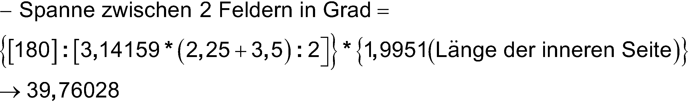
![]()
![]()
Für jedes weitere Feld innerhalb desselben Bogens gilt dann wieder:
Diese Berechnung wird nach außen fortgesetzt.This calculation is continued externally.
Hinweis: In diesem Beispiel wurde jeweils der äußere Kreisbogen eines Feldes statt dem mittleren zur Auswahl des zugehörigen Mittelpunktes genutzt.Note: In this example, the outer arc of a field was used instead of the middle one to select the corresponding center point.
Es soll hier auf
Für die Anwendung dieser Netzstruktur auf die im Verfahren nach Anspruch 1 beschriebenen Weise wird eine Vereinfachung vorgeschlagen, sodass ein Computerprogramm für die Ausführung nicht unnötig viel Zeit und Energie beansprucht. Möglich wäre es, allen Feldern innerhalb der Länge eines Bogens die gleiche tangentiale Ausdehnung zuzuweisen, welche sich dann bspw. aus dem mittleren Abstand zweier Kreisbögen ergibt. Auch die Regelung an den Knickstellen lässt sich vereinfachen, indem bspw. jeweils der innere „mittlere Kreisbogen“ als Berechnungsgrundlage gilt.For the application of this network structure in the manner described in the method according to
Sinnvolle Kombinationen/SonderformUseful combinations/special shapes
Es soll an dieser Stelle auf den Patentanspruch Nummer 9 verwiesen werden.At this point, reference should be made to patent claim number 9.
Da geläufige Bildschirme nun mal an ein rasterförmiges System von Bildpunkten gebunden sind, ist es notwendig, ein nach dem Verfahren in Anspruch 1 entstandenes Bild zum Zweck der Anzeige an deren Raster anzupassen. Bezogen auf die wirtschaftliche Anwendung des Verfahrens nach Anspruch 1 ergibt sich folgende weitere Überlegung:
- Es wäre sinnvoll, wenn ein nach dem Verfahren erzeugtes Bild unabhängig davon, wie stark man es heranholt (wie stark man zoomt), in der Anzeige immer etwa gleich gut aufgelöst werden könnte, ohne dass sich dabei der Speicherbedarf des nach dem Verfahren in
Anspruch 1 erzeugten Bildes unnötig erhöht. Wichtig ist hierbei der Parameter, welcher das Wachstum angibt, das heißt wie viele Felder pro Ring hinzu kommen.
- It would make sense if an image created using the method could always be displayed with approximately the same resolution, regardless of how closely you zoom in (how much you zoom), without reducing the memory requirement of the image created using the method in
claim 1 generated image is increased unnecessarily. What is important here is the parameter that indicates the growth, i.e. how many fields are added per ring.
Als mögliche Definition einer „ausreichend hohen Darstellungsauflösung“ könnte gelten, dass ein Pixel in der Anzeige mindestens der Fläche eines ganzen Feldes der jeweiligen Netzstruktur entspricht.A possible definition of a “sufficiently high display resolution” could be that a pixel in the display corresponds to at least the area of an entire field of the respective network structure.
Dies wiederum ist jeweils dann gegeben, wenn die Auflösung in dem Bereich des Bildes, welcher am wenigsten gut aufgelöst wird, wenigstens einem Feld der Netzstruktur pro ausgegebenen/angezeigtem Pixel entspricht.This in turn is the case when the resolution in the area of the image that is least well resolved corresponds to at least one field of the network structure per pixel output/displayed.
Sinnvoll wäre hierbei, den Wert für den Parameter „Auflösung“ so zu wählen, dass er der gewünschten endgültigen Anzeigegröße entspricht. Wenn bspw. ein Bild später einmal im Format 500x500 Pixel angezeigt werden soll, sollte man für dessen Auflösung im Falle der quadratischen Netzstruktur den Wert 500 festlegen, sodass bei größtmöglichem Zoomfaktor das Zentrum jener Netzstruktur 1:1, d.h. verlustfrei, angezeigt wird. Daraus ergibt sich, dass nach dem Prinzip dieser Sonderform bspw. im Falle der quadratischen Netzstruktur ein Wachstumswert von 2 zu verwenden ist (d.h. die Anzahl der Quadrate/Felder einer Reihe bleibt über das gesamte, auf diese Weise entstandene Bild konstant).It would make sense to choose the value for the “Resolution” parameter so that it corresponds to the desired final display size. If, for example, an image is to be displayed later in the format 500x500 pixels, you should set the resolution to 500 in the case of the square network structure, so that with the largest possible zoom factor, the center of that network structure is displayed 1:1, i.e. without loss. This means that according to the principle of this special form, for example in the case of a square network structure, a growth value of 2 should be used (i.e. the number of squares/fields in a row remains constant over the entire image created in this way).
AusführungsartenTypes of execution
Verfahren zum Konvertieren von RasterbilddateienMethod for converting raster image files
Durch das Verfahren nach Anspruch 1 besteht bspw. die Möglichkeit, ein geläufiges digitales Rasterbild, bspw. ein Bild im png-Format (Es ist ebenfalls denkbar, Vektorgrafiken auf diese Art und Weise zu konvertieren) in eine spezielle Art von Vektorgrafik zu konvertieren, beispielsweise eine Scalable Vector Graphics (.svg) Grafik.The method according to
Neuartiges Dateiformat für BilddateienNew file format for image files
Es soll an dieser Stelle auf den Patentanspruch Nummer 2 verwiesen werden.At this point, reference should be made to
Beschreibung/ÜberlegungenDescription/Considerations
Eine gewöhnliche Rastergrafik wird nicht als Vektordatei gespeichert, obwohl sie ebenfalls in der Theorie aus quadratischen Vektoren und deren Farbwerten besteht. Das kommt daher, dass es effizienter ist, lediglich das Pixelsystem (Spalten und Zeilen bilden bestimmte Anzahl identischer Quadrate) zu kennzeichnen und nach bestimmten Aufzählungsalgorithmen (z.B. von oben nach unten, links nach rechts) die jeweiligen Farbwerte festzulegen. Dadurch wird viel Speicherplatz gespart. So ist auch für das nach Anspruch 1 beschriebene Verfahren ein eigenes Dateiformat denkbar. Dasselbe Programm, welches Bilddateien nach Art des Verfahrens konvertiert, könnte die für die Rekonstruktion eines Bildes nötigen Informationen zwischenspeichern und eine programminterne Dateiform dafür wählen. Dies würde je nach Größe und ausgewählter Netzstruktur eine große bis sehr große Menge an Speicherplatz einsparen. ich möchte hier nur auf die simpelste Form dieses Dateiformates eingehen, die, bei welcher der Ausdehnungswert groß genug ist, um mit der jeweiligen Netzstruktur das gesamte Ursprungsbild zu abzudecken.A normal raster graphic is not saved as a vector file, although in theory it also consists of square vectors and their color values. This is because it is more efficient to simply mark the pixel system (columns and rows form a certain number of identical squares) and to determine the respective color values according to certain enumeration algorithms (e.g. from top to bottom, left to right). This saves a lot of storage space. A separate file format is also conceivable for the method described in
Nötige zu speichernde Bildinformationen/-eigenschaftenNecessary image information/properties to be saved
Für die zweifelsfreie Rekonstruktion eines nach dem in Anspruch 1 beschriebenen Verfahren konvertierten Bildes dieser Art sind folgende Informationen nötig:
- - Die Art der Netzstruktur (quadratisch, dreieckig, rund, spiralförmig)
- - Alle nötigen Parameter (Ort, Größe, Auflösung, Färbung, Wachstum, Wachstumsänderung, Drehung, Ausdehnung, Teilung, Teilungswachstum, Verdrehung, Verdrehungswachstum, Bogenlänge)
- - Der Algorithmus, in welchem die Reihenfolge der Festlegung der Farbwerte der einzelnen Felder angegeben wird. Dieser ist jeweils einer Netzstruktur zugehörig.
- - The type of mesh structure (square, triangular, round, spiral)
- - All necessary parameters (location, size, resolution, coloring, growth, growth change, rotation, expansion, division, division growth, twist, twist growth, arc length)
- - The algorithm in which the order in which the color values of the individual fields are determined is specified. This is assigned to a network structure.
Algorithmen für die Reihenfolge der Festlegung der FarbwerteAlgorithms for the order of determining color values
Dies sind Beispiele für mögliche Algorithmen zur Festlegung der Farbwerte jedes einzelnen Feldes einer Netzstruktur, jeweils zugehörig zu einer bestimmten Art der Netzstruktur.These are examples of possible algorithms for determining the color values of each individual field of a network structure, each belonging to a specific type of network structure.
- (a) Die Quadratische Netzstruktur- (a) The square network structure
Die Zeilen des Zentrums werden, beginnend mit der obersten, von links nach rechts ausgelesen/festgelegt; anschließend wird mit dem ersten umgebenden Ring begonnen. Dort wird wieder zunächst der Farbwert für das linke, obere Quadrat festgelegt, bevor man im Uhrzeigersinn um das Zentrum herum fortfährt. Anschließend wird mit dem zweiten Ring/der zweiten Reihe begonnen. Das Bild wird also von innen (vom Zentrum) heraus gespeichert.The rows of the center are read/set from left to right, starting with the top one; Then you start with the first surrounding ring. There you first set the color value for the upper left square before continuing clockwise around the center. Then start with the second ring/row. So the image is saved from the inside (from the center) out.
- (b) Die runde Netzstruktur- (b) The round network structure
Begonnen wird mit dem Feld im Zentrum der nach dem Verfahren nach Anspruch 1 erstellten Netzstruktur, welches sich rechts des senkrecht nach oben gerichteten Radius des Zentrums befindet, anschließend wird im Uhrzeigersinn fortgefahren. Bei Anwendung des Parameters Teilung werden die dementsprechend kleineren Einheiten/Felder berücksichtigt und der Reihe nach erst im Uhrzeigersinn, dann von innen nach außen aufgegriffen. Anschließend wird mit dem zweiten Ring fortgefahren, wobei wieder genau bei 90 Grad begonnen wird - bei Anwendung des Parameters Verdrehung um die entsprechende Gradzahl verschoben. Das Bild wird also von innen (vom Zentrum) heraus gespeichert.It starts with the field in the center of the network structure created according to the method according to
- (c) Die dreieckige Netzstruktur- (c) The triangular network structure
Die Zeilen des Zentrums werden, beginnend mit der obersten, von links nach rechts ausgelesen/festgelegt (Wobei eine Zeile jeweils aus gedrehten und nicht gedrehten Dreiecken besteht, d.h. bei einem Wert von 10 für den Parameter Auflösung ergeben sich genau 10 Zeilen), anschließend wird mit den ersten umgebenden Reihen/dem ersten Ring begonnen. Dort wird zunächst der Farbwert für das sich an der Spitze des Rings befindliche Dreieck festgelegt, bevor man dann im Uhrzeigersinn fortfährt. Anschließend wird mit dem zweiten Ring/der zweiten Reihe begonnen. Das Bild wird also von innen (vom Zentrum) heraus gespeichert.The rows of the center are read/set, starting with the top one, from left to right (whereby each row consists of rotated and non-rotated triangles, i.e. with a value of 10 for the resolution parameter, this results in exactly 10 lines), then started with the first surrounding rows/ring. There you first set the color value for the triangle at the tip of the ring before continuing in a clockwise direction. Then start with the second ring/row. So the image is saved from the inside (from the center) out.
- (d) Die spiralförmige Netzstruktur- (d) The spiral network structure
Das Bild wird von innen (vom Zentrum) heraus gespeichert.The image is saved from the inside (from the center) out.
Weitere ÜberlegungenFurther considerations
Für eine weitere Komprimierung ist es denkbar, die für Rasterbildgrafiken geläufigen Komprimierungsmethoden auf das neuartige Bildformat zu übertragen, bspw. In Form von Lauflängenkodierung. Diese erneute Einsparung von Speicherbedarf ist in dem Sinne bei einer gewöhnlichen Vektorgrafik wie bspw. Scalable Vector Graphics (.svg) nicht möglich.For further compression, it is conceivable to transfer the compression methods commonly used for raster image graphics to the new image format, for example in the form of run-length coding. This further saving in memory requirements is not possible with ordinary vector graphics such as Scalable Vector Graphics (.svg).
Die eigene Dateiform bietet zudem die Möglichkeit, einen Mittelpunkt zu kennzeichnen. Öffnet man eine in diesem Format gespeicherte Datei mit einem kompatiblen Programm, so kann der Zoom auf jenen Mittelpunkt ausgerichtet werden und einrasten - d.h. wenn man ein Bild heranholt/vergrößert, wird automatisch das Zentrum und der Mittelpunkt der zugehörigen Netzstruktur herangeholt, auch wenn er sich nicht in der Mitte des Bildes befindet.The own file format also offers the possibility of marking a center point. If you open a file saved in this format with a compatible program, the zoom can be aligned to that center and snap into place - i.e. when you zoom in/enlarge an image, the center and center of the associated network structure are automatically brought up, even if it is is not in the center of the image.
Dieses Format für Bilddateien zeichnet sich durch eine hohe Individualität aus und könnte aufgrund dessen große Chancen haben, über die Jahre von einigen geläufigen Bildanzeige- oder -bearbeitungsprogrammen akzeptiert zu werden, sodass es nicht mehr notwendig ist, für eine Verwendung jener Bilddateien speziell darauf zugeschnittene Programme zu nutzen. Da durch derartige Bilddateien Vorteile gewonnen werden können, welche der momentane Stand der Technik nicht hergibt, sollten sich auf Dauer kaum bis gar keine Kompatibilitätsprobleme ergeben. Nichtsdestotrotz erscheint ein allgemein anerkanntes und weiträumig bekanntes Vektorformat zur Verbreitung und Bekanntmachung von aus dem Verfahren in Anspruch 1 hervorgegangenen Bildern sehr nützlich.This format for image files is characterized by a high degree of individuality and could therefore have a good chance of being accepted by some common image viewing or editing programs over the years, so that it is no longer necessary to use programs specifically designed for these image files to use. Since such image files can provide advantages that the current state of the art does not provide, there should be little to no compatibility problems in the long run. Nevertheless, a generally accepted and widely known vector format for distributing and publicizing images resulting from the method in
Effekt in der BildbearbeitungEffect in image editing
Ebenso wie auf die reine Konvertierung, ist das Verfahren nach Anspruch 1 auf die reine digitale Bildbearbeitung anwendbar. Als reiner Effekt ist das Verfahren vor Allem dadurch gekennzeichnet, dass die einem digitalen Rasterbild zugrundeliegende Rasterstruktur unangetastet bleibt, bzw. nach Abschluss der Bildbearbeitung wieder in Kraft tritt.As well as pure conversion, the method according to
Erscheinungsformen im VideobereichAppearances in the video sector
Alle hier erwähnten Ausführungsarten sind auf Videos übertragbar. Nach dem Verfahren nach Anspruch 1 können Videos in ein Vektor-Format konvertiert werden, indem es auf jedes der einzelnen Bilder angewandt wird. So ist ebenfalls ein eigener Dateityp für auf diese Weise entstandene Videos denkbar. (Neuartiges Dateiformat nach Anspruch 2, lediglich auf Videos übertragen)All types of execution mentioned here can be transferred to videos. According to the method according to
Bezogen auf die Bearbeitung von Videomaterial erscheinen neue Parameter sinnvoll, da sicher nicht jedes Bild einzeln bearbeitet werden wird/muss. So könnten bspw. Funktionen für die Veränderung einzelner Parameter pro Frame erstellt werden. Ein interessanter, simpler Effekt wäre bspw. das Drehen der gesamten Netzstruktur von einem Frame zum nächsten. Die Videobearbeitung ist um einiges komplexer und es sind viele Parameter denkbar. Sie sollen hier nicht einzeln aufgeführt werden.When it comes to editing video material, new parameters seem to make sense, as not every image will/need to be edited individually. For example, functions could be created for changing individual parameters per frame. An interesting, simple effect would be rotating the entire network structure from one frame to the next. Video editing is much more complex and many parameters are conceivable. They should not be listed individually here.
Der Einsatz von maschinellem LernenThe use of machine learning
Da es sich gegebenenfalls für bestimmte Anwendungszwecke nicht lohnt, manuell einzelne Bilder nach dem Verfahren nach Anspruch 1, bzw. dem Verfahren nach Anspruch 2 zu konvertieren, könnte es sinnvoll sein, das sogenannte „Maschinelle Lernen“ anzuwenden und dadurch ein oder mehrere Bilddateien völlig automatisch zu konvertieren. Dabei handelt es sich um die künstliche Erzeugung von Wissen aus der Erfahrung heraus. Angewandt auf eine Konvertierung nach dem Verfahren aus Anspruch 1 ergeben sich einige sinnvolle Herangehensweisen.Since it may not be worthwhile for certain applications to manually convert individual images using the method according to
Eine Möglichkeit wäre es, der Software, welche das „Maschinelle Lernen“ ausführt, durch überwachtes Lernen, d.h. der Algorithmus lernt eine Funktion aus gegebenen Ein- und Ausgaben, beizubringen, auf welche Inhalte und Informationen aus den ursprünglichen Bildern es ankommt. So könnten Gesichtserkennungsalgorithmen integriert sein, Algorithmen, welche Symbole und Schriftzüge auswerten oder auch Algorithmen, welche Wiederholungen (bspw. über mehrere Bilder/Fotografien hinweg) ausfindig machen.One possibility would be to teach the software that carries out the “machine learning” what content and information from the original images is important through supervised learning, i.e. the algorithm learns a function from given inputs and outputs. Facial recognition algorithms could be integrated, algorithms that evaluate symbols and lettering or algorithms that identify repetitions (e.g. across several images/photographs).
AnwendungsbeispieleApplication examples
Hervorheben von Objekten/Personen/etc. in BildernHighlighting objects/people/etc. in pictures
Man stelle sich bspw. großformatige Landschaftsbilder vor, auf welchen irgendwo im Hintergrund zwei Personen zu sehen sind. Man kann an die Personen heranzoomen, die Auflösung des Bildes ist hoch genug, um diese auch in vergrößerter Form hoch aufgelöst anzuzeigen. Der Rest des Bildes benötigt die hohe Auflösung jedoch oft gar nicht und so lässt sich, nach dem in Anspruch 1 beschriebenen Verfahren, die Größe, der Ort und die Auflösung eines detaillierten Bereiches festlegen, während die Aufmerksamkeit vom Rest des Bildes harmonisch abgewandt wird. Eine Menge Speicherplatz wird gespart (vor Allem beim eigenen Dateiformat), ein Fokus ist gesetzt, ein harmonischer Übergang gewährleistet und nicht zuletzt: Die Art der Felderstruktur kann je nach Einsatzgebiet festgelegt werden (quadratisch, dreieckig, rund, spiralförmig).For example, imagine large-format landscape pictures in which two people can be seen somewhere in the background. You can zoom in on the people; the resolution of the image is high enough to display them in high resolution in an enlarged form. However, the rest of the image often does not require the high resolution at all and so, using the method described in
Verbinden von Standortinformationen mit lokalen DetailsConnecting location information with local details
Wendet man das Verfahren nach Anspruch 1 auf eine detaillierte Luftaufnahme, welche bspw. per Drohne oder Satellit aufgenommen wurde, an, lässt sich ein Ort innerhalb des Bildes detailliert darstellen, wobei die Umgebung nach außen hin harmonisch und stufenweise verschwimmt. So kann zum einen ersichtlich werden, wo genau sich etwas befindet, während man zum anderen genaue Informationen zu jenem Ort/Gegenstand/etc. abrufen kann. Auch hier hat man mit zunehmender Größe eines zu bearbeitenden digitalen Bildes den Vorteil, enorm viel Speicherplatz einsparen zu können. Firmen und Privatpersonen können bspw. zum Kennzeichnen des Standortes eines Firmen- oder Wohngebäudes auf ihrer Website ein Bild nach diesem Verfahren erstellen und verwenden, statt wie häufig von externen Servern Kartendaten einzubetten. In Kombination mit einer Zoom-Einrastfunktion (Zoomt man mittels eines Reglers, wird automatisch das Zentrum/der Mittelpunkt einer nach Anspruch 2 beschriebenen Grafikdatei herangeholt), bildet dies eine sinnvolle Alternative zum Einbinden von Kartendaten.If the method according to
Es wurde zu diesem Thema speziell für die quadratische Netzstruktur ein Rechenbeispiel vorbereitet:
- Wählt man für den detaillierten Bereich, das Zentrum (Beispielsweise ein Gebäude von 100 Metern x 100 Metern Ausmaße, 1ha), eine Auflösung von 500 x 500 Pixel und möchte man, dass das Gesamtbild einen Bereich von 10'000km x 10'000km abdeckt, erhält man nach dem
Verfahren nach Anspruch 1 und einem harmonischem Wert für das Wachstum von 2 (siehe dazu auch Sinnvolle Kombinationen/Sonderform) im Vergleich zu geläufigen Rasterbildgrafiken folgende Werte:- - Anzahl Megapixel bei gleichmäßiger Auflösung (25 Pixel pro m2): ca. 250'000'000
- - Ungefährer Speicherbedarf als 24bit png:
ca. 750 TB (Terabyte) -
bei 3 byte pro Pixel - - Anzahl Megapixel (Anzahl der „Felder“ dividiert durch 1'000'000) nach dem Verfahren nach Anspruch 1: ca. 5,78
- - Ungefährer Speicherbedarf als 24bit svg: ca. 1006 MB (Megabyte) - bei 174 byte pro Pixel
- - Unverbindliche Vermutung über den Speicherbedarf bei Verwendung eines neuartigen Dateiformates nach Anspruch 2 (ebenfalls 24bit):
- - Unverbindliche Vermutung über den Speicherbedarf bei Verwendung eines neuartigen Dateiformates nach Anspruch 2 (8bit - 256 Farben):
- If you choose a resolution of 500 x 500 pixels for the detailed area, the center (for example a building measuring 100 meters x 100 meters, 1ha), and you want the overall image to cover an area of 10,000km x 10,000km, is obtained by the method according to
claim 1 and a harmonic value for growth of 2 (see also Useful combinations/special form) compared to common raster image graphics:- - Number of megapixels with uniform resolution (25 pixels per m 2 ): approx. 250,000,000
- - Approximate storage requirement as a 24bit png: approx. 750 TB (terabytes) - at 3 bytes per pixel
- - Number of megapixels (number of “fields” divided by 1,000,000) according to the method according to claim 1: approx. 5.78
- - Approximate memory requirement as a 24bit svg: approx. 1006 MB (megabytes) - at 174 bytes per pixel
- - Non-binding assumption about the memory requirement when using a new file format according to claim 2 (also 24bit):
- - Non-binding assumption about the memory requirement when using a new file format according to claim 2 (8bit - 256 colors):
Individuelle Anpassung von Felderstrukturen (künstlerischer Wert)Individual adaptation of field structures (artistic value)
Neben dem Vermitteln der wichtigsten Informationen bei (beinahe) kleinstmöglichem Speicherplatzverbrauch und gleichzeitig völlig harmonischen Übergängen, kann das Verfahren zusätzlich als Kunstform verstanden werden. Es ist bspw. möglich, für ein Bild kreisförmig angeordnete Felder nach individuellem Algorithmus zu erstellen, um bspw. ein rundes Objekt passend zu betonen.In addition to conveying the most important information with (almost) the smallest possible storage space consumption and at the same time completely harmonious transitions, the process can also be understood as an art form. For example, it is possible to create circular fields for an image according to an individual algorithm in order to appropriately emphasize a round object, for example.
Unkenntlich machen von Objekten/Personen/etc. in BildernObscuring objects/people/etc. in pictures
Wie in diesem Dokument bereits mehrfach angeschnitten, kann das Verfahren ebenso gut bestimmte Bereiche eines Bildes weniger gut auflösen, während die Auflösung nach außen hin immer weiter zunimmt. Dazu müssen lediglich die richtigen Werte für die verschiedenen Parameter festgelegt werden. Nach dieser Methode kann die Aufmerksamkeit von bestimmten Punkten abgelenkt werden, Personen können unkenntlich gemacht werden. Auch wenn Bilder konvertiert werden, in welchen ohnehin bereits Bereiche existieren, welche weniger gut aufgelöst sind (bspw. ein Autokennzeichen, verschleiert durch reduzieren der Auflösung im betreffenden Bereich), lässt sich dies mithilfe des Verfahrens nach Anspruch 1 harmonisch vertuschen.As already mentioned several times in this document, the process can also resolve certain areas of an image less well, while the resolution continues to increase towards the outside. All you have to do is set the correct values for the various parameters. Using this method, attention can be diverted from certain points and people can be made unrecognizable. Even if images are converted in which areas already exist that are less well-resolved (e.g. a license plate, obscured by reducing the resolution in the relevant area), this can be harmoniously concealed using the method according to
Verschleiern von Entfernungs-/Zoom bedingtem Foto-Stitching im AllgemeinenDisguise distance/zoom related photo stitching in general
Unabhängig von dem in Anspruch 1 beschriebenen Verfahren kann folgendes Vorgehen unter Umständen ganz allgemein betrachtet sinnvoll und leicht umsetzbar sein:
- Es werden mehrere Fotografien eines Motivs erstellt, wobei entweder der Abstand zum Objekt, der (optische) Zoom Faktor der Kamera oder beides verändert wird. Die auf diese Weise entstandenen, sich überlagernden Fotografien, werden anschließend zusammengefügt. Dabei ist auf einen möglichst nahtlosen Übergang zwischen zwei Aufnahmen zu achten. Es gibt bereits viele Methoden, mittels derer sich mehrere digitale Bilder zusammenfügen lassen, es soll hier auf keine besondere Bezug genommen werden. Wichtig ist hierbei auch ein zoom- bzw. entfernungsbedingtes entzerren.
- Several photographs of a subject are created, changing either the distance to the object, the (optical) zoom factor of the camera or both. The overlapping photographs created in this way are then put together. It is important to ensure that the transition between two recordings is as seamless as possible. There are already many methods by which multiple digital images can be stitched together, no specific reference will be made here. It is also important to equalize the zoom or distance.
Daraufhin wird das Verfahren nach Anspruch 1 angewendet. Vorgeschlagen wird hierbei, das Zentrum der jeweiligen Netzstruktur auf den Bildausschnitt mit dem höchsten Zoom-Faktor, bzw. dem aus der niedrigsten Entfernung aufgenommenen Bildausschnitt, zu legen.The method according to
Wirtschaftliche VerwertungEconomic exploitation
-
- Ein Computerprogramm (ebenso sind mobile Applications oder Onlineanwendungen möglich), welches das Verfahren nach Anspruch 1 oder eine Kombination aus mehreren oder allen der in den Patentansprüchen beschriebenen Verfahren, Anwendungsmöglichkeiten und Erzeugnissen umsetzt/anwendet, lässt sich verkaufen oder lizenzieren.- A computer program (mobile applications or online applications are also possible) which implements/applies the method according to
claim 1 or a combination of several or all of the methods, possible applications and products described in the patent claims can be sold or licensed.
Es soll hier auf
- „Mögliche Umsetzung der Benutzeroberfläche eines das
Verfahren nach Anspruch 1 ausführende Computerprogramm“.- - Die Verwendung des Verfahrens nach Anspruch 1 an sich lässt sich lizenzieren, Herausgeber von Bild- und Videobearbeitungsprogrammen, sowie Herausgeber von Kameras mit optischer Zoom-Funktion könnten interessiert sein.
- - Durch das
Verfahren nach Anspruch 1 entstandene digitale Bilder und Videos, sowie zugehörige Druckprodukte aller Art, lassen sich verkaufen. - - Kameras, mit der Option, das
Verfahren nach Anspruch 1 automatisch bzw. manuell anzuwenden, lassen sich verkaufen - - Die Lizenz zur Verwendung von nach dem
Verfahren aus Anspruch 1 entstandenen Bildmaterials kann verkauft werden. Designer, welche durch die Verwendung der in den Ansprüchen 4-6 beschriebenen, der spiralförmigen, oder auch individuellen, Netzstrukturen bestimmte Formen betonen möchten, könnten interessiert sein.
- “Possible implementation of the user interface of a computer program executing the method according to
claim 1”.- - The use of the method according to
claim 1 itself can be licensed; publishers of image and video editing programs, as well as publishers of cameras with an optical zoom function, could be interested. - - Digital images and videos created by the method according to
claim 1, as well as associated printed products of all kinds, can be sold. - - Cameras with the option to use the method according to
claim 1 automatically or manually can be sold - - The license to use image material created using the method of
claim 1 can be sold. Designers who would like to emphasize certain shapes through the use of the spiral or individual network structures described in claims 4-6 may be interested.
- - The use of the method according to
Durch die Erfindung erzielte VorteileAdvantages achieved by the invention
Vorteile der Erfindung wurden in der Beschreibung bereits einige genannt, vor Allem unter „Gelöstes technisches Problem“ findet man Hinweise.Some of the advantages of the invention have already been mentioned in the description, especially under “Solved technical problem” you can find information.
Kurz zusammengefasst lässt sich Folgendes festhalten:
- - Die tendenziell unwichtige Umgebung eines Details kann komprimiert werden, ohne die Auflösung des ausgewählten Details zu beeinträchtigen. Daraus kann sich bei Anwendung des Verfahrens nach Anspruch 1, sowie im Besonderen bei Verwendung des in
Anspruch 2 beschriebenen neuartigen Dateiformats, je nach Größe des ursprünglichen Bildmaterials, ein enorm verringerter Speicherbedarf ergeben. - - Ein fließender, harmonischer Übergang zwischen hoch und weniger hoch aufgelösten Bereichen innerhalb ein und desselben Bildes kann gewährleistet werden.
- - Wichtige Details innerhalb eines Bildes können durch eine höhere Auflösung im Vergleich zum Rest des Bildes betont/hervorgehoben werden.
- - Es sind Bilddateien vorstellbar, welche die Vorteile eines weiten Aufnahmewinkels und einer hohen Auflösung im Zentrum des Bildes vereinen. Die Informationen aus mehreren Bildern, welche entweder aus unterschiedlicher Entfernung oder aber durch die Verwendung unterschiedlicher Zoom-Faktoren
- - The surroundings of a detail, which tend to be unimportant, can be compressed without affecting the resolution of the selected detail. This can result in an enormously reduced storage requirement when using the method according to
claim 1, and in particular when using the novel file format described inclaim 2, depending on the size of the original image material. - - A smooth, harmonious transition between high and lower resolution areas within the same image can be guaranteed.
- - Important details within an image can be emphasized/highlighted using a higher resolution compared to the rest of the image.
- - Image files are conceivable that combine the advantages of a wide recording angle and high resolution in the center of the image. The information from several images, which are either from different distances or by using different zoom factors
FigurenlisteFigure list
Claims (9)
Priority Applications (2)
| Application Number | Priority Date | Filing Date | Title |
|---|---|---|---|
| DE102021005196.3A DE102021005196B4 (en) | 2021-10-13 | 2021-10-13 | Restructuring of digital images by adapting to point-based network structures |
| JP2022162034A JP2023058448A (en) | 2021-10-13 | 2022-10-07 | Reconstruction of digital image material by adaptation in net structure of point base |
Applications Claiming Priority (1)
| Application Number | Priority Date | Filing Date | Title |
|---|---|---|---|
| DE102021005196.3A DE102021005196B4 (en) | 2021-10-13 | 2021-10-13 | Restructuring of digital images by adapting to point-based network structures |
Publications (2)
| Publication Number | Publication Date |
|---|---|
| DE102021005196A1 DE102021005196A1 (en) | 2023-04-13 |
| DE102021005196B4 true DE102021005196B4 (en) | 2023-11-02 |
Family
ID=85705116
Family Applications (1)
| Application Number | Title | Priority Date | Filing Date |
|---|---|---|---|
| DE102021005196.3A Active DE102021005196B4 (en) | 2021-10-13 | 2021-10-13 | Restructuring of digital images by adapting to point-based network structures |
Country Status (2)
| Country | Link |
|---|---|
| JP (1) | JP2023058448A (en) |
| DE (1) | DE102021005196B4 (en) |
Citations (1)
| Publication number | Priority date | Publication date | Assignee | Title |
|---|---|---|---|---|
| DE102020122052B3 (en) | 2020-08-24 | 2021-08-26 | Bareways GmbH | METHOD AND SYSTEM FOR ENCODING IMAGE DATA REPRESENTING A GEOGRAPHIC LINE |
Family Cites Families (5)
| Publication number | Priority date | Publication date | Assignee | Title |
|---|---|---|---|---|
| JP4408836B2 (en) | 2005-05-30 | 2010-02-03 | キヤノン株式会社 | Image processing apparatus, control method therefor, and program |
| WO2011025385A1 (en) | 2009-08-26 | 2011-03-03 | Sinvent As | Method for local refinement of a geometric or physical representation |
| US8766982B2 (en) | 2010-01-19 | 2014-07-01 | Disney Enterprises, Inc. | Vectorization of line drawings using global topology and storing in hybrid form |
| US9451162B2 (en) | 2013-08-21 | 2016-09-20 | Jaunt Inc. | Camera array including camera modules |
| EP3364342A1 (en) | 2017-02-17 | 2018-08-22 | Cogisen SRL | Method for image processing and video compression |
-
2021
- 2021-10-13 DE DE102021005196.3A patent/DE102021005196B4/en active Active
-
2022
- 2022-10-07 JP JP2022162034A patent/JP2023058448A/en active Pending
Patent Citations (1)
| Publication number | Priority date | Publication date | Assignee | Title |
|---|---|---|---|---|
| DE102020122052B3 (en) | 2020-08-24 | 2021-08-26 | Bareways GmbH | METHOD AND SYSTEM FOR ENCODING IMAGE DATA REPRESENTING A GEOGRAPHIC LINE |
Also Published As
| Publication number | Publication date |
|---|---|
| JP2023058448A (en) | 2023-04-25 |
| DE102021005196A1 (en) | 2023-04-13 |
Similar Documents
| Publication | Publication Date | Title |
|---|---|---|
| DE69428491T2 (en) | image lens | |
| DE102006005044B4 (en) | Method and system for determining a data model for superposition with a real object in an object tracking method | |
| DE602004002393T2 (en) | ANTIALIASING METHOD AND DEVICE FOR PRESENTING A REGION OF A TWO-DIMENSIONAL DISTANCE FIELD THAT CONSTITUTES AN OBJECT | |
| DE69534331T2 (en) | Method and device for highlighting the detail of a tree structure | |
| DE102009023756B4 (en) | Proof of origin and authorship of images | |
| DE3446898A1 (en) | METHOD AND DEVICE FOR PRODUCING AN IMAGE EXTRACTION MASK IN THE EVENT OF AN ELECTRONIC IMAGE REPRODUCTION | |
| EP2140403A2 (en) | Device and method for determining an edge histogram, device and method for storing an image in an image database, device and method for finding two similar images and computer program | |
| DE102021128523A1 (en) | HIERARCHICAL IMAGE DECOMPOSITION FOR DEFECT DETECTION | |
| DE69731706T2 (en) | Search method for patterns in images of a database | |
| EP2602591B1 (en) | Method for simplified storage of data representing shapes | |
| DE102021005196B4 (en) | Restructuring of digital images by adapting to point-based network structures | |
| DE3889903T2 (en) | METHOD FOR TREATING THE HIDDEN LINES OF AN IMAGE. | |
| DE19645983C2 (en) | Device and method for image processing | |
| DE102017110339A1 (en) | Computer-implemented method for measuring an object from a digital representation of the object | |
| EP2344845B1 (en) | Method and navigation apparatus for the three-dimensional perspective representation of terrain topography on a two-dimensional display device | |
| EP2893510A1 (en) | Method and image processing system for removing a visual object from an image | |
| DE102011103510A1 (en) | Method for creating three-dimensional CAD representation of e.g. workshop, involves detecting coherent surface elements in scatter-plot representation, and creating three-dimensional CAD representation of object arrangement | |
| DE60305027T2 (en) | Method for providing a vector image with hidden lines hidden | |
| EP0870275B1 (en) | Method of pattern recognition and method of creating an n-dimensional object | |
| DE69322216T2 (en) | Method and device for graphic pattern generation | |
| DE69429402T2 (en) | Process and system for the production of table images with focus and context zones, which represent direct and indirect data representations | |
| DE4209936C2 (en) | Terrain image simulator | |
| DE102019132529A1 (en) | Method for extracting, reading out and / or outputting information hidden in a printed and / or visually designed surface | |
| EP3718075B1 (en) | Method for producing a personal portrait for an identity document | |
| DE102013207066A1 (en) | Method for storing altitude profile data, as well as profile data and method for generating a height profile from these profile data |
Legal Events
| Date | Code | Title | Description |
|---|---|---|---|
| R086 | Non-binding declaration of licensing interest | ||
| R012 | Request for examination validly filed | ||
| R016 | Response to examination communication | ||
| R016 | Response to examination communication | ||
| R018 | Grant decision by examination section/examining division | ||
| R020 | Patent grant now final |