DE102020130523B4 - METHOD OF FORMING A PHOTORESIST STRUCTURE - Google Patents
METHOD OF FORMING A PHOTORESIST STRUCTURE Download PDFInfo
- Publication number
- DE102020130523B4 DE102020130523B4 DE102020130523.0A DE102020130523A DE102020130523B4 DE 102020130523 B4 DE102020130523 B4 DE 102020130523B4 DE 102020130523 A DE102020130523 A DE 102020130523A DE 102020130523 B4 DE102020130523 B4 DE 102020130523B4
- Authority
- DE
- Germany
- Prior art keywords
- photoresist
- protective layer
- photoresist layer
- layer
- acid
- Prior art date
- Legal status (The legal status is an assumption and is not a legal conclusion. Google has not performed a legal analysis and makes no representation as to the accuracy of the status listed.)
- Active
Links
Images


Classifications
-
- G—PHYSICS
- G03—PHOTOGRAPHY; CINEMATOGRAPHY; ANALOGOUS TECHNIQUES USING WAVES OTHER THAN OPTICAL WAVES; ELECTROGRAPHY; HOLOGRAPHY
- G03F—PHOTOMECHANICAL PRODUCTION OF TEXTURED OR PATTERNED SURFACES, e.g. FOR PRINTING, FOR PROCESSING OF SEMICONDUCTOR DEVICES; MATERIALS THEREFOR; ORIGINALS THEREFOR; APPARATUS SPECIALLY ADAPTED THEREFOR
- G03F7/00—Photomechanical, e.g. photolithographic, production of textured or patterned surfaces, e.g. printing surfaces; Materials therefor, e.g. comprising photoresists; Apparatus specially adapted therefor
- G03F7/004—Photosensitive materials
- G03F7/09—Photosensitive materials characterised by structural details, e.g. supports, auxiliary layers
- G03F7/11—Photosensitive materials characterised by structural details, e.g. supports, auxiliary layers having cover layers or intermediate layers, e.g. subbing layers
-
- G—PHYSICS
- G03—PHOTOGRAPHY; CINEMATOGRAPHY; ANALOGOUS TECHNIQUES USING WAVES OTHER THAN OPTICAL WAVES; ELECTROGRAPHY; HOLOGRAPHY
- G03F—PHOTOMECHANICAL PRODUCTION OF TEXTURED OR PATTERNED SURFACES, e.g. FOR PRINTING, FOR PROCESSING OF SEMICONDUCTOR DEVICES; MATERIALS THEREFOR; ORIGINALS THEREFOR; APPARATUS SPECIALLY ADAPTED THEREFOR
- G03F7/00—Photomechanical, e.g. photolithographic, production of textured or patterned surfaces, e.g. printing surfaces; Materials therefor, e.g. comprising photoresists; Apparatus specially adapted therefor
- G03F7/004—Photosensitive materials
- G03F7/0045—Photosensitive materials with organic non-macromolecular light-sensitive compounds not otherwise provided for, e.g. dissolution inhibitors
-
- G—PHYSICS
- G03—PHOTOGRAPHY; CINEMATOGRAPHY; ANALOGOUS TECHNIQUES USING WAVES OTHER THAN OPTICAL WAVES; ELECTROGRAPHY; HOLOGRAPHY
- G03F—PHOTOMECHANICAL PRODUCTION OF TEXTURED OR PATTERNED SURFACES, e.g. FOR PRINTING, FOR PROCESSING OF SEMICONDUCTOR DEVICES; MATERIALS THEREFOR; ORIGINALS THEREFOR; APPARATUS SPECIALLY ADAPTED THEREFOR
- G03F7/00—Photomechanical, e.g. photolithographic, production of textured or patterned surfaces, e.g. printing surfaces; Materials therefor, e.g. comprising photoresists; Apparatus specially adapted therefor
- G03F7/004—Photosensitive materials
- G03F7/0046—Photosensitive materials with perfluoro compounds, e.g. for dry lithography
-
- G—PHYSICS
- G03—PHOTOGRAPHY; CINEMATOGRAPHY; ANALOGOUS TECHNIQUES USING WAVES OTHER THAN OPTICAL WAVES; ELECTROGRAPHY; HOLOGRAPHY
- G03F—PHOTOMECHANICAL PRODUCTION OF TEXTURED OR PATTERNED SURFACES, e.g. FOR PRINTING, FOR PROCESSING OF SEMICONDUCTOR DEVICES; MATERIALS THEREFOR; ORIGINALS THEREFOR; APPARATUS SPECIALLY ADAPTED THEREFOR
- G03F7/00—Photomechanical, e.g. photolithographic, production of textured or patterned surfaces, e.g. printing surfaces; Materials therefor, e.g. comprising photoresists; Apparatus specially adapted therefor
- G03F7/004—Photosensitive materials
- G03F7/039—Macromolecular compounds which are photodegradable, e.g. positive electron resists
- G03F7/0392—Macromolecular compounds which are photodegradable, e.g. positive electron resists the macromolecular compound being present in a chemically amplified positive photoresist composition
- G03F7/0397—Macromolecular compounds which are photodegradable, e.g. positive electron resists the macromolecular compound being present in a chemically amplified positive photoresist composition the macromolecular compound having an alicyclic moiety in a side chain
-
- G—PHYSICS
- G03—PHOTOGRAPHY; CINEMATOGRAPHY; ANALOGOUS TECHNIQUES USING WAVES OTHER THAN OPTICAL WAVES; ELECTROGRAPHY; HOLOGRAPHY
- G03F—PHOTOMECHANICAL PRODUCTION OF TEXTURED OR PATTERNED SURFACES, e.g. FOR PRINTING, FOR PROCESSING OF SEMICONDUCTOR DEVICES; MATERIALS THEREFOR; ORIGINALS THEREFOR; APPARATUS SPECIALLY ADAPTED THEREFOR
- G03F7/00—Photomechanical, e.g. photolithographic, production of textured or patterned surfaces, e.g. printing surfaces; Materials therefor, e.g. comprising photoresists; Apparatus specially adapted therefor
- G03F7/004—Photosensitive materials
- G03F7/09—Photosensitive materials characterised by structural details, e.g. supports, auxiliary layers
- G03F7/095—Photosensitive materials characterised by structural details, e.g. supports, auxiliary layers having more than one photosensitive layer
-
- G—PHYSICS
- G03—PHOTOGRAPHY; CINEMATOGRAPHY; ANALOGOUS TECHNIQUES USING WAVES OTHER THAN OPTICAL WAVES; ELECTROGRAPHY; HOLOGRAPHY
- G03F—PHOTOMECHANICAL PRODUCTION OF TEXTURED OR PATTERNED SURFACES, e.g. FOR PRINTING, FOR PROCESSING OF SEMICONDUCTOR DEVICES; MATERIALS THEREFOR; ORIGINALS THEREFOR; APPARATUS SPECIALLY ADAPTED THEREFOR
- G03F7/00—Photomechanical, e.g. photolithographic, production of textured or patterned surfaces, e.g. printing surfaces; Materials therefor, e.g. comprising photoresists; Apparatus specially adapted therefor
- G03F7/26—Processing photosensitive materials; Apparatus therefor
- G03F7/30—Imagewise removal using liquid means
- G03F7/32—Liquid compositions therefor, e.g. developers
- G03F7/322—Aqueous alkaline compositions
-
- G—PHYSICS
- G03—PHOTOGRAPHY; CINEMATOGRAPHY; ANALOGOUS TECHNIQUES USING WAVES OTHER THAN OPTICAL WAVES; ELECTROGRAPHY; HOLOGRAPHY
- G03F—PHOTOMECHANICAL PRODUCTION OF TEXTURED OR PATTERNED SURFACES, e.g. FOR PRINTING, FOR PROCESSING OF SEMICONDUCTOR DEVICES; MATERIALS THEREFOR; ORIGINALS THEREFOR; APPARATUS SPECIALLY ADAPTED THEREFOR
- G03F7/00—Photomechanical, e.g. photolithographic, production of textured or patterned surfaces, e.g. printing surfaces; Materials therefor, e.g. comprising photoresists; Apparatus specially adapted therefor
- G03F7/26—Processing photosensitive materials; Apparatus therefor
- G03F7/30—Imagewise removal using liquid means
- G03F7/32—Liquid compositions therefor, e.g. developers
- G03F7/325—Non-aqueous compositions
-
- G—PHYSICS
- G03—PHOTOGRAPHY; CINEMATOGRAPHY; ANALOGOUS TECHNIQUES USING WAVES OTHER THAN OPTICAL WAVES; ELECTROGRAPHY; HOLOGRAPHY
- G03F—PHOTOMECHANICAL PRODUCTION OF TEXTURED OR PATTERNED SURFACES, e.g. FOR PRINTING, FOR PROCESSING OF SEMICONDUCTOR DEVICES; MATERIALS THEREFOR; ORIGINALS THEREFOR; APPARATUS SPECIALLY ADAPTED THEREFOR
- G03F7/00—Photomechanical, e.g. photolithographic, production of textured or patterned surfaces, e.g. printing surfaces; Materials therefor, e.g. comprising photoresists; Apparatus specially adapted therefor
- G03F7/26—Processing photosensitive materials; Apparatus therefor
- G03F7/38—Treatment before imagewise removal, e.g. prebaking
Landscapes
- Physics & Mathematics (AREA)
- General Physics & Mathematics (AREA)
- Spectroscopy & Molecular Physics (AREA)
- Engineering & Computer Science (AREA)
- Architecture (AREA)
- Structural Engineering (AREA)
- Materials For Photolithography (AREA)
- Photosensitive Polymer And Photoresist Processing (AREA)
- Mechanical Treatment Of Semiconductor (AREA)
- Die Bonding (AREA)
- Exposure And Positioning Against Photoresist Photosensitive Materials (AREA)
Abstract
Verfahren zur Bildung einer Fotolackstruktur, umfassend:Bilden einer Schutzschicht über einer Fotolackschicht, die auf einem Substrat gebildet wird;selektives Belichten der Schutzschicht und der Fotolackschicht mit aktinischer Strahlung; undEntwickeln der Fotolackschicht, um eine Struktur in der Fotolackschicht zu bilden,wobei die Schutzschicht ein Polymer ohne stickstoffhaltigen Rest und eine oder mehrere Komponenten umfasst, die ausgewählt sind aus einem basischen Quencher, einer organischen Säure, einem Fotosäuregenerator oder einem thermischen Säuregenerator.A method of forming a photoresist pattern, comprising:forming a protective layer over a photoresist layer formed on a substrate;selectively exposing the protective layer and the photoresist layer to actinic radiation; anddeveloping the photoresist layer to form a pattern in the photoresist layer,wherein the protective layer comprises a polymer free of a nitrogen-containing moiety and one or more components selected from a basic quencher, an organic acid, a photoacid generator, or a thermal acid generator.
Description
HINTERGRUNDBACKGROUND
Da Verbrauchervorrichtungen aufgrund der Nachfrage der Verbraucher immer kleiner geworden sind, wurden notwendigerweise auch die Einzelkomponenten dieser Vorrichtungen verkleinert. Halbleiterbauelemente, die einen Hauptteil solcher Vorrichtungen wie Mobiltelefone, Computer-Tablets und dergleichen darstellen, mussten immer kleiner werden, wodurch auch die Größe der einzelnen Bauelemente (z. B. Transistoren, Widerstände, Kondensatoren usw.) unter den Halbleiterbauelementen reduziert werden musste.As consumer devices have become smaller and smaller in response to consumer demand, the individual components of these devices have necessarily been miniaturized as well. Semiconductor devices, which are a main part of such devices as mobile phones, computer tablets, and the like, have been required to be miniaturized, which has also required reduction in the size of individual devices (e.g., transistors, resistors, capacitors, etc.) among the semiconductor devices.
Eine Grundlagentechnologie, die in den Fertigungsprozessen von Halbleiterbauelementen verwendet wird, ist der Einsatz von lichtempfindlichen Materialien. Solche Materialien werden auf eine Oberfläche aufgebracht und mit einer Energie belichtet, die selbst strukturiert wurde. Solch eine Belichtung modifiziert die chemischen und physikalischen Eigenschaften der belichteten Regionen des lichtempfindlichen Materials. Diese Modifikation kann zusammen mit dem Fehlen von Modifikation in Regionen des lichtempfindlichen Materials, die nicht belichtet wurden, zum Entfernen einer Region ohne Entfernen der anderen genutzt werden.A basic technology used in the manufacturing processes of semiconductor components is the use of light-sensitive materials. Such materials are applied to a surface and exposed to an energy that has itself been patterned. Such exposure modifies the chemical and physical properties of the exposed regions of the photosensitive material. This modification, together with the lack of modification in regions of the photosensitive material that were not exposed, can be used to remove one region without removing the other.
Mit kleiner werdendem Strukturabstand kann jedoch Belichtungsstrahlung aufgrund von Lichtstreuung in die Regionen des Fotolacks eindringen, die unbelichtet bleiben sollen. Die eingedrungene Belichtungsstrahlung kann zu einer Verschlechterung des Fotolacks in den unbelichteten Bereichen führen und Strukturfehler verursachen. Da die Größe einzelner Bauelemente abgenommen hat, werden Prozessfenster zur fotolithografischen Verarbeitung immer kleiner. Dementsprechend sind Fortschritte auf dem Gebiet der fotolithografischen Verarbeitung notwendig, um die Fähigkeit zum Verkleinern der Bauelemente aufrechtzuerhalten, und es werden weitere Verbesserungen benötigt, um die gewünschten Designkriterien zu erfüllen, derart dass die Entwicklung zu immer kleineren Komponenten fortgesetzt werden kann.
Figurenlistecharacter list
Die vorliegende Offenbarung lässt sich am besten anhand der folgenden ausführlichen Beschreibung in Verbindung mit den beiliegenden Figuren verstehen. Es ist zu beachten, dass gemäß der branchenüblichen Praxis verschiedene Merkmale nicht maßstabgerecht dargestellt sind und lediglich Veranschaulichungszwecken dienen. Tatsächlich können die Abmessungen der verschiedenen Merkmale zugunsten einer klaren Erläuterung willkürlich vergrößert oder verkleinert sein.
-
1 veranschaulicht einen Prozessfluss gemäß Ausführungsformen der Offenbarung. -
2A ,2B ,2C und2D stellen Prozessstufen von Folgeabläufen gemäß einer Ausführungsform der Offenbarung dar. -
3A und3B stellen Prozessstufen eines Folgeablaufs gemäß einer Ausführungsform der Offenbarung dar. -
4 stellt eine Prozessstufe eines Folgeablaufs gemäß Ausführungsformen der Offenbarung dar. -
5A und5B stellen Prozessstufen eines Folgeablaufs gemäß einer Ausführungsform der Offenbarung dar. -
6A und6B stellen Prozessstufen eines Folgeablaufs gemäß Ausführungsformen der Offenbarung dar. -
7A und7B stellen Prozessstufen eines Folgeablaufs gemäß einer Ausführungsform der Offenbarung dar. -
8A und8B stellen Prozessstufen eines Folgeablaufs gemäß einer Ausführungsform der Offenbarung dar. -
9A und9B stellen Prozessstufen eines Folgeablaufs gemäß einer Ausführungsform der Offenbarung dar. -
10 stellt eine Prozessstufe eines Folgeablaufs gemäß einer Ausführungsform der Offenbarung dar. -
11A und11B stellen Prozessstufen eines Folgeablaufs gemäß einer Ausführungsform der Offenbarung dar. -
12 stellt eine Prozessstufe eines Folgeablaufs gemäß einer Ausführungsform der Offenbarung dar. -
13A und13B stellen Prozessstufen eines Folgeablaufs gemäß einer Ausführungsform der Offenbarung dar. -
14A und14B stellen Prozessstufen eines Folgeablaufs gemäß einer Ausführungsform der Offenbarung dar.
-
1 12 illustrates a process flow according to embodiments of the disclosure. -
2A ,2 B ,2C and2D -
3A and3B -
4 12 illustrates a process stage of a subsequent flow according to embodiments of the disclosure. -
5A and5B -
6A and6B illustrate process stages of a sequential flow according to embodiments of the disclosure. -
7A and7B -
8A and8B -
9A and9B -
10 12 illustrates a process stage of a sequential flow according to an embodiment of the disclosure. -
11A and11B -
12 12 illustrates a process stage of a sequential flow according to an embodiment of the disclosure. -
13A and13B -
14A and14B
AUSFÜHRLICHE BESCHREIBUNGDETAILED DESCRIPTION
Es versteht sich, dass die folgende Offenbarung viele verschiedene Ausführungsformen oder Beispiele zum Implementieren verschiedener Merkmale der Offenbarung bereitstellt. Im Folgenden werden spezifische Ausführungsformen oder Beispiele von Komponenten und Anordnungen zum Vereinfachen der vorliegenden Offenbarung beschrieben. Diese sind natürlich nur Beispiele und nicht als Einschränkung gedacht. Zum Beispiel sind Abmessungen von Elementen nicht auf die offenbarten Bereiche oder Werte beschränkt, sondern können von Prozessbedingungen/oder gewünschten Eigenschaften der Vorrichtung abhängen. Außerdem kann die Bildung eines ersten Merkmals über oder auf einem zweiten Merkmal in der folgenden Beschreibung Ausführungsformen, in welchen das erste und das zweite Merkmal in direktem Kontakt ausgebildet sind, sowie Ausführungsformen umfassen, in welche zusätzliche Merkmale ausgebildet sind, die zwischen das erste und das zweite Merkmal eingefügt sind, derart dass das erste und das zweite Merkmal nicht in direktem Kontakt sein können. Verschiedene Merkmale können der Einfach- und Klarheit halber willkürlich in verschiedenen Maßstäben dargestellt sein.It should be understood that the following disclosure provides many different embodiments or examples for implementing various features of the disclosure. In the following, specific embodiments or examples of components and arrangements are described to simplify the present disclosure. Of course, these are only examples and are not intended as limitations. For example, element dimensions are not limited to the disclosed ranges or values, but may depend on process conditions/or desired device properties. Additionally, in the following description, the formation of a first feature over or on top of a second feature may include embodiments in which the first and second features are formed in face-to-face contact, as well as embodiments in which additional features are formed intermediate between the first and the second features are inserted such that the first and second features cannot be in direct contact. Various features may be arbitrarily represented at different scales for simplicity and clarity.
Ferner können raumbezogene Begriffe wie „unterhalb“, „unter“, „untere/s/r“, „über“, „obere/s/r“ und dergleichen hierin zur Vereinfachung der Beschreibung verwendet werden, um eine Beziehung eines Elements oder Merkmals zu einem oder mehreren anderen Element(en) oder Merkmal(en) zu beschreiben, wie in den Figuren veranschaulicht. Die raumbezogenen Begriffe sollen verschiedene Ausrichtungen der Vorrichtung in Verwendung oder Betrieb zusätzlich zu der in den Figuren dargestellten Ausrichtung umfassen. Die Vorrichtung kann anders ausgerichtet (um 90 Grad gedreht oder in anderen Ausrichtungen) sein, und die hierin verwendeten raumbezogenen Bezeichner können ebenfalls demgemäß interpretiert werden. Zudem kann der Begriff „hergestellt aus“ entweder „umfassend“ oder „bestehend aus“ bedeuten.Further, spatial terms such as "underneath," "below," "lower," "above," "upper," and the like may be used herein for ease of description to indicate a relationship of an element or feature to describe one or more other element(s) or feature(s) as illustrated in the figures. The spatial terms are intended to encompass different orientations of the device in use or operation in addition to the orientation depicted in the figures. The device may be otherwise oriented (rotated 90 degrees or at other orientations) and the spatial designators used herein may also be interpreted accordingly. In addition, the term "made of" can mean either "comprising" or "consisting of".
Die belichtete Schutzschicht und Fotolackschicht werden in einigen Ausführungsformen in Arbeitsgang S260 dann nach der Belichtung nachgehärtet. Ein Entwickler 57 wird im Entwicklungsvorgang S270 auf die Schutzschicht 20 und die Fotolackschicht 15 aufgebracht, um die strukturierte Fotolackschicht 55a, 55b zu bilden, wie in
In einigen Ausführungsformen wird jede der Fotolackschicht 15 und der Schutzschicht 20 unter Verwendung eines Prozesses wie beispielsweise eines Aufschleuderprozesses, eines Tauchbeschichtungsverfahrens, eines Luftrakelbeschichtungsverfahrens, eines Vorhangbeschichtungsverfahrens, eines Drahtbarrenbeschichtungsverfahrens, eines Gravurstreichverfahrens, eines Laminierverfahrens, eines Extrusionsbeschichtungsverfahrens, Kombinationen davon oder dergleichen aufgebracht. Wie in
Wie in
In einigen Ausführungsformen wird die selektive Belichtung der Fotolackschicht 15 zum Bilden der belichteten Regionen 50 und der unbelichteten Regionen 52 unter Verwendung von EUV-Lithografie durchgeführt. In einem EUV-lithografischen Vorgang wird eine reflektierende Fotomaske 65 zum Bilden des strukturierten Belichtungslichts verwendet, wie in
Die mit der Strahlung belichtete Region 50 der Fotolackschicht geht eine chemische Reaktion ein, wodurch sich ihre Löslichkeit in einem anschließend aufgebrachten Entwickler in Bezug auf die nicht mit der Strahlung belichtete Region 52 der Fotolackschicht ändert. In einigen Ausführungsformen geht der mit der Strahlung belichtete Teil 50 der Fotolackschicht eine Vernetzungsreaktion ein. In anderen Ausführungsformen umfasst der Fotolack ein Polymer mit seitenständigen Gruppen, die bei Belichtung mit der Strahlung 45 eine Zersetzungsreaktion eingehen.The
Als Nächstes wird die Fotolackschicht 15 in Arbeitsgang S260 einem Nachhärten nach der Belichtung unterzogen. In einigen Ausführungsformen wird die Fotolackschicht 15 für etwa 20 Sekunden bis etwa 120 Sekunden auf eine Temperatur von etwa 50 °C und 160 °C erwärmt. Das Nachhärten nach der Belichtung kann zur Unterstützung beim Erzeugen, Verteilen und Umsetzen der aus dem Auftreffen der Strahlung 45/97 auf die Fotolackschicht 15 während der Belichtung erzeugten Säuren/Basen/Radikale verwendet werden (Arbeitsgang S250). Solch eine Unterstützung hilft, chemische Reaktionen auszulösen oder zu verbessern, die chemische Unterschiede zwischen der belichteten Region 50 und der unbelichteten Region 52 innerhalb der Fotolackschicht erzeugen. Diese chemischen Unterschiede können auch Unterschiede in der Löslichkeit zwischen der belichteten Region 50 und der unbelichteten Region 52 bewirken.Next, the
Die selektiv belichtete Fotolackschicht wird anschließend in Arbeitsgang S270 durch Aufbringen eines Entwicklers auf die selektiv belichtete Fotolackschicht entwickelt. Wie in
In einigen Ausführungsformen wird die Struktur der Öffnungen 55a, 55b in der Fotolackschicht 15 in die zu strukturierende Schicht oder das Substrat 10 verlängert, um eine Struktur von Öffnungen 55a', 55b' im Substrat 10 zu bilden, wodurch die Struktur der Fotolackschicht 15 in das Substrat 10 übertragen wird, wie in
In einigen Ausführungsformen umfasst das Substrat 10 wenigstens auf seinem Oberflächenabschnitt eine einkristalline Halbleiterschicht. Das Substrat 10 kann ein einkristallines Halbleitermaterial, wie beispielsweise Si, Ge, SiGe, GaAs, InSb, GaP, GaSb, InAlAs, InGaAs, GaSbP, GaAsSb und InP, umfassen, ohne darauf beschränkt zu sein. In einigen Ausführungsformen ist das Substrat 10 eine Siliciumschicht eines Silicium-Isolator-Substrats (SOI - Silicon-On Insulator). In bestimmten Ausführungsformen ist das Substrat 10 aus kristallinem Si hergestellt.In some embodiments, the
Das Substrat 10 kann in seiner Oberflächenregion eine oder mehrere Pufferschichten (nicht dargestellt) umfassen. Die Pufferschichten können zum schrittweisen Ändern der Gitterkonstanten von der des Substrats zu der von anschließend gebildeten Source-/Drain-Regionen dienen. Die Pufferschichten können aus epitaxial aufgewachsenen einkristallinen Halbleitermaterialien, wie beispielsweise Si, Ge, GeSn, SiGe, GaAs, InSb, GaP, GaSb, InAlAs, InGaAs, GaSbP, GaAsSb, GaN, GaP, und InP, gebildet sein, ohne darauf beschränkt zu sein. In einer Ausführungsform wird die Pufferschicht aus Siliciumgermanium (SiGe) epitaxial auf das Siliciumsubstrat 10 aufgewachsen. Die Germaniumkonzentration der SiGe-Pufferschicht kann von 30 Atom% für die unterste Pufferschicht bis 70 Atom% für die oberste Pufferschicht zunehmen.The
In einigen Ausführungsformen umfasst das Substrat 10 eine oder mehrere Schichten mindestens eines Metalls, einer Metalllegierung und Metall/Nitrid/Sulfid/Oxid/Silicid mit der Formel MXa, wobei M ein Metall ist, und X N, S, Se, O, Si ist, und a von etwa 0,4 bis etwa 2,5 ist. In einigen Ausführungsformen umfasst das Substrat 10 Titan, Aluminium, Cobalt, Ruthenium, Titannitrid, Wolframnitrid, Tantalnitrid und Kombinationen davon.In some embodiments, the
In einigen Ausführungsformen umfasst das Substrat 10 ein Dielektrikum mit mindestens einem Silicium- oder Metalloxid oder -nitrid der Formel MXb, wobei M ein Metall oder Si ist, X N oder O ist, und b im Bereich von etwa 0,4 bis etwa 2,5 liegt. In einigen Ausführungsformen umfasst das Substrat 10 Siliciumdioxid, Siliciumnitrid, Aluminiumoxid, Hafniumoxid, Lanthanoxid und Kombinationen davon.In some embodiments, the
Die Fotolackschicht 15 ist eine lichtempfindliche Schicht, die durch Belichtung mit aktinischer Strahlung strukturiert wird. Typischerweise ändern sich die chemischen Eigenschaften der Fotolackregionen, die von einfallender Strahlung getroffen werden, auf eine Weise, die vom verwendeten Typ von Fotolack abhängt. Die Fotolackschichten 15 sind entweder Positivtonlacke oder Negativtonlacke. Ein Positivtonlack bezieht sich auf ein Fotolackmaterial, das bei Belichtung mit Strahlung, beispielsweise UV-Licht, in einem Entwickler löslich wird, während die Region des Fotolacks, die nicht (oder weniger) belichtet wird, im Entwickler unlöslich ist (siehe
Ob ein Fotolack ein Positivton- oder Negativtonlack ist, hängt vom Typ von Entwickler ab, der zum Entwickeln des Fotolacks verwendet wird. Zum Beispiel stellen einige Positivton-Fotolacke eine positive Struktur bereit (d. h. die belichteten Regionen werden durch den Entwickler entfernt), wenn der Entwickler ein Entwickler auf wässriger Basis, beispielsweise eine Lösung von Tetramethylammoniumhydroxid (TMAH), ist. Andererseits stellt der gleiche Fotolack eine negative Struktur bereit (d. h. die unbelichteten Regionen werden durch den Entwickler entfernt), wenn der Entwickler ein organisches Lösungsmittel ist. Ferner werden bei einigen Negativton-Fotolacken, die mit der TMAH-Lösung entwickelt werden, die unbelichteten Regionen des Fotolacks durch das TMAH entfernt, und die belichteten Regionen des Fotolacks, die bei Belichtung mit aktinischer Strahlung Vernetzung unterzogen werden, bleiben nach der Entwicklung auf dem Substrat.Whether a photoresist is a positive tone or negative tone resist depends on the type of developer used to develop the photoresist. For example, some positive-tone photoresists provide positive patterning (i.e., the exposed regions are removed by the developer) when the developer is an aqueous-based developer, such as a solution of tetramethylammonium hydroxide (TMAH). On the other hand, when the developer is an organic solvent, the same photoresist provides a negative pattern (i.e., the unexposed regions are removed by the developer). Furthermore, in some negative tone photoresists that are developed with the TMAH solution, the unexposed regions of the photoresist are removed by the TMAH, and the exposed regions of the photoresist that undergo crosslinking upon exposure to actinic radiation remain on the after development substrate.
In einigen Ausführungsformen ist die Dicke der Schutzschicht dünn genug, damit die Schutzschicht die Belichtung der Fotolackschicht 15 mit der Strahlung 45 nicht beeinträchtigt. In einigen Ausführungsformen weist die Schutzschicht eine Dicke im Bereich von etwa 0,1 nm bis etwa 20 nm auf. In einigen Ausführungsformen liegt die Dicke der Schutzschicht im Bereich von etwa 1 nm bis etwa 15 nm. In einigen Ausführungsformen ist der Kontaktwinkel der Schutzschicht zu Wasser größer als 75°.In some embodiments, the thickness of the protective layer is thin enough so that the protective layer does not interfere with the exposure of the
Fotolackzusammensetzungen gemäß der vorliegenden Offenbarung umfassen in einigen Ausführungsformen ein Polymer zusammen mit einer oder mehreren fotoaktiven Verbindungen (PAC - Photoactive Compound) in einem Lösungsmittel. In einigen Ausführungsformen umfasst das Polymer eine Kohlenwasserstoffstruktur (beispielweise eine alicyclische Kohlenwasserstoffstruktur), die eine oder mehrere Gruppen enthält, die sich zersetzen (z. B. säurelabile Gruppen) oder anderweitig reagieren, wenn mit Säuren, Basen oder Radikalen gemischt, die durch die PACs erzeugt werden (wie im Folgenden genauer beschrieben). In einigen Ausführungsformen umfasst die Kohlenwasserstoffstruktur eine Wiederholungseinheit, die eine skelettartige Hauptkette des Polymers bildet. Diese Wiederholungseinheiten können Acrylester, Methacrylester, Crotonester, Vinylester, Maleinsäurediester, Fumarsäurediester, Itakonsäurediester, (Meth)acrylonitril, (Meth)acrylamide, Styrole, Vinylether, Kombinationen davon oder dergleichen umfassen.Photoresist compositions according to the present disclosure, in some embodiments, comprise a polymer together with one or more photoactive compounds (PAC) in a solvent. In some embodiments, the polymer comprises a hydrocarbon structure (e.g., an alicyclic hydrocarbon structure) containing one or more groups that decompose (e.g., acid-labile groups) or otherwise react when mixed with acids, bases, or radicals generated by the PACs generated (as described in more detail below). In some embodiments, the hydrocarbon structure includes a repeating unit that forms a skeletal backbone of the polymer. These repeat units may include acrylic esters, methacrylic esters, crotonic esters, vinyl esters, maleic diesters, fumaric diesters, itaconic diesters, (meth)acrylonitrile, (meth)acrylamides, styrenes, vinyl ethers, combinations thereof, or the like.
In einigen Ausführungsformen umfasst der Fotolack ein Polymer mit säurelabilen Gruppen, die ausgewählt sind aus den Folgenden:

Spezifische Strukturen, die in einigen Ausführungsformen für die Wiederholungseinheit der Kohlenwasserstoffstruktur verwendet werden können, umfassen eines oder mehrere von Methylacrylat, Ethylacrylat, n-Propylacrylat, Isopropylacrylat, n-Butylacrylat, Isobutylacrylat, tert-Butylacrylat, n-Hexylacrylat, 2-Ethylhexylacrylat, Acetoxyethylacrylat, Phenylacrylat, 2-Hydroxyethylacrylat, 2-Methoxyethylacrylat, 2-Ethoxyethylacrylat, 2-(2-Methoxyethoxy)ethylacrylat, Cyclohexylacrylat, Benzylacrylat, 2-Alkyl-2-adamantyl(meth)acrylat oder Dialkyl(1-adamantyl)methyl(meth)acrylat, Methylmethacrylat, Ethylmethacrylat, n-Propylmethacrylat, Isopropylmethacrylat, n-Butylmethacrylat, Isobutylmethacrylat, tert-Butylmethacrylat, n-Hexylmethacrylat, 2-Ethylhexylmethacrylat, Acetoxyethylmethacrylat, Phenylmethacrylat, 2-Hydroxyethylmethacrylat, 2-Methoxyethylmethacrylat, 2-Ethoxyethylmethacrylat, 2-(2-Methoxyethoxy)ethylmethacrylat, Cyclohexylmethacrylat, Benzylmethacrylat, 3-Chlor-2-hydroxypropylmethacrylat, 3-Acetoxy-2-hydroxypropylmethacrylat, 3-Chloracetoxy-2-hydroxypropylmethacrylat, Butylcrotonat, Hexylcrotonat oder dergleichen. Beispiele für die Vinylester umfassen Vinylacetat, Vinylpropionat, Vinylbutylat, Vinylmethoxyacetat, Vinylbenzoat, Dimethylmaleat, Diethylmaleat, Dibutylmaleat, Dimethylfumarat, Diethylfumarat, Dibutylfumarat, Dimethylitaconat, Diethylitaconat, Dibutylitaconat, Acrylamid, Methylacrylamid, Ethylacrylamid, Propylacrylamid, n-Butylacrylamid, tert-Butylacrylamid, Cyclohexylacrylamid, 2-Methoxyethylacrylamid, Dimethylacrylamid, Diethylacrylamid, Phenylacrylamid, Benzylacrylamid, Methacrylamid, Methylmethacrylamid, Ethylmethacrylamid, Propylmethacrylamid, n-Butylmethacrylamid, tert-Butylmethacrylamid, Cyclohexylmethacrylamid, 2-Methoxyethylmethacrylamid, Dimethylmethacrylamid, Diethylmethacrylamid, Phenylmethacrylamid, Benzylmethacrylamid, Methylvinylether, Butylvinylether, Hexylvinylether, Methoxyethylvinylether, Dimethylaminoethylvinylether oder dergleichen. Beispiele für Styrole umfassen Styrol, Methylstyrol, Dimethylstyrol, Trimethylstyrol, Ethylstyrol, Isopropylstyrol, Butylstyrol, Methoxystyrol, Butoxystyrol, Acetoxystyrol, Chlorstyrol, Dichlorstyrol, Bromstyrol, Vinylmethylbenzoat, α-Methylstyrol, Maleimid, Vinylpyridin, Vinylpyrrolidon, Vinylcarbazol, Kombinationen davon oder dergleichen.Specific structures that can be used in some embodiments for the repeating unit of the hydrocarbon structure include one or more of methyl acrylate, ethyl acrylate, n-propyl acrylate, isopropyl acrylate, n-butyl acrylate, isobutyl acrylate, tert-butyl acrylate, n-hexyl acrylate, 2-ethylhexyl acrylate, acetoxyethyl acrylate , phenyl acrylate, 2-hydroxyethyl acrylate, 2-methoxyethyl acrylate, 2-ethoxyethyl acrylate, 2-(2-methoxyethoxy)ethyl acrylate, cyclohexyl acrylate, benzyl acrylate, 2-alkyl-2-adamantyl(meth)acrylate or dialkyl(1-adamantyl)methyl(meth) acrylate, methyl methacrylate, ethyl methacrylate, n-propyl methacrylate, isopropyl methacrylate, n-butyl methacrylate, isobutyl methacrylate, tert-butyl methacrylate, n-hexyl methacrylate, 2-ethylhexyl methacrylate, acetoxyethyl methacrylate, phenyl methacrylate, 2-hydroxyethyl methacrylate, 2-methoxyethyl methacrylate, 2-ethoxyethyl methacrylate, 2-(2 -Methoxyethoxy)ethyl methacrylate, cyclohexyl methacrylate, benzyl methacrylate, 3-chloro-2-hydroxypropyl methacrylate, 3-acetoxy-2-hydroxypropyl methacrylate, 3-chloroacetoxy-2-hydroxypropyl methacrylate, butyl crotonate, hexyl crotonate or the like. Examples of the vinyl esters include vinyl acetate, vinyl propionate, vinyl butylate, vinyl methoxyacetate, vinyl benzoate, dimethyl maleate, diethyl maleate, dibutyl maleate, dimethyl fumarate, diethyl fumarate, dibutyl fumarate, dimethyl itaconate, diethyl itaconate, dibutyl itaconate, acrylamide, methyl acrylamide, ethyl acrylamide, propyl acrylamide, n-butyl acrylamide, tert-butyl acrylamide, cyclohexyl acrylamide , 2-Methoxyethylacrylamide, dimethylacrylamide, diethylacrylamide, phenylacrylamide, benzylacrylamide, methacrylamide, methyl methacrylamide, ethyl methacrylamide, propyl methacrylamide, n-butyl methacrylamide, tert-butyl methacrylamide, cyclohexyl methacrylamide, 2-methoxyethyl methacrylamide, dimethyl methacrylamide, diethyl methacrylamide, phenyl methacrylamide, benzyl methacrylamide, methyl vinyl ether, butyl vinyl ether, hex yl vinyl ether, methoxyethyl vinyl ether , dimethylaminoethyl vinyl ether or the like. Examples of styrenes include styrene, methyl styrene, dimethyl styrene, trimethyl styrene, ethyl styrene, isopropyl styrene, butyl styrene, methoxystyrene, butoxystyrene, acetoxystyrene, chlorostyrene, dichlorostyrene, bromostyrene, vinyl methyl benzoate, α-methyl styrene, maleimide, vinyl pyridine, vinyl pyrrolidone, vinyl carbazole, combinations thereof, or the like.
In einigen Ausführungsformen weist die Wiederholungseinheit der Kohlenwasserstoffstruktur außerdem entweder eine monocyclische oder eine polycyclische Kohlenwasserstoffstruktur auf, die in sie substituiert ist, oder die monocyclische oder polycyclische Kohlenwasserstoffstruktur ist die Wiederholungseinheit, um eine alicyclische Kohlenwasserstoffstruktur zu bilden. Spezifische Beispiele für monocyclische Strukturen in einigen Ausführungsformen umfassen Bicycloalkan, Tricycloalkan, Tetracycloalkan, Cyclopentan, Cyclohexan oder dergleichen. Spezifische Beispiele für polycyclische Strukturen in einigen Ausführungsformen umfassen Adamantan, Norbornan, Isobornan, Tricyclodecan, Tetracyclododecan oder dergleichen.In some embodiments, the hydrocarbon structure repeating unit also has either a monocyclic or a polycyclic hydrocarbon structure substituted into it, or the monocyclic or polycyclic hydrocarbon structure is the repeating unit to form an alicyclic hydrocarbon structure. Specific examples of monocyclic structures in some embodiments include bicycloalkane, tricycloalkane, tetracycloalkane, cyclopentane, cyclohexane, or the like. Specific examples of polycyclic structures in some embodiments include adamantane, norbornane, isobornane, tricyclodecane, tetracyclododecane, or the like.
Die Gruppe, die sich zersetzt, auch als Austrittsgruppe bekannt, wird an die Kohlenwasserstoffstruktur angehängt, so dass sie mit den durch die PACs während der Belichtung erzeugten Säuren/Basen/Radikalen eine Reaktion eingeht. Austrittsgruppen, die mit Säuren eine Reaktion eingehen, sind als säurelabile Gruppen bekannt. In einigen Ausführungsformen ist die Gruppe, die sich zersetzt, eine Carbonsäuregruppe, eine fluorierte Alkoholgruppe, eine Phenolalkoholgruppe, eine Sulfongruppe, eine Sulfonamidgruppe, eine Sulfonylimidgruppe, eine (Alkylsulfonyl)(alkylcarbonyl)methylengruppe, eine (Alkylsulfonyl)(alkylcarbonyl)imidgruppe, eine Bis(alkylcarbonyl)methylengruppe, eine Bis(alkylcarbonyl)imidgruppe, eine Bis(alkylsylfonyl)methylengruppe, eine Bis(alkylsulfonyl)imidgruppe, eine Tris(alkylcarbonylmethylengruppe, eine Tris(alkylsulfonyl)methylengruppe, Kombinationen davon oder dergleichen. Spezifische Gruppen, die für die fluorierte Alkoholgruppe verwendet werden, umfassen in einigen Ausführungsformen fluorierte Hydroxalkylgruppen, beispielsweise eine Hexafluorisopropanolgruppe. Spezifische Gruppen, die für die Carbonsäuregruppe verwendet werden, umfassen Acrylsäuregruppen, Metacrylsäuregruppen oder dergleichen.The group that decomposes, also known as the leaving group, is attached to the hydrocarbon structure so that it reacts with the acids/bases/radicals generated by the PACs during exposure. Leaving groups that react with acids are known as acid labile groups. In some embodiments, the group that decomposes is a carboxylic acid group, a fluorinated alcohol group, a phenolic alcohol group, a sulfone group, a sulfonamide group, a sulfonylimide group, an (alkylsulfonyl) (alkylcarbonyl)methylene group, an (alkylsulfonyl) (alkylcarbonyl)imide group, a bis (alkylcarbonyl)methylene group, a bis(alkylcarbonyl)imide group, a bis(alkylsylfonyl)methylene group, a bis(alkylsulfonyl)imide group, a tris(alkylcarbonylmethylene group, a tris(alkylsulfonyl)methylene group, combinations thereof, or the like. Specific groups relevant to the fluorinated Alcohol group used include, in some embodiments, fluorinated hydroxyalkyl groups, for example, hexafluoroisopropanol group Specific groups used for the carboxylic acid group include acrylic acid groups, metacrylic acid groups, or the like.
In einigen Ausführungsformen zersetzt sich die säurelabile Gruppe (ALG - Acid Labile Group) durch die Wirkung der Säure, die durch den Fotosäuregenerator erzeugt wird, und hinterlässt eine zur Polymerkette seitenständige Carbonsäuregruppe, wie in der ALG-Entschützungsreaktion dargestellt:
In einigen Ausführungsformen umfasst das Polymer außerdem andere Gruppen, die an die Kohlenwasserstoffstruktur angehängt sind und die helfen, eine Vielzahl von Eigenschaften des polymerisierbaren Harzes zu verbessern. Zum Beispiel fördert die Einbeziehung einer Lactongruppe in die Kohlenwasserstoffstruktur die Reduktion des Ausmaßes von Strukturkantenrauheit nach der Entwicklung des Fotolacks, um dadurch zur Verringerung der Anzahl von Fehlern beizutragen, die während der Entwicklung auftreten. In einigen Ausführungsformen umfassen die Lactongruppe Ringe mit fünf bis sieben Gliedern, obwohl alternativ jede geeignete Lactonstruktur für die Lactongruppe verwendet werden kann.In some embodiments, the polymer also includes other groups attached to the hydrocarbon structure that help improve a variety of properties of the polymerizable resin. For example, the inclusion of a lactone group in the hydrocarbon structure promotes the reduction in the amount of structure edge roughness after development of the photoresist, thereby helping to reduce the number of defects that occur during development. In some embodiments, the lactone groups comprise five to seven member rings, although any suitable lactone structure can alternatively be used for the lactone group.
In einigen Ausführungsformen umfasst das Polymer Gruppen, welche das Haftvermögen der Fotolackschicht 15 an den darunter liegenden Strukturen (z. B. dem Substrat 10) fördern können. Zum Unterstützen der Verbesserung des Haftvermögens können polare Gruppen verwendet werden. Geeignete polare Gruppen umfassen Hydroxylgruppen, Cyanogruppen oder dergleichen, obwohl alternativ jede geeignete polare Gruppe verwendet werden kann.In some embodiments, the polymer includes groups that can promote adhesion of
Optional umfasst das Polymer in einigen Ausführungsformen eine oder mehrere alicyclische Kohlenwasserstoffstrukturen, die außerdem keine Gruppe enthalten, die sich zersetzt. In einigen Ausführungsformen umfasst die Kohlenwasserstoffstruktur, die keine sich zersetzende Gruppe enthält, Strukturen wie beispielsweise 1-Aamantyl(meth)acrylat, Tricyclodecanyl(meth)acrylat, Cyclohexyl(methacrylat), Kombinationen davon oder dergleichen.Optionally, in some embodiments, the polymer comprises one or more alicyclic hydrocarbon structures that also do not contain a group that decomposes. In some embodiments, the hydrocarbon structure that does not contain a decomposing group includes structures such as 1-amantyl (meth)acrylate, tricyclodecanyl (meth)acrylate, cyclohexyl (methacrylate), combinations thereof, or the like.
Ausführungsformen der Fotolacks umfassen eine oder mehrere fotoaktive Verbindungen (PAC). Die PACs sind fotoaktive Komponenten, wie beispielsweise Fotosäuregeneratoren, Fotobasengeneratoren, Radikalgeneratoren oder dergleichen. Die PACs können positiv wirkend oder negativ wirkend sein. In einigen Ausführungsformen, in welchen die PACs Fotosäuregeneratoren sind, umfassen die PACs halogenierte Triazine, Oniumsalze, Diazoniumsalze, aromatische Diazoniumsalze, Phosphoniumsalze, Sulfoniumsalze, Iodoniumsalze, Imidsulfonat, Oximsulfonat, Diazodisulfon, Disulfon, o-Nitrobenzylsulfonat, sulfonierte Ester, halogenierte Sulfonyloxydicarboximide, Diazodisulfone, α-Cyanooxyaminsulfonate, Imidsulfonate, Ketodiazosulfone, Dulfonyldiazoester, 1,2-Di(arylsulfonyl)hydrazine, Nitrobenzylester und die s-Triazinderivate, Kombinationen davon oder dergleichen.Embodiments of the photoresists include one or more photoactive compounds (PAC). The PACs are photoactive components such as photoacid generators, photobase generators, radical generators or the like. The PACs can be positive-acting or negative-acting. In some embodiments in which the PACs are photoacid generators, the PACs include halogenated triazines, onium salts, diazonium salts, aromatic diazonium salts, phosphonium salts, sulfonium salts, iodonium salts, imide sulfonate, oxime sulfonate, diazodisulfone, disulfone, o-nitrobenzyl sulfonate, sulfonated esters, halogenated sulfonyloxydicarboximides, diazodisulfones, α-cyanooxyamine sulfonates, imide sulfonates, ketodiazosulfones, dulfonyldiazoesters, 1,2-di(arylsulfonyl)hydrazines, nitrobenzyl esters, and the s-triazine derivatives, combinations thereof, or the like.
Spezifische Beispiele für Fotosäuregeneratoren umfassen α-(Trifluormethylsulfonyloxy )-bicyclo[2.2.1]hept -s-en-2,3-dicarb-o-ximid (MDT), N-Hydroxynaphthalimid (DDSN), Benzointosylat, t-Butylphenyl-α-(p-toluolsulfonyloxy)-acetat und t-Butyl-α-(p-toluolsulfonyloxy)-acetat, Triarylsulfonium und Diaryliodoniumhexafluorantimonate, Hexafluorarsenate, Trifluormethansulfonate, Iodoniumperfluoroctansulfonat, N-Camphorsulfonyloxynaphthalimid, N-Pentafluorphenylsulfonyloxynaphthalimid, ionische Iodoniumsulfonate, beispielsweise Diaryliodonium(alkyl- oder -aryl)sulfonat und Bis-(di-t-butylphenyl)iodoniumcamphanylsulfonat, Perfluoralkansulfonate, beispielsweise Perfluorpentansulfonate, Perfluoroctansulfonate, Perfluormethansulfonate, Aryl (z. B. Phenyl- oder Benzyl)triflate, beispielsweise Triphenylsulfoniumtriflat oder Bis-(t-butylphenyl)iodoniumtriflat; Pyrogallolderivate (z. B. Trimesylat von Pyrogallol), Trifluormethanesulfonatester von Hydroxyimiden, α,α'-Bis-sulfonyldiazomethane, Sulfonatester von Nitro-substituierten Benzylalkoholen, Naphthochinon-4-diazide, Alkyldisulfone oder dergleichen.Specific examples of photoacid generators include α-(trifluoromethylsulfonyloxy)-bicyclo[2.2.1]hept-s-ene-2,3-dicarb-o-ximide (MDT), N-hydroxynaphthalimide (DDSN), benzoin tosylate, t-butylphenyl-α -(p-toluenesulphonyloxy)-acetate and t-butyl-α-(p-toluenesulphonyloxy)-acetate, triarylsulphonium and diaryliodonium hexafluoroantimonate, hexafluoroarsenates, trifluoromethanesulphonates, iodonium perfluorooctanesulphonate, N-camphorsulphonyloxynaphthalimide, N-pentafluorophenylsulphonyloxynaphthalimide, ionic iodonium sulphonates, for example diaryliodonium (alkyl or -aryl)sulphonate and bis(di-t-butylphenyl)iodoniumcamphanylsulphonate, perfluoroalkanesulphonates, e.g. perfluoropentanesulphonates, perfluorooctanesulphonates, perfluoromethanesulphonates, aryl (e.g. phenyl- or benzyl)triflates, e.g. triphenylsulphonium triflate or bis(t-butylphenyl)iodonium triflate; Pyrogallol derivatives (e.g. trimesylate of pyrogallol), trifluoromethanesulfonate esters of hydroxyimides, α,α'-bis-sulfonyldiazomethanes, sulfonate esters of nitro-substituted benzyl alcohols, naphthoquinone-4-diazides, alkyldisulfones, or the like.
Strukturen von Fotosäuregeneratoren gemäß den Ausführungsformen der Offenbarung umfassen:


In einigen Ausführungsformen, in welchen die PACs Radikalgeneratoren sind, umfassen die PACs n-Phenylglycin; aromatische Ketone, darunter Benzophenon, N,N'-Tetramethyl-4,4'-diaminobenzophenon, N,N'-Tetraethyl-4,4'-diaminobenzophenon, 4-Methoxy-4'-dimethylaminobenzophenon, 3,3'-Dimethyl-4-methoxybenzophenon, p,p'-Bis(dimethylamino)benzophenon, p,p'-Bis(diethylamino)-benzophenon; Anthrachinon, 2-Ethylanthrachinon; Naphthachinon; und Phenanthrachinon; Benzoine, darunter Benzoin, Benzoinmethylether, Benzoinisopropylether, Benzoin-n-butylether, Benzoinphenylether, Methylbenzoin und Ethylbenzoin; Benzylderivate, darunter Bibenzyl, Benzyldiphenyldisulfid und Benzyldimethylketal; Acridinderivate, darunter 9-Phenylacridin und 1,7-Bis(9-acridinyl)heptan; Thioxanthone, darunter 2-Chlorthioxanthon, 2-Methylthioxanthon, 2,4-Diethylthioxanthon, 2,4-Dimethylthioxanthon und 2-Isopropylthioxanthon; Acetophenone, darunter 1,1-Dichloracetophenon, p-t-Butyldichloracetophenon, 2,2-Diethoxyacetophenon, 2,2-Dimethoxy-2-phenylacetophenon und 2,2-Dichlor-4-phenoxyacetophenon; 2,4,5-Triarylimidazoldimere, darunter 2-(o-Chlorphenyl)-4,5-Diphenylimidazoldimer, 2-(o-Chlorphenyl)-4,5-di-(m-methoxyphenylimidazoldimer, 2-(o-Fluorphenyl)-4,5-diphenylimidazoldimer, 2-(o-Methoxyphenyl)-4,5-diphenylimidazoldimer, 2-(p-Methoxyphenyl)-4,5-diphenylimidazoldimer, 2,4-Di(p-methoxyphenyl)-5-phenylimidazoldimer, 2-(2,4-Dimethoxyphenyl)-4,5-diphenylimidazoldimer and 2-(p-Methylmercaptophenyl)-4,5-diphenylimidazoldimer; Kombination davon oder dergleichen.In some embodiments in which the PACs are free radical generators, the PACs comprise n-phenylglycine; aromatic ketones including benzophenone, N,N'-tetramethyl-4,4'-diaminobenzophenone, N,N'-tetraethyl-4,4'-diaminobenzophenone, 4-methoxy-4'-dimethylaminobenzophenone, 3,3'-dimethyl- 4-methoxybenzophenone, p,p'-bis(dimethylamino)benzophenone, p,p'-bis(diethylamino)benzophenone; anthraquinone, 2-ethylanthraquinone; naphthaquinone; and phenanthraquinone; benzoins including benzoin, benzoin methyl ether, benzoin isopropyl ether, benzoin n-butyl ether, benzoin phenyl ether, methyl benzoin and ethyl benzoin; benzyl derivatives including bibenzyl, benzyldiphenyl disulfide and benzyldimethylketal; acridine derivatives including 9-phenylacridine and 1,7-bis(9-acridinyl)heptane; thioxanthones including 2-chlorothioxanthone, 2-methylthioxanthone, 2,4-diethylthioxanthone, 2,4-dimethylthioxanthone and 2-isopropylthioxanthone; acetophenones including 1,1-dichloroacetophenone, p-t-butyldichloroacetophenone, 2,2-diethoxyacetophenone, 2,2-dimethoxy-2-phenylacetophenone and 2,2-dichloro-4-phenoxyacetophenone; 2,4,5-Triarylimidazole dimers including 2-(o-chlorophenyl)-4,5-diphenylimidazole dimer, 2-(o-chlorophenyl)-4,5-di-(m-methoxyphenylimidazole dimer, 2-(o-fluorophenyl)- 4,5-diphenylimidazole dimer, 2-(o-methoxyphenyl)-4,5-diphenylimidazole dimer, 2-(p-methoxyphenyl)-4,5-diphenylimidazole dimer, 2,4-di(p-methoxyphenyl)-5-phenylimidazole dimer, 2 -(2,4-Dimethoxyphenyl)-4,5-diphenylimidazole dimer and 2-(p-methylmercaptophenyl)-4,5-diphenylimidazole dimer, combination thereof or the like.
In einigen Ausführungsformen, in welchen die PACs Fotobasengeneratoren sind, umfassen die PACs quartäre Ammoniumdithiocarbamate, α-Aminoketone, Oximurethan mit Molekülen, beispielsweise Dibenzophenonoximhexamethylendiurethan, Ammoniumtetraorganylboratsalze und N-(2-nitrobenzyloxycarbonyl)cyclische Amine, Kombinationen davon oder dergleichen.In some embodiments in which the PACs are photobase generators, the PACs include quaternary ammonium dithiocarbamates, α-aminoketones, oximurethane having molecules such as dibenzophenone oxime hexamethylenediurethane, ammonium tetraorganylborate salts, and N-(2-nitrobenzyloxycarbonyl) cyclic amines, combinations thereof, or the like.
Für den Fachmann ist zu erkennen, dass die hierin aufgeführten chemischen Verbindungen lediglich als veranschaulichende Beispiele der PACs dienen und die Ausführungsformen keineswegs auf die spezifisch beschriebenen PACs beschränkt werden sollen. Vielmehr kann jede geeignete PAC verwendet werden, und alle dieser PACs sollen vollständig in den Schutzbereich der vorliegenden Ausführungsformen fallen.It will be appreciated by those skilled in the art that the chemical compounds listed herein are merely illustrative examples of the PACs and that the embodiments are not intended to be limited to the specific PACs described. Rather, any suitable PAC may be used, and all such PACs are intended to fall fully within the scope of the present embodiments.
In einigen Ausführungsformen wird dem Fotolack ein Vernetzungsmittel zugegeben. Das Vernetzungsmittel geht mit einer Gruppe aus einer der Kohlenwasserstoffstrukturen im Polymer eine Reaktion ein, und außerdem geht es mit einer zweiten Gruppe aus einer separaten der Kohlenwasserstoffstrukturen eine Reaktion ein, um die beiden Kohlenwasserstoffstrukturen zu vernetzen und aneinanderzubinden. Diese Bindung und diese Vernetzung erhöhen das Molekulargewicht der Polymerprodukte der Vernetzungsreaktion und erhöhen die allgemeine Verbindungsdichte des Fotolacks. Solche eine Erhöhung der Dichte und Verbindungsdichte hilft, die Fotolackstruktur zu verbessern.In some embodiments, a crosslinking agent is added to the photoresist. The crosslinking agent reacts with one group from one of the hydrocarbon structures in the polymer and also reacts with a second group from a separate one of the hydrocarbon structures to crosslink and bind the two hydrocarbon structures together. This bonding and crosslinking increases the molecular weight of the polymer products of the crosslinking reaction and increases the overall bond density of the photoresist. Such an increase in density and interconnection density helps to improve the photoresist pattern.
In einigen Ausführungsformen weist das Vernetzungsmittel die folgende Struktur auf:

Alternativ zu, anstelle von oder zusätzlich zu dem Vernetzungsmittel, das der Fotolackzusammensetzung zugegeben wird, wird in einigen Ausführungsformen, in welchen ein Kopplungsreagens zugegeben wird, das Kopplungsreagens zusätzlich zum Vernetzungsmittel zugegeben. Das Kopplungsreagens fördert die Vernetzungsreaktion dadurch, dass es mit den Gruppen auf der Kohlenwasserstoffstruktur im Polymer vor dem Vernetzungsmittel eine Reaktion eingeht, wodurch eine Reduktion der Reaktionsenergie der Vernetzungsreaktion und eine Erhöhung der Reaktionsrate ermöglicht werden. Das gebundene Kopplungsreagens geht dann mit dem Vernetzungsmittel eine Reaktion ein, wodurch das Vernetzungsmittel mit dem Polymer gekoppelt wird.As an alternative to, instead of, or in addition to, the crosslinking agent added to the photoresist composition, in some embodiments in which a coupling agent is added, the coupling agent is added in addition to the crosslinking agent. The coupling agent promotes the crosslinking reaction by reacting with the groups on the hydrocarbon structure in the polymer in front of the crosslinking agent, thereby enabling the reaction energy of the crosslinking reaction to be reduced and the reaction rate to be increased. The bound coupling agent then reacts with the crosslinking agent, thereby coupling the crosslinking agent to the polymer.
Alternativ wird in einigen Ausführungsformen, in welchen das Kopplungsreagens dem Fotolack ohne das Vernetzungsmittel zugegeben wird, das Kopplungsreagens zum Koppeln einer Gruppe aus einer der Kohlenwasserstoffstrukturen im Polymer mit einer zweiten Gruppe aus einer separaten der Kohlenwasserstoffstrukturen gekoppelt, um die beiden Polymere zu vernetzen und aneinanderzubinden. In solch einer Ausführungsform bleibt das Kopplungsreagens jedoch im Gegensatz zum Vernetzungsmittel kein Teil des Polymers, sondern fördert nur die direkte Bindung einer Kohlenwasserstoffstruktur an eine andere Kohlenwasserstoffstruktur.Alternatively, in some embodiments in which the coupling agent is added to the photoresist without the crosslinking agent, the coupling agent is used to couple one group from one of the hydrocarbon structures in the polymer to a second group from a separate one of the hydrocarbon structures to crosslink and bond the two polymers together. In such an embodiment, however, unlike the crosslinking agent, the coupling agent does not remain part of the polymer, but merely promotes the direct attachment of one hydrocarbon structure to another hydrocarbon structure.
In einigen Ausführungsformen weist das Kopplungsreagens die folgende Struktur auf:

Die Einzelkomponenten des Fotolacks werden in einem Lösungsmittel angeordnet, um das Mischen und Ausgeben des Fotolacks zu fördern. Um das Mischen und Ausgeben des Fotolacks zu fördern, wird das Lösungsmittel wenigstens zum Teil basierend auf den für das Polymer sowie für die PACs gewählten Materialien gewählt. In einigen Ausführungsformen wird das Lösungsmittel derart gewählt, dass das Polymer und die PACs im Lösungsmittel gleichmäßig aufgelöst und auf die zu strukturierende Schicht ausgegeben werden können.The individual components of the photoresist are placed in a solvent to promote mixing and dispensing of the photoresist. To aid in the mixing and dispensing of the photoresist, the solvent is chosen based at least in part on the materials chosen for the polymer as well as the PACs. In some embodiments, the solvent is chosen such that the polymer and PACs can be evenly dissolved in the solvent and dispensed onto the layer to be patterned.
Ein Fotolack-Quencher wird einigen Ausführungsformen der Fotolackzusammensetzung zu gegeben, um die Diffusion der erzeugten Säuren/Basen/Radikale innerhalb des Fotolacks zu verhindern. Der Fotolack-Quencher verbessert die Fotolackstrukturkonfiguration sowie die Stabilität des Fotolacks im Zeitablauf. In einer Ausführungsform ist der Fotolack-Quencher ein Amin, beispielsweise ein niederes aliphatisches sekundäres Amin, ein niederes aliphatisches tertiäres Amin oder dergleichen. Spezifische Beispiele für Amine umfassen Trimethylamin, Tiethylamin, Triethylamin, Di-n-propylamin, Tri-n-propylamin, Tripentylamin, Diethanolamin und Triethanolamin, Alkanolamin, Kombinationen davon oder dergleichen.A photoresist quencher is added to some embodiments of the photoresist composition to prevent diffusion of the generated acids/bases/radicals within the photoresist. The photoresist quencher improves the photoresist structure configuration as well as the stability of the photoresist over time. In one embodiment, the photoresist quencher is an amine, such as a lower aliphatic secondary amine, a lower aliphatic tertiary amine, or the like. Specific examples of amines include trimethylamine, triethylamine, triethylamine, di-n-propylamine, tri-n-propylamine, tripentylamine, diethanolamine and triethanolamine, alkanolamine, combinations thereof, or the like.
In einigen Ausführungsformen wird eine organische Säure als Fotolack-Quencher verwendet. Spezifische Ausführungsformen von organischen Säuren umfassen Malonsäure, Citronensäure, Maleinsäure, Bernsteinsäure, Benzoesäure, Salicylsäure; phosphorige Oxosäure und ihre Derivate, beispielsweise Phosphorsäure und Derivate davon, beispielsweise ihre Ester, Phosphorsäure-di-n-butylester und Phosphorsäurediphenylester; Phosphonsäure und Derivate davon, beispielsweise ihre Ester, beispielsweise Phosphonsäuredimethylester, Phosphonsäure-di-n-butylester, Phenylphosphonsäure, Phosphonsäurediphenylester und Phosphonsäuredibenzylester; und Phosphinsäure und Derivate davon, beispielsweise ihre Ester, darunter Phenylphosphinsäure.In some embodiments, an organic acid is used as a photoresist quencher. Specific embodiments of organic acids include malonic acid, citric acid, maleic acid, succinic acid, benzoic acid, salicylic acid; phosphorous oxo acid and its derivatives, for example phosphoric acid and derivatives thereof, for example its esters, phosphoric acid di-n-butyl ester and phosphoric acid diphenyl ester; Phosphonic acid and derivatives thereof, for example its esters, for example dimethyl phosphonate, di-n-butyl phosphonate, phenylphosphonic acid, diphenyl phosphonate and dibenzyl phosphonate; and phosphinic acid and derivatives thereof, for example their esters, including phenylphosphinic acid.
Ein anderes Additiv, das einigen Ausführungsformen des Fotolacks zugegeben wird, ist ein Stabilisator, der hilft, unerwünschte Diffusion der während der Belichtung des Fotolacks erzeugten Säuren zu verhindern. In einigen Ausführungsformen umfasst der Stabilisator Stickstoffverbindungen, darunter aliphatische primäre, sekundäre und tertiäre Amine; cyclische Amine, darunter Piperidine, Pyrrolidine, Morpholine; aromatische Heterocyclen, darunter Pyridine, Pyrimidine, Purine; Imine, darunter Diazabicycloundecen, Guanidine, Imide, Amide oder dergleichen. Alternativ werden in einigen Ausführungsformen auch Ammoniumsalze für den Stabilisator verwendet, darunter Ammonium, primäre, sekundäre, tertiäre und quartäre Alkyl- und Arylammoniumsalze von Alkoxiden, darunter Hydroxid, Phenolate, Carboxylate, Aryl- und Alkylsulfonate, Sulfonamide oder dergleichen. In einigen Ausführungsformen werden andere kationische Stickstoffverbindungen, darunter Pyridiniumsalze, und Salze von anderen heterocyclischen Stickstoffverbindungen mit Anionen, beispielsweise Alkoxide, darunter Hydroxid, Phenolate, Carboxylate, Aryl- und Alkylsulfonate, Sulfonamide oder dergleichen verwendet.Another additive added to some photoresist embodiments is a stabilizer that helps prevent unwanted diffusion of the acids generated during exposure of the photoresist. In some embodiments, the stabilizer includes nitrogen compounds, including aliphatic primary, secondary, and tertiary amines; cyclic amines, including piperidines, pyrrolidines, morpholines; aromatic heterocycles, including pyridines, pyrimidines, purines; Imines including diazabicycloundecene, guanidines, imides, amides or the like. Alternatively, in some embodiments ammonium salts are also used for the stabilizer, including ammonium, primary, secondary, tertiary, and quaternary alkyl and aryl ammonium salts of alkoxides, including hydroxide, phenates, carboxylates, aryl and alkyl sulfonates, sulfonamides, or the like. In some embodiments, other cationic nitrogen compounds, including pyridinium salts, and salts of other heterocyclic nitrogen compounds with anions, such as alkoxides, including hydroxide, phenates, carboxylates, aryl and alkyl sulfonates, sulfonamides, or the like are used.
Ein anderes Additiv in einigen Ausführungsformen des Fotolacks ist ein Lösungshemmer, der hilft, die Auflösung des Fotolacks während der Entwicklung zu steuern. In einer Ausführungsform können Gallensalzester als Lösungshemmer verwendet werden. Spezifische Beispiele für Lösungshemmer in einigen Ausführungsformen umfassen Cholsäure, Deoxychosäure, Lithocholsäure, t-Butyldeoxycholat, t-Butyllithocholat und t-Butyl-3-acetyllithocholat.Another additive in some photoresist embodiments is a dissolution inhibitor that helps control the dissolution of the photoresist during development. In one embodiment, bile salt esters can be used as dissolution inhibitors. Specific examples of dissolution inhibitors in some embodiments include cholic acid, deoxycholic acid, lithocholic acid, t-butyl deoxycholate, t-butyl lithocholate, and t-butyl-3-acetyllithocholate.
Ein anderes Additiv in einigen Ausführungsformen des Fotolacks ist ein Weichmacher. Weichmacher können zum Reduzieren von Aufspaltung und Rissbildung zwischen dem Fotolack und den darunter liegenden Schichten (z. B. der zu strukturierenden Schicht) verwendet werden. Weichmacher umfassen monomere, oligomere und polymere Weichmacher, wie beispielsweise Oligo- und Polyethylenglycolether, cycloaliphatische Ester und nicht saure, reaktionsfähige von Steroiden abgeleitete Materialien. Spezifische Beispiele für Materialien für den Weichmacher in einigen Ausführungsformen umfassen Dioctylphthalat, Didodecylphthalat, Triethylenglycoldicaprylat, Dimethylglycolphthalat, Tricresylphosphat, Dioctyladipat, Dibutylsebacat, Triacetylglycerin oder dergleichen.Another additive in some embodiments of the photoresist is a plasticizer. Plasticizers can be used to reduce delamination and cracking between the photoresist and the underlying layers (e.g., the layer to be patterned). Plasticizers include monomeric, oligomeric, and polymeric plasticizers such as oligo- and polyethylene glycol ethers, cycloaliphatic esters, and non-acidic reactive steroid-derived materials. Specific examples of plasticizer materials in some embodiments include dioctyl phthalate, didodecyl phthalate, triethylene glycol dicaprylate, dimethyl glycol phthalate, tricresyl phosphate, dioctyl adipate, dibutyl sebacate, triacetyl glycerol, or the like.
Ein Färbungsmittel ist ein weiteres Additiv, das in einigen Ausführungsformen des Fotolacks enthalten ist. Die Färbungsmittelbeobachter prüfen den Fotolack und finden jeden Fehler, dessen Behebung vor der Weiterverarbeitung erforderlich sein kann. In einigen Ausführungsformen ist das Färbungsmittel ein Triarylmethan-Farbstoff oder ein feinteiliges organisches Pigment. Spezifische Beispiele für Materialien in einigen Ausführungsformen umfassen Kristallviolett, Methylviolett, Ethylviolett, Ölblau #603, Victoria Pure Blue BOH, Malachitgrün, Diamantgrün, Phthalocyaninpigmente, Azopigmente, Kohleschwarz, Titanoxid, brillantgrünen Farbstoff (C. I. 42020), Victoria Pure Blue FGA (Linebrow), Victoria BO (Linebrow) (C. I. 42595), Victoria Blue BO (C. I. 44045), Rhodamin 6G (C. I. 45160), Benzophenonverbindungen, wie beispielsweise 2,4-Dihydroxybenzophenon und 2,2',4,4'-Tetrahydroxybenzophenon; Salicylsäureverbindungen, wie beispielsweise Phenylsalicylat und 4-t-Butylphenylsalicylat; Phenylacrylatverbindungen, wie beispielsweise Ethyl-2-cyano-3,3-diphenylacrylat und 2'-Ethylhexyl-2-cyano-3,3-diphenylacrylat; Benzotriazolverbindungen, wie beispielsweise 2-(2-Hydroxy-5-methylphenyl)-2H-benzotriazol, und 2-(3-t-Butyl-2-hydroxy-5-methylphenyl)-5-chlor-2H-benzotriazol; Cumarinverbindungen, wie beispielsweise 4-Methyl-7-diethylamino-i-benzopyran-2-on; Thioxanthonverbindungen, wie beispielsweise Diethylthioxanthon; Stilbenverbindungen, Naphthalsäureverbindungen, Azofarbstoffe, Phthalocyaninblau, Phthalocyaningrün, Iodgrün, Victoria-Blau, Kristallviolett, Titanoxid, Naphthalenschwarz, Photopia-Methylviolett, Bromphenolblau und Bromcresolgrün; Laserfarbstoffe, wie beispielsweise Rhodamin G6, Cumarin 500, DCM (4-(Dicyanomethylen)-2-methyl-6-(4-dimethylaminostyryl)-4H-pyran)), Kiton Red 620, Pyrromethen 580 dergleichen. Außerdem können ein oder mehrere Färbungsmittel zusammen verwendet werden, um die gewünschte Färbung bereitzustellen.A colorant is another additive included in some embodiments of the photoresist. The colorant observers inspect the photoresist and find any flaws that may need to be corrected before further processing. In some embodiments, the colorant is a triarylmethane dye or a finely divided organic pigment. Specific examples of materials in some embodiments include Crystal Violet, Methyl Violet, Ethyl Violet, Oil Blue #603, Victoria Pure Blue BOH, Malachite Green, Diamond Green, Phthalocyanine Pigments, Azo Pigments, Carbon Black, Titanium Oxide, Brilliant Green Dye (CI 42020), Victoria Pure Blue FGA (Linebrow), Victoria BO (Linebrow) (CI 42595), Victoria Blue BO (CI 44045), Rhodamine 6G (CI 45160), benzophenone compounds such as 2,4-dihydroxybenzophenone and 2,2',4,4'-tetrahydroxybenzophenone; salicylic acid compounds such as phenyl salicylate and 4-t-butylphenyl salicylate; phenyl acrylate compounds such as ethyl 2-cyano-3,3-diphenyl acrylate and 2'-ethylhexyl-2-cyano-3,3-diphenyl acrylate; benzotriazole compounds such as 2-(2-hydroxy-5-methylphenyl)-2H-benzotriazole and 2-(3-t-butyl-2-hydroxy-5-methylphenyl)-5-chloro-2H-benzotriazole; coumarin compounds such as 4-methyl-7-diethylamino-i-benzopyran-2-one; thioxanthone compounds such as diethylthioxanthone; stilbene compounds, naphthalic acid compounds, azo dyes, phthalocyanine blue, phthalocyanine green, iodine green, Victoria blue, crystal violet, titanium oxide, naphthalene black, photopia methyl violet, bromophenol blue and bromocresol green; Laser dyes such as Rhodamine G6, Coumarin 500, DCM (4-(dicyanomethylene)-2-methyl-6-(4-dimethylaminostyryl)-4H-pyran)), Kiton Red 620, Pyrromethene 580 and the like. In addition, one or more colorants can be used together to provide the desired coloration.
Haftadditive werden einigen Ausführungsformen des Fotolacks zugegeben, um Haftung zwischen dem Fotolack und einer darunter liegenden Schicht zu fördern, auf die der Fotolack aufgebracht wurde (z. B. der zu strukturierenden Schicht). In einigen Ausführungsformen umfassen die Haftadditive eine Silanverbindung mit mindestens einem reaktionsfähigen Substituenten, wie beispielsweise einer Carboxylgruppe, eine Methacryloylgruppe, einer Isocyanatgruppe und/oder einer Epoxidgruppe. Spezifische Beispiele für die Haftungskomponenten umfassen Trimethoxysilylbenzoesäure, γ-Methacryloxypropyltrimethoxysilan, Vinyltriacetoxysilan, Vinyltrimethoxysilan, γ-Isocyanatpropyltriethoxysilan, γ-Glycidoxypropyltrimethoxysilan, β-(3,4-Epoxycyclohexyl)ethyltrimethoxysilan, Benzimidazole und Polybenzimidazole, ein niederes Hydroxyalkyl-substituiertes Pyridinderivat, eine heterocyclische Stickstoffverbindung, Harnstoff, Thioharnstoff, eine phosphororganische Verbindung, 8-Oxychinolin, 4-Hydroxypteridin und Derivative, 1,10-Phenanthrolin und Derivative, 2,2'-Bipyridin und Derivative, Benzotriazole, phosphororganische Verbindungen, Phenylendiaminverbindungen, 2-Amino-i-phenylethanol, N-Phenylethanolamin, N-Ethyldiethanolamin, N-Ethylethanolamin und Derivate, Benzothiazol und ein Benzothiazolaminsalz mit einem Cyclohexylring und einem Morpholinring, 3-Glycidoxypropyltrimethoxysilan, 3-Glycidoxypropyltriethoxysilan, 3-Mercaptopropyltrimethoxysilan, 3-Mercaptopropyltriethoxysilan, 3-Methacryloyloxypropyltrimethoxysilan, Vinyltrimethoxysilan; Kombinationen davon oder dergleichen.Adhesion additives are added to some embodiments of the photoresist to promote adhesion between the photoresist and an underlying layer to which the photoresist has been applied (e.g., the layer to be patterned). In some embodiments, the adhesion additives include a silane compound having at least one reactive substituent, such as a carboxyl group, a methacryloyl group, an isocyanate group, and/or an epoxy group. Specific examples of the adhesion components include trimethoxysilylbenzoic acid, γ-methacryloxypropyltrimethoxysilane, vinyltriacetoxysilane, vinyltrimethoxysilane, γ-isocyanatopropyltriethoxysilane, γ-glycidoxypropyltrimethoxysilane, β-(3,4-epoxycyclohexyl)ethyltrimethoxysilane, benzimidazoles and polybenzimidazoles, a lower hydroxyalkyl-substituted pyridine derivative, a heterocyclic nitrogen compound, Urea, thiourea, an organophosphorus compound, 8-oxyquinoline, 4-hydroxypteridine and derivatives, 1,10-phenanthroline and derivatives, 2,2'-bipyridine and derivatives, benzotriazoles, organophosphorus compounds, phenylenediamine compounds, 2-amino-i-phenylethanol, N-phenylethanolamine, N-ethyldiethanolamine, N-ethylethanolamine and derivatives, benzothiazole and a benzothiazolamine salt having a cyclohexyl ring and a morpholine ring, 3-glycidoxypropyltrimethoxysilane, 3-glycidoxypropyltriethoxysilane, 3-mercaptopropyltrimethoxysilane, 3-mercaptopropyltriethoxysilane, 3-methacryloyloxypropyltrimethoxysilane, vinyltrimethoxysilane; combinations thereof or the like.
Oberflächenegalisierungsmittel werden einigen Ausführungsformen des Fotolacks zugegeben, um zu helfen, dass eine obere Oberfläche des Fotolacks eben ist, so dass auftreffendes Licht nicht durch eine unebene Oberfläche nachteilig modifiziert wird. In einigen Ausführungsformen umfassen Oberflächenegalisierungsmittel fluoraliphatische Esters, Hydroxyl-terminierte fluorierte Polyether, fluorierte Ethylenglycolpolymere, Silikone, Acrylpolymeregalisierungsmittel, Kombinationen davon oder dergleichen.Surface leveling agents are added to some embodiments of the photoresist to help a top surface of the photoresist be flat so that incident light is not adversely modified by an uneven surface. In some embodiments, surface leveling agents include fluoroaliphatic esters, hydroxyl-terminated fluorinated polyethers, fluorinated ethylene glycol polymers, silicones, acrylic polymer leveling agents, combinations thereof, or the like.
In einigen Ausführungsformen werden das Polymer und die PACs zusammen mit anderen gewünschten Additiven oder anderen Mitteln dem Lösungsmittel zur Applikation zugegeben. Sobald zugegeben, wird das Gemisch dann gemischt, um eine homogene Zusammensetzung im gesamten Fotolack zu erreichen, um sicherzustellen, dass es keine Fehler gibt, die durch ungleichmäßiges Mischen oder eine inhomogene Zusammensetzung des Fotolacks verursacht werden. Sobald miteinander vermischt kann der Fotolack entweder vor seiner Verwendung gelagert oder sofort verwendet werden.In some embodiments, the polymer and PACs are added to the solvent for application along with other desired additives or other agents. Once added, the mixture is then mixed to achieve a homogeneous composition throughout the resist to ensure that there are no defects caused by uneven mixing or an inhomogeneous composition of the resist. Once mixed together, the photoresist can either be stored prior to use or used immediately.
In einigen Ausführungsformen umfasst die Schutzschicht ein Polymer, ein Lösungsmittel und einen basischen Quencher, eine organische Säure, einen Fotosäuregenerator oder einen thermischen Säuregenerator. In einigen Ausführungsformen ist der basische Quencher eine Aminverbindung, ein thermischer Basengenerator (TBG - Thermal Base Generator) oder ein Fotobasengenerator (PBG - Photo Base Generator), In einigen Ausführungsformen umfasst das Polymer keinen stickstoffhaltigen Rest. In einigen Ausführungsformen wird das Polymer aus der Gruppe bestehend aus einem Polyacrylat, einem Polymethylmethacrylat, einem Polyfluoralkohol, einem Polyester, einem Polyimid, einem Polyether und einem Polyalkohol ausgewählt. Das Polymer ist in einigen Ausführungsformen in einem TMAH-Entwickler (z. B. 2,38%igen TMAH) löslich. In einigen Ausführungsformen enthält das Polymer keine säurelabilen Gruppen. In einigen Ausführungsformen enthält das Polymer keine funktionellen Gruppen, die durch eine Base gespalten werden. In einigen Ausführungsformen ist die Schutzschicht 20 keine Fotolackschicht. In einigen Ausführungsformen entfernt der Entwickler 57 im Gegensatz zu der Fotolackschicht 15, bei welcher entweder die belichteten 50 oder die unbelichteten 52 Teile durch den Entwickler 57 entfernt werden, sowohl die mit der aktinischen Strahlung 45 belichteten Teile der Schutzschicht 20 als auch die nicht mit der aktinischen Strahlung 45 belichteten Teile der Schutzschicht 20.In some embodiments, the protective layer comprises a polymer, a solvent, and a basic quencher, an organic acid, a photoacid generator, or a thermal acid generator. In some embodiments, the base quencher is an amine compound, a thermal base generator (TBG) or a photobase generator (PBG) In some embodiments, the polymer does not include a nitrogen-containing moiety. In some embodiments, the polymer is selected from the group selected from a polyacrylate, a polymethyl methacrylate, a polyfluoroalcohol, a polyester, a polyimide, a polyether and a polyalcohol. In some embodiments, the polymer is soluble in a TMAH developer (e.g., 2.38% TMAH). In some embodiments, the polymer does not contain acid labile groups. In some embodiments, the polymer does not contain functional groups that are cleaved by a base. In some In some embodiments, the
In einigen Ausführungsformen ist das Lösungsmittel für die Schutzschicht 20 ein Alkohol, ein Ether oder ein Ester, der den Fotolack während des Schutzschichtauftragsvorgangs nicht auflöst.In some embodiments, the solvent for the
In einigen Ausführungsformen ist der basische Quencher ein fotochemisch zersetzbarer Quencher (PDQ - Photo Decomposable Quencher). In einigen Ausführungsformen ist der PDQ dasselbe Material wie der PBG. Während der Belichtung mit aktinischer Strahlung oder des Härtens nach der Belichtung diffundiert die in der Schutzschicht 20 erzeugte Base von der Schutzschicht 20 in die unbelichteten Bereiche des Fotolacks 15 und neutralisiert jegliche Säure, die in unbelichtete Bereiche diffundiert ist, oder neutralisiert jegliche Säure, die in unbelichteten Bereichen infolge von Lichteinfall erzeugt wird, wie in
In einigen Ausführungsform handelt es sich bei dem thermischen Basengenerator (TBG) um einen oder mehrere, die ausgewählt werden aus der Gruppe bestehend aus:


In einigen Ausführungsformen ist der thermische Basengenerator (TBG) N-(p-Nitrophenyl)-2,6-dimethylpiperidin (NDP).In some embodiments, the thermal base generator (TBG) is N-(p-nitrophenyl)-2,6-dimethylpiperidine (NDP).
In einigen Ausführungsformen diffundiert der basische Quencher von der Schutzschicht 20 in die Fotolackschicht 15 und verhindert Diffusion der erzeugten Säuren/Basen/radikale innerhalb des Fotolacks, wodurch die Konfiguration der Fotolackstruktur verbessert wird. In einer Ausführungsform ist der basische Quencher ein Amin, beispielsweise ein niederes aliphatisches sekundäres Amin, ein niederes aliphatisches tertiäres Amin oder dergleichen. Spezifische Beispiele für basische Amin-Quencher umfassen Trimethylamin, Tiethylamin, Triethylamin, Di-n-propylamin, Tri-n-propylamin, Tripentylamin, Diethanolamin und Triethanolamin, Alkanolamin, Kombinationen davon oder dergleichen.In some embodiments, the basic quencher diffuses from the
In einigen Ausführungsformen weist der basische Quencher die folgende Formel auf: 
In einer anderen Ausführungsformen weist der basische Quencher die folgende Formel auf:
In einer anderen Ausführungsformen weist der basische Quencher die folgende Formel auf:
In einer anderen Ausführungsformen weist der basische Quencher die folgende Formel auf:
In einer anderen Ausführungsformen weist der basische Quencher die folgende Formel auf:
Einige Ausführungsformen von basischen Quenchern umfassen:


In einigen Ausführungsformen ist der Quencher ein fotochemisch zersetzbarer Quencher (PDQ). Beispiele für fotochemisch zersetzbare Basen sind im Folgenden dargestellt, wobei R1 eine substituierte oder unsubstituierte alicyclische C5-C18-Gruppe ist, X eine zweiwertige Bindungsgruppe ist, Y eine lineare, verzweigte oder cyclische C2-C18-Alkylengruppe oder C6-C18-Arylengruppe ist, Rf eine C1-C5-Fuorkohlenwasserstoffgruppe ist, und M ein organisches Kation oder ein Metallkation ist.
Beispiel:Example:


Der basische Quencher ist in der Schutzschicht 20 in einer Konzentration enthalten, die im Bereich von etwa 0,1 Gew% bis etwa 10 Gew% bezogen auf das Gewicht des Quenchers und des Polymers liegt. Bei Konzentrationen unter etwa 0,1 Gew% kann es sein, dass die Menge des basischen Quenchers nicht ausreicht, um die gewünschte Wirkung bereitzustellen. Bei Konzentrationen des basischen Quenchers über etwa 10 Gew% kann keine wesentliche Verbesserung des Profils der Fotolackstruktur erhalten werden.The basic quencher is contained in the
Wie in
Wie in
In einigen Ausführungsformen handelt es sich beim dem thermischen Säuregenerator (TAG) um einen oder mehrere, die ausgewählt werden aus der Gruppe bestehend aus


Wie in der Ausführungsform von
Der Fotosäuregenerator (PAG) kann ein beliebiger der hierin in Bezug auf die Fotolackzusammensetzung erörterten Fotosäuregeneratoren sein.The photo-acid generator (PAG) can be any of the photo-acid generators discussed herein in relation to the photoresist composition.
Die organische Säure, der PAG oder der TAG ist in der Schutzschicht in einer Konzentration enthalten, die im Bereich von etwa 0,1 Gew% bis etwa 10 Gew% bezogen auf das Gewicht der organischen Säure, des PAGs oder des TAGs und des Polymers liegt. Bei Konzentrationen unter etwa 0,1 Gew% kann es sein, dass die Menge der organischen Säure, des PAGs oder des TAGs nicht ausreicht, um die gewünschte Wirkung bereitzustellen. Bei Konzentrationen der organischen Säure, des PAGs oder des TAGs über etwa 10 Gew% kann keine wesentliche Verbesserung des Profils der Fotolackstruktur erhalten werden.The organic acid, PAG or TAG is contained in the protective layer in a concentration ranging from about 0.1% to about 10% by weight based on the weight of the organic acid, PAG or TAG and the polymer . At concentrations below about 0.1% by weight, the amount of organic acid, PAG or TAG may not be sufficient to provide the desired effect. At concentrations of the organic acid, PAG or TAG above about 10% by weight, no significant improvement in the profile of the photoresist pattern can be obtained.
Wie in
Wie in
Gleichermaßen ist das Polymer ein beliebiges der unter Bezugnahme auf
Die organische Säure, der PAG oder der TAG ist in der Schutzschicht der Ausführungsschicht von
Wie in
Unter neuerlicher Bezugnahme auf
Nach dem Aufbringen der Fotolackschicht 15 auf das Substrat 10 wird in einigen Ausführungsformen ein Vorhärten der Fotolackschicht durchgeführt, um den Fotolack vor der Strahlungsbelichtung auszuhärten und zu trocknen (siehe
In einigen Ausführungsformen führt die Strahlungsquelle (nicht dargestellt) der Fotolackschicht Strahlung 45/97, beispielsweise UV-Licht, zu, um eine Reaktion der PACs zu induzieren, die ihrerseits eine Reaktion mit dem Polymer eingeht, um jene Regionen der Fotolackschicht, auf welche die Strahlung 45/97 auftrifft, chemisch zu verändern. In einigen Ausführungsformen ist die Strahlung elektromagnetische Strahlung, beispielsweise g-Linie (Wellenlänge von etwa 436 nm), i-Linie (Wellenlänge von etwa 365 nm), UV-Strahlung, ferne UV-Strahlung, EUV, Elektronenstrahlen oder dergleichen. In einigen Ausführungsformen wird die Strahlungsquelle aus der Gruppe bestehend aus einer Quecksilberdampflampe, einer Xenonlampe, einer Kohlebogenlampe, einem KrF-Excimer-Laserlicht (Wellenlänge von etwa 248 nm), einem ArF-Excimer-Laserlicht (Wellenlänge von 193 nm), einem F2-Excimer-Laserlicht (Wellenlängen von 157 nm) oder einem mit CO2-Laser erregten Sn-Plasma (EUV, Wellenlänge von 13,5 nm) ausgewählt.In some embodiments, the radiation source (not shown) applies 45/97 radiation, such as UV light, to the photoresist layer to induce a reaction in the PACs, which in turn reacts with the polymer to expose those regions of the photoresist layer to which the
In einigen Ausführungsformen werden optische Elemente (nicht dargestellt) im Fotolithografie-Werkzeug zum Ausbreiten, Reflektieren oder anderweitigen Steuern der Strahlung vor oder nach dem Strukturieren der Strahlung 45/97 durch die Fotomaske 30/65 verwendet. In einigen Ausführungsformen umfassen die optischen Elemente ein/e/n oder mehrere Linsen, Spiegel, Filter und Kombinationen davon zum Steuern der Strahlung 45/97 entlang ihres Weges.In some embodiments, optical elements (not shown) are used in the photolithography tool to propagate, reflect, or otherwise control the radiation before or after the
In einer Ausführungsform ist die strukturierte Strahlung 45/97 EUV-Licht mit einer Wellenlänge von 13,5 nm, die PAC ist ein Fotosäuregenerator, die zu zersetzende Gruppe ist eine Carbonsäuregruppe auf der Kohlenwasserstoffstruktur, und es wird ein Vernetzungsmittel verwendet. Die strukturierte Strahlung 45/97 trifft auf den Fotosäuregenerator auf, und der Fotosäuregenerator absorbiert die auftreffende strukturierte Strahlung 45/97. Diese Absorption initiiert den Fotosäuregenerator, um ein Proton (z. B. ein H+-Atom) innerhalb der Fotolackschicht 15 zu erzeugen. Wenn das Proton auf die Carbonsäure auf der Kohlenwasserstoffstruktur aufprallt, geht das Proton eine Reaktion mit der Carbonsäuregruppe ein, welche die Carbonsäuregruppe chemisch verändert und die Eigenschaften des Polymers im Allgemeinen verändert. Die Carbonsäuregruppe geht in einigen Ausführungsformen dann eine Reaktion mit dem Vernetzungsmittel zur Vernetzung mit anderen Polymeren innerhalb der belichteten Region der Fotolackschicht 15 ein. In anderen Ausführungsformen wird eine säurelabile Gruppe (ALG) auf dem Polymer durch die Wirkung der Säure zersetzt, die durch den Fotosäuregenerator erzeugt wird, und hinterlässt eine zur Polymerkette seitenständige Carbonsäuregruppe. Die resultierende Carbonsäuregruppe macht das Polymer im Falle von Positivtonlacken in einem Entwickler löslicher.In one embodiment, the structured radiation is 45/97 EUV light with a wavelength of 13.5 nm, the PAC is a photoacid generator, the group to be decomposed is a carboxylic acid group on the hydrocarbon structure, and a crosslinking agent is used. The 45/97 structured radiation impinges on the photoacid generator and the photoacid generator absorbs the
In einigen Ausführungsformen verwendet die Belichtung der Fotolackschicht 15 eine Immersionslithografietechnik. Bei solch einer Technik wird ein Immersionsmedium (nicht dargestellt) zwischen den letzten optischen Elementen und der Fotolackschicht angeordnet, und die Belichtungsstrahlung 45 tritt durch das Immersionsmedium durch.In some embodiments, the exposure of the
Nach der Belichtung der Schutzschicht 20 und der Fotolackschicht 15 mit der Belichtungsstrahlung wird in einigen Ausführungsformen ein Nachhärten nach der Belichtung durchgeführt, um das Erzeugen, Verteilen und Umsetzen der aus dem Auftreffen der Strahlung 45 auf den PACs während der Belichtung erzeugten Säuren/Basen/Radikale zu unterstützen. Solch eine thermische Unterstützung hilft, chemische Reaktionen auszulösen oder zu verbessern, die chemische Unterschiede zwischen der belichteten Region 50 und der unbelichteten Region 52 innerhalb der Fotolackschicht 15 erzeugen. Diese chemischen Unterschiede können auch Unterschiede in der Löslichkeit zwischen der belichteten Region 50 und der unbelichteten Region 52 bewirken. In einigen Ausführungsformen erfolgt das Nachhärten nach der Belichtung bei Temperaturen im Bereich von etwa 50° C bis etwa 160° C für einen Zeitraum von etwa 20 Sekunden bis etwa 120 Sekunden.After exposure of the
Die Einbeziehung des Vernetzungsmittels in die chemischen Reaktionen in einigen Ausführungsformen hilft, die Komponenten des Polymers (d. h. die einzelnen Polymere) umzusetzen und aneinanderzubinden, wodurch das Molekulargewicht des gebundenen Polymers erhöht wird. Insbesondere weist ein Ausgangspolymer eine Seitenkette mit einer Carbonsäure auf, die durch eine der zu entfernenden Gruppen/säurelabilen Gruppen geschützt wird. Die zu entfernenden Gruppen werden in einer Entschützungsreaktion entfernt, die durch ein Proton H+ ausgelöst wird, das z. B. durch den Fotosäuregenerator während des Belichtungsprozesses oder während des Härtungsprozesses nach der Belichtung erzeugt wird. Das H+ entfernt zunächst die zu entfernenden Gruppen/säurelabilen Gruppen, und ein anderes Kohlenwasserstoffatom kann die entfernte Struktur ersetzen, um ein entschütztes Polymer bereitzustellen. Sobald entschützt, findet eine Vernetzungsreaktion zwischen zwei getrennten entschützten Polymeren, die einer Entschützungsreaktion unterzogen wurden, und dem Vernetzungsmittel in einer Vernetzungsreaktion statt. Insbesondere werden Kohlenwasserstoffatome innerhalb der Carbonsäuregruppen entfernt, die durch die Entschützungsreaktion gebildet werden, und die Sauerstoffatome gehen mit dem Vernetzungsmittel eine Reaktion ein und binden sich daran. Diese Bindung des Vernetzungsmittels an zwei Polymere bindet die beiden Polymere nicht nur an das Vernetzungsmittels, sondern bindet die beiden Polymere durch das Vernetzungsmittel aneinander, um dadurch ein vernetztes Polymer zu bilden.The inclusion of the crosslinking agent in the chemical reactions in some embodiments helps react and bind the components of the polymer (ie, the individual polymers) together, thereby increasing the molecular weight of the bound polymer. In particular, a starting polymer has a side chain with a carboxylic acid which is protected by one of the groups/acid-labile groups to be removed. The groups to be removed are removed in a deprotection reaction initiated by a proton H + e.g. B. generated by the photo-acid generator during the exposure process or during the post-exposure curing process. The H + first removes the groups/acid labile groups to be removed and another hydrocarbon atom can replace the removed structure to provide a deprotected polymer. Once deprotected, a crosslinking reaction takes place between two separate deprotected polymers which have undergone a deprotection reaction and the crosslinking agent in a crosslinking reaction. In particular, hydrocarbon atoms within the carboxylic acid groups formed by the deprotection reaction are removed and the oxygen atoms react with and bond to the crosslinking agent. This binding of the crosslinking agent to two polymers not only binds the two polymers to the crosslinking agent, but binds the two polymers together through the crosslinking agent to thereby form a crosslinked polymer.
Durch Erhöhen des Molekulargewichts der Polymere durch die Vernetzungsreaktion wird das vernetzte Polymer in Negativtonlackentwicklern herkömmlicher organischer Lösungsmittel weniger löslich. In anderen Ausführungsformen ist die Fotolackschicht 15 ein Positivtonlack, und die belichteten Bereiche des Fotolacks werden im Entwickler löslicher.By increasing the molecular weight of the polymers through the crosslinking reaction, the crosslinked polymer becomes less soluble in negative tone paint developers of conventional organic solvents. In other embodiments, the
In einigen Ausführungsformen umfasst der Fotolack-Entwickler 57 ein Lösungsmittel und eine Säure oder eine Base. In einigen Ausführungsformen beträgt die Konzentration des Lösungsmittels etwa 60 Gew% bis etwa 99 Gew% bezogen auf das Gesamtgewicht des Fotolack-Entwicklers. Die Säure- oder Basenkonzentration beträgt etwa 0,001 Gew% bis etwa 20 Gew%-%, bezogen auf das Gesamtgewicht des Fotolack-Entwicklers. In einigen Ausführungsformen beträgt die Säure- oder Basenkonzentration im Entwickler etwa 0,01 Gew% bis etwa 15 Gew% bezogen auf das Gesamtgewicht des Fotolack-Entwicklers.In some embodiments, the
In einigen Ausführungsformen wird der Entwickler 57 unter Verwendung eines Aufschleuderprozesses auf die Schutzschicht 20 und die Fotolackschicht 15 aufgebracht. Im Aufschleuderprozess wird der Entwickler 57 von oben auf die Schutzschicht 20 und die Fotolackschicht 15 aufgebracht, während das fotolackbeschichtete Substrat gedreht wird, wie in
Obwohl der Aufschleudervorgang ein geeignetes Verfahren zum Entwickeln der Fotolackschicht 15 nach der Belichtung ist, dient er lediglich zur Veranschaulichung und soll die Ausführungsform nicht einschränken. Vielmehr können alternativ alle geeigneten Entwicklungsvorgänge, darunter Tauchprozesse, Puddelprozesse und Sprühverfahren, verwendet werden. Alle solche Entwicklungsverfahren werden in den Schutzbereich der Ausführungsformen aufgenommen.Although the spin-on process is a suitable method for developing the
Während des Entwicklungsprozesses löst der Entwickler 57 die strahlungsbelichteten Regionen 50 des Positivtonlacks auf, um die Oberfläche des Substrats freizulegen, wie in
Nach dem Entwicklungsvorgang S150 wird restlicher Entwickler vom Substrat entfernt, das mit dem strukturierten Fotolack beschichtet ist. Der restliche Entwickler wird unter Verwendung eines Trockenschleuderprozesses entfernt, obwohl jede geeignete Entfernungstechnik verwendet werden kann. Nach der Entwicklung der Fotolackschicht 15 und Entfernung des restlichen Entwicklers wird zusätzliche Verarbeitung durchgeführt, während die Fotolackschicht 50 vorhanden ist. Zum Beispiel wird in einigen Ausführungsformen ein Ätzvorgang unter Verwendung von Trocken- oder Nassätzen durchgeführt, um die Struktur 55a, 55b der Fotolackschicht 50 auf das darunterliegende Substrat 10 zu übertragen und Aussparungen 55a' und 55b' zu bilden, wie in
In einigen Ausführungsformen enthalten das Substrat 10 und die Fotolackschicht 15 mindestens ein Ätzwiderstandsmolekül. In einigen Ausführungsformen umfasst das Ätzwiderstandsmolekül eine Struktur mit niedriger Onishi-Zahl, eine Doppelbindung, eine Dreifachbindung, Titan, Titannitrid, Aluminium, Aluminiumoxid, Siliziumoxynitrid, Kombinationen davon oder dergleichen.In some embodiments,
In einigen Ausführungsformen wird eine zu strukturierende Schicht 60 vor dem Bilden der Fotolackschicht über dem Substrat angeordnet, wie in
Die Fotolackschicht 15 wird anschließend selektiv mit aktinischer Strahlung 45 belichtet, um belichtete Regionen 50 und unbelichtete Regionen 52 in der Fotolackschicht zu bilden, wie in
Wie in
Dann werden, wie in
Andere Ausführungsformen umfassen andere Vorgänge vor, während oder nach den zuvor beschriebenen Vorgängen. In einigen Ausführungsformen umfassen die offenbarten Verfahren ein Bilden von Finnen-Feldeffekttransistorstrukturen (FinFET-Strukturen). In einigen Ausführungsformen wird eine Mehrzahl von aktiven Finnen auf dem Halbleitersubstrat gebildet. Solche Ausführungsformen umfassen ferner ein Ätzen des Substrats durch die Öffnungen einer strukturierten Hartmaske, um Gräben im Substrat zu bilden; Füllen der Gräben mit einem dielektrischen Material; Durchführen eines Prozesses chemischmechanischen Polierens (CMP), um Merkmale zur Flachgrabenisolation (STI - Shallow Trench Isolation) zu bilden; und epitaxiales Aufwachsen oder Aussparen der STI-Merkmale, um finnenartige aktive Regionen zu bilden. In einigen Ausführungsformen werden eine oder mehrere Gate-Elektroden auf dem Substrat gebildet. Solche Ausführungsformen umfassen ein Bilden von Gate-Abstandsschichten, dotierten Source-/Drain-Regionen, Kontakten für Gate-/Source-/Drain-Merkmale usw. In anderen Ausführungsformen wird eine Zielstruktur als Metallleitungen in einer mehrlagigen Zwischenverbindungsstruktur gebildet. Zum Beispiel können die Metallleitungen in einer Schicht eines Zwischenschicht-Dielektrikums (ILD - InterLayer Dielectric) des Substrats gebildet werden, die zum Bilden einer Mehrzahl von Gräben geätzt wurde. Die Gräben können mit einem leitenden Material, beispielsweise einem Metall, gefüllt werden; und das leitende Material kann unter Verwendung eines solchen Prozesses wie chemisch-mechanischer Planarisierung (CMP) poliert werden, um die strukturierte ILD-Schicht freizulegen und dadurch die Metallleitungen in der ILD-Schicht zu bilden. Die vorstehenden sind nicht einschränkende Beispiele für Bauelemente/Strukturen, die unter Verwendung des hierin beschriebenen Verfahrens hergestellt und/oder verbessert werden können.Other embodiments include other acts before, during, or after the acts previously described. In some embodiments, the disclosed methods include forming fin field effect transistor (FinFET) structures. In some embodiments, a plurality of active fins are formed on the semiconductor substrate. Such embodiments further include etching the substrate through the openings of a patterned hard mask to form trenches in the substrate; filling the trenches with a dielectric material; performing a chemical mechanical polishing (CMP) process to form shallow trench isolation (STI) features; and epitaxially growing or recessing the STI features to form fin-like active regions. In some embodiments, one or more gate electrodes are formed on the substrate. Such embodiments include forming gate spacers, doped source/drain regions, contacts for gate/source/drain features, etc. In other embodiments, a target structure is formed as metal lines in a multi-level interconnect structure. For example, the metal lines may be formed in an interlayer dielectric (ILD) layer of the substrate that has been etched to form a plurality of trenches. The trenches can be filled with a conductive material, such as a metal; and the conductive material can be polished using a process such as chemical mechanical planarization (CMP) to expose the patterned ILD layer and thereby form the metal lines in the ILD layer. The foregoing are non-limiting examples of devices/structures that can be manufactured and/or enhanced using the method described herein.
In einigen Ausführungsformen werden aktive Komponenten, wie beispielsweise Dioden, Feldeffekttransistoren (FETs), Metalloxid-Halbleiter-Feldeffekttransistoren (MOSFET - Metal-Oxide Semiconductor Field Effect Transistor), Transistoren auf der Basis komplementärer Metalloxid-Halbleiter (CMOS - Complementary Metal-Oxide-Semiconductor), Bipolartransistoren, Hochspannungstransistoren, Hochfrequenztransistoren, FinFETs, andere dreidimensionale (3D) FETs, Metalloxid-Halbleiter-Feldeffekttransistoren (MOSFET), Transistoren auf der Basis komplementärer Metalloxid-Halbleiter (CMOS), Bipolartransistoren, Hochspannungstransistoren, Hochfrequenztransistoren, andere Speicherzellen und Kombinationen davon gemäß den Ausführungsformen der Offenbarung gebildet.In some embodiments, active components such as diodes, field effect transistors (FETs), metal-oxide semiconductor field effect transistors (MOSFET), complementary metal-oxide-semiconductor (CMOS)-based transistors ), bipolar transistors, high voltage transistors, high frequency transistors, FinFETs, other three-dimensional (3D) FETs, metal oxide semiconductor field effect transistors (MOSFET), complementary metal oxide semiconductor (CMOS) based transistors, bipolar transistors, high voltage transistors, high frequency transistors, other memory cells and combinations thereof according to formed by the embodiments of the disclosure.
Die neuartigen Schutzschicht- und Fotolithografiestrukturierungsverfahren gemäß der vorliegenden Offenbarung stellen eine höhere Auflösung und Dichte von Merkmalen für Halbleiterbauelemente bei einem höheren Wafer-Belichtungsdurchsatz und reduzierten Fehlern in einem Prozess mit höherer Effizienz als herkömmliche Belichtungstechniken bereit. Ausführungsformen gemäß der vorliegenden Offenbarung stellen eine verbesserte Änderung der kritischen Abmessungen bereit und reduzieren Fehler. Die neuartige Schutzschicht verhindert Verschlechterung, Verformung und Fotolackstrukturverlust der Fotolackstruktur. Gemäß der vorliegenden Offenbarung gebildete Halbleiterbauelemente weisen eine verbesserte Kontrolle der Stabilität der kritischen Abmessungen auf.The novel protective layer and photolithographic patterning methods according to the present disclosure provide higher resolution and feature density for semiconductor devices with higher wafer exposure throughput and reduced defects in a higher efficiency process than conventional exposure techniques. Embodiments according to the present disclosure provide improved critical dimension change and reduce errors. The novel protective layer prevents deterioration, deformation and resist pattern loss of the resist pattern. Semiconductor devices formed in accordance with the present disclosure exhibit improved critical dimension stability control.
Eine Ausführungsform der Offenbarung ist ein Verfahren zur Bildung einer Fotolackstruktur, die ein Bilden einer Schutzschicht über einer Fotolackschicht umfasst, die auf einem Substrat gebildet wird. Die Schutzschicht und die Fotolackschicht werden selektiv mit aktinischer Strahlung belichtet. Die Fotolackschicht wird entwickelt, um eine Struktur in der Fotolackschicht zu bilden. Die Schutzschicht umfasst ein Polymer ohne stickstoffhaltigen Rest und einen basischen Quencher, eine organische Säure, einen Fotosäuregenerator oder einen thermischen Säuregenerator. In einer Ausführungsform ist der basische Quencher ein sekundäres oder tertiäres Amin, ein Fotobasengenerator oder ein thermischer Basengenerator. In einer Ausführungsform wird der Fotobasengenerator aus der Gruppe bestehend aus quartären Ammoniumdithiocarbamaten, α-Aminoketonen, Oximurethan-haltigen Molekülen, Dibenzophenonoximhexamethylendiurethan, Ammoniumtetraorganylboratsalzen, N-(2-Nitrobenzyloxycarbonyl)cyclischen Aminen und Kombinationen davon ausgewählt. In einer Ausführungsform handelt es sich bei dem thermischen Basengenerator um einen oder mehrere, die ausgewählt werden aus der Gruppe bestehend aus:


In einer Ausführungsform ist der thermische Basengenerator N-(p-Nitrophenyl)-2,6-dimethylpiperidin. In einer Ausführungsformhandelt es sich bei dem thermischen Säuregenerator um einen oder mehrere, die ausgewählt werden aus der Gruppe bestehend aus 


Eine Ausführungsform der Offenbarung ist ein Verfahren zur Bildung einer Fotolackstruktur, die ein Bilden einer Fotolackschicht mit einer Fotolackzusammensetzung über einem Substrat umfasst. Eine Schutzschicht, die einen basischen Quencher umfasst, wird über der Fotolackschicht gebildet. Eine latente Struktur wird durch selektives Belichten der Fotolackschicht mit aktinischer Strahlung in der Fotolackschicht gebildet. Eine Base wird in der Schutzschicht erzeugt, oder Base in der Schutzschicht wird in die Fotolackschicht diffundiert. Die Schutzschicht wird entfernt, und die Fotolackschicht wird entwickelt, um eine Struktur in der Fotolackschicht zu bilden. In einer Ausführungsform werden Teile der Fotolackschicht, die mit der aktinischen Strahlung belichtet wurden, während des Entwickelns der Fotolackschicht entfernt. In einer Ausführungsform wird die Base, die in der Schutzschicht erzeugt wird, durch Belichten der Schutzschicht mit der aktinischen Strahlung erzeugt. In einer Ausführungsform wird die Base, die in der Schutzschicht erzeugt wird, durch Erwärmen der Schutzschicht erzeugt. In einer Ausführungsform wird die Base durch Erwärmen der Schutzschicht und der Fotolackschicht von der Schutzschicht in die Fotolackschicht diffundiert. In einer Ausführungsform ist der basische Quencher ein sekundäres oder tertiäres Amin, ein Fotobasengenerator oder ein thermischer Basengenerator. In einer Ausführungsform umfasst die Schutzschicht einen oder mehrere Fotobasengeneratoren, die aus der Gruppe bestehend aus quartären Ammoniumdithiocarbamaten, α-Aminoketonen, Oximurethan-haltigen Molekülen, Dibenzophenonoximhexamethylendiurethan, Ammoniumtetraorganylboratsalzen, N-(2-Nitrobenzyloxycarbonyl)cyclischen Aminen und Kombinationen davon ausgewählt werden. In einer Ausführungsform umfasst die Schutzschicht einen oder mehrere Fotobasengeneratoren mit der folgenden Formel: R1-X-Y-N-(SO2)-Rf- M+, wobei R1 eine substituierte oder unsubstituierte alicyclische C5-C18-Gruppe ist, X eine zweiwertige Bindungsgruppe ist, Yeine lineare, verzweigte oder cyclische C2-C18-Alkylengruppe oder C6-C18-Arylengruppe ist, Rf eine C1-C5-Fuorkohlenwasserstoffgruppe ist, und M ein organisches Kation oder ein Metallkation ist. In einer Ausführungsform handelt es sich bei dem basischen Quencher um einen oder mehrere thermische Basengeneratoren, die ausgewählt werden aus der Gruppe bestehend aus: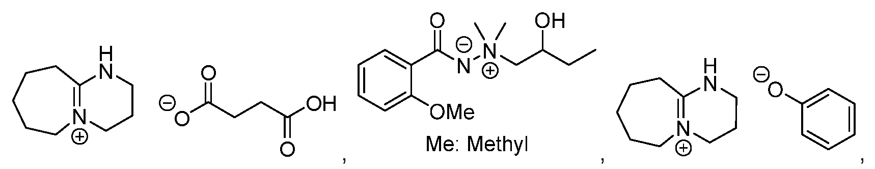


In einer Ausführungsform ist der basische Quencher N-(p-Nitrophenyl)-2,6-dimethylpiperidin. In einer Ausführungsform ist die Schutzschicht keine Fotolackschicht. In einer Ausführungsform ist die Fotolackschicht eine Positivton-Fotolackschicht. In einer Ausführungsform umfasst die Schutzschicht ein Polymer, das aus der Gruppe bestehend aus einem Polyacrylat, einem Polymethylmethacrylat, einem Polyfluoralkohol, einem Polyester, einem Polyimid, einem Polyether und einem Polyalkohol ausgewählt wird. In einer Ausführungsform enthält das Polymer keine säurelabilen Gruppen. In einer Ausführungsform umfasst das Verfahren ein Erwärmen der Fotolackschicht und der Schutzschicht auf eine Temperatur im Bereich von 40 °C bis 120 °C nach dem Bilden der Schutzschicht. In einer Ausführungsform umfasst das Verfahren ein Erwärmen der Fotolackschicht und der Schutzschicht auf eine Temperatur im Bereich von 50 °C bis 150 °C nach dem selektiven Belichten der Fotolackschicht.In one embodiment, the basic quencher is N-(p-nitrophenyl)-2,6-dimethylpiperidine. In one embodiment, the protective layer is not a photoresist layer. In one embodiment, the photoresist layer is a positive tone photoresist layer. In one embodiment, the protective layer comprises a polymer selected from the group consisting of a polyacrylate, a polymethyl methacrylate, a polyfluoroalcohol, a polyester, a polyimide, a polyether, and a polyalcohol. In one embodiment, the polymer does not contain any acid labile groups. In one embodiment, the method includes heating the photoresist layer and the protective layer to a temperature in the range of 40°C to 120°C after forming the protective layer. In one embodiment, the method includes heating the photoresist layer and the protective layer to a temperature in the range of 50°C to 150°C after selectively exposing the photoresist layer to light.
Eine andere Ausführungsform der Offenbarung ist ein Verfahren zur Bildung einer Fotolackstruktur, die ein Bilden einer Fotolackschicht mit einer Fotolackzusammensetzung über einem Substrat umfasst. Eine Schutzschicht, die ein Polymer ohne stickstoffhaltigen Rest, eine organische Säure, einen Fotosäuregenerator oder einen thermischen Säuregenerator umfasst, wird über der Fotolackschicht gebildet. Eine latente Struktur wird durch selektives Belichten der Fotolackschicht mit aktinischer Strahlung in der Fotolackschicht gebildet. Eine Säure wird in der Schutzschicht erzeugt, oder Säure in der Schutzschicht wird in die Fotolackschicht diffundiert. Die Schutzschicht wird entfernt, und die Fotolackschicht wird entwickelt, um eine Struktur in der Fotolackschicht zu bilden. In einer Ausführungsform werden Teile der Fotolackschicht, die nicht mit der aktinischen Strahlung belichtet wurden, während des Entwickelns der Fotolackschicht entfernt. In einer Ausführungsform wird die Säure, die in der Schutzschicht erzeugt wird, durch Belichten der Schutzschicht mit der aktinischen Strahlung erzeugt. In einer Ausführungsform wird die Säure, die in der Schutzschicht erzeugt wird, durch Erwärmen der Schutzschicht erzeugt. In einer Ausführungsform wird die Säure durch Erwärmen der Schutzschicht und der Fotolackschicht von der Schutzschicht in die Fotolackschicht diffundiert. In einer Ausführungsform handelt es sich bei dem Fotosäuregenerator um einen oder mehrere, die aus der Gruppe bestehend aus α-(Trifluormethylsulfonyloxy )-bicyclo[2.2.1]hept-5-en-2,3-dicarb-o-ximid (MDT), N-hydroxynaphthalimid (DDSN), Benzointosylat, t-Butylphenyl-α-(p-toluolsulfonyloxy)-acetat und t-Butyl-α-(p-toluolsulfonyloxy)-acetat, Triarylsulfonium und Diaryliodoniumhexafluorantimonaten, Hexafluorarsenaten, Trifluormethansulfonaten, Iodoniumperfluoroctansulfonat, N-Camphorsulfonyloxynaphthalimid, N-Pentafluorphenylsulfonyloxynaphthalimid, ionische Iodoniumsulfonaten, beispielsweise Daryliodonium (Alkyl- oder Aryl)sulfonat und Bis-(di-t-butylphenyl)iodoniumcamphanylsulfonat, Perfluoralkansulfonaten, beispielsweise Perfluorpentansulfonaten, Perfluoroctansulfonaten, Perfluormethansulfonaten, Aryl (z. B. Phenyl- oder Benzyl)triflaten, beispielsweise Triphenylsulfoniumtriflat oder Bis-(t-butylphenyl)iodoniumtriflat; Pyrogallolderivaten (z. B. Trimesylat von Pyrogallol), Trifluormethanesulfonatester von Hydroxyimiden, α,α'-Bis-sulfonyldiazomethanen, Sulfonatester von Nitro-substituierten Benzylalkoholen, Naphthochinon-4-diaziden, Alkyldisulfonen oder dergleichen ausgewählt werden. In einer Ausführungsform handelt es sich bei dem Fotosäuregenerator um einen oder mehrere, die ausgewählt werden aus der Gruppe bestehend aus:


In einer Ausführungsform wird die Fotolackschicht vor dem Bilden der Schutzschicht auf eine Temperatur im Bereich von 40 °C bis 120 °C erwärmt. In einer Ausführungsform umfasst die Fotolackschicht Metalloxid-Nanoteilchen. In einer Ausführungsform umfasst das Verfahren ein Erwärmen der Fotolackschicht und der Schutzschicht auf eine Temperatur im Bereich von 40 °C bis 120 °C nach dem Bilden der Schutzschicht. In einer Ausführungsform umfasst das Verfahren ein Erwärmen der Fotolackschicht und der Schutzschicht auf eine Temperatur im Bereich von 50 °C bis 150 °C nach dem selektiven Belichten der Fotolackschicht. In einer Ausführungsform handelt es sich bei dem thermischen Säuregenerator um einen oder mehrere, die ausgewählt werden aus der Gruppe bestehend aus
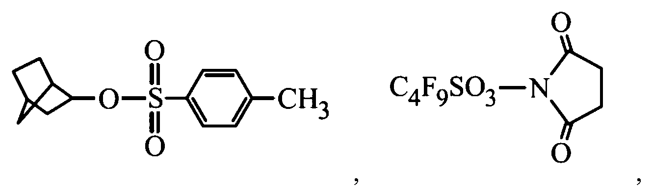


Eine andere Ausführungsform der Offenbarung ist ein Verfahren zur Herstellung eines Halbleiterbauelements, die ein Bilden einer Fotolackschicht über einem Substrat und Bilden einer Schutzschicht über der Fotolackschicht umfasst. Die Schutzschicht umfasst ein Polymer ohne stickstoffhaltigen Rest und einen basischen Quencher, eine organische Säure, einen Fotosäuregenerator oder einen thermischen Säuregenerator. Eine latente Struktur wird durch strukturartiges Belichten der Fotolackschicht mit Strahlung in der Fotolackschicht gebildet. Die Schutzschicht und die Fotolackschicht werden nach dem strukturartigen Belichten der Fotolackschicht mit Strahlung erwärmt. Die Schutzschicht wird entfernt, und die latente Struktur in der Fotolackschicht wird entwickelt, um eine Struktur in der Fotolackschicht zu bilden. In einer Ausführungsform werden die Schutzschicht und die Fotolackschicht während des Erwärmens der Schutzschicht und der Fotolackschicht auf eine Temperatur im Bereich von 50 °C bis 150 °C erwärmt. In einer Ausführungsform umfasst das Verfahren ein Erwärmen der Fotolackschicht und der Schutzschicht auf eine Temperatur im Bereich von 40 °C bis 120 °C vor dem Bilden der latenten Struktur in der Fotolackschicht. In einer Ausführungsform ist die Strahlung ein Elektronenstrahl, EUV oder DUV. In einer Ausführungsform enthält das Polymer keine säurelabilen Gruppen. In einer Ausführungsform wird die latente Struktur unter Verwendung eines basischen Entwicklers entwickelt. In einer Ausführungsform ist der basische Entwickler ein wässriger Tetramethylammoniumhydroxid-Entwickler. In einer Ausführungsform weist die Schutzschicht eine Dicke im Bereich von 0,1 nm bis 20 nm auf. In einer Ausführungsform liegt eine Konzentration des basischen Quenchers, der organischen Säure, der Fotosäuregenerators oder des thermischen Säuregenerators im Bereich von 0,1 Gew% bis 10 Gew% bezogen auf ein Gewicht des Polymers und des basischen Quenchers, einer organischen Säure, eines Fotosäuregenerators oder eines thermischen Säuregenerators. In einer Ausführungsform umfasst die Fotolackschicht Metalloxid-Nanoteilchen.Another embodiment of the disclosure is a method of manufacturing a semiconductor device that includes forming a photoresist layer over a substrate and forming a protective layer over the photoresist layer. The protective layer comprises a polymer having no nitrogen-containing residue and a basic quencher, an organic acid, a photoacid generator or a thermal acid generator. A latent structure is formed in the photoresist layer by patternwise exposing the photoresist layer to radiation. The protective layer and the photoresist layer are heated with radiation after patternwise exposing the photoresist layer. The protective layer is removed and the latent pattern in the photoresist layer is developed to form a pattern in the photoresist layer. In one embodiment, the protective layer and the photoresist layer are heated to a temperature in the range of 50°C to 150°C while heating the protective layer and the photoresist layer. In one embodiment, the method includes heating the photoresist layer and the protective layer to a temperature in the range of 40°C to 120°C prior to forming the latent structure in the photoresist layer. In one embodiment, the radiation is an electron beam, EUV or DUV. In one embodiment, the polymer does not contain any acid labile groups. In one embodiment, the latent structure is developed using a basic developer. In one embodiment, the base developer is aqueous tetramethylammo nium hydroxide developer. In one embodiment, the protective layer has a thickness in the range from 0.1 nm to 20 nm. In one embodiment, a concentration of the basic quencher, organic acid, photoacid generator, or thermal acid generator ranges from 0.1% to 10% by weight based on a weight of the polymer and the basic quencher, organic acid, photoacid generator, or a thermal acid generator. In one embodiment, the photoresist layer comprises metal oxide nanoparticles.
Eine Ausführungsform der Offenbarung ist ein Verfahren zur Herstellung einer Halbleiterbauelements, die ein Bilden einer Fotolackschicht mit einer Fotolackzusammensetzung über einem Substrat umfasst. Eine Schutzschicht, die ein Polymer und sekundäres oder tertiäres Amin, einen Fotosäuregenerator oder einen thermischen Basengenerator umfasst, wird über der Fotolackschicht gebildet. Die Fotolackschicht wird strukturartig mit Strahlung belichtet, um eine latente Struktur in der Fotolackschicht zu bilden. Die Schutzschicht und die Fotolackschicht werden erwärmt, um dadurch eine Base zu erzeugen oder Base in der Schutzschicht in die Fotolackschicht zu diffundieren. Die Fotolackschicht wird entwickelt, um eine Struktur in der Fotolackschicht zu bilden. In einer Ausführungsform ist die Schutzschicht keine Fotolackschicht. In einer Ausführungsform werden Teile der Schutzschicht, die mit der Strahlung strukturartig belichtet wurden, und Teile der Schutzschicht, die nicht mit der Strahlung belichtet wurden, während des Entwickelns der Fotoschicht entfernt. In einer Ausführungsform werden Teile der Fotolackschicht, die strukturartig mit der Strahlung belichtet wurden, während des Entwickelns der Fotolackschicht entfernt. In einer Ausführungsform erzeugt das strukturartige Belichten der Fotolackschicht mit Strahlung ferner die Base in der Schutzschicht. In einer Ausführungsform handelt es sich bei dem Fotobasengenerator um einen oder mehrere, die aus der Gruppe bestehend aus quartären Ammoniumdithiocarbamaten, α-Aminoketonen, Oximurethan-haltigen Molekülen, Dibenzophenonoximhexamethylendiurethan, Ammoniumtetraorganylboratsalzen, N-(2-Nitrobenzyloxycarbonyl)cyclischen Aminen und Kombinationen davon ausgewählt werden. In einer Ausführungsform handelt es sich bei dem thermischen Basengenerator um einen oder mehrere, die ausgewählt sind aus der Gruppe bestehend aus:


In einer Ausführungsform ist der thermische Basengenerator N-(p-Nitrophenyl)-2,6-dimethylpiperidin. In einer Ausführungsformen wird das sekundäre oder tertiäre Amin ausgewählt aus der Gruppe bestehend aus:


In einer Ausführungsformen weist der Fotobasengenerator die folgende Formel auf: R1-X-Y-N--(SO2)-Rf- M+, wobei R1 eine substituierte oder unsubstituierte alicyclische C5-C18-Gruppe ist, X eine zweiwertige Bindungsgruppe ist, Y eine lineare, verzweigte oder cyclische C2-C18-Alkylengruppe oder C6-C18-Arylengruppe ist, Rf eine C1-C5-Fuorkohlenwasserstoffgruppe ist, und M ein organisches Kation oder ein Metallkation ist.In one embodiment, the photobase generator has the following formula: R 1 -XYN-(SO 2 )-Rf- M + where R 1 is a substituted or unsubstituted C5-C18 alicyclic group, X is a divalent linking group, Y is a Rf is a C1-C5 hydrocarbyl group, and M is an organic cation or a metal cation.
Eine andere Ausführungsform der Offenbarung ist ein Verfahren zur Herstellung einer Halbleiterbauelements, die ein Bilden einer Fotolackschicht mit einer Fotolackzusammensetzung über einem Substrat umfasst. Eine Schutzschicht, die ein Polymer ohne stickstoffhaltigen Rest, und eine organische Säure, einen Fotosäuregenerator oder einen thermischen Säuregenerator umfasst, wird über der Fotolackschicht gebildet. Die Fotolackschicht wird strukturartig mit Strahlung belichtet, um eine latente Struktur in der Fotolackschicht zu bilden. Die Schutzschicht und die Fotolackschicht werden erwärmt, um dadurch eine Säure zu erzeugen oder Säure in der Schutzschicht in die Fotolackschicht zu diffundieren. Die Fotolackschicht wird entwickelt, um eine Struktur in der Fotolackschicht zu bilden. In einer Ausführungsform ist die Schutzschicht keine Fotolackschicht. In einer Ausführungsform werden Teile der Schutzschicht, die strukturartig mit der Strahlung belichtet wurden, und Teile der Schutzschicht, die nicht mit der Strahlung belichtet wurden, während des Entwickelns der Fotoschicht entfernt. In einer Ausführungsform werden Teile der Fotolackschicht, die nicht strukturartig mit der Strahlung belichtet wurden, während des Entwickelns der Fotolackschicht entfernt. In einer Ausführungsform erzeugt das strukturartige Belichten der Fotolackschicht mit Strahlung ferner die Säure in der Schutzschicht. In einer Ausführungsform handelt es sich bei dem thermischen Säuregenerator um einen oder mehrere, die ausgewählt werden aus der Gruppe bestehend aus


Claims (20)


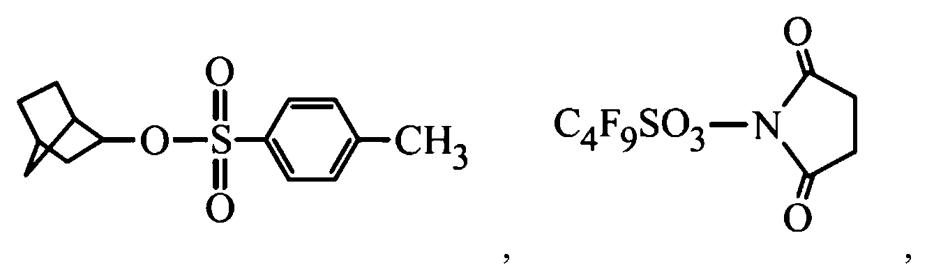


Applications Claiming Priority (4)
| Application Number | Priority Date | Filing Date | Title |
|---|---|---|---|
| US201962956018P | 2019-12-31 | 2019-12-31 | |
| US62/956,018 | 2019-12-31 | ||
| US17/098,238 | 2020-11-13 | ||
| US17/098,238 US12547075B2 (en) | 2020-11-13 | Method of forming photoresist pattern |
Publications (2)
| Publication Number | Publication Date |
|---|---|
| DE102020130523A1 DE102020130523A1 (en) | 2021-07-01 |
| DE102020130523B4 true DE102020130523B4 (en) | 2023-08-10 |
Family
ID=76310628
Family Applications (1)
| Application Number | Title | Priority Date | Filing Date |
|---|---|---|---|
| DE102020130523.0A Active DE102020130523B4 (en) | 2019-12-31 | 2020-11-19 | METHOD OF FORMING A PHOTORESIST STRUCTURE |
Country Status (3)
| Country | Link |
|---|---|
| US (1) | US12535739B2 (en) |
| DE (1) | DE102020130523B4 (en) |
| TW (1) | TWI774172B (en) |
Citations (1)
| Publication number | Priority date | Publication date | Assignee | Title |
|---|---|---|---|---|
| US20130089820A1 (en) | 2011-10-11 | 2013-04-11 | Shin-Etsu Chemical Co., Ltd. | Resist top coat composition and patterning process |
Family Cites Families (39)
| Publication number | Priority date | Publication date | Assignee | Title |
|---|---|---|---|---|
| JP3955384B2 (en) | 1998-04-08 | 2007-08-08 | Azエレクトロニックマテリアルズ株式会社 | Chemically amplified resist composition |
| US6673513B2 (en) * | 2000-01-19 | 2004-01-06 | Samsung Electronics Co., Ltd. | Photosensitive polymer including copolymer of alkyl vinyl ether and resist composition containing the same |
| US6838224B2 (en) | 2000-03-07 | 2005-01-04 | Shi-Etsu Chemical Co., Ltd. | Chemical amplification, positive resist compositions |
| JP4361527B2 (en) * | 2002-12-02 | 2009-11-11 | 東京応化工業株式会社 | Chemically amplified silicone-based positive photoresist composition, double-layer resist material using the same, and ladder-type silicone copolymer used therefor |
| EP1741730B1 (en) * | 2004-04-27 | 2010-05-12 | Tokyo Ohka Kogyo Co., Ltd. | Resist protecting film forming material for immersion exposure process and resist pattern forming method using the protecting film |
| JP4520245B2 (en) | 2004-08-17 | 2010-08-04 | セントラル硝子株式会社 | Method for producing topcoat film for lithography |
| JP4648087B2 (en) | 2005-05-25 | 2011-03-09 | キヤノン株式会社 | Deflector fabrication method, charged particle beam exposure apparatus, and device manufacturing method |
| US7566650B2 (en) | 2005-09-23 | 2009-07-28 | Stats Chippac Ltd. | Integrated circuit solder bumping system |
| US20070092829A1 (en) * | 2005-10-21 | 2007-04-26 | Christoph Noelscher | Photosensitive coating for enhancing a contrast of a photolithographic exposure |
| KR100940915B1 (en) * | 2008-03-13 | 2010-02-08 | 금호석유화학 주식회사 | Acid Generator for Chemical Amplified Resist Composition |
| JP5101541B2 (en) | 2008-05-15 | 2012-12-19 | 信越化学工業株式会社 | Pattern formation method |
| CN103257527B (en) * | 2008-08-27 | 2016-08-31 | 日立化成株式会社 | Photosensitive adhesive composition, film-like adhesive, adhesive sheet, bonding agent figure, semiconductor wafer and semiconductor device |
| US8647796B2 (en) | 2011-07-27 | 2014-02-11 | Taiwan Semiconductor Manufacturing Company, Ltd. | Photoactive compound gradient photoresist |
| US9484259B2 (en) | 2011-09-21 | 2016-11-01 | STATS ChipPAC Pte. Ltd. | Semiconductor device and method of forming protection and support structure for conductive interconnect structure |
| US9213234B2 (en) | 2012-06-01 | 2015-12-15 | Taiwan Semiconductor Manufacturing Company, Ltd. | Photosensitive material and method of lithography |
| US9256133B2 (en) | 2012-07-13 | 2016-02-09 | Taiwan Semiconductor Manufacturing Company, Ltd. | Apparatus and method for developing process |
| US9028915B2 (en) | 2012-09-04 | 2015-05-12 | Taiwan Semiconductor Manufacturing Company, Ltd. | Method of forming a photoresist layer |
| KR102195151B1 (en) | 2012-09-07 | 2020-12-24 | 닛산 가가쿠 가부시키가이샤 | Composition for forming resist upper layer film for lithography and method for manufacturing semiconductor device using same |
| JP6072510B2 (en) | 2012-10-31 | 2017-02-01 | ラピスセミコンダクタ株式会社 | Semiconductor device manufacturing method and semiconductor device |
| US9093530B2 (en) | 2012-12-28 | 2015-07-28 | Taiwan Semiconductor Manufacturing Company, Ltd. | Fin structure of FinFET |
| US9223220B2 (en) | 2013-03-12 | 2015-12-29 | Taiwan Semiconductor Manufacturing Company, Ltd. | Photo resist baking in lithography process |
| US8796666B1 (en) | 2013-04-26 | 2014-08-05 | Taiwan Semiconductor Manufacturing Company, Ltd. | MOS devices with strain buffer layer and methods of forming the same |
| JP6261285B2 (en) * | 2013-10-31 | 2018-01-17 | 富士フイルム株式会社 | Laminate, organic semiconductor manufacturing kit and organic semiconductor manufacturing resist composition |
| US9515172B2 (en) | 2014-01-28 | 2016-12-06 | Samsung Electronics Co., Ltd. | Semiconductor devices having isolation insulating layers and methods of manufacturing the same |
| US9548303B2 (en) | 2014-03-13 | 2017-01-17 | Taiwan Semiconductor Manufacturing Company, Ltd. | FinFET devices with unique fin shape and the fabrication thereof |
| JP2015211988A (en) | 2014-05-01 | 2015-11-26 | セイコーエプソン株式会社 | Mems structure, electronic apparatus and movable body |
| CN103972118A (en) | 2014-05-28 | 2014-08-06 | 江阴长电先进封装有限公司 | Forming method of metal cap of wafer-level copper pillar bump structure |
| WO2016136596A1 (en) | 2015-02-26 | 2016-09-01 | 富士フイルム株式会社 | Composition for forming upper layer film, method for forming pattern using same, and process for producing electronic device |
| KR101982559B1 (en) * | 2015-05-29 | 2019-05-27 | 후지필름 가부시키가이샤 | A pattern forming method, a resist pattern, a method of manufacturing an electronic device, and a composition for forming an upper layer film |
| US9536759B2 (en) | 2015-05-29 | 2017-01-03 | Taiwan Semiconductor Manufacturing Co., Ltd | Baking apparatus and method |
| US10007177B2 (en) | 2015-08-21 | 2018-06-26 | Taiwan Semiconductor Manufacturing Company, Ltd. | Method to define multiple layer patterns using double exposures |
| CN106556972B (en) | 2015-09-30 | 2021-07-27 | 罗门哈斯电子材料韩国有限公司 | Overcoat compositions and methods for photolithography |
| TWI692674B (en) | 2015-12-31 | 2020-05-01 | 日商住友電木股份有限公司 | Polymers derived from norbornadiene and maleic anhydride and use thereof |
| US9857684B2 (en) | 2016-03-17 | 2018-01-02 | Taiwan Semiconductor Manufacturing Co., Ltd. | Silicon-containing photoresist for lithography |
| JP6754424B2 (en) * | 2016-03-30 | 2020-09-09 | 富士フイルム株式会社 | Protective film forming composition, method for producing protective film forming composition, pattern forming method, and method for producing electronic device |
| KR102446132B1 (en) * | 2016-09-16 | 2022-09-22 | 닛산 가가쿠 가부시키가이샤 | protective film forming composition |
| US10241411B2 (en) * | 2016-10-31 | 2019-03-26 | Rohm And Haas Electronic Materials Llc | Topcoat compositions containing fluorinated thermal acid generators |
| US11127704B2 (en) | 2017-11-28 | 2021-09-21 | Taiwan Semiconductor Manufacturing Co., Ltd. | Semiconductor device with bump structure and method of making semiconductor device |
| CN110634755A (en) | 2018-06-22 | 2019-12-31 | 中芯国际集成电路制造(上海)有限公司 | Semiconductor structures and methods of forming them |
-
2020
- 2020-11-19 DE DE102020130523.0A patent/DE102020130523B4/en active Active
- 2020-12-29 TW TW109146739A patent/TWI774172B/en active
-
2023
- 2023-08-07 US US18/231,006 patent/US12535739B2/en active Active
Patent Citations (1)
| Publication number | Priority date | Publication date | Assignee | Title |
|---|---|---|---|---|
| US20130089820A1 (en) | 2011-10-11 | 2013-04-11 | Shin-Etsu Chemical Co., Ltd. | Resist top coat composition and patterning process |
Also Published As
| Publication number | Publication date |
|---|---|
| TW202138915A (en) | 2021-10-16 |
| US12535739B2 (en) | 2026-01-27 |
| TWI774172B (en) | 2022-08-11 |
| DE102020130523A1 (en) | 2021-07-01 |
| US20240077802A1 (en) | 2024-03-07 |
Similar Documents
| Publication | Publication Date | Title |
|---|---|---|
| DE102019126271B4 (en) | Photoresist composition and method of forming a photoresist pattern | |
| US11215924B2 (en) | Photoresist, developer, and method of forming photoresist pattern | |
| DE102020131427B4 (en) | Photoresist composition and method of producing photoresist structure | |
| DE102019128448A1 (en) | Protective composition and method for forming a photoresist structure | |
| US20210311388A1 (en) | Photoresist composition and method of manufacturing semiconductor device | |
| US20230384673A1 (en) | Photoresist composition and method of manufacturing a semiconductor device | |
| DE102020124247A1 (en) | PHOTO LACQUER DEVELOPER AND PROCESS FOR DEVELOPING PHOTO LACQUER | |
| KR102684029B1 (en) | Method of forming photoresist pattern | |
| US12085855B2 (en) | Resin, photoresist composition, and method of manufacturing semiconductor device | |
| DE102020130523B4 (en) | METHOD OF FORMING A PHOTORESIST STRUCTURE | |
| US11703765B2 (en) | Photoresist composition and method of manufacturing a semiconductor device | |
| US12135502B2 (en) | Resin, photoresist composition, and method of manufacturing semiconductor device | |
| US12547075B2 (en) | Method of forming photoresist pattern | |
| US12379659B2 (en) | Photoresist composition and method of manufacturing a semiconductor device | |
| DE102021100839A1 (en) | FOTORESIST COMPOSITION AND METHOD OF MAKING A PHOTORESIST STRUCTURE | |
| US12504693B2 (en) | Photoresist composition and method of manufacturing a semiconductor device | |
| US20230384675A1 (en) | Underlayer composition and method of manufacturing a semiconductor device | |
| DE102023107991A1 (en) | METHOD FOR PRODUCING A SEMICONDUCTOR DEVICE | |
| CN113050374A (en) | Photoresist composition and method for manufacturing semiconductor device |
Legal Events
| Date | Code | Title | Description |
|---|---|---|---|
| R012 | Request for examination validly filed | ||
| R016 | Response to examination communication | ||
| R018 | Grant decision by examination section/examining division | ||
| R020 | Patent grant now final |