DE102020130196A1 - Refrigeration system for a motor vehicle with an additional heat exchanger as an undercooling section, motor vehicle with such a refrigeration system - Google Patents
Refrigeration system for a motor vehicle with an additional heat exchanger as an undercooling section, motor vehicle with such a refrigeration system Download PDFInfo
- Publication number
- DE102020130196A1 DE102020130196A1 DE102020130196.0A DE102020130196A DE102020130196A1 DE 102020130196 A1 DE102020130196 A1 DE 102020130196A1 DE 102020130196 A DE102020130196 A DE 102020130196A DE 102020130196 A1 DE102020130196 A1 DE 102020130196A1
- Authority
- DE
- Germany
- Prior art keywords
- heat exchanger
- refrigeration system
- refrigerant
- motor vehicle
- coolant
- Prior art date
- Legal status (The legal status is an assumption and is not a legal conclusion. Google has not performed a legal analysis and makes no representation as to the accuracy of the status listed.)
- Pending
Links
Images


Classifications
-
- B—PERFORMING OPERATIONS; TRANSPORTING
- B60—VEHICLES IN GENERAL
- B60H—ARRANGEMENTS OF HEATING, COOLING, VENTILATING OR OTHER AIR-TREATING DEVICES SPECIALLY ADAPTED FOR PASSENGER OR GOODS SPACES OF VEHICLES
- B60H1/00—Heating, cooling or ventilating [HVAC] devices
- B60H1/00642—Control systems or circuits; Control members or indication devices for heating, cooling or ventilating devices
- B60H1/00814—Control systems or circuits characterised by their output, for controlling particular components of the heating, cooling or ventilating installation
- B60H1/00878—Control systems or circuits characterised by their output, for controlling particular components of the heating, cooling or ventilating installation the components being temperature regulating devices
- B60H1/00899—Controlling the flow of liquid in a heat pump system
- B60H1/00921—Controlling the flow of liquid in a heat pump system where the flow direction of the refrigerant does not change and there is an extra subcondenser, e.g. in an air duct
-
- B—PERFORMING OPERATIONS; TRANSPORTING
- B60—VEHICLES IN GENERAL
- B60H—ARRANGEMENTS OF HEATING, COOLING, VENTILATING OR OTHER AIR-TREATING DEVICES SPECIALLY ADAPTED FOR PASSENGER OR GOODS SPACES OF VEHICLES
- B60H1/00—Heating, cooling or ventilating [HVAC] devices
- B60H1/00271—HVAC devices specially adapted for particular vehicle parts or components and being connected to the vehicle HVAC unit
- B60H1/00278—HVAC devices specially adapted for particular vehicle parts or components and being connected to the vehicle HVAC unit for the battery
-
- B—PERFORMING OPERATIONS; TRANSPORTING
- B60—VEHICLES IN GENERAL
- B60H—ARRANGEMENTS OF HEATING, COOLING, VENTILATING OR OTHER AIR-TREATING DEVICES SPECIALLY ADAPTED FOR PASSENGER OR GOODS SPACES OF VEHICLES
- B60H1/00—Heating, cooling or ventilating [HVAC] devices
- B60H1/32—Cooling devices
- B60H1/3204—Cooling devices using compression
- B60H1/323—Cooling devices using compression characterised by comprising auxiliary or multiple systems, e.g. plurality of evaporators, or by involving auxiliary cooling devices
-
- F—MECHANICAL ENGINEERING; LIGHTING; HEATING; WEAPONS; BLASTING
- F25—REFRIGERATION OR COOLING; COMBINED HEATING AND REFRIGERATION SYSTEMS; HEAT PUMP SYSTEMS; MANUFACTURE OR STORAGE OF ICE; LIQUEFACTION SOLIDIFICATION OF GASES
- F25B—REFRIGERATION MACHINES, PLANTS OR SYSTEMS; COMBINED HEATING AND REFRIGERATION SYSTEMS; HEAT PUMP SYSTEMS
- F25B6/00—Compression machines, plants or systems, with several condenser circuits
- F25B6/04—Compression machines, plants or systems, with several condenser circuits arranged in series
-
- B—PERFORMING OPERATIONS; TRANSPORTING
- B60—VEHICLES IN GENERAL
- B60H—ARRANGEMENTS OF HEATING, COOLING, VENTILATING OR OTHER AIR-TREATING DEVICES SPECIALLY ADAPTED FOR PASSENGER OR GOODS SPACES OF VEHICLES
- B60H1/00—Heating, cooling or ventilating [HVAC] devices
- B60H1/00271—HVAC devices specially adapted for particular vehicle parts or components and being connected to the vehicle HVAC unit
- B60H2001/00307—Component temperature regulation using a liquid flow
-
- B—PERFORMING OPERATIONS; TRANSPORTING
- B60—VEHICLES IN GENERAL
- B60H—ARRANGEMENTS OF HEATING, COOLING, VENTILATING OR OTHER AIR-TREATING DEVICES SPECIALLY ADAPTED FOR PASSENGER OR GOODS SPACES OF VEHICLES
- B60H1/00—Heating, cooling or ventilating [HVAC] devices
- B60H1/00642—Control systems or circuits; Control members or indication devices for heating, cooling or ventilating devices
- B60H1/00814—Control systems or circuits characterised by their output, for controlling particular components of the heating, cooling or ventilating installation
- B60H1/00878—Control systems or circuits characterised by their output, for controlling particular components of the heating, cooling or ventilating installation the components being temperature regulating devices
- B60H2001/00949—Control systems or circuits characterised by their output, for controlling particular components of the heating, cooling or ventilating installation the components being temperature regulating devices comprising additional heating/cooling sources, e.g. second evaporator
-
- F—MECHANICAL ENGINEERING; LIGHTING; HEATING; WEAPONS; BLASTING
- F25—REFRIGERATION OR COOLING; COMBINED HEATING AND REFRIGERATION SYSTEMS; HEAT PUMP SYSTEMS; MANUFACTURE OR STORAGE OF ICE; LIQUEFACTION SOLIDIFICATION OF GASES
- F25B—REFRIGERATION MACHINES, PLANTS OR SYSTEMS; COMBINED HEATING AND REFRIGERATION SYSTEMS; HEAT PUMP SYSTEMS
- F25B2400/00—General features or devices for refrigeration machines, plants or systems, combined heating and refrigeration systems or heat-pump systems, i.e. not limited to a particular subgroup of F25B
- F25B2400/04—Refrigeration circuit bypassing means
- F25B2400/0409—Refrigeration circuit bypassing means for the evaporator
-
- F—MECHANICAL ENGINEERING; LIGHTING; HEATING; WEAPONS; BLASTING
- F25—REFRIGERATION OR COOLING; COMBINED HEATING AND REFRIGERATION SYSTEMS; HEAT PUMP SYSTEMS; MANUFACTURE OR STORAGE OF ICE; LIQUEFACTION SOLIDIFICATION OF GASES
- F25B—REFRIGERATION MACHINES, PLANTS OR SYSTEMS; COMBINED HEATING AND REFRIGERATION SYSTEMS; HEAT PUMP SYSTEMS
- F25B2400/00—General features or devices for refrigeration machines, plants or systems, combined heating and refrigeration systems or heat-pump systems, i.e. not limited to a particular subgroup of F25B
- F25B2400/05—Compression system with heat exchange between particular parts of the system
- F25B2400/054—Compression system with heat exchange between particular parts of the system between the suction tube of the compressor and another part of the cycle
-
- F—MECHANICAL ENGINEERING; LIGHTING; HEATING; WEAPONS; BLASTING
- F25—REFRIGERATION OR COOLING; COMBINED HEATING AND REFRIGERATION SYSTEMS; HEAT PUMP SYSTEMS; MANUFACTURE OR STORAGE OF ICE; LIQUEFACTION SOLIDIFICATION OF GASES
- F25B—REFRIGERATION MACHINES, PLANTS OR SYSTEMS; COMBINED HEATING AND REFRIGERATION SYSTEMS; HEAT PUMP SYSTEMS
- F25B2700/00—Sensing or detecting of parameters; Sensors therefor
- F25B2700/19—Pressures
- F25B2700/193—Pressures of the compressor
- F25B2700/1931—Discharge pressures
-
- F—MECHANICAL ENGINEERING; LIGHTING; HEATING; WEAPONS; BLASTING
- F25—REFRIGERATION OR COOLING; COMBINED HEATING AND REFRIGERATION SYSTEMS; HEAT PUMP SYSTEMS; MANUFACTURE OR STORAGE OF ICE; LIQUEFACTION SOLIDIFICATION OF GASES
- F25B—REFRIGERATION MACHINES, PLANTS OR SYSTEMS; COMBINED HEATING AND REFRIGERATION SYSTEMS; HEAT PUMP SYSTEMS
- F25B2700/00—Sensing or detecting of parameters; Sensors therefor
- F25B2700/19—Pressures
- F25B2700/193—Pressures of the compressor
- F25B2700/1933—Suction pressures
-
- F—MECHANICAL ENGINEERING; LIGHTING; HEATING; WEAPONS; BLASTING
- F25—REFRIGERATION OR COOLING; COMBINED HEATING AND REFRIGERATION SYSTEMS; HEAT PUMP SYSTEMS; MANUFACTURE OR STORAGE OF ICE; LIQUEFACTION SOLIDIFICATION OF GASES
- F25B—REFRIGERATION MACHINES, PLANTS OR SYSTEMS; COMBINED HEATING AND REFRIGERATION SYSTEMS; HEAT PUMP SYSTEMS
- F25B2700/00—Sensing or detecting of parameters; Sensors therefor
- F25B2700/21—Temperatures
- F25B2700/2115—Temperatures of a compressor or the drive means therefor
- F25B2700/21151—Temperatures of a compressor or the drive means therefor at the suction side of the compressor
-
- F—MECHANICAL ENGINEERING; LIGHTING; HEATING; WEAPONS; BLASTING
- F25—REFRIGERATION OR COOLING; COMBINED HEATING AND REFRIGERATION SYSTEMS; HEAT PUMP SYSTEMS; MANUFACTURE OR STORAGE OF ICE; LIQUEFACTION SOLIDIFICATION OF GASES
- F25B—REFRIGERATION MACHINES, PLANTS OR SYSTEMS; COMBINED HEATING AND REFRIGERATION SYSTEMS; HEAT PUMP SYSTEMS
- F25B2700/00—Sensing or detecting of parameters; Sensors therefor
- F25B2700/21—Temperatures
- F25B2700/2115—Temperatures of a compressor or the drive means therefor
- F25B2700/21152—Temperatures of a compressor or the drive means therefor at the discharge side of the compressor
Landscapes
- Engineering & Computer Science (AREA)
- Physics & Mathematics (AREA)
- Mechanical Engineering (AREA)
- Thermal Sciences (AREA)
- General Engineering & Computer Science (AREA)
- Air-Conditioning For Vehicles (AREA)
Abstract
Beschrieben wird eine Kälteanlage (10) für ein Kraftfahrzeug, wobei die Kälteanlage (10) um-fasst: einen Kältemittelverdichter (12); einen ersten, indirekt wirkenden Wärmeübertrager (18), der bezogen auf eine Strömungsrichtung von Kältemittel stromabwärts von dem Kältemittelverdichter (12) angeordnet ist und in dem die Kondensation von Kältemittel erfolgt; und wenigstens einen Verdampfer (22) mit einer dem Verdampfer (22) zugeordneten Ventileinrichtung (AE2), insbesondere einem zugeordneten Expansionsventil. Dabei ist vorgesehen, dass bezogen auf die Strömungsrichtung von Kältemittel in einem Kühlbetrieb der Kälteanlage (10) stromabwärts von dem ersten Wärmeübertrager (18) wenigstens ein zweiter, direkt oder indirekt wirkender Wärmeübertrager (40) angeordnet ist, in dem eine weitere Ab-/Auskühlung bzw. Unterkühlung des Kältemittels erfolgt.A refrigeration system (10) for a motor vehicle is described, the refrigeration system (10) comprising: a refrigerant compressor (12); a first, indirectly acting heat exchanger (18) which is arranged downstream of the refrigerant compressor (12) in relation to a flow direction of refrigerant and in which the condensation of refrigerant takes place; and at least one evaporator (22) with a valve device (AE2) assigned to the evaporator (22), in particular an assigned expansion valve. It is provided that at least one second, directly or indirectly acting heat exchanger (40) is arranged downstream of the first heat exchanger (18) with respect to the direction of flow of refrigerant in cooling mode of the refrigeration system (10), in which further cooling or supercooling of the refrigerant takes place.
Description
Die Erfindung betrifft eine Kälteanlage für ein Kraftfahrzeug, wobei die Kälteanlage umfasst: einen Kältemittelverdichter; einen ersten, indirekt wirkenden Wärmeübertrager, der bezogen auf eine Strömungsrichtung von Kältemittel stromabwärts von dem Kältemittelverdichter angeordnet ist und in dem eine Kühlung und/oder Kondensation von Kältemittel erfolgt; und wenigstens einen Verdampfer mit einer dem Verdampfer zugeordneten Ventileinrichtung, insbesondere einem zugeordneten Expansionsventil.The invention relates to a refrigeration system for a motor vehicle, the refrigeration system comprising: a refrigerant compressor; a first, indirectly acting heat exchanger, which is arranged downstream of the refrigerant compressor in relation to a flow direction of refrigerant and in which cooling and/or condensation of refrigerant takes place; and at least one evaporator with a valve device assigned to the evaporator, in particular an assigned expansion valve.
Aus der
Aus der
Es hat sich gezeigt, dass bei Kälteanlagen für elektrisch angetriebene Kraftfahrzeuge mit einem indirekt wirkenden ersten Wärmeübertrager, der auch als äußerer Wärmeübertrager bezeichnet werden kann, für einen leistungsoptimierten Betrieb ein höherer Kältemittelmassenstrom und damit eine höhere Fördermenge am Kältemittelverdichter erforderlich ist. Ferner kann eine erhöhte Fördermenge am Kältemittelverdichter unter Umständen akustisch in einem Innenraum des Fahrzeugs wahrgenommen werden (hohe Verdichterleistung), was unerwünscht ist. Weiterhin arbeiten solche (indirekten) Systeme zumeist bei höheren Druckverhältnissen, welche sich wiederum nachteilig auf die Systemeffizienz auswirken.It has been shown that in refrigeration systems for electrically powered motor vehicles with an indirectly acting first heat exchanger, which can also be referred to as an external heat exchanger, a higher refrigerant mass flow and thus a higher flow rate at the refrigerant compressor is required for performance-optimized operation. Furthermore, an increased delivery volume at the refrigerant compressor can sometimes be heard acoustically in an interior of the vehicle (high compressor output), which is undesirable. Furthermore, such (indirect) systems usually work at higher pressure ratios, which in turn have an adverse effect on system efficiency.
Die der Erfindung zu Grunde liegende Aufgabe wird darin gesehen, eine Kälteanlage anzugeben, bei der unter Beibehaltung der geforderten Systemleistung die Effizienz des Betriebs verbessert werden kann.The object on which the invention is based is seen as specifying a refrigeration system in which the efficiency of operation can be improved while maintaining the required system performance.
Diese Aufgabe wird gelöst durch eine Kälteanlage mit den Merkmalen des Patentanspruchs 1 und durch eine Kraftfahrzeug mit einer solchen Kälteanlage. Vorteilhafte Ausgestaltungen mit zweckmäßigen Weiterbildungen sind in den abhängigen Patentansprüchen angegeben.This object is achieved by a refrigeration system with the features of patent claim 1 and by a motor vehicle with such a refrigeration system. Advantageous configurations with expedient developments are specified in the dependent patent claims.
Vorgeschlagen wird also eine Kälteanlage für ein Kraftfahrzeug, wobei die Kälteanlage umfasst: einen Kältemittelverdichter; einen ersten, indirekt wirkenden Wärmeübertrager, der bezogen auf eine Strömungsrichtung von Kältemittel stromabwärts von dem Kältemittelverdichter angeordnet ist und in dem eine Kühlung und/oder Kondensation von Kältemittel erfolgt; und wenigstens einen Verdampfer mit einer dem Verdampfer zugeordneten Ventileinrichtung, insbesondere einem zugeordneten Expansionsventil. Dabei ist vorgesehen, dass bezogen auf die Strömungsrichtung von Kältemittel in einem Kühlbetrieb (AC-Betrieb) der Kälteanlage stromabwärts von dem ersten Wärmeübertrager wenigstens ein zweiter, direkt oder indirekt wirkender Wärmeübertrager angeordnet ist, in dem eine weitere Ab-/Auskühlung bzw. Unterkühlung des Kältemittels erfolgt.A refrigeration system for a motor vehicle is therefore proposed, the refrigeration system comprising: a refrigerant compressor; a first, indirectly acting heat exchanger, which is arranged downstream of the refrigerant compressor in relation to a flow direction of refrigerant and in which cooling and/or condensation of refrigerant takes place; and at least one evaporator with a valve device assigned to the evaporator, in particular an assigned expansion valve. It is provided that at least one second, directly or indirectly acting heat exchanger is arranged downstream of the first heat exchanger with respect to the direction of flow of refrigerant in cooling mode (AC mode) of the refrigeration system, in which further cooling/cooling or supercooling of the refrigerant takes place.
In Bezug auf die Wirkungsweise der hier beschriebenen Wärmeübertrager wird darauf hingewiesen, dass ein direkt wirkender Wärmeübertrager von Luft, insbesondere Umgebungsluft, direkt beaufschlagt ist, also eine direkte Wärmeübertragung zwischen Luft und Kältemittel erfolgt. Ein indirekt wirkender Wärmeübertrager weist einen Kühlmittelkreislauf auf, wobei die Wärmeübertragung zwischen Kühlmittel und Kältemittel erfolgt. Das Kühlmittel kann beispielsweise in einem von (Umgebungs-) Luft beaufschlagten im Kühlmittelkreislauf enthaltenen Kühler abgekühlt werden.With regard to the mode of operation of the heat exchanger described here, it is pointed out that air, in particular ambient air, acts directly on a directly acting heat exchanger, ie direct heat transfer takes place between air and refrigerant. An indirectly acting heat exchanger has a coolant circuit, with the heat being transferred between coolant and refrigerant. The coolant can be cooled, for example, in a cooler contained in the coolant circuit and acted upon by (ambient) air.
Durch die Einbindung mindestens einen zweiten, direkt oder indirekt wirkenden Wärmeübertragers kann die Effizienz der Kälteanlage verbessert werden. Durch die weitere Ab-/Auskühlung bzw. Unterkühlung kann das Temperaturniveau des Kältemittels weiter gesenkt werden, so dass es andernorts im Kältemittelkreislauf, beispielsweise im Verdampfer, mehr Wärme aufgenommen werden kann. Mit anderen Worten wird durch den zweiten Wärmeübertrager, der eine Unterkühlung des Kältemittels bewirkt, ein Enthalpiezugewinn erreicht, wodurch zum Erzielen derselben Kälteleistung ein reduzierter Kältemittelmassenstrom erforderlich wird. Durch die Ausgestaltung der erweiterten bzw. zusätzlichen Ab-/Auskühlstrecke bzw. Unterkühlstrecke als direkt oder indirekt wirkender Wärmeübertrager, können die den Wärmeübertrager beaufschlagende Luft oder das im Wärmeübertrager zirkulierende Kühlmittel als Wärmesenken wirken, die dem Kältemittel effektiv Wärme entziehen können.The efficiency of the refrigeration system can be improved by integrating at least one second, directly or indirectly acting heat exchanger. The temperature level of the refrigerant can be lowered further as a result of the further cooling down/cooling down or supercooling, so that more heat can be absorbed elsewhere in the refrigerant circuit, for example in the evaporator. In other words, the second heat exchanger, which causes supercooling of the refrigerant, achieves an enthalpy gain, as a result of which a reduced refrigerant mass flow is required to achieve the same refrigeration capacity. Due to the design of the extended or additional cooling/cooling section or sub-cooling section as a directly or indirectly acting heat exchanger, the air acting on the heat exchanger or the coolant circulating in the heat exchanger can act as heat sinks that can effectively extract heat from the coolant.
Bei der Kälteanlage kann der erste indirekt wirkende Wärmeübertrager mit einem ersten Kühlmittelkreislauf verbunden sein, in dem ein erstes Kühlmittel zirkuliert, und der zweite Wärmeübertrager kann als indirekt wirkender Wärmeübertrager mit einem zweiten Kühlmittelkreislauf verbunden sein, in dem ein zweites Kühlmittel zirkuliert. Das zweite Kühlmittel kann in seiner Zusammensetzung dem ersten Kühlmittel entsprechen. Kreislaufbezogen kann das zweite Kühlmittel unabhängig von dem ersten Kühlmittel zirkulieren. Mit anderen Worten zirkulieren das erste und das zweite Kühlmittel in getrennten Kühlm ittelkreisen.In the refrigeration system, the first indirectly acting heat exchanger can be connected to a first coolant circuit in which a first coolant circulates, and the second heat exchanger can be connected as an indirect heat exchanger to a second coolant circuit in which a second coolant circulates. The composition of the second coolant can correspond to that of the first coolant. In relation to the circuit, the second coolant can circulate independently of the first coolant. With other words The first and second coolants circulate in separate coolant circuits.
Die Kälteanlage kann wenigstens einen dritten Wärmeübertrager, insbesondere einen Chiller, aufweisen, der strömungstechnisch parallel oder in Reihe zu dem Verdampfer angeordnet ist. Insbesondere die strömungstechnisch parallel Anordnung bietet dabei für den Betrieb der Kälteanlage flexible Betriebseinstellungen, weil Kältemittel wahlweise durch den Verdampfer oder/und den dritten Wärmeübertrager (Chiller) geleitet werden kann. Der dritte Wärmeübertrager kann insbesondere dazu eingerichtet sein, mittels eines Kühlmittelkreislaufs Abwärme von wenigstens einer elektrischen Komponente des Kraftfahrzeugs, wie beispielsweise Hochvoltbatterie, ab-zuführen, wobei das erwärmte Kühlmittel die Wärme im dritten Wärmeübertrager bzw. Chiller an das zu verdampfende Kältemittel abgeben kann.The refrigeration system can have at least one third heat exchanger, in particular a chiller, which in terms of flow is arranged parallel to or in series with the evaporator. In particular, the parallel arrangement in terms of flow technology offers flexible operating settings for the operation of the refrigeration system, because refrigerant can be routed through the evaporator and/or the third heat exchanger (chiller) as desired. The third heat exchanger can in particular be set up to dissipate waste heat from at least one electrical component of the motor vehicle, such as a high-voltage battery, by means of a coolant circuit, with the heated coolant being able to give off the heat in the third heat exchanger or chiller to the refrigerant to be evaporated.
Bei der Kälteanlage kann der zweite Kühlmittelkreislauf mit dem dritten Wärmeübertrager, insbesondere Chiller, verbunden sein. Dabei kann der zweite Kühlmittelkreislauf mit dem zweiten Wärmeübertrager und dem dritten Wärmeübertrager, insbesondere Chiller, derart ausgebildet sein, dass der zweite Wärmeübertrager mit Kühlmittel beaufschlagt ist, das im Wesentlichen die tiefste Temperatur im zweiten Kühlmittelkreislauf aufweist. Mit anderen Worten ist der zweite Wärmeübertrager, der für die Unterkühlung von Kältemittel eingesetzt wird, in Strömungsrichtung des Kühlmittels dem dritten Wärmeübertrager bzw. Chiller als nächste Komponente nachgeschaltet. Man kann auch davon sprechen, dass der zweite Wärmeübertrager dem dritten Wärmeübertrager bzw. Chiller direkt nachgeschaltet ist. Hierdurch kann gewährleistet werden, dass im zweiten Wärmeübertrager stets Kühlmittel mit möglichst geringer Temperatur anliegt, so dass dem Kältemittel Wärme entzogen und dieses aus-/ abgekühlt bzw. unterkühlt werden kann.In the refrigeration system, the second coolant circuit can be connected to the third heat exchanger, in particular a chiller. The second coolant circuit can be designed with the second heat exchanger and the third heat exchanger, in particular a chiller, in such a way that the second heat exchanger is charged with coolant that essentially has the lowest temperature in the second coolant circuit. In other words, the second heat exchanger, which is used for the supercooling of refrigerant, is the next component downstream of the third heat exchanger or chiller in the flow direction of the coolant. One can also say that the second heat exchanger is directly downstream of the third heat exchanger or chiller. In this way, it can be ensured that coolant with the lowest possible temperature is always present in the second heat exchanger, so that heat can be withdrawn from the coolant and this can be cooled off or supercooled.
Die Kälteanlage kann in dem Kältemittelkreislauf einen Bypassabschnitt aufweisen, der dazu eingerichtet ist, den zweiten Wärmeübertrager zu umgehen. Hierdurch kann ein für die Ab-/Auskühlung bzw. Unterkühlung von Kältemitteln einzusetzender zweiter Wärmeübertrager auch in einer Kälteanlage mit Wärmepumpenfunktion eingesetzt werden, wobei in einem Wärmepumpenbetrieb keine Unterkühlung stattfindet bzw. erforderlich ist.The refrigeration system can have a bypass section in the refrigerant circuit, which is set up to bypass the second heat exchanger. As a result, a second heat exchanger to be used for cooling down/cooling down or subcooling of refrigerants can also be used in a refrigeration system with a heat pump function, with no subcooling taking place or being necessary in heat pump operation.
Dabei kann der Bypassabschnitt zwischen dem ersten Wärmeübertrager und dem zweiten Wärmeübertrager abzweigen und bezogen auf die Strömungsrichtung von Kältemittel in einem Kühlbetrieb der Kälteanlage stromabwärts von dem zweiten Wärmeübertrager mit dem Kältemittelkreislauf verbunden sein.The bypass section can branch off between the first heat exchanger and the second heat exchanger and be connected to the refrigerant circuit downstream of the second heat exchanger in relation to the flow direction of refrigerant in cooling operation of the refrigeration system.
Ergänzend kann stromabwärts von dem zweiten Wärmeübertrager und stromaufwärts von der Verbindung des Bypassabschnitts mit dem Kältemittkreislauf ein Absperrorgan, insbesondere als Rückschlagventil ausgeführt, angeordnet sein. Hierdurch kann ein Rückströmen von Kältemittel vermieden werden, wenn das Kältemittel den zweiten Wärmeübertrager umgehen soll.In addition, a shut-off device, in particular designed as a check valve, can be arranged downstream of the second heat exchanger and upstream of the connection of the bypass section to the refrigerant circuit. This can prevent refrigerant from flowing back if the refrigerant is to bypass the second heat exchanger.
Zwischen dem Abzweig des Bypassabschnitts und dem zweiten Wärmeübertrager kann eine Ventileinrichtung, insbesondere ein Absperrventil, angeordnet sein, die dazu eingerichtet ist, den Kältemittelstrom durch den zweiten Wärmeübertrager freizugeben oder zu verhindern. Weiter kann der Bypassabschnitt eine Bypassventileinrichtung, insbesondere ein Absperrventil, aufweisen, die dazu eingerichtet ist, den Kältemittelstrom durch den Bypassabschnitt freizugeben oder zu verhindern. Mittels wenigstens einer der vorgenannten Ventileinrichtungen ist es möglich, den Bypassabschnitt bzw. den zweiten Wärmeübertrager in den Kältemittelkreislauf einzubinden oder von der Durchströmung mit Kältemittel auszuschließen. Dies unterstützt die Anwendung bzw. den Einbau eines zweiten Wärmeübetragers für die Unterkühlung von Kältemittel in einer Kälteanlage mit Wärmepumpenfunktion.A valve device, in particular a shut-off valve, can be arranged between the branch of the bypass section and the second heat exchanger, which is set up to release or prevent the flow of refrigerant through the second heat exchanger. Furthermore, the bypass section can have a bypass valve device, in particular a shut-off valve, which is set up to release or prevent the flow of refrigerant through the bypass section. By means of at least one of the aforementioned valve devices, it is possible to integrate the bypass section or the second heat exchanger into the refrigerant circuit or to exclude it from the flow of refrigerant. This supports the use or installation of a second heat exchanger for the subcooling of refrigerants in a refrigeration system with a heat pump function.
In einer weiteren Ausgestaltung der Bypassventileinrichtung als stufenlosverstellbares Ventil können neben der Funktionsabbildung vollständiges Sperren bzw. Durchströmen auch beliebige Zwischenstellung ermöglicht werden, die ihrerseits für ein erweitertes Wärmemanagement innerhalb der Prozessführung eingesetzt werden können. Dabei wird ein gleichzeitiges Durchströmen beider Kältemittelstränge ermöglicht mit verschiedenen Kältemittelverteilungen.In a further embodiment of the bypass valve device as an infinitely variable valve, any intermediate position can be made possible in addition to the functional depiction of complete blocking or flow, which in turn can be used for extended heat management within the process control. Simultaneous flow through both refrigerant lines is made possible with different refrigerant distributions.
Der zweite Wärmeübertrager kann dabei luftseitig mit einem (stufenlos) verschließbaren Kühllufteintritt versehen werden, der seinerseits speziell bei niedrigeren Umgebungstemperaturen besagte Kältemittelverteilung positiv beeinflussen kann.The second heat exchanger can be provided on the air side with a (continuously) closable cooling air inlet, which in turn can have a positive effect on said refrigerant distribution, especially at lower ambient temperatures.
Ein Kraftfahrzeug, insbesondere ein zumindest teilweise elektrisch angetriebenes Kraftfahrzeug, kann mit einer oben beschriebenen Kälteanlage ausgerüstet sein. Bei einem Elektrofahrzeug kann der effiziente Betrieb der Kälteanlage unter Einbindung eines zweiten Wärmeübertragers als Ab-/- Auskühlstrecke bzw. Unterkühlungsstrecke zu Stromeinsparungen führen, so dass hierdurch eine größere Reichweite des Elektrofahrzeugs erzielt werden kann.A motor vehicle, in particular an at least partially electrically driven motor vehicle, can be equipped with a refrigeration system as described above. In an electric vehicle, the efficient operation of the refrigeration system with the integration of a second heat exchanger as a cooling/cooling section or supercooling section can lead to electricity savings, so that a greater range of the electric vehicle can be achieved.
Bei dem Kraftfahrzeug kann der zweite Wärmeübertrager als direkt wirkender Wärmeübertrager bezogen auf einen Luftstrom einem Kühlerpaket des Kraftfahrzeugs vorgeschaltet sein. Alternativ kann der zweite Wärmeübertrager als direkt wirkender Wärmeübertrager im Bereich einer Schürze des Kraftfahrzeugs, insbesondere in einem separat ausgeführten Luftkanal, angeordnet sein. Ferner kann der zweite Wärmeübertrager seitlich oder/und unterhalb eines üblicherweise mittig angeordneten Kühlers bzw. Kühlerpakets angeordnet bzw. angebracht sein.In the motor vehicle, the second heat exchanger can be connected upstream of a cooler package of the motor vehicle as a directly acting heat exchanger based on an air flow. Alternatively can the second heat exchanger can be arranged as a directly acting heat exchanger in the area of an apron of the motor vehicle, in particular in a separately designed air duct. Furthermore, the second heat exchanger can be arranged or attached to the side and/or below a cooler or cooler package, which is usually arranged in the middle.
Weitere Vorteile und Einzelheiten der Erfindung ergeben sich aus der nachfolgenden Beschreibung von Ausführungsformen unter Bezugnahme auf die Figuren. Dabei zeigt:
-
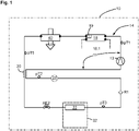
1 ein schematisches und vereinfachtes Schaltbild einer Kälteanlage für ein Kraftfahrzeug; -
2 ein schematisches und vereinfachtes Schaltbild einer weiteren Kälteanlage für ein Kraftfahrzeug; -
3 ein schematisches und vereinfachtes Schaltbild einer weiteren Kälteanlage für ein Kraftfahrzeug; -
4 ein schematisches und vereinfachtes Schaltbild einer weiteren Kälteanlage für ein Kraftfahrzeug; -
5 ein schematisches und vereinfachtes Schaltbild einer weiteren Kälteanlage für ein Kraftfahrzeug; -
6 eine schematische und vereinfachte Darstellung eines Kraftfahrzeugs.
-
1 a schematic and simplified circuit diagram of a refrigeration system for a motor vehicle; -
2 a schematic and simplified circuit diagram of another refrigeration system for a motor vehicle; -
3 a schematic and simplified circuit diagram of another refrigeration system for a motor vehicle; -
4 a schematic and simplified circuit diagram of another refrigeration system for a motor vehicle; -
5 a schematic and simplified circuit diagram of another refrigeration system for a motor vehicle; -
6 a schematic and simplified representation of a motor vehicle.
In
Der erste Wärmeübertrager 18 ist mit einem hier angedeuteten Kühlmittelkreislauf 18.1 verbunden. Im ersten Wärmeübertrager erfolgt somit eine Wärmeabgabe von dem erhitzten und unter Hochdruck stehenden Kältemittel an das Kühlmittel im Kühlmittelkreislauf 18.1. Das Kühlmittel im Kühlmittelkreislauf 18.1 kann seinerseits mittels eines beispielsweise mit Luft beaufschlagten Kühlers, der hier nicht dargestellt ist, gekühlt werden.The
Der erste Wärmeübertrager 18 kann mit einem hier als Rechteck illustrierten hochdruckseitigen Kältemittelspeicher 19, auch als Sammler bezeichnet, ausgeführt sein. Der Sammler 19 ist ausgangsseitig am ersten Wärmeübertrager 18 im Kältemittelkreis 11 vorgesehen. Alternativ kann ein niederdruckseitiger Kältemittelsammler 24 (Niederdruck-Akkumulator) vorgesehen sein, der gestrichelt dargestellt ist.The
Stromabwärts von dem ersten Wärmeübertrager 18, der als Gaskühler bzw. Kondensator (Verflüssiger) wirkt bzw. eingesetzt wird, ist ein zweiter Wärmeübertrager 40 angeordnet. Der zweite Wärmeübertrager 40 dient dazu bzw. ist dazu eingerichtet, eine zusätzliche Aus-/ Abkühlung bzw. Unterkühlung des Kältemittels zu bewirken. Im Beispiel der
Der Verdampfer 22 ist in allen Beispielen der
Die Kälteanlage kann optional einen inneren Wärmeübertrager 20 aufweisen, der in den
Der zweite Wärmeübertrager kann in einer Kälteanlage 10 gemäß
Der Bypassabschnitt 42 kann beispielweise stromaufwärts von dem zweiten Wärmeübertrager 40 abzweigen, etwa an einem Abzweig Ab4. Der Bypassabschnitt 42 kann bei einem Abzweig Ab9 wieder in den Kältemittelkreislauf 11 münden bzw. mit diesem verbunden sein. Der Abzweig Ab9 ist dabei stromabwärts von dem zweiten Wärmeübertrager 40 bzw. 40a angeordnet.The bypass section 42 can, for example, branch off upstream of the
Zwischen dem Abzweig Ab4 und dem zweiten Wärmeübertrager 40 kann eine Ventileinrichtung, insbesondere ein Absperrventil A6 angeordnet sein. Im Bypassabschnitt 42 kann stromabwärts von dem Abzweig Ab4 eine Bypassventileinrichtung, insbesondere ein Bypassabsperrventil A7, angeordnet sein. Mittels der Absperrventile A6, A7 kann der Kältemittelfluss durch den zweiten Wärmeübertrager 40, 40a bzw. den Bypassabschnitt 42 ermöglicht oder verhindert werden oder (allgemeiner gesprochen) wahlweise eingestellt werden. Um eine Rückströmen von Kältemittel in den zweiten Wärmeübertrager 40, 40a zu verhindern kann stromabwärts von diesem und stromaufwärts von dem Abzweig Ab9 ein weiteres Absperrventil, hier als Rückschlagventil R6 ausgeführt, angeordnet sein. Die Absperrventile A6 und A7 können auch zu einem Kombinationsventil, beispielsweise einem 3-2-Wegeventil zusammengeführt werden.A valve device, in particular a shut-off valve A6, can be arranged between the branch Ab4 and the
In einer weiteren Ausgestaltung können die Ventileinrichtungen A6 und A7 als stufenlosverstellbares Ventil ausgeführt sein. Hierdurch können neben der Funktionsabbildung vollständiges Sperren bzw. Durchströmen auch beliebige Zwischenstellungen ermöglicht werden, die ihrerseits für ein erweitertes Wärmemanagement innerhalb der Prozessführung eingesetzt werden können. Dabei wird ein gleichzeitiges Durchströmen beider Kältemittelstränge ermöglicht mit verschiedenen Kältemittelverteilungen. Der zweite Wärmeübertrager 40 kann dabei luftseitig mit einem (stufenlos) verschließbaren bzw. verstellbaren Kühllufteintritt 41 versehen sein, der seinerseits speziell bei niedrigeren Umgebungstemperaturen die Kältemittelverteilung positiv beeinflussen kann. Eine Kombination der stufenlos verstellbaren Ventile A6 und A7 entspräche in diesem Fall beispielsweise einem Drehschieberkonzept.In a further embodiment, the valve devices A6 and A7 can be designed as a continuously adjustable valve. In this way, in addition to the functional representation of complete blocking or flow, any intermediate positions can also be made possible, which in turn can be used for extended heat management within the process control. Simultaneous flow through both refrigerant lines is made possible with different refrigerant distributions. The
In einem Wärmepumpenbetrieb der Kälteanlage 10 kann das Kältemittel ausgehend vom Kältemittelverdichter 12 durch den ersten indirekt wirkenden Wärmeübertrager 18 strömen. Danach wird das Kältemittel bei geöffnetem Bypassabsperrventil A7 und geschlossenem Absperrventil A6 durch den Bypassabschnitt 42 geleitet. Von dem Bypassabschnitt 42 gelangt das Kältemittel im Kältemittelkreislauf 11 zu einem Abzweig Ab1. Danach strömt das Kältemittel je nach Einstellung von zugeordneten Expansionsventilen AE1 bzw. AE2 vollständig oder als Teilmassenstrom in den dritten Wärmeübertrager bzw. Chiller 28 oder/und den Verdampfer 22. Der dritte Wärmeübertrager bzw. Chiller kann dabei als Wasserwärmepumpen-Verdampfer eingesetzt werden, um über den Kühlmittelkreis 28.2 Wärme aus den Hochvoltkomponenten, insbesondere der E-Maschine aufzunehmen, die für die Erwärmung des Kabinenzuluftstroms eingesetzt wird. Wenn beispielsweise das Kühlmittel im Kühlmittelkreislauf erwärmt werden soll, um die Hochvoltbatterie auf eine optimale Betriebstemperatur zu bringen, etwa bei bzw. kurz nach einem Systemstart der Kälteanlage 10 beim Start des Fahrzeugs oder bei geringen Außentemperaturen, beispielsweise kleiner als 5°C, kann so die über den Verdichter 12 erzeugte Wärme, ohne vorhergehende Abgabe am ersten Wärmeübertrager 18 direkt zu dem Chiller 28 gefördert werden. Je nachdem, ob der Batterieheizprozess über einen rechts- oder linksläufigen Dreiecksprozess erfolgt ist dem Chiller 28 noch ein weiteres Expansionsorgan im Bedarfsfall nachzuschalten, insbesondere zwischen dem Chiller 28 und dem Abzweig Ab2.When the
Weiterhin kann ein Dreiecksprozess mit stehendem Wasser im Chiller 28 abgebildet werden, so dass nur die in Wärme umgewandelte Antriebsleistung des Verdichters 12 an den ersten Wärmeübertrager abgegeben wird, der seinerseits über eine nicht weiter dargestellte systemseitige Verschaltung mit einem Innenraumwärmeübertrager, seinerseits innerhalb des Klimagerätes 32 positioniert, zur Erwärmung des Kabinenzuluftstroms verbunden ist.Furthermore, a triangular process with standing water in the
Es wird allgemein darauf hingewiesen, dass bei einem indirekten Wärmeübertrager 40a unterschiedliche Kühlmittel eingesetzt werden können, wie beispielsweise ein Wasser-Glykol-Gemisch, ein Öl oder eine sonstige als Kühlmittel geeignete Flüssigkeit bzw. Flüssigkeitszusammensetzung.It is generally pointed out that in the case of an
Im Rahmen der Beschreibung der
Die Kälteanlage 10 umfasst weiter ein Heizregister 26 (auch als Heizkondensator oder Heizgaskühler bezeichnet). Stromaufwärts des Heizregisters 26 ist ein Absperrventil A3 angeordnet. Stromabwärts des Heizregisters 26 ist ein Absperrventil A1 angeordnet. Ferner ist stromabwärts des Heizregisters 26 ein Expansionsventil AE4 angeordnet.The
Im Rahmen der Beschreibung der
Die Kälteanlage 10 der
Im AC-Betrieb des Kältemittelkreislaufs 11 strömt das auf Hochdruck verdichtete Kältemittel ausgehend von dem Kältemittelverdichter 12 bei offenem Absperrventil A4 in den äußeren Wärmeübertrager 18. Von dort strömt es zu dem zweiten Wärmeübertrager 40/ 40a zur weiteren Abkühlung bzw. Unterkühlung des Kältemittels, dem sich stromabwärts anschließenden Hochdruckabschnitt des inneren Wärmeübertragers 20 und dem vollständig geöffneten Expansionsventil AE3. Über einen Abzweigpunkt Ab1 kann das Kältemittel zum Expansionsventil AE2 und in den Innenraum-Verdampfer 22 strömen (Verdampferabschnitt 22.1). Parallel oder alternativ kann das Kältemittel über einen Abzweigpunkt Ab4 und das Expansionsventil AE1 in den Chiller 28 strömen (Chillerabschnitt 28.1). Aus dem Verdampfer 22 oder/und dem Chiller 28 strömt das Kältemittel niederdruckseitig in den Sammler 24 und durch den Niederdruckabschnitt des inneren Wärmeübertragers 20 zurück zum Verdichter 12. Für das Beispiel der Kälteanlage 10 der
In dem AC-Betrieb ist der Heizzweig 16.1 bzw. der Sekundärstrang 16 mittels des Absperrventils A3 abgesperrt, so dass heißes Kältemittel nicht durch das Heizregister 26 strömen kann. Zur Rückholung von Kältemittel aus dem inaktiven Heizzweig 16.1 kann das als Absperrventil ausgebildete Absperrorgan A5 geöffnet werden, so dass das Kältemittel über das Absperrorgan A5 und das Rückschlagventil R2, bei gleichzeitig geschlossenem Absperrorgan A2, in Richtung des Sammlers 24 strömen kann.In AC operation, the heating branch 16.1 or the
Im AC-Betrieb wird der zweite Wärmeübertrager 40, 40a als Ab-/ Auskühl- bzw. Unterkühlungsstrecke von Kältemittel durchströmt, wie dies bereits oben für die Beispiele der
Im Heizbetrieb des Kältemittelkreislaufs 11 wird das Absperrventil A4 geschlossen und das Absperrventil A3 geöffnet, so dass heißes Kältemittel in den Heizzweig 16.1 strömen kann.In the heating mode of the
Zur Durchführung der Heizfunktion mittels des Chillers 28 zur Realisierung eines Wasser-Wärmepumpenbetriebs strömt das mittels des Kältemittelverdichters 12 verdichtete Kältemittel über das geöffnete Absperrventil A3 in das Heizregister 26 . Am Heizregister 26 wird Wärme an einen in den Fahrzeuginnenraum geführten Zuluftstrom L abgegeben. Das Kältemittel strömt anschließend über das geöffnete Absperrventil A1 und den Abzweigpunkt Ab1. Es wird mittels des Expansionsventils AE1 in den Chiller 28 zur Aufnahme von Abwärme der in einem Kühlmittelkreislauf 28.2 angeordneten elektrischen und/oder elektronischen Komponenten entspannt. Bei dieser Heizfunktion sind die Expansionsventile AE3 und AE4 geschlossen, das Absperrventil A5 geschlossen und das Absperrventil A2 geöffnet. Dabei kann über das Absperrventil A2 im Wasser-Wärmepumpenbetrieb ausgelagertes Kältemittel aus einem Bidirektionalzweig 14.1 bzw. dem Primärstrang 14 abgesaugt und über das Rückschlagventil R2 dem Sammler 24 zugeführt werden.In order to carry out the heating function by means of the
Zur Durchführung der Heizfunktion für den Innenraum des Kraftfahrzeugs mittels des ersten (äußeren) Wärmeübertragers 18 als Wärmepumpenverdampfer strömt das mittels des Kältemittelverdichters 12 verdichtete Kältemittel über das geöffnete Absperrventil A3 zur Abgabe von Wärme an einen Zuluftstrom L in das Heizregister 26. Anschließend wird es über das geöffnete Absperrventil A1 mittels des Expansionsventils AE3 in den äußeren Wärmeübertrager 18 zur Aufnahme von Wärme aus der Umgebungsluft entspannt. Danach strömt das Kältemittel über einen Wärmepumpenrückführzweig 15 zum Sammler 24 und zurück zum Kältemittelverdichter 12. Die Expansionsventile AE1, AE2 und AE4 bleiben dabei, ebenso wie das Absperrventil A5, geschlossen.To carry out the heating function for the interior of the motor vehicle by means of the first (outer)
Wie sich aus der Darstellung der
Wird das Rückschlagventil R6 gegen ein nicht dargestelltes Absperrventil getauscht, kann der zweite Wärmeübertrage 28 auch in einem Wärmepumpenbetrieb bei entgegengesetzter Durchströmung zum AC-Betrieb eingebunden werden und dabei direkt Wärme aus der Umgebungsluft aufnehmen. Ansonsten erfolgt bzw. kann wie beschrieben eine Wärmeaufnahme über den ersten Wärmeübertrager 18 indirekt über die Umgebungsluft bzw. über weitere in den Kühlmittelkreis 18.1 wärmeeinbringende Komponenten erfolgen.If the check valve R6 is exchanged for a shut-off valve (not shown), the
Eine indirekte Dreiecksschaltung kann dadurch realisiert werden, dass bei geöffnetem Absperrventil A1 das von dem Kältemittelverdichter 12 verdichtete Kältemittel mittels des Expansionsventils AE1 in den Chiller 28 entspannt wird, wobei gleichzeitig kühlmittelseitig, also in dem Kühlmittelkreislauf 28.2 kein Massenstrom erzeugt wird, also bspw. das als Kühlmittel verwendete Fluid, wie etwa Wasser oder Wasser-Glykol-Gemisch, auf der Kühlmittelseite des Chillers 28 stehen bleibt bzw. der Chiller 28 nicht aktiv von Kühlmittel durchströmt wird. Die Expansionsventile AE2, AE3 und AE4 bleiben bei dieser Schaltvariante geschlossen.An indirect delta connection can be implemented in that, when the shut-off valve A1 is open, the refrigerant compressed by the
Bei einem Nachheiz- bzw.- Reheat-Betrieb wird der in den Fahrzeuginnenraum zugeführte Zuluftstrom L mittels des Verdampfers 22 zunächst gekühlt und damit entfeuchtet. Mit der auf das Kältemittel durch Verdampfung und Entfeuchtung übertragenen Wärme sowie der dem Kältemittel über den Verdichter 12 zugeführten Wärme kann der Zuluftstrom L mittels des Heizregisters 26 vollständig oder zumindest teilweise wieder erwärmt werden.In an after-heating or reheat operation, the supply air flow L fed into the vehicle interior is first cooled by means of the
Hierzu weist die Kälteanlage 10, insbesondere das Klimagerät 32, zwischen dem Verdampfer 22 und dem Heizregister 26 einstellbare, insbesondere steuerbare und schwenkbare, Temperaturklappen auf, die hier aber nicht weiter dargestellt sind.For this purpose, the
Es wird darauf hingewiesen, dass in den
Die hier in verschiedenen Beispielen vorgestellte Kälteanlage mit einem ersten (äußeren), indirekt wirkenden Wärmeübertrager 18 weist zur Steigerung der Effizienz des Kälteanlagenbetriebs, insbesondere in einem Kühlbetrieb (AC-Betrieb), den zweiten Wärmeübertrager 40, 40a zur weiteren Aus-/ Abkühlung bzw. Unterkühlung von Kältemittel auf. Optional kann für eine Kälteanlage 10 mit Wärmepumpenfunktion (
Wie sich aus den verschiedenen Beispielen ergibt, ist die Umsetzung bzw. Einbindung von wenigsten einem zweiten Wärmeübertrager 40, 40a generell für alle Kältemittel bzw. alle Kältekreisvarianten denkbar. Die beschriebene Struktur der Kältanlagen 10 kann sowohl für unterkritisch als auch für überkritisch arbeitende Kältemittel bzw. Prozesse angewandt werden. Weiter ist es, wie oben beschrieben, einerseits möglich diesen Aufbau für Systeme mit einem hochdruckseitig angeordneten Kältemittelspeicher 19 umzusetzen und damit eine reale Unterkühlung des im System zirkulierenden Kältemittels zu erwirken. Andererseits können aber auch Systeme mit niederdruckseitig angeordneten Kältemittelspeichern 24 von einem nachgelagerten Wärmeübertrager 40, 40a profitieren, der letztlich ein weitere Auskühlung des Kältemittels ermöglicht und damit den Gesamtprozess effizienter arbeiten lässt.As can be seen from the various examples, the implementation or integration of at least one
ZITATE ENTHALTEN IN DER BESCHREIBUNGQUOTES INCLUDED IN DESCRIPTION
Diese Liste der vom Anmelder aufgeführten Dokumente wurde automatisiert erzeugt und ist ausschließlich zur besseren Information des Lesers aufgenommen. Die Liste ist nicht Bestandteil der deutschen Patent- bzw. Gebrauchsmusteranmeldung. Das DPMA übernimmt keinerlei Haftung für etwaige Fehler oder Auslassungen.This list of documents cited by the applicant was generated automatically and is included solely for the better information of the reader. The list is not part of the German patent or utility model application. The DPMA assumes no liability for any errors or omissions.
Zitierte PatentliteraturPatent Literature Cited
- DE 102012212227 A1 [0002]DE 102012212227 A1 [0002]
- DE 102017212309 B3 [0003]DE 102017212309 B3 [0003]
Claims (12)
Priority Applications (1)
| Application Number | Priority Date | Filing Date | Title |
|---|---|---|---|
| DE102020130196.0A DE102020130196A1 (en) | 2020-11-16 | 2020-11-16 | Refrigeration system for a motor vehicle with an additional heat exchanger as an undercooling section, motor vehicle with such a refrigeration system |
Applications Claiming Priority (1)
| Application Number | Priority Date | Filing Date | Title |
|---|---|---|---|
| DE102020130196.0A DE102020130196A1 (en) | 2020-11-16 | 2020-11-16 | Refrigeration system for a motor vehicle with an additional heat exchanger as an undercooling section, motor vehicle with such a refrigeration system |
Publications (1)
| Publication Number | Publication Date |
|---|---|
| DE102020130196A1 true DE102020130196A1 (en) | 2022-05-19 |
Family
ID=81345351
Family Applications (1)
| Application Number | Title | Priority Date | Filing Date |
|---|---|---|---|
| DE102020130196.0A Pending DE102020130196A1 (en) | 2020-11-16 | 2020-11-16 | Refrigeration system for a motor vehicle with an additional heat exchanger as an undercooling section, motor vehicle with such a refrigeration system |
Country Status (1)
| Country | Link |
|---|---|
| DE (1) | DE102020130196A1 (en) |
Cited By (6)
| Publication number | Priority date | Publication date | Assignee | Title |
|---|---|---|---|---|
| WO2024120855A1 (en) * | 2022-12-05 | 2024-06-13 | Audi Ag | Cooling unit having a heat pump function and a bypass section flowed through in heat pump operation, and motor vehicle having such a cooling unit |
| US20250058603A1 (en) * | 2023-08-17 | 2025-02-20 | Hyundai Motor Company | Heat pump system for a vehicle |
| WO2026008317A1 (en) * | 2024-07-05 | 2026-01-08 | Valeo Systemes Thermiques | Thermal conditioning system for a motor vehicle |
| WO2026008261A1 (en) * | 2024-07-05 | 2026-01-08 | Valeo Systemes Thermiques | Thermal conditioning system for a motor vehicle |
| FR3164145A1 (en) * | 2024-07-05 | 2026-01-09 | Valeo Systemes Thermiques | Automotive Vehicle Thermal Conditioning System |
| US12545080B2 (en) * | 2023-08-17 | 2026-02-10 | Hyundai Motor Company | Heat pump system for a vehicle |
Citations (5)
| Publication number | Priority date | Publication date | Assignee | Title |
|---|---|---|---|---|
| US5092138A (en) | 1990-07-10 | 1992-03-03 | The University Of Maryland | Refrigeration system |
| US5235820A (en) | 1991-11-19 | 1993-08-17 | The University Of Maryland | Refrigerator system for two-compartment cooling |
| WO2008037896A2 (en) | 2006-09-28 | 2008-04-03 | Heliotrans | Module usable for heat storage and transfer |
| DE102012212227A1 (en) | 2012-07-12 | 2014-01-16 | Behr Gmbh & Co. Kg | Cooling system, particularly vehicle air conditioning system, has heat transmission device with one or multiple thermoelectric elements, particularly Peltier elements, which are connected with subcooling path |
| DE102017212309B3 (en) | 2017-07-19 | 2018-09-06 | Bayerische Motoren Werke Aktiengesellschaft | Coolant circuit with at least two cooling circuits and a latent heat storage |
-
2020
- 2020-11-16 DE DE102020130196.0A patent/DE102020130196A1/en active Pending
Patent Citations (5)
| Publication number | Priority date | Publication date | Assignee | Title |
|---|---|---|---|---|
| US5092138A (en) | 1990-07-10 | 1992-03-03 | The University Of Maryland | Refrigeration system |
| US5235820A (en) | 1991-11-19 | 1993-08-17 | The University Of Maryland | Refrigerator system for two-compartment cooling |
| WO2008037896A2 (en) | 2006-09-28 | 2008-04-03 | Heliotrans | Module usable for heat storage and transfer |
| DE102012212227A1 (en) | 2012-07-12 | 2014-01-16 | Behr Gmbh & Co. Kg | Cooling system, particularly vehicle air conditioning system, has heat transmission device with one or multiple thermoelectric elements, particularly Peltier elements, which are connected with subcooling path |
| DE102017212309B3 (en) | 2017-07-19 | 2018-09-06 | Bayerische Motoren Werke Aktiengesellschaft | Coolant circuit with at least two cooling circuits and a latent heat storage |
Cited By (8)
| Publication number | Priority date | Publication date | Assignee | Title |
|---|---|---|---|---|
| WO2024120855A1 (en) * | 2022-12-05 | 2024-06-13 | Audi Ag | Cooling unit having a heat pump function and a bypass section flowed through in heat pump operation, and motor vehicle having such a cooling unit |
| US20250058603A1 (en) * | 2023-08-17 | 2025-02-20 | Hyundai Motor Company | Heat pump system for a vehicle |
| US12545080B2 (en) * | 2023-08-17 | 2026-02-10 | Hyundai Motor Company | Heat pump system for a vehicle |
| WO2026008317A1 (en) * | 2024-07-05 | 2026-01-08 | Valeo Systemes Thermiques | Thermal conditioning system for a motor vehicle |
| WO2026008261A1 (en) * | 2024-07-05 | 2026-01-08 | Valeo Systemes Thermiques | Thermal conditioning system for a motor vehicle |
| FR3164144A1 (en) * | 2024-07-05 | 2026-01-09 | Valeo Systemes Thermiques | Automotive Vehicle Thermal Conditioning System |
| FR3164147A1 (en) * | 2024-07-05 | 2026-01-09 | Valeo Systemes Thermiques | Automotive Vehicle Thermal Conditioning System |
| FR3164145A1 (en) * | 2024-07-05 | 2026-01-09 | Valeo Systemes Thermiques | Automotive Vehicle Thermal Conditioning System |
Similar Documents
| Publication | Publication Date | Title |
|---|---|---|
| EP3697635B1 (en) | Method for operating a coolant circuit and vehicle air-conditioning system | |
| DE102020111511B4 (en) | Refrigeration system and heat pump arrangement for battery-powered vehicles and method for operating a refrigeration system and heat pump arrangement | |
| DE102020117471B4 (en) | Heat pump arrangement with indirect battery heating for battery-operated motor vehicles and method for operating a heat pump arrangement | |
| DE102011118162B4 (en) | Combined refrigeration system and heat pump and method for operating the system with function-dependent refrigerant transfer within the refrigerant circuit | |
| DE102015218824B4 (en) | Heat pump system and method for operating such a system | |
| DE102015122721B4 (en) | Air conditioning system of a motor vehicle and method for operating the air conditioning system | |
| EP3444542B1 (en) | Circulation system for a vehicle and method for same | |
| DE102010042127B4 (en) | Refrigerant circuit of an air conditioning system of a motor vehicle | |
| DE102020130196A1 (en) | Refrigeration system for a motor vehicle with an additional heat exchanger as an undercooling section, motor vehicle with such a refrigeration system | |
| DE102020111505B4 (en) | Heat pump arrangement for battery-operated vehicles and method for operating a heat pump arrangement | |
| DE102019107191A1 (en) | Heating system for an electric or hybrid vehicle, electric or hybrid vehicle, method for operating a heating system | |
| EP3595919B1 (en) | Cooling system of a vehicle, comprising a coolant circuit which can be operated as a cooling circuit for an ac operation and as a heat pump circuit for a heating operation | |
| DE102018201945B4 (en) | Method for operating a refrigerant circuit and vehicle refrigeration system | |
| DE112021003804T5 (en) | STEAM INJECTION MODULE AND HEAT PUMP SYSTEM WITH THIS MODULE | |
| DE102018207049B4 (en) | Refrigeration system for a vehicle with a refrigerant circuit having a heat pump function | |
| DE102020119813B4 (en) | Refrigerant circuit of a combined refrigeration and heat pump system with integrated steam injection circuit | |
| DE102019203292B4 (en) | Method for operating a refrigeration system for a vehicle with a refrigerant circuit having a heat pump function | |
| DE102012022564A1 (en) | Air conditioning device for motor vehicle, comprises mechanically driven compressor and electrically driven compressor, which are fluidically connected in series, where each compressor is individually bypassed by assigned bypass line | |
| DE102016004999B3 (en) | Vehicle air conditioning | |
| DE102016203045A1 (en) | Tempering device for tempering an interior of a vehicle and method for operating such a tempering device | |
| DE102019203295A1 (en) | Method for operating a refrigeration system for a vehicle with a refrigerant circuit having a heat pump function | |
| WO2023280507A1 (en) | Refrigeration circuit, and heat management system and motor vehicle having a refrigeration circuit of this type | |
| WO2024120855A1 (en) | Cooling unit having a heat pump function and a bypass section flowed through in heat pump operation, and motor vehicle having such a cooling unit | |
| DE102018211568B4 (en) | Refrigeration system with a cooled oil circuit for a motor vehicle, motor vehicle with such a refrigeration system | |
| DE102021200937A1 (en) | Air conditioning system for a motor vehicle |
Legal Events
| Date | Code | Title | Description |
|---|---|---|---|
| R012 | Request for examination validly filed | ||
| R016 | Response to examination communication |