DE102020119229A1 - Head clamp with two-piece C-arm - Google Patents
Head clamp with two-piece C-arm Download PDFInfo
- Publication number
- DE102020119229A1 DE102020119229A1 DE102020119229.0A DE102020119229A DE102020119229A1 DE 102020119229 A1 DE102020119229 A1 DE 102020119229A1 DE 102020119229 A DE102020119229 A DE 102020119229A DE 102020119229 A1 DE102020119229 A1 DE 102020119229A1
- Authority
- DE
- Germany
- Prior art keywords
- arm
- head
- partial
- head clamp
- fixing element
- Prior art date
- Legal status (The legal status is an assumption and is not a legal conclusion. Google has not performed a legal analysis and makes no representation as to the accuracy of the status listed.)
- Withdrawn
Links
- 210000003625 skull Anatomy 0.000 claims abstract description 24
- 238000006073 displacement reaction Methods 0.000 claims abstract description 10
- 230000008878 coupling Effects 0.000 claims description 6
- 238000010168 coupling process Methods 0.000 claims description 6
- 238000005859 coupling reaction Methods 0.000 claims description 6
- 238000000034 method Methods 0.000 claims description 5
- 230000008901 benefit Effects 0.000 description 5
- 208000003443 Unconsciousness Diseases 0.000 description 1
- 230000000295 complement effect Effects 0.000 description 1
- 230000000368 destabilizing effect Effects 0.000 description 1
- 238000011161 development Methods 0.000 description 1
- 230000018109 developmental process Effects 0.000 description 1
- 230000000694 effects Effects 0.000 description 1
- 210000003746 feather Anatomy 0.000 description 1
- 238000003384 imaging method Methods 0.000 description 1
- 238000005259 measurement Methods 0.000 description 1
Images


Classifications
-
- A—HUMAN NECESSITIES
- A61—MEDICAL OR VETERINARY SCIENCE; HYGIENE
- A61B—DIAGNOSIS; SURGERY; IDENTIFICATION
- A61B5/00—Measuring for diagnostic purposes; Identification of persons
- A61B5/70—Means for positioning the patient in relation to the detecting, measuring or recording means
- A61B5/702—Posture restraints
-
- A—HUMAN NECESSITIES
- A61—MEDICAL OR VETERINARY SCIENCE; HYGIENE
- A61B—DIAGNOSIS; SURGERY; IDENTIFICATION
- A61B5/00—Measuring for diagnostic purposes; Identification of persons
- A61B5/05—Detecting, measuring or recording for diagnosis by means of electric currents or magnetic fields; Measuring using microwaves or radio waves
- A61B5/055—Detecting, measuring or recording for diagnosis by means of electric currents or magnetic fields; Measuring using microwaves or radio waves involving electronic [EMR] or nuclear [NMR] magnetic resonance, e.g. magnetic resonance imaging
-
- A—HUMAN NECESSITIES
- A61—MEDICAL OR VETERINARY SCIENCE; HYGIENE
- A61B—DIAGNOSIS; SURGERY; IDENTIFICATION
- A61B6/00—Apparatus or devices for radiation diagnosis; Apparatus or devices for radiation diagnosis combined with radiation therapy equipment
- A61B6/02—Arrangements for diagnosis sequentially in different planes; Stereoscopic radiation diagnosis
- A61B6/03—Computed tomography [CT]
- A61B6/032—Transmission computed tomography [CT]
-
- A—HUMAN NECESSITIES
- A61—MEDICAL OR VETERINARY SCIENCE; HYGIENE
- A61B—DIAGNOSIS; SURGERY; IDENTIFICATION
- A61B6/00—Apparatus or devices for radiation diagnosis; Apparatus or devices for radiation diagnosis combined with radiation therapy equipment
- A61B6/04—Positioning of patients; Tiltable beds or the like
- A61B6/0407—Supports, e.g. tables or beds, for the body or parts of the body
- A61B6/0421—Supports, e.g. tables or beds, for the body or parts of the body with immobilising means
-
- A—HUMAN NECESSITIES
- A61—MEDICAL OR VETERINARY SCIENCE; HYGIENE
- A61B—DIAGNOSIS; SURGERY; IDENTIFICATION
- A61B6/00—Apparatus or devices for radiation diagnosis; Apparatus or devices for radiation diagnosis combined with radiation therapy equipment
- A61B6/50—Apparatus or devices for radiation diagnosis; Apparatus or devices for radiation diagnosis combined with radiation therapy equipment specially adapted for specific body parts; specially adapted for specific clinical applications
- A61B6/501—Apparatus or devices for radiation diagnosis; Apparatus or devices for radiation diagnosis combined with radiation therapy equipment specially adapted for specific body parts; specially adapted for specific clinical applications for diagnosis of the head, e.g. neuroimaging or craniography
-
- A—HUMAN NECESSITIES
- A61—MEDICAL OR VETERINARY SCIENCE; HYGIENE
- A61B—DIAGNOSIS; SURGERY; IDENTIFICATION
- A61B90/00—Instruments, implements or accessories specially adapted for surgery or diagnosis and not covered by any of the groups A61B1/00 - A61B50/00, e.g. for luxation treatment or for protecting wound edges
- A61B90/10—Instruments, implements or accessories specially adapted for surgery or diagnosis and not covered by any of the groups A61B1/00 - A61B50/00, e.g. for luxation treatment or for protecting wound edges for stereotaxic surgery, e.g. frame-based stereotaxis
- A61B90/14—Fixators for body parts, e.g. skull clamps; Constructional details of fixators, e.g. pins
-
- A—HUMAN NECESSITIES
- A61—MEDICAL OR VETERINARY SCIENCE; HYGIENE
- A61B—DIAGNOSIS; SURGERY; IDENTIFICATION
- A61B90/00—Instruments, implements or accessories specially adapted for surgery or diagnosis and not covered by any of the groups A61B1/00 - A61B50/00, e.g. for luxation treatment or for protecting wound edges
- A61B90/36—Image-producing devices or illumination devices not otherwise provided for
- A61B90/37—Surgical systems with images on a monitor during operation
- A61B2090/374—NMR or MRI
-
- A—HUMAN NECESSITIES
- A61—MEDICAL OR VETERINARY SCIENCE; HYGIENE
- A61B—DIAGNOSIS; SURGERY; IDENTIFICATION
- A61B90/00—Instruments, implements or accessories specially adapted for surgery or diagnosis and not covered by any of the groups A61B1/00 - A61B50/00, e.g. for luxation treatment or for protecting wound edges
- A61B90/36—Image-producing devices or illumination devices not otherwise provided for
- A61B90/37—Surgical systems with images on a monitor during operation
- A61B2090/376—Surgical systems with images on a monitor during operation using X-rays, e.g. fluoroscopy
- A61B2090/3762—Surgical systems with images on a monitor during operation using X-rays, e.g. fluoroscopy using computed tomography systems [CT]
-
- A—HUMAN NECESSITIES
- A61—MEDICAL OR VETERINARY SCIENCE; HYGIENE
- A61B—DIAGNOSIS; SURGERY; IDENTIFICATION
- A61B5/00—Measuring for diagnostic purposes; Identification of persons
- A61B5/68—Arrangements of detecting, measuring or recording means, e.g. sensors, in relation to patient
- A61B5/6801—Arrangements of detecting, measuring or recording means, e.g. sensors, in relation to patient specially adapted to be attached to or worn on the body surface
- A61B5/6813—Specially adapted to be attached to a specific body part
- A61B5/6814—Head
Landscapes
- Health & Medical Sciences (AREA)
- Life Sciences & Earth Sciences (AREA)
- Engineering & Computer Science (AREA)
- Medical Informatics (AREA)
- Surgery (AREA)
- General Health & Medical Sciences (AREA)
- Heart & Thoracic Surgery (AREA)
- Veterinary Medicine (AREA)
- Public Health (AREA)
- Physics & Mathematics (AREA)
- Animal Behavior & Ethology (AREA)
- Nuclear Medicine, Radiotherapy & Molecular Imaging (AREA)
- Biomedical Technology (AREA)
- Pathology (AREA)
- Molecular Biology (AREA)
- Biophysics (AREA)
- Radiology & Medical Imaging (AREA)
- High Energy & Nuclear Physics (AREA)
- Optics & Photonics (AREA)
- Oral & Maxillofacial Surgery (AREA)
- Neurosurgery (AREA)
- Neurology (AREA)
- Dentistry (AREA)
- Pulmonology (AREA)
- Theoretical Computer Science (AREA)
- Physical Education & Sports Medicine (AREA)
- Magnetic Resonance Imaging Apparatus (AREA)
Abstract
Die Erfindung betrifft eine Kopfklemme zur sicheren Fixierung eines Kopfes eines Patienten während einer Untersuchung in einem CT- oder MRT-Gerät, umfassend einen C-Bogen (2) mit einem ersten Ende (2a1) und einem gegenüberliegenden zweiten Ende (2b1), ein in einer Aufnahme in dem ersten Ende (2a1) des C-Bogens (2) befestigten, entlang einer ersten radial orientierten Verschiebeachse verschieblichen ersten Fixierelement (3a), und ein in einer Aufnahme in dem zweiten Ende (2b1) des C-Bogens entlang einer zweiten radialen Achse orientierten zweiten Fixierelement (3b), welches eine Wippe (3b1) mit zwei Schädeldornen (3b2, 3b3), wobei die Wippe (3b1) um eine senkrecht auf einer durch den C-Bogen definierte Ebene stehende erste Schwenkachse (A1) verschwenkbar gelagert ist, wobei der C-Bogen (2) in einen ersten Teilbogen (2a) und einen zweiten Teilbogen (2b) untergliedert ist, wobei der erste Teilbogen (2a) und der zweite Teilbogen (2b) über ein zumindest in einer geschlossenen Stellung fixierbares Gelenk (23) verbunden sind, sodass die Teilbögen um eine zweite senkrechte auf der C-Bogen Ebene stehenden Schwenkachse (A2) verschwenkbar sind.
Description
Vorliegende Erfindung betrifft eine Kopfklemme zur sicheren Fixierung eines Kopfes eines Patienten während einer Untersuchung in einem CT- oder MRT-Gerät sowie eine Verwendung einer solchen Kopfklemme.The present invention relates to a head clamp for securely fixing a patient's head during an examination in a CT or MRT device and to the use of such a head clamp.
Bei der Untersuchung von Patienten in CT- oder MRT-Geräten ist stets sicherzustellen, dass der Patient sich während der Erstellung der Aufnahmen nicht bewegt. Dies gilt sowohl für die Zeit zwischen zwei aufeinanderfolgenden 2D-Schnittbildern als auch während der Aufnahme eines einzelnen Schnittbildes, welche immer eine gewisse Zeit in Anspruch nimmt. Eine Bewegung während oder zwischen der Erstellung der 2D-Schnittbilder würde die Unsicherheit im Messprozess erhöhen und somit die effektive Bildauflösung verringern.When examining patients in CT or MRI machines, it must always be ensured that the patient does not move while the images are being taken. This applies both to the time between two consecutive 2D sectional images and to the recording of a single sectional image, which always takes a certain amount of time. A movement during or between the creation of the 2D sectional images would increase the uncertainty in the measurement process and thus reduce the effective image resolution.
Um bei Untersuchungen des Kopfes eine bewusste oder unbewusste Bewegung des Kopfs durch den Patienten zu unterbinden sind Vorrichtungen bekannt, mittels derer der Kopf des Patienten fixiert werden kann. Diese sogenannten Kopfklemmen bestehen üblicherweise aus einem C-förmigen Bogen, der den Kopf des Patienten von unten umgreift und an dessen gegenüberliegenden Enden Fixierelemente mit Schädeldornen befestigt sind. Die zwei gegenüberliegenden Fixierelemente bilden gemeinsam eine sogenannte Zweipunkt-Fixierung, wobei eines der Befestigungselemente einen einzelnen Schädeldorn trägt, der entlang einer radial orientierten Verschieberichtung auf den Kopf des Patienten zu beweglich ist. Das gegenüberliegende zweite Fixierelement trägt eine C-förmige Wippe mit zwei, jeweils an einem Ende der Wippe befestigten Schädeldornen. Die Wippe ist über ein Achsengelenk mit dem Rest des Fixierelements schwenkbar verbunden, und somit in der Lage, sich in ihrer konkreten Lage der Form und dem Verlauf der Kopfoberfläche anzupassen.In order to prevent a conscious or unconscious movement of the head by the patient during examinations of the head, devices are known by means of which the patient's head can be fixed. These so-called head clamps usually consist of a C-shaped arch that grips the patient's head from below and at the opposite ends of which fixing elements with skull pins are attached. The two opposite fixing elements together form what is known as a two-point fixation, with one of the fastening elements carrying a single skull pin which can be moved along a radially oriented displacement direction towards the patient's head. The opposite second fixing element carries a C-shaped rocker with two skull pins each attached to one end of the rocker. The rocker is pivotally connected to the rest of the fixing element via an axle joint and is therefore able to adapt its specific position to the shape and contour of the head surface.
Zum Fixieren des Kopfes wird dieser zwischen den beiden Fixierelementen der Kopfklemme positioniert, so dass er auf der einen Seite beide Dorne der Wippe des zweiten Fixierelements kontaktiert. Sodann wird das erste Fixierelement mit den einzelnen Schädeldornen entlang seiner Verschieberichtung auf den Kopf zu so weit verschoben bis der Schädeldorn des ersten Fixierelements den Kopf kontaktiert. Es erfolgt eine vorsichtige weitere Verschiebung des ersten Fixierelements bis eine gewünschte Klemmkraft erreicht ist.To fix the head, it is positioned between the two fixing elements of the head clamp so that on one side it contacts both pins of the rocker of the second fixing element. Then the first fixing element with the individual skull pins is pushed along its displacement direction towards the head until the skull pin of the first fixing element contacts the head. There is a careful further displacement of the first fixing element until a desired clamping force is reached.
Um den Nutzungsgrad der in der Regel teuren CT- oder MRT- Geräte zu erhöhen, sollte der Vorgang des Fixierens des Kopfes eine Patienten vor der eigentlichen Untersuchung sowie das Lösen der Fixierung danach so wenig Zeit wie möglich beanspruchen. Um dies zu erreichen sind dem Stand der Technik Kopfklemmen bekannt, deren C-Bogen eine Schnellverstellung umfasst. Diese ist bei Kopfklemmen im Stand der Technik so ausgebildet, dass der C-Bogen zweiteilig ist, wobei jeder Teilbogen einen im Wesentlichen vertikalen Arm umfasst, der eines der Fixierelemente trägt. Diese Teilbögen werden bei bekannten Kopfklemmen teleskopartig ineinander geschoben und in einer gewünschten Stellung fixiert. Dies hat jedoch den Nachteil, dass die Wippe des zweiten Fixierelements auf einem geraden Weg verfahren wird, und somit mit zwischen dem C-Bogen und dem Kopf des Patienten eingesetzten Gerätschaften, beispielsweise einer zusätzlichen MRT-Spule zur genauen Abbildung des Kopfes, kollidieren kann. In order to increase the degree of utilization of the usually expensive CT or MRT devices, the process of fixing the patient's head before the actual examination and releasing the fixation afterwards should take as little time as possible. In order to achieve this, head clamps are known from the prior art, the C-arm of which includes a quick adjustment. In the case of head clamps in the prior art, this is designed in such a way that the C-arm is in two parts, with each partial arc comprising an essentially vertical arm which carries one of the fixing elements. In the case of known head clamps, these partial arcs are telescoped into one another and fixed in a desired position. However, this has the disadvantage that the rocker of the second fixing element is moved on a straight path and can therefore collide with equipment used between the C-arm and the patient's head, for example an additional MRI coil for precise imaging of the head.
Vorliegende Erfindung hat sich daher die Aufgabe gestellt, die bekannten Kopfklemmen weiterzuentwickeln, sodass sie eine schnell lös- und schließbare Schnellverstellung aufweisen, welche besser in Verbindung mit zwischen C-Bogen und Patient eingesetzten Geräteteilen einsetzbar ist.The present invention has therefore set itself the task of further developing the known head clamps so that they have a quick release and lockable quick adjustment which can be better used in conjunction with device parts used between the C-arm and the patient.
Diese Aufgabe wird gelöst durch eine Kopfklemme mit den Merkmalen des Anspruchs 1, welcher gemäß Anspruch 14 verwendet werden kann.This object is achieved by a head clamp having the features of
Das wesentliche Merkmal der erfindungsgemäßen Kopfklemme ist, dass die beiden Teilbögen des C-Bogens anders als im Stand der Technik über ein Gelenk verbunden und somit gegeneinander schwenkbar sind.The essential feature of the head clamp according to the invention is that the two partial arcs of the C-arm are connected via a joint, unlike in the prior art, and can therefore be pivoted in relation to one another.
Um eine Fixierung des Kopfes zu ermöglichen, muss dieses Gelenk zumindest in einer Stellung fixierbar, also verriegelbar sein, sodass ein Verschwenken der C-Bögen je nach Bedarf gestattet oder unterbunden werden kann. Dabei muss in der mindestens einen Fixier- oder Verriegelungsstellung des Gelenks der C Bogen so weit geschlossen sein, dass zusammen mit dem Verschiebespielraum des ersten oder des ersten und zweiten Fixierelements ein Einspannen eines Kopfes möglich ist.In order to enable the head to be fixed in place, this joint must be able to be fixed in at least one position, ie locked, so that pivoting of the C-arms can be permitted or prevented as required. In the at least one fixing or locking position of the joint, the C arc must be closed to such an extent that a head can be clamped together with the freedom of movement of the first or the first and second fixing element.
Das Gelenk kann auch über Mittel verfügen, welche eine Fixierung bzw. Verriegelung in verschiedenen Stellungen erlaubt. Dies erlaubt eine einfache und schnelle Anpassung an verschiedene Kopfgrößen.The joint can also have means that allow it to be fixed or locked in different positions. This allows easy and quick adjustment to different head sizes.
Die konkrete Ausgestaltung des/r Verriegelungsmittel(s) ist im Rahmen vorliegender Erfindung im Wesentlichen beliebig. Es kann sich hierbei um einen Stift oder einen Riegelbolzen handeln, der händisch verschoben wird. Es kann auch eine Klemmschraube vorgesehen sein, die durch Reibungs- oder Formschluss, beispielsweise indem sie eine Aufnahme in einem der C-Bögen eingreift, ein Verschwenken der Bögen gegeneinander verhindert. Es sind auch Ausführungsformen denkbar, bei denen ein Ratschenmechanismus vorgesehen ist, bei welchem auf einem der Teilbögen angeformte, auf einer bogenförmigen Kontur angeordnete Zähle mit einer an dem gegenüberliegenden C-Bogenteil befestigten Blattfeder zusammenwirken.The specific configuration of the locking means(s) is essentially arbitrary within the scope of the present invention. This can be a pin or a locking bolt that is moved manually. A clamping screw can also be provided, which prevents the arcs from pivoting relative to one another by means of frictional or positive locking, for example by engaging a receptacle in one of the C-arms. Embodiments are also conceivable in which a ratchet mechanism is provided, in which counters formed on one of the partial arcs and arranged on an arc-shaped contour interact with a leaf spring attached to the opposite C-arm part.
Einer der beiden Teilbögen kann an einem raumfesten Gegenstand, beispielsweise der Untersuchungsliege, welche den Patienten trägt, festgelegt sein. In diesem Fall ist somit effektiv nur der andere der beiden Teilbögen gegenüber dem Patienten bzw. der Patientenliege verschwenkbar.One of the two partial arches can be attached to a spatially fixed object, for example the examination couch, which carries the patient. In this case, effectively only the other of the two partial arches can be pivoted in relation to the patient or the patient bed.
Der verschwenkbare, nicht festgelegte Teilbogen kann derjenige sein, welcher das Fixierelement mit dem einzelnen Schädeldorn trägt. Es kann aber auch der Arm sein, welcher die Wippe mit den Schädeldornen trägt.The pivotable non-fixed sub-arc may be the one that carries the fixation element with the single skull pin. But it can also be the arm that carries the rocker with the skull pins.
Sofern die Festlegung des C-Bogens an dem die beiden Teilbögen verbindenden Gelenk erfolgt, könnten auch beide Teilbögen relativ zum Patienten bzw. relativ zur Patientenliege verschwenkbar sein.If the C-arm is fixed at the joint connecting the two partial arcs, both partial arcs could also be pivotable relative to the patient or relative to the patient bed.
Die Fixierung des Kopfes eines Patienten vor einer Untersuchung in einem CT- oder MRT-Gerät unter Verwendung der erfindungsgemäßen Schnellverstellung läuft so ab, dass zunächst durch lösen der Gelenkfixierung und Verschwenken eines oder, je nach Ausführungsform, beider der Teilbögen der C-Bogen geöffnet und sodann der Kopf des Patienten derart positioniert wird, dass ungefähre Mittelpunkt des Kopfes auf der Verbindungslinie zwischen den Positionen der Fixierelemente im geschlossenen Zustand des C-Bogens zu liegen kommt. Dann wird die Schnellverstellung des C-Bogens wieder geschlossen und der Kopf an den Doppeldornen des wippentragenden Fixierelements zur Anlage gebracht. Durch die Verschwenkbarkeit der Wippe um eine, üblicherweise auf der durch den C-Bogen definierten Ebene senkrecht stehenden Achse kann sich die Position der beiden Dorne der Wippe der Form des Kopfes des Patienten anpassen. Weiterhin wird das Fixierelement mit dem Einzeldorn, beispielsweise durch drehen einer auf einen axial verschieblichen Teil einwirkenden Stellschraube des Fixierelements, axial verschoben, bis der Dorn den Kopf berührt und sodann durch stetige Erhöhung der Einspannkraft weiter verschoben bis eine gewünschte Einspannkraft erreicht ist.The fixation of a patient's head prior to an examination in a CT or MRT device using the quick adjustment according to the invention takes place in such a way that first the C-arm is opened and opened by loosening the joint fixation and pivoting one or, depending on the embodiment, both of the partial arcs then the patient's head is positioned in such a way that the approximate center point of the head comes to rest on the connecting line between the positions of the fixing elements in the closed state of the C-arm. Then the rapid adjustment of the C-arm is closed again and the head is brought to rest on the double spikes of the rocker-bearing fixing element. Because the rocker can be pivoted about an axis that is usually perpendicular to the plane defined by the C-arm, the position of the two pins of the rocker can be adapted to the shape of the patient's head. Furthermore, the fixing element with the individual mandrel is axially displaced, for example by turning an adjusting screw of the fixing element acting on an axially displaceable part, until the mandrel touches the head and then further displaced by steadily increasing the clamping force until a desired clamping force is reached.
Die besonderen Vorteile der Schnellverstellung der Kopfklemme gemäß vorliegender Erfindung liegen darin, dass die Fixierelemente nicht auf einem geraden Weg verfahren werden, wie bei den Schnellverstellungen von Kopfklemmen nach dem Stand der Technik, sondern sich auf einem Kreisbogen bewegen. Beim Aufklappen der Teilbogenarme nach dem Lösen der Verriegelung des die beiden Teilbögen verbindenden Gelenks, bewegen sich so wie in das Innere des C-Bogens Richtung Patientenkopf ragenden Teile der Fixierelemente daher nicht auf einer reinen horizontalen Geraden, sondern auf einer (kreis)bogenförmigen Bahn, welche von Beginn an eine von 0 verschiedene vertikale Komponente aufweist. Hiermit ist zum einen erreicht, dass ein Öffnen des C-Bogens nicht im gleichen Maße, wie bei teleskopartigen Schnellverstellungen im Stand der Technik auf einen Freiraum außerhalb des C-Bogens angewiesen ist. Insbesondere der Bereich auf der Höhe des Mittelteils des C-Bogens muss nicht freigehalten sondern kann zur Unterbringung von Gegenständen, beispielsweise (Elemente) der Untersuchungsgeräte genutzt werden. Zum anderen kommen die Fixierelemente, bzw. deren radial nach innen reichende Teile, nicht mit zwischen Patient und C-Bogen eingefügten Geräteteilen in Konflikt. Dies gilt umso mehr, wenn das die Teilbögen verbindende Gelenk außermittig angebracht ist, also nicht in der Spiegelsymmetrieebene des eingespannten Kopfes liegt, welche üblicherweise mit einer Symmetrieebene des C-Bogens zusammenfällt. Der C-Bogen muss jedoch nicht spiegelsymmetrisch geformt sein um seinen Zweck zu erfüllen.
Da das Fixierelement mit der Wippe das größte Problem hinsichtlich eines Konflikts mit zwischen C-Bogen und Patient eingefügten Elementen darstellt, wird das Gelenk bevorzugt außermittig auf der Seite dieses Fixierelementes angeordnet. Dabei ist die durch die Wippe beim Verschwenken des Teilbogens beschreibene Bahn umso vorteilhafter, je außermittiger das Gelenk positioniert ist, also je größer sein Abstand zur Mitten- oder Symmetrieebene des eingespannten Kopfes ist.The special advantages of the quick adjustment of the head clamp according to the present invention are that the fixing elements are not moved on a straight path, as in the quick adjustment of head clamps according to the prior art, but move on an arc of a circle. When the partial arc arms are opened after the locking of the joint connecting the two partial arcs has been released, parts of the fixing elements that protrude into the interior of the C-arm in the direction of the patient's head therefore do not move on a purely horizontal straight line, but on a (circular) arc-shaped path, which has a non-zero vertical component from the start. On the one hand, this means that opening the C-arm does not depend on free space outside the C-arm to the same extent as with telescopic quick adjustments in the prior art. In particular, the area at the level of the central part of the C-arm does not have to be kept free but can be used to accommodate objects, for example (elements) of the examination devices. On the other hand, the fixing elements, or their parts that extend radially inwards, do not come into conflict with device parts inserted between the patient and the C-arm. This applies all the more if the joint connecting the partial arches is attached off-centre, ie not in the plane of mirror symmetry of the clamped head, which usually coincides with a plane of symmetry of the C-arm. However, the C-arm does not have to have a mirror-symmetrical shape to fulfill its purpose.
Since the fixing element with the rocker represents the greatest problem with regard to a conflict with elements inserted between the C-arm and the patient, the joint is preferably arranged eccentrically on the side of this fixing element. The path described by the rocker when the partial arc is pivoted is all the more advantageous the more off-center the joint is positioned, ie the greater its distance from the center or plane of symmetry of the clamped head.
Darüber hinaus ist die Schnellverstellung der Kopfklemme gemäß vorliegender Erfindung durch die gelenkige Verbindung der Teilbögen des C-Bogens einfacher, schneller und präziser zu bedienen als die teleskopartige Verbindung gemäß des Standes der Technik, welcher eine vergleichsweise hohe Reibung zwischen den ineinandergreifenden C-Bogenteilen aufweist.In addition, the quick adjustment of the head clamp according to the present invention is easier, quicker and more precise to use due to the articulated connection of the partial arcs of the C-arm than the telescoping connection according to the prior art, which has a comparatively high friction between the interlocking C-arm parts.
Vorteilhafte Weiterbildung vorliegender Erfindung, welche einzeln oder in Kombinationen realisierbar sind, sofern sie sich nicht gegenseitig ausschließen, sollen im Folgenden kurz vorstellt werden. Advantageous developments of the present invention, which can be implemented individually or in combinations, provided they are not mutually exclusive, are briefly presented below.
Die beiden Teilbögen des C-Bogens können im Rahmen vorliegender Erfindung die gleiche Bogenlänge aufweisen. In bevorzugten Ausführungsformen der Erfindung haben sie aber eine unterschiedliche Bogenlänge. Da der C-Bogen bevorzugt eine Form aufweist, welche eine ungefähre Spiegelsymmetrie bezüglich einer Symmetrieebene besitzt, folgt aus einer unterschiedlichen Länge der Teilbögen, dass das die Teilbögen verbindende Gelenk außerhalb der Symmetrieebene sitzen muss. Die Achse dieses Drehgelenks liegt also außerhalb der Symmetrieebene, ist aber bevorzugt parallel zu ihr.
Der Teilbogen mit der größeren Bogenlänge ist bevorzugt derjenige, welcher an seinem Ende das Fixierelement mit dem einzelnen Schädeldorn trägt.In the context of the present invention, the two partial arcs of the C-arm can have the same arc length. In preferred embodiments of the invention, however, they have a different arc length. Since the C-arm preferably has a shape which has an approximate mirror symmetry with respect to a plane of symmetry, it follows from the different lengths of the partial arcs that the joint connecting the partial arcs is located outside of the plane of symmetry got to. The axis of this pivot is therefore outside the plane of symmetry, but is preferably parallel to it.
The partial arc with the greater arc length is preferably the one that carries the fixing element with the individual skull pin at its end.
Noch mehr bevorzugt ist bei manchen Ausführungsformen das Gelenk so weit außermittig angeordnet, dass es auf der gleichen Seite einer Ebene, welche durch die Wippe (Aufpunkt und Erstreckung) sowie der Senkrechten auf die durch den C-Bogen definierten Ebene festgelegt wird, liegt, wie das Ende des C-Bogens, welche das Wippen-Fixierelement trägt.Even more preferably, in some embodiments, the joint is arranged so far off-center that it is on the same side of a plane that is defined by the rocker (point and extension) and the perpendicular to the plane defined by the C-arm, such as the end of the C-arm, which carries the rocker fixing element.
In bevorzugten Ausführungsformen der Erfindung sind der C-Bogen bzw. seine Teilbögen so dimensioniert, dass die die Fixierelemente tragenden Enden der Teilbögen, in vertikaler Richtung zwischen 10-25cm, noch mehr bevorzugt zwischen 15 und 20cm über dem Mittestück des C-Bogens, welches das die Teilbögen verbindende Gelenk umfasst, liegen.In preferred embodiments of the invention, the C-arm or its partial arcs are dimensioned such that the ends of the partial arcs carrying the fixing elements are vertically between 10-25 cm, more preferably between 15 and 20 cm, above the center piece of the C-arm, which which includes the joint connecting partial arches are.
In manchen Ausführungsformen fällt die Verschiebeachse des Fixierelements mit dem Einzeldorn mit der Verschiebeachse bzw. der Orientierungsachse des Fixierelements mit der Doppeldornwippe zusammen.In some embodiments, the displacement axis of the fixing element with the single spike coincides with the displacement axis or the orientation axis of the fixing element with the double spike rocker.
Die erfindungsgemäße Kopfklemme umfasst in manchen Ausführungsformen eine MRT-Spule, welche zwischen dem C-Bogen und dem Kopf des Patienten positioniert und bevorzugt auf einer Haltevorrichtung befestigt ist. Diese Haltevorrichtung kann ein Halte- oder Fixerteller sein, welcher mit vier oder mehr Beinen ausgestattet ist, mit denen er das Mittelstück des C-Bogens umklammert. Dieser Halte- oder Fixierteller verfügt bevorzugt über Einschubschienen, welche mit komplementären Schienen der Spule zusammenwirken um die Schien durch Einschieben auf dem Halteteller fixieren zu können.In some embodiments, the head clamp according to the invention comprises an MRT coil which is positioned between the C-arm and the patient's head and is preferably fastened to a holding device. This holding device can be a holding or fixing plate, which is equipped with four or more legs with which it clasps the middle section of the C-arm. This holding or fixing plate preferably has slide-in rails which interact with complementary rails of the coil in order to be able to fix the rail on the holding plate by pushing it in.
Die MRT-Spule hat in bevorzugten Ausführungsformen eine der Krümmung des C-Bogens folgende Krümmung. Noch weiter bevorzugt reicht die MRT-Spule bis in die Nähe der Fixierelemente, beispielsweise bis auf 1-20 mm an diese heran. Um dennoch eine Nutzung der Schnellverstellung auch bei eingeschobener MRT-Spule zu gewährleisten, wird vorgeschlagen, die Spule zweiteilig auszuführen, wobei die beiden Teile an einer Verbindungslinie gegeneinander klappbar verbunden sind. Die Verbindungslinie liegt dabei bevorzugt ebenfalls außerhalb der Symmetrieebene des Patientenkopfes bzw. des C-Bogens. Diese Symmetrieebene ist bevorzugt auch eine Symmetrieebene der Spule, sprich die Spule sollte eine Spiegelsymmetrie bezüglich dieser Ebene aufweisen.In preferred embodiments, the MRT coil has a curvature that follows the curvature of the C-arm. Even more preferably, the MRT coil extends into the vicinity of the fixing elements, for example up to 1-20 mm from them. In order to nevertheless ensure that the quick adjustment can also be used when the MRI coil is inserted, it is proposed that the coil be designed in two parts, with the two parts being connected such that they can be folded against one another at a connecting line. The connecting line preferably also lies outside the plane of symmetry of the patient's head or the C-arm. This plane of symmetry is preferably also a plane of symmetry of the coil, ie the coil should have mirror symmetry with respect to this plane.
Der klappbare Teil der Spule ist in manchen Ausführungsformen dem klapp- bzw. schwenkbaren Teilbogen des C-Bogens zugeordnet. Dieser klappbare Teilbogen ist in bevorzugten Ausführungsformen der Erfindung derjenige, welcher die Doppeldornwippe trägt.In some embodiments, the foldable part of the coil is assigned to the foldable or pivotable partial arc of the C-arm. In preferred embodiments of the invention, this foldable partial arch is the one that carries the double-spike rocker.
In alternativen Ausführungsformen kann auch der Teilbogen mit dem Einzeldornfixierelement gegenüber dem Patienten bzw. der Patientenliege klappbar ausgestaltet sein.In alternative embodiments, the partial arch with the individual spike fixing element can also be designed so that it can be folded in relation to the patient or the patient couch.
In manchen Ausführungsformen, in denen das Gelenk raumfest festgelegt ist, sind auch beide Teilbögen klapp- bzw. schwenkbar. Eine zur Verwendung in dem erfindungsgemäßen C-Bogen vorbereitete MRT-Spule kann in diesem Fall über drei klappbar miteinander verbundene Teile verfügen.In some embodiments, in which the joint is spatially fixed, both partial arches can also be folded or pivoted. In this case, an MRT coil prepared for use in the C-arm according to the invention can have three parts which are hinged to one another.
Bei dem erfindungsgemäßen Verfahren zur Fixierung des Kopfes wird bevorzugt zu einem beliebigen Zeitpunkt vor der Untersuchung eine MRT-Spule in den Raum zwischen Kopf des Patienten und den C-Bogen eingesetzt, insbesondere auf einer dort vorhandenen Haltevorrichtung fixiert, beispielsweise indem sie in Schienen der Haltevorrichtung eingeschoben wird.In the method according to the invention for fixing the head, an MRT coil is preferably inserted into the space between the patient's head and the C-arm at any time before the examination, in particular fixed on a holding device present there, for example by being placed in rails of the holding device is inserted.
Weiterhin bevorzugt wird vor dem Einspannen des Kopfes, beispielsweise vor oder nach dem Öffnen der Verriegelung des die beiden Teilbögen verbindende Gelenks, eine Haltevorrichtung für eine MRT-Spule auf ein Mittelstück des C-Bogens der erfindungsgemäßen Kopfklemme aufgesetzt und befestigt.Furthermore, before clamping the head, for example before or after opening the locking mechanism of the joint connecting the two partial arches, a holding device for an MRT coil is placed and fastened on a center piece of the C-arm of the head clamp according to the invention.
Weitere Einzelheiten, Merkmale und Vorteile vorliegender Erfindung ergeben sich aus den im Folgenden anhand der Figuren vorgestellten bevorzugten Ausführungsbeispielen. Diese sollen vorliegende Erfindung lediglich illustrieren und in keiner Weise in ihrer Allgemeinheit einschränken.Further details, features and advantages of the present invention result from the preferred exemplary embodiments presented below with reference to the figures. These are only intended to illustrate the present invention and in no way limit its generality.
Es zeigen:
-
1A : Vorderansicht einer ersten Ausführungsform der erfindungsgemäßen Kopfklemme mit außermittiger gelenkiger Verbindung der beiden Teilbögen. -
1B : Perspektivische Ansicht der ersten Ausführungsform aus1A . -
1C : Perspektivische Explosionsdarstellung der ersten Ausführungsform der erfindungsgemäßen Kopfklemme, in der die Fixierelemente und ihre einzelnen Komponenten sowie das Verbindungsgelenk der beiden Teilbögen im Detail dargestellt sind. -
1D : Querschnitt durch die erste Ausführungsform der erfindungsgemäßen Kopfklemme gemäß der vorherigen Figuren im geschlossenen und verriegelten Zustand des Verbindungsgelenks. -
2A : Eine Vorderansicht einer zweiten Ausführungsform der erfindungsgemäßen Kopfklemme, bei welcher eine von einer Haltevorrichtung getragene MRT-Spule zwischen dem C-Bogen und der Patientenkopfposition, sowie eine damit korrespondierende Spule oberhalb der Patientenkopfposition vorhanden sind. -
2B : Eine perspektivische Ansicht der zweiten Ausführungsform der erfindungsgemäßen Kopfklemme mit MRT-Spule aus2A . -
2C : Perspektivische Explosionsdarstellung der zweiten Ausführungsform mit MRT-Spule aus den2A und2B . -
2D : Querschnitt durch die zweite Ausführungsformen der erfindungsgemäßen Kopfklemme mit MRT-Spule.
-
1A : Front view of a first embodiment of the head clamp according to the invention with an off-centre articulated connection of the two partial arches. -
1B : Perspective view of the first embodiment1A . -
1C : Perspective exploded view of the first embodiment of the head clamp according to the invention, in which the fixing elements and their individual components as well as the connecting joint of the two partial arches are shown in detail. -
1D : Cross section through the first embodiment of the head clamp according to the invention according to the previous figures in the closed and locked state of the connecting joint. -
2A 1: A front view of a second embodiment of the head clamp according to the invention, in which an MRT coil carried by a holding device is present between the C-arm and the patient's head position, and a corresponding coil is present above the patient's head position. -
2 B : A perspective view of the second embodiment of the inventive head clamp with MRI coil2A . -
2C : Perspective exploded view of the second embodiment with MRI coil from the2A and2 B . -
2D : Cross section through the second embodiment of the head clamp according to the invention with an MRT coil.
Sich wiederholende Bezugszeichen in den Figuren stehen für gleiche oder funktionsgleiche Elemente oder Merkmale.Repeating reference symbols in the figures stand for elements or features that are the same or have the same function.
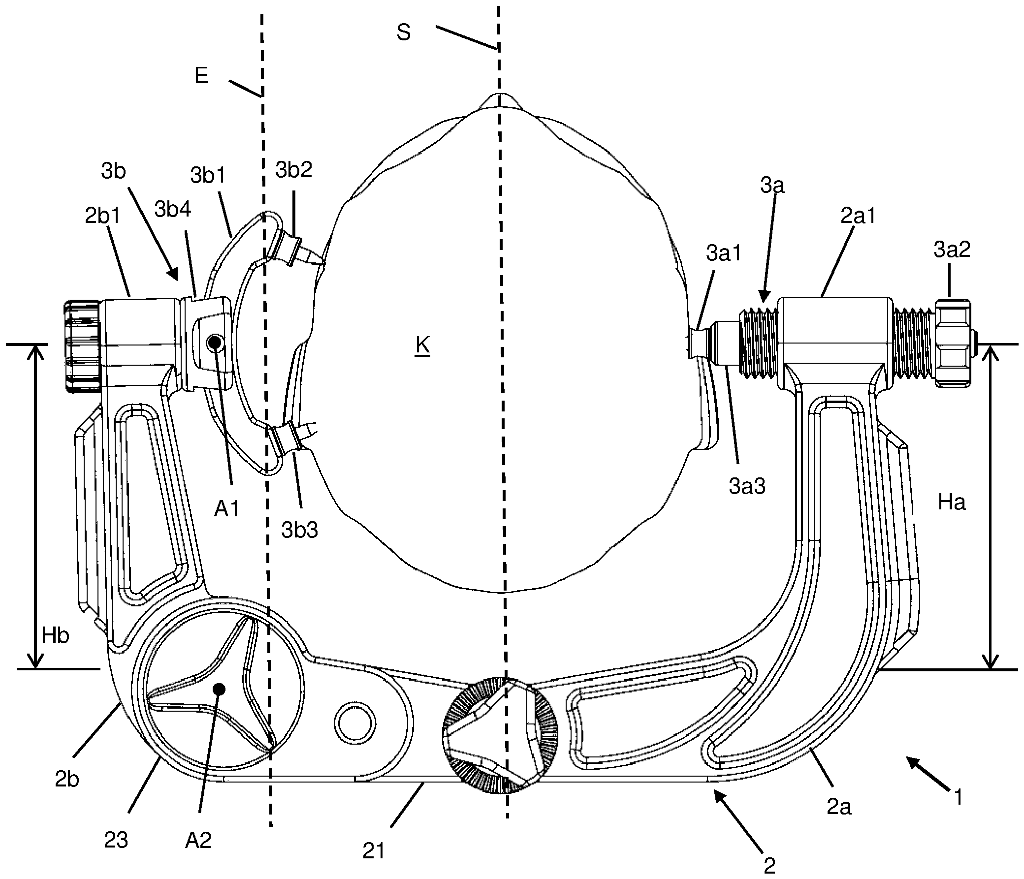
Die
Das im ersten Ende 2a1 befestigte erste Fixierelement 3a1 umfasst einen einzelnen Schädeldorn 3a1, welcher in einen axial verschieblichen Haltestift 3a3 eingesetzt ist. Der Haltestift 3a3 mit dem Schädeldorn 3a1 sind über eine Stellschraube 3a2, welche ein mit einem Innengewinde der Aufnahme im ersten Ende 2a1 kämmendes Außengewinde aufweist, axial verschiebbar.
Das im zweiten Ende 2b1 befestigte zweite Fixierelement 3b2 umfasst eine C-förmig gebogene Wippe 3b1 mit zwei Schädeldornen 3b2 und 3b3 an jedem ihrer Enden, welche in einer Wippenhalterung 3b4 um die Achse A1 verschwenkbar gelagert ist. Hierdurch kann sich das Fixierelement zum einen der Kopfform des Patienten anpassen um eine bessere Fixierung zu gewährleisten. Wesentlicher aber erübrigt sich durch diese Ausgestaltung eine exakte Ausrichtung der Fixierelemente derart, dass die radiale Verschieberichtung des ersten Fixierelements 3a, welche auch die Richtung ist, entlang der eine von diesem Fixierelement ausgeübte Klemmkraft wirkt, durch den Kraftschwerpunkt des gegenüberliegenden zweiten Fixierelements 3b gehen muss. Hätte das zweite Fixierelement ebenfalls nur einen einzelnen Schädeldorn oder wären die beiden Dorne fix und nicht auf einer schwenkbaren Wippe gelagert, wäre eine solche Ausrichtung unumgänglich, wenn ein die Kopfposition destabilisierendes Drehmoment vermieden werden soll. Durch die Schwenkbarkeit der Wippe kann sich das zur stabilen Einspannung nötige vektorielle Kräftegleichgewicht zwischen den an den drei Berührpunkten, den Schädeldornen 3a1, 3b2 und 3b3, auf den Kopf K wirkenden Klemmkräften von selbst einstellen.the
The first fixing element 3a1 fastened in the first end 2a1 comprises a single skull pin 3a1 which is inserted into an axially displaceable retaining pin 3a3. The retaining pin 3a3 with the skull pin 3a1 can be displaced axially via an adjusting screw 3a2, which has an external thread meshing with an internal thread of the receptacle in the first end 2a1.
The second fixing element 3b2 fastened in the second end 2b1 comprises a rocker 3b1 bent in a C-shape with two skull pins 3b2 and 3b3 at each of its ends, which is pivotably mounted in a rocker holder 3b4 about the axis A1. As a result, the fixing element can adapt to the shape of the patient's head in order to ensure better fixation. More importantly, however, this design eliminates the need for an exact alignment of the fixing elements in such a way that the radial displacement direction of the
Um die Fixierung des Kopfes schnell und einfach lösen zu können ist der C-Bogen 2 ähnlich, wie bei einigen Kopfklemmen im Stand der Technik bekannt, in einen ersten Teilbogen 2a und einen zweiten Teilbogen 2b unterteilt. Im Unterschied zu den bekannten Kopfklemmen sind die Teilbögen 2a und 2b jedoch über ein fixierbares Gelenk 23 um die Achse A2 gegeneinander schwenkbar verbunden. Die beiden Schwenkachsen A1 der Wippe und A2 der Teilbögen sind parallel zueinander und parallel zur Spiegelsymmetrieebene des Kopfes K, welche hier gleichzeitig eine Spiegelebene des C-Bogens 2 ist, ausgerichtet.In order to be able to release the fixation of the head quickly and easily, the C-
Das Gelenk 23 bzw. die Achse A2 dieses Gelenks liegen von der Spiegelebene S aus jenseits einer Ebene E, welche durch die Wippe 3b1 und eine Senkrechte auf die durch den C-Bogen 2 definierte Ebene festgelegt wird. Hierdurch ist vorteilhaft erreicht, dass das die vom Ende 2b1 des zweiten Teilbogens 2b radial nach innen zum Kopf des Patienten ragenden Teile des zweiten Fixierelements 3b, konkret die Wippe 3b1 mit den beiden Schädeldornen, beim Öffnen der Schnellverstellung der Kopfklemme 1 durch Verschwenken des Teilbogens 2b aus der dargestellten geschlossenen Position in eine nicht dargestellte offene Position sich zunächst nach oben bewegen, also ihre Überhöhung über dem Mittelteil 21 des C-Bogens 2 während des Schwenkens zunächst größer wird. Hierdurch können etwaig zwischen Patientenkopf K und C-Bogen 2 eingefügte Teile, etwa eine MRT Spule, vermieden werden, was einen wesentlichen Vorteil vor den Schnellverstellungen bekannter Kopfklemmen darstellt. Sofern der so erreichte Höhengewinn nicht ausreicht, um die Wippe 3b1 an einem solchen eingefügten Teil vorbeischwenken zu können, kann zusätzlich die Verschwenkbarkeit der Wippe 3b1 um die Achse A1 ausgenutzt werden.The joint 23 or the axis A2 of this joint lie beyond a plane E from the mirror plane S, which is defined by the rocker 3b1 and a perpendicular to the plane defined by the C-
Die vertikale Erstreckung Ha, Hb der Teilbögen 2a und 2b ist ausreichend groß gewählt, dass zwischen dem Kopf K und dem Mittelteil 21 des C-Bogens 2 ein ausreichender Abstand verbleibt, um Untersuchungsgeräte, wie beispielsweise eine MRT-Spule dort platzieren zu können. Insbesondere betragen Ha und Hb etwa 14-18 cm.The vertical extension Ha, Hb of the
In
Das erste Fixierelement 3a besteht aus Schädeldorn 3a1, der in einen Sitz im vorderen Ende von Haltestift 3a3 eingesetzt ist. An einem hinteren Stirnseite des vorderen Endes von Haltestift 3a3 sitzt im zusammengesetzten Zustand ein Ende der Spiralfeder 3a4 auf, deren anderes Ende an der inneren Stirnseite der hohlzylindrischen Schraubenhülse 3a2 anliegt. Die Schraubenhülse 3a2 hat an ihrer Außenseite ein Außengewinde 3a21, welches mit einem nur in
The
Das zweite Fixierelement 3b besteht aus der die beiden Schädeldorne 3b2 und 3b3 tragenden, C-förmig gebogenen Wippe 3b1, welche in der Halterung 3b4 um die Achse A1 schwenkbar gelagert ist. Die Wippenhalterung 3b4 wird mittels des durch die radial orientierte Öffnung bzw. Aufnahme im Ende 2b1 des zweiten Teilbogens gesteckten Stifts der Bolzenscheibe 3b5 befestigt.The
Das die Teilbögen 2a und 2b verbindende Gelenk 23 setzt sich zusammen aus einer Gabelelement 22, welches das dem ersten Ende 2a1 gegenüberliegende Ende des ersten Teilbogens 2a bildet und über eine Aussparung 220 verfügt, welche durch parallele Innenseiten begrenzt ist. In diese Aussparung 220 wird das komplementär geformte Kopplungsteil 24, welche das dem zweiten Ende 2b1 gegenüberliegende Ende des zweiten Teilbogens 2b bildet, so eingesteckt, das eine durchgängige Öffnung 240 des Kopplungsteil 24 und des Gabelelements 22 fluchten. Die Achse des Gelenks wird durch die hohlzylindrische Hülse der Konterhülsenscheibe 231 gebildet, welche den Bolzen der Gelenkbolzenscheibe 231 aufnimmt und hierdurch die Gelenkbolzenscheibe 231 kontert.The joint 23 connecting the
Der das Gelenk 23 fixierende, also verriegelnde, Ratschenmechanismus umfasst die Blattfeder 25, welche an der Unterseite des ersten Teilbogens 2a angebracht ist und soweit in die Ausnehmung 220 hineinragt, dass sie mit auf der gebogenen Stirnseite des Kopplungsteils 24 angeformten Reihe von Zähnen 241 zusammenwirken kann. Der vordere, die Zähne kontaktierende Teil der Blattfeder 25 ist durch den Entriegelungsknopf 26 im Zusammenwirken mit Stift 27 nach unten verbieg- und somit der Ratschenmechanismus entriegelbar.The ratchet mechanism that fixes, i.e. locks, the joint 23 comprises the
Das Einspannen des Kopfes in einer Kopfklemme gemäß der Ausführungsform aus den
In den
Die
Die Kopfklemme umfasst eine MRT Spule 5, welche in Schienen 521 des Haltetellers 52 eingeschoben und so fest mit diesem verbunden ist. Der Halteteller 52 hat, wie in
The head clamp includes an
Die obere Spule 5o ist nicht Teil der Klemmvorrichtung 1 und hier nur der Vollständigkeit halber dargestellt.The upper coil 5o is not part of the
Wie in
Da diese Ausführungsform in anderer Hinsicht der ersten, in den
Es wäre prinzipiell auch möglich, alternativ oder zusätzlich den ersten Teilbogen schwenkbar zu machen. Dies hat allerdings den Nachteil, dass sich die Klemmspannung der Spiralfeder des ersten Fixierelements beim schnellen Öffnen des C-Bogens schlagartig entladen würde, wodurch der Schädeldorn und/oder der ihn tragende Haltestift aus dem Fixierelement springen könnten.In principle, it would also be possible to make the first partial arc pivotable as an alternative or in addition. However, this has the disadvantage that the clamping tension of the spiral spring of the first fixing element would be discharged suddenly when the C-arm is opened quickly, as a result of which the skull pin and/or the retaining pin carrying it could jump out of the fixing element.
In
Ebenfalls zu sehen sind die Signalleitungen 55 und 55o der Spulen.The signal lines 55 and 55o of the coils can also be seen.
Wie aus den
In
BezugszeichenlisteReference List
- 11
- Kopfklemmehead clamp
- 22
- C-BogenC-arm
- 2a2a
- erster Teilbogenfirst partial arc
- 2a12a1
- erstes Ende mit Fixierelementaufnahmefirst end with fixing element receptacle
- 2a112a11
- Innengewinde in Aufnahme von 2a1Female thread in recording of 2a1
- 2b2 B
- zweiter Teilbogensecond partial arc
- 2b12b1
- zweites Ende mit Fixierelementaufnahmesecond end with fixing element holder
- 2121
- Mittelteilcenter part
- 2222
- Gabelfork
- 220220
- Aufnahme in 22recording in 22
- 2323
- Gelenkjoint
- 231231
- GelenkbolzenscheibePivot Bolt Washer
- 232232
- Konterhülsenscheibelock washer
- 2424
- Kopplungselementcoupling element
- 241241
- Zähne in Stirnseite von 24Teeth in face of 24
- 2525
- Feder feather
- 3a3a
- erstes Fixierelementfirst fixing element
- 3a13a1
- Schädeldorn von 3aSkull Pin from 3a
- 3a23a2
- Stellschraube(nhülse)adjusting screw (sleeve)
- 3a213a21
- Außengewindeexternal thread
- 3a33a3
- Haltestift für 3a1Holding pin for 3a1
- 3a43a4
- Spiralfederspiral spring
- 3b3b
- zweites Fixierelementsecond fixing element
- 3b13b1
- Wippeseesaw
- 3b2, 3b33b2, 3b3
- Schädeldorne von 3bSkull pins from 3b
- 3b43b4
- Wippenhalterungrocker bracket
- 3b53b5
- Bolzenscheibe zur Befestigung von 3b4 Bolt washer for attaching 3b4
- 55
- MRT SpuleMRI coil
- 5a, 5b, 5c5a, 5b, 5c
- klappbar verbundene Spulenteilehinged connected coil parts
- 5151
- Spulenfußcoil foot
- 511511
- Nutgroove
- 5252
- Haltetellerholding plate
- 521521
- Schienenrails
- 522522
- Beine legs
- A1A1
- erste Schwenkachsefirst pivot axis
- A2A2
- zweite Schwenkachsesecond pivot axis
- LL
- Verbindungslinie der Teile von 5line connecting the parts of 5
- KK
- Patientenkopfpatient head
- SS
- Spiegelsymmetrieebene von K (und 2)mirror symmetry plane of K (and 2)
- EE
- Wippenebenerocker level
Claims (15)
Priority Applications (1)
| Application Number | Priority Date | Filing Date | Title |
|---|---|---|---|
| DE102020119229.0A DE102020119229A1 (en) | 2020-07-21 | 2020-07-21 | Head clamp with two-piece C-arm |
Applications Claiming Priority (1)
| Application Number | Priority Date | Filing Date | Title |
|---|---|---|---|
| DE102020119229.0A DE102020119229A1 (en) | 2020-07-21 | 2020-07-21 | Head clamp with two-piece C-arm |
Publications (1)
| Publication Number | Publication Date |
|---|---|
| DE102020119229A1 true DE102020119229A1 (en) | 2022-01-27 |
Family
ID=79179088
Family Applications (1)
| Application Number | Title | Priority Date | Filing Date |
|---|---|---|---|
| DE102020119229.0A Withdrawn DE102020119229A1 (en) | 2020-07-21 | 2020-07-21 | Head clamp with two-piece C-arm |
Country Status (1)
| Country | Link |
|---|---|
| DE (1) | DE102020119229A1 (en) |
Cited By (1)
| Publication number | Priority date | Publication date | Assignee | Title |
|---|---|---|---|---|
| CN119700331A (en) * | 2025-02-26 | 2025-03-28 | 广州市文翰科学仪器有限公司 | A neurointervention head and neck support device |
-
2020
- 2020-07-21 DE DE102020119229.0A patent/DE102020119229A1/en not_active Withdrawn
Cited By (1)
| Publication number | Priority date | Publication date | Assignee | Title |
|---|---|---|---|---|
| CN119700331A (en) * | 2025-02-26 | 2025-03-28 | 广州市文翰科学仪器有限公司 | A neurointervention head and neck support device |
Similar Documents
| Publication | Publication Date | Title |
|---|---|---|
| DE69109817T2 (en) | Lockable bone plate system. | |
| DE60310561T2 (en) | Minimally invasive expanding spacer | |
| DE102012105264B4 (en) | Device for fixing a femur in hip endoprosthesis | |
| DE69928389T2 (en) | SPINE COLUMN OSTEOSYNTHESIS SYSTEM IN PARTICULAR FOR FRONT FIXATION | |
| DE69723108T2 (en) | ADJUSTABLE OSTEOSYNTHESIS DEVICE FOR THE SPINE AND POSITIONING TOOL | |
| EP3003198B1 (en) | Adapter device for an operating table | |
| DE60125928T2 (en) | EXTERNAL ONE WAY FIXATEUR | |
| DE69903505T2 (en) | Instrument for inserting a vertebral implant | |
| DE69917633T2 (en) | DEVICE FOR SECURING A SPIN BAR | |
| DE112014001466T5 (en) | Flexible arm and method of use | |
| DE3733924C2 (en) | Spine fixation device | |
| DE19841250C1 (en) | Head clamp for fixing patient's head e.g. for intro-operative X-ray diagnostics, has relatively pivoted frame elements secured in selected pivot position by ratchet element and co-operating ratchet disc | |
| EP0314021A2 (en) | Fixing device for parts of bones | |
| DE202009009503U1 (en) | Surgical spreader instrument | |
| EP2865346B1 (en) | Spinal stabilization system, medical equipment and medical device for the parallel alignment of medical instruments | |
| DE3234875A1 (en) | Device for preparing an operating area in surgery, especially in microsurgery | |
| DE102020119229A1 (en) | Head clamp with two-piece C-arm | |
| DE69713417T2 (en) | Transverse spine connector | |
| DE102012012545A1 (en) | Tracheal treatment platform for anesthetized mice | |
| DE19746687A1 (en) | Device for external fixation of broken bones, especially the extremities | |
| EP3244817A1 (en) | Device for carrying out a distraction or a compression of vertebral bodies during spinal surgery | |
| EP3988049B1 (en) | Distractor device | |
| DE102023109802A1 (en) | bone clamp | |
| DE19953827B4 (en) | Device for regulating the teeth | |
| DE29711401U1 (en) | Support and storage device |
Legal Events
| Date | Code | Title | Description |
|---|---|---|---|
| R082 | Change of representative |
Representative=s name: SCHARFENBERGER, BURKHARD, DR., DE |
|
| R119 | Application deemed withdrawn, or ip right lapsed, due to non-payment of renewal fee |