DE102019200612A1 - Device and method for calibrating a multiple-input-multiple-output radar sensor - Google Patents
Device and method for calibrating a multiple-input-multiple-output radar sensor Download PDFInfo
- Publication number
- DE102019200612A1 DE102019200612A1 DE102019200612.4A DE102019200612A DE102019200612A1 DE 102019200612 A1 DE102019200612 A1 DE 102019200612A1 DE 102019200612 A DE102019200612 A DE 102019200612A DE 102019200612 A1 DE102019200612 A1 DE 102019200612A1
- Authority
- DE
- Germany
- Prior art keywords
- target
- data
- radar sensor
- model
- targets
- Prior art date
- Legal status (The legal status is an assumption and is not a legal conclusion. Google has not performed a legal analysis and makes no representation as to the accuracy of the status listed.)
- Granted
Links
Images


Classifications
-
- G—PHYSICS
- G01—MEASURING; TESTING
- G01S—RADIO DIRECTION-FINDING; RADIO NAVIGATION; DETERMINING DISTANCE OR VELOCITY BY USE OF RADIO WAVES; LOCATING OR PRESENCE-DETECTING BY USE OF THE REFLECTION OR RERADIATION OF RADIO WAVES; ANALOGOUS ARRANGEMENTS USING OTHER WAVES
- G01S13/00—Systems using the reflection or reradiation of radio waves, e.g. radar systems; Analogous systems using reflection or reradiation of waves whose nature or wavelength is irrelevant or unspecified
- G01S13/02—Systems using reflection of radio waves, e.g. primary radar systems; Analogous systems
- G01S13/06—Systems determining position data of a target
- G01S13/42—Simultaneous measurement of distance and other co-ordinates
- G01S13/44—Monopulse radar, i.e. simultaneous lobing
- G01S13/4454—Monopulse radar, i.e. simultaneous lobing phase comparisons monopulse, i.e. comparing the echo signals received by an interferometric antenna arrangement
-
- G—PHYSICS
- G01—MEASURING; TESTING
- G01S—RADIO DIRECTION-FINDING; RADIO NAVIGATION; DETERMINING DISTANCE OR VELOCITY BY USE OF RADIO WAVES; LOCATING OR PRESENCE-DETECTING BY USE OF THE REFLECTION OR RERADIATION OF RADIO WAVES; ANALOGOUS ARRANGEMENTS USING OTHER WAVES
- G01S7/00—Details of systems according to groups G01S13/00, G01S15/00, G01S17/00
- G01S7/02—Details of systems according to groups G01S13/00, G01S15/00, G01S17/00 of systems according to group G01S13/00
- G01S7/40—Means for monitoring or calibrating
- G01S7/4004—Means for monitoring or calibrating of parts of a radar system
- G01S7/4026—Antenna boresight
-
- G—PHYSICS
- G01—MEASURING; TESTING
- G01S—RADIO DIRECTION-FINDING; RADIO NAVIGATION; DETERMINING DISTANCE OR VELOCITY BY USE OF RADIO WAVES; LOCATING OR PRESENCE-DETECTING BY USE OF THE REFLECTION OR RERADIATION OF RADIO WAVES; ANALOGOUS ARRANGEMENTS USING OTHER WAVES
- G01S13/00—Systems using the reflection or reradiation of radio waves, e.g. radar systems; Analogous systems using reflection or reradiation of waves whose nature or wavelength is irrelevant or unspecified
- G01S13/02—Systems using reflection of radio waves, e.g. primary radar systems; Analogous systems
- G01S13/06—Systems determining position data of a target
- G01S13/42—Simultaneous measurement of distance and other co-ordinates
- G01S13/426—Scanning radar, e.g. 3D radar
-
- G—PHYSICS
- G01—MEASURING; TESTING
- G01S—RADIO DIRECTION-FINDING; RADIO NAVIGATION; DETERMINING DISTANCE OR VELOCITY BY USE OF RADIO WAVES; LOCATING OR PRESENCE-DETECTING BY USE OF THE REFLECTION OR RERADIATION OF RADIO WAVES; ANALOGOUS ARRANGEMENTS USING OTHER WAVES
- G01S13/00—Systems using the reflection or reradiation of radio waves, e.g. radar systems; Analogous systems using reflection or reradiation of waves whose nature or wavelength is irrelevant or unspecified
- G01S13/88—Radar or analogous systems specially adapted for specific applications
- G01S13/93—Radar or analogous systems specially adapted for specific applications for anti-collision purposes
- G01S13/931—Radar or analogous systems specially adapted for specific applications for anti-collision purposes of land vehicles
-
- G—PHYSICS
- G01—MEASURING; TESTING
- G01S—RADIO DIRECTION-FINDING; RADIO NAVIGATION; DETERMINING DISTANCE OR VELOCITY BY USE OF RADIO WAVES; LOCATING OR PRESENCE-DETECTING BY USE OF THE REFLECTION OR RERADIATION OF RADIO WAVES; ANALOGOUS ARRANGEMENTS USING OTHER WAVES
- G01S7/00—Details of systems according to groups G01S13/00, G01S15/00, G01S17/00
- G01S7/02—Details of systems according to groups G01S13/00, G01S15/00, G01S17/00 of systems according to group G01S13/00
- G01S7/40—Means for monitoring or calibrating
- G01S7/4004—Means for monitoring or calibrating of parts of a radar system
- G01S7/4026—Antenna boresight
- G01S7/403—Antenna boresight in azimuth, i.e. in the horizontal plane
-
- G—PHYSICS
- G01—MEASURING; TESTING
- G01S—RADIO DIRECTION-FINDING; RADIO NAVIGATION; DETERMINING DISTANCE OR VELOCITY BY USE OF RADIO WAVES; LOCATING OR PRESENCE-DETECTING BY USE OF THE REFLECTION OR RERADIATION OF RADIO WAVES; ANALOGOUS ARRANGEMENTS USING OTHER WAVES
- G01S7/00—Details of systems according to groups G01S13/00, G01S15/00, G01S17/00
- G01S7/02—Details of systems according to groups G01S13/00, G01S15/00, G01S17/00 of systems according to group G01S13/00
- G01S7/40—Means for monitoring or calibrating
- G01S7/4004—Means for monitoring or calibrating of parts of a radar system
- G01S7/4026—Antenna boresight
- G01S7/4034—Antenna boresight in elevation, i.e. in the vertical plane
-
- G—PHYSICS
- G01—MEASURING; TESTING
- G01S—RADIO DIRECTION-FINDING; RADIO NAVIGATION; DETERMINING DISTANCE OR VELOCITY BY USE OF RADIO WAVES; LOCATING OR PRESENCE-DETECTING BY USE OF THE REFLECTION OR RERADIATION OF RADIO WAVES; ANALOGOUS ARRANGEMENTS USING OTHER WAVES
- G01S13/00—Systems using the reflection or reradiation of radio waves, e.g. radar systems; Analogous systems using reflection or reradiation of waves whose nature or wavelength is irrelevant or unspecified
- G01S13/02—Systems using reflection of radio waves, e.g. primary radar systems; Analogous systems
- G01S13/50—Systems of measurement based on relative movement of target
- G01S13/58—Velocity or trajectory determination systems; Sense-of-movement determination systems
- G01S13/583—Velocity or trajectory determination systems; Sense-of-movement determination systems using transmission of continuous unmodulated waves, amplitude-, frequency-, or phase-modulated waves and based upon the Doppler effect resulting from movement of targets
- G01S13/584—Velocity or trajectory determination systems; Sense-of-movement determination systems using transmission of continuous unmodulated waves, amplitude-, frequency-, or phase-modulated waves and based upon the Doppler effect resulting from movement of targets adapted for simultaneous range and velocity measurements
-
- G—PHYSICS
- G01—MEASURING; TESTING
- G01S—RADIO DIRECTION-FINDING; RADIO NAVIGATION; DETERMINING DISTANCE OR VELOCITY BY USE OF RADIO WAVES; LOCATING OR PRESENCE-DETECTING BY USE OF THE REFLECTION OR RERADIATION OF RADIO WAVES; ANALOGOUS ARRANGEMENTS USING OTHER WAVES
- G01S13/00—Systems using the reflection or reradiation of radio waves, e.g. radar systems; Analogous systems using reflection or reradiation of waves whose nature or wavelength is irrelevant or unspecified
- G01S13/88—Radar or analogous systems specially adapted for specific applications
- G01S13/93—Radar or analogous systems specially adapted for specific applications for anti-collision purposes
- G01S13/931—Radar or analogous systems specially adapted for specific applications for anti-collision purposes of land vehicles
- G01S2013/9327—Sensor installation details
- G01S2013/93271—Sensor installation details in the front of the vehicles
-
- G—PHYSICS
- G01—MEASURING; TESTING
- G01S—RADIO DIRECTION-FINDING; RADIO NAVIGATION; DETERMINING DISTANCE OR VELOCITY BY USE OF RADIO WAVES; LOCATING OR PRESENCE-DETECTING BY USE OF THE REFLECTION OR RERADIATION OF RADIO WAVES; ANALOGOUS ARRANGEMENTS USING OTHER WAVES
- G01S7/00—Details of systems according to groups G01S13/00, G01S15/00, G01S17/00
- G01S7/02—Details of systems according to groups G01S13/00, G01S15/00, G01S17/00 of systems according to group G01S13/00
- G01S7/40—Means for monitoring or calibrating
- G01S7/4052—Means for monitoring or calibrating by simulation of echoes
- G01S7/4082—Means for monitoring or calibrating by simulation of echoes using externally generated reference signals, e.g. via remote reflector or transponder
- G01S7/4091—Means for monitoring or calibrating by simulation of echoes using externally generated reference signals, e.g. via remote reflector or transponder during normal radar operation
Landscapes
- Engineering & Computer Science (AREA)
- Radar, Positioning & Navigation (AREA)
- Remote Sensing (AREA)
- Physics & Mathematics (AREA)
- Computer Networks & Wireless Communication (AREA)
- General Physics & Mathematics (AREA)
- Electromagnetism (AREA)
- Radar Systems Or Details Thereof (AREA)
Abstract
Die vorliegende Erfindung betrifft eine Vorrichtung zum Kalibrieren eines MIMO-Radarsensors , mit: einer Eingangsschnittstelle zum Empfangen einer Zieleliste des MIMO-Radarsensors mit Winkeldaten und Kanaldaten für mehrere Ziele in einer Umgebung eines Fahrzeugs, wobei die Winkeldaten Informationen zu einem Zielwinkel, unter dem sich ein Ziel befindet, umfassen und die Kanaldaten Informationen zu empfangenen Reflexionssignalen des Ziels in einzelnen Kanälen des MIMO-Radarsensors umfassen; einer Modellierungseinheit zum Erzeugen von Modelldaten für jedes Ziel der mehreren Ziele mit Informationen zu erwarteten Reflexionssignalen für eine angenommene Detektion eines Einzelziels unter dem Zielwinkel in einem Fernfeld des MIMO-Radarsensors basierend auf den Winkeldaten; einer Prozessoreinheit zum Ermitteln eines Modellfehlers für jedes Ziel der mehreren Ziele mit Informationen zu einer Abweichung zwischen den Kanaldaten und den Modelldaten des Ziels; einer Selektionseinheit zum Auswählen eines Ziels der mehreren Ziele basierend auf dem ermittelten Modellfehler, wobei der Modellfehler des ausgewählten Ziels im Vergleich zu den Modellfehlern der anderen Ziele klein ist; und einer Anpassungseinheit zum Ermitteln von Kalibrierungskoeffizienten mit Informationen zu einer Anpassung von Kanalausgängen der Kanäle des MIMO-Radarsensors basierend auf den Modelldaten und den Kanaldaten, wobei die Kalibrierungskoeffizienten die Abweichung der Kanaldaten von den Modelldaten kompensieren.
Description
Die vorliegende Erfindung betrifft eine Vorrichtung zum Kalibrieren eines Multiple-Input-Multiple-Output- (MIMO-) Radarsensors und ein entsprechendes Verfahren sowie ein System mit einem MIMO-Radarsensor und einer Vorrichtung.The present invention relates to a device for calibrating a multiple-input-multiple-output (MIMO) radar sensor and a corresponding method, as well as a system with a MIMO radar sensor and a device.
Moderne Fahrzeuge (Autos, Transporter, Lastwagen, Motorräder etc.) umfassen eine Vielzahl von Sensoren, die dem Fahrer Informationen zur Verfügung stellen und einzelne Funktionen des Fahrzeugs teil- oder vollautomatisiert steuern. Eine wichtige Voraussetzung ist hierbei die Erfassung, Erkennung und Modellierung der Umgebung des eigenen Fahrzeugs. Mittels Umgebungssensoren, wie beispielsweise Radar-, Lidar-, Ultraschall- und Kamerasensoren, werden Sensordaten mit Informationen zu der Umgebung erfasst. Ausgehend von den erfassten Daten sowie gegebenenfalls unter zusätzlicher Berücksichtigung im Fahrzeug verfügbarer Daten können dann Objekte in der Umgebung des Fahrzeugs identifiziert und klassifiziert werden. Basierend hierauf kann beispielsweise ein Verhalten eines autonomen oder teilautonomen Fahrzeugs an eine aktuelle Situation angepasst werden oder können dem Fahrer Zusatzinformationen zur Verfügung gestellt werden.Modern vehicles (cars, vans, trucks, motorcycles, etc.) include a large number of sensors that provide the driver with information and control individual functions of the vehicle in a partially or fully automated manner. An important prerequisite here is the acquisition, detection and modeling of the surroundings of your own vehicle. Using environmental sensors, such as radar, lidar, ultrasound and camera sensors, sensor data with information about the environment are recorded. On the basis of the recorded data and, if appropriate, with additional consideration of data available in the vehicle, objects in the surroundings of the vehicle can then be identified and classified. Based on this, a behavior of an autonomous or partially autonomous vehicle can be adapted to a current situation, for example, or additional information can be provided to the driver.
Ein weitverbreitetes Sensorprinzip ist dabei die Radartechnik. Radarsensoren für Fahrzeuge umfassen typischerweise mehrere Sende- und Empfangselemente und werden als Multiple-Input-Multiple-Output-Radare (MIMO-Radare) betrieben. Die Sende- und Empfangselemente bilden dabei virtuelle Kanäle des Radarsensors (Rx/Tx-Antennenpaare), wobei jeder Kanal eine andere Position repräsentiert. Durch eine Auswertung der Phasen- und Amplituden der Radarsignale an den verschiedenen Kanälen (Kanalantworten) kann eine Detektion eines Ziels (Winkellage in Azimut und Elevation, Doppler- bzw. Relativgeschwindigkeit und Abstand) erfolgen.Radar technology is a widespread sensor principle. Radar sensors for vehicles typically comprise several transmitting and receiving elements and are operated as multiple-input-multiple-output radars (MIMO radars). The transmit and receive elements form virtual channels of the radar sensor (Rx / Tx antenna pairs), each channel representing a different position. By evaluating the phase and amplitude of the radar signals on the different channels (channel responses), a target can be detected (angular position in azimuth and elevation, Doppler or relative speed and distance).
Bei der Produktion und Verarbeitung von Radarsensoren kommt es zu produktionsbedingten Unterschieden und Abweichungen. Zur Verbesserung der Signalqualität ist es daher üblich, jeden einzelnen Radarsensor nach der Produktion zu vermessen, um eine Kalibrierung der Kanalantworten zu erzielen. Oft findet die Kalibrierung erst statt, wenn der Radarsensor bereits im Fahrzeug verbaut ist. Hierzu wird üblicherweise in einer Messkammer ein Ziel unter dem Winkel von null Grad Azimut und Elevation erzeugt und die Kanalantwort gemessen. Diese besteht aus n komplexen Werten der n verfügbaren Kanäle, die für das entsprechende Ziel bei bekannter Position aus der Range/Doppler-Karte extrahiert werden. Ein Ziel bei null Grad sollte idealerweise in Amplitude und Phase die gleiche Antwort an allen Kanälen erzeugen. Die gemessenen Werte geben daher direkt die Abweichung für den entsprechenden Sensor wieder und können zur Normierung verwendet werden. Aus diesem Ansatz ergeben sich (komplexe) Kalibrierungskoeffizienten für die Kanäle. Diese Kalibrierungskoeffizienten werden anschließend angewendet, indem nach der Berechnung der Range/Doppler Karte durch diese dividiert wird.There are production-related differences and deviations in the production and processing of radar sensors. To improve the signal quality, it is therefore customary to measure each individual radar sensor after production in order to achieve a calibration of the channel responses. Calibration often only takes place when the radar sensor is already installed in the vehicle. For this purpose, a target is usually generated in a measuring chamber at an angle of zero degrees azimuth and elevation and the channel response is measured. This consists of n complex values of the n available channels, which are extracted from the Range / Doppler map for the corresponding target at a known position. A target at zero degrees should ideally produce the same response on all channels in amplitude and phase. The measured values therefore directly reflect the deviation for the corresponding sensor and can be used for standardization. This approach results in (complex) calibration coefficients for the channels. These calibration coefficients are then applied by dividing by the Range / Doppler map after it has been calculated.
Eine Herausforderung liegt darin, dass sich das Verhalten eines Radarsensors über seine Lebensdauer ändern kann. Durch Einwirkung von Faktoren, wie beispielsweise Temperaturänderungen, Feuchtigkeit, Erschütterungen etc. kann es insbesondere im Automotive-Bereich zu einer hohen Belastung und zu einer Degradation des Radarsensors kommen. Eine einmalig vorgenommene Kalibrierung kann sich stark verschlechtern und nach einer gewissen Zeit nur noch eine begrenzte Genauigkeit haben. Veränderungen innerhalb des Radarsensors können dabei sowohl langfristig, beispielsweise über mehrere Jahre, als auch kurzfristig, beispielsweise über wenige Minuten auftreten. Oft ist daher eine erneute (aufwändige) Kalibrierung oder auch ein (kostenintensiver) Austausch des Radarsensors erforderlich.One challenge is that the behavior of a radar sensor can change over its lifetime. The effects of factors such as temperature changes, moisture, vibrations, etc. can lead to high loads and degradation of the radar sensor, particularly in the automotive sector. A one-time calibration can deteriorate greatly and after a certain time can only have a limited accuracy. Changes within the radar sensor can occur both long-term, for example over several years, and short-term, for example over a few minutes. A renewed (complex) calibration or a (cost-intensive) replacement of the radar sensor is therefore often necessary.
Ausgehend hiervon stellt sich der vorliegenden Erfindung die Aufgabe, die Zuverlässigkeit und Genauigkeit bei einer Verwendung eines Radarsensors zu verbessern. Insbesondere sollen der Aufwand bzw. die Kosten für eine erneute Kalibrierung reduziert werden. Es soll eine Robustheit gegenüber einer Degradation des Radarsensors erreicht werden.Based on this, the object of the present invention is to improve the reliability and accuracy when using a radar sensor. In particular, the effort or the costs for a new calibration should be reduced. Robustness against degradation of the radar sensor is to be achieved.
Zum Lösen dieser Aufgabe betrifft die Erfindung in einem ersten Aspekt eine Vorrichtung zum Kalibrieren eines MIMO-Radarsensors, mit:
- einer Eingangsschnittstelle zum Empfangen einer Zieleliste des MIMO-Radarsensors mit Winkeldaten und Kanaldaten für mehrere Ziele in einer Umgebung eines Fahrzeugs, wobei die Winkeldaten Informationen zu einem Zielwinkel, unter dem sich ein Ziel befindet, umfassen und die Kanaldaten Informationen zu empfangenen Reflexionssignalen des Ziels in einzelnen Kanälen des MIMO-Radarsensors umfassen;
- einer Modellierungseinheit zum Erzeugen von Modelldaten für jedes Ziel der mehreren Ziele mit Informationen zu erwarteten Reflexionssignalen für eine angenommene Detektion eines Einzelziels unter dem Zielwinkel in einem Fernfeld des MIMO-Radarsensors basierend auf den Winkeldaten;
- einer Prozessoreinheit zum Ermitteln eines Modellfehlers für jedes Ziel der mehreren Ziele mit Informationen zu einer Abweichung zwischen den Kanaldaten und den Modelldaten des Ziels;
- einer Selektionseinheit zum Auswählen eines Ziels der mehreren Ziele basierend auf dem ermittelten Modellfehler, wobei der Modellfehler des ausgewählten Ziels im Vergleich zu den Modellfehlern der anderen Ziele klein ist; und
- einer Anpassungseinheit zum Ermitteln von Kalibrierungskoeffizienten mit Informationen zu einer Anpassung von Kanalausgängen der Kanäle des MIMO-Radarsensors basierend auf den Modelldaten und den Kanaldaten, wobei die Kalibrierungskoeffizienten die Abweichung der Kanaldaten von den Modelldaten kompensieren.
- an input interface for receiving a target list of the MIMO radar sensor with angle data and channel data for a plurality of targets in a surroundings of a vehicle, the angle data comprising information on a target angle at which a target is located and the channel data in detail on received reflection signals of the target Include channels of the MIMO radar sensor;
- a modeling unit for generating model data for each target of the plurality of targets with information on expected reflection signals for an assumed detection of a single target at the target angle in a far field of the MIMO radar sensor based on the angle data;
- a processor unit for determining a model error for each target of the plurality of targets with information on a discrepancy between the channel data and the model data of the target;
- a selection unit for selecting a target of the plurality of targets based on the determined model error, the model error of the selected target being small compared to the model errors of the other targets; and
- an adaptation unit for determining calibration coefficients with information for an adaptation of channel outputs of the channels of the MIMO radar sensor based on the model data and the channel data, the calibration coefficients compensating for the deviation of the channel data from the model data.
In einem weiteren Aspekt betrifft die vorliegende Erfindung ein System mit einem MIMO-Radarsensor und einer Vorrichtung wie zuvor beschrieben.In a further aspect, the present invention relates to a system with a MIMO radar sensor and a device as previously described.
Weitere Aspekte der Erfindung betreffen ein entsprechend der Vorrichtung ausgebildetes Verfahren und ein Computerprogrammprodukt mit Programmcode zum Durchführen der Schritte des Verfahrens, wenn der Programmcode auf einem Computer ausgeführt wird, sowie ein Speichermedium, auf dem ein Computerprogramm gespeichert ist, das, wenn es auf einem Computer ausgeführt wird, eine Ausführung des hierin beschriebenen Verfahrens bewirkt.Further aspects of the invention relate to a method designed in accordance with the device and a computer program product with program code for performing the steps of the method when the program code is executed on a computer, and a storage medium on which a computer program is stored, which if it is on a computer is carried out, the method described herein is carried out.
Bevorzugte Ausgestaltungen der Erfindung werden in den abhängigen Ansprüchen beschrieben. Es versteht sich, dass die vorgenannten und die nachstehend noch zu erläuternden Merkmale nicht nur in der jeweils angegebenen Kombination, sondern auch in anderen Kombinationen oder in Alleinstellung verwendbar sind, ohne den Rahmen der vorliegenden Erfindung zu verlassen. Insbesondere können die Vorrichtung, das System, das Verfahren und das Computerprogrammprodukt entsprechend der für die Vorrichtung und das System in den abhängigen Ansprüchen beschriebenen Ausgestaltungen ausgeführt sein.Preferred embodiments of the invention are described in the dependent claims. It goes without saying that the features mentioned above and those yet to be explained below can be used not only in the combination specified in each case, but also in other combinations or on their own without departing from the scope of the present invention. In particular, the device, the system, the method and the computer program product can be designed in accordance with the configurations described for the device and the system in the dependent claims.
Erfindungsgemäß werden die Sensordaten eines MIMO-Radarsensors empfangen. Die empfangene Zieleliste umfasst insbesondere den Azimut- und Elevationswinkel eines Ziels in einer Umgebung eines Fahrzeugs (Winkeldaten) sowie die Kanalantworten der verschiedenen Kanäle des MIMO-Radarsensors (Kanaldaten). Die Sensordaten werden vorzugsweise nach einer Vorverarbeitung durch den Radarsensor empfangen. Basierend auf den empfangenen Daten wird zunächst ein Modell eines angenommenen Einzelziels (Einzelzielmodell), das unter dem Zielwinkel des realen Ziels in einem Fernfeld des Radarsensors wahrgenommen wird, erzeugt. Es wird also ein Modell generiert, das den Kanaldaten entsprechende Modelldaten umfasst. In anderen Worten werden als Modelldaten simulierte ideale Kanalantworten für ein angenommenes Ziel unter dem (realen) Zielwinkel erzeugt. Für dieses angenommene Einzelziel wird ein Modellfehler berechnet. Dieser Modellfehler repräsentiert eine Abweichung zwischen dem realen Ziel bzw. den realen Daten (Kanaldaten) und dem simulierten Einzelziel bzw. den idealen Daten (Modelldaten). Im nächsten Schritt wird mindestens ein Ziel basierend auf dem ermittelten Modellfehler ausgewählt. Insbesondere wird ein Ziel ausgewählt, das einen im Vergleich zu den anderen Zielen kleinen Modellfehler aufweist. Bei diesem ausgewählten Ziel wird die Annahme getroffen, dass es sich bei dem realen Ziel tatsächlich um ein Einzelziel handelt. Diese Annahme bedeutet, dass die Abweichung zwischen Kanaldaten und Modelldaten einer ungenauen Kalibrierung entspricht. Es werden Kalibrierungskoeffizienten ermittelt, um die Ausgänge der Kanäle für zukünftige Messungen derart anzupassen, dass diese Abweichung kompensiert wird. In anderen Worten wird also der Radarsensor dahingehend kalibriert, dass die Kanalantworten bzw. die Kanalausgänge der Kanäle des MIMO-Radarsensors so modifiziert werden, dass die realen Daten dem Modell für ein ausgewähltes Ziel besser entsprechen.According to the invention, the sensor data of a MIMO radar sensor are received. The received target list includes in particular the azimuth and elevation angle of a target in a vehicle environment (angle data) and the channel responses of the various channels of the MIMO radar sensor (channel data). The sensor data are preferably received by the radar sensor after preprocessing. Based on the received data, a model of an assumed single target (single target model), which is perceived under the target angle of the real target in a far field of the radar sensor, is first generated. A model is therefore generated which comprises model data corresponding to the channel data. In other words, simulated ideal channel responses for an assumed target under the (real) target angle are generated as model data. A model error is calculated for this assumed single target. This model error represents a deviation between the real target or the real data (channel data) and the simulated single target or the ideal data (model data). In the next step, at least one target is selected based on the determined model error. In particular, a target is selected that has a small model error compared to the other targets. With this selected target, the assumption is made that the real target is actually a single target. This assumption means that the deviation between channel data and model data corresponds to an inaccurate calibration. Calibration coefficients are determined in order to adapt the outputs of the channels for future measurements in such a way that this deviation is compensated for. In other words, the radar sensor is calibrated in such a way that the channel responses or the channel outputs of the channels of the MIMO radar sensor are modified in such a way that the real data correspond better to the model for a selected target.
Die erfindungsgemäße Vorrichtung ermöglicht dadurch eine Kalibrierung eines Radarsensors während des Betriebs des Radarsensors. Insbesondere ist es möglich, dass die Kalibrierung ständig durchgeführt wird und eine laufende Aktualisierung der Kalibrierung erfolgt. Die Kalibrierungskoeffizienten für die Kanäle werden nach jeder Messung angepasst. Die im folgenden Zeitschritt ermittelten Kanaldaten werden dann basierend auf den neuen Kalibrierungskoeffizienten ermittelt bzw. vorverarbeitet. Hierdurch lassen sich Veränderungen im Sensor unmittelbar erkennen und kompensieren. Die Kalibrierungskoeffizienten entsprechen dabei den bei der Produktion ermittelten initialen Kalibrierungskoeffizienten und werden vorzugsweise zusätzlich zu diesen auf die Kanalausgänge angewendet. Insoweit ergibt sich eine zusätzliche Kalibrierung im Sinne einer Feinjustierung der Kanäle. Es können sowohl kurz- als auch langfristige Effekte kompensiert werden. Es ergibt sich eine verbesserte Detektion und eine genauere Zuordnung der Azimut- und Elevationswinkel zu einem Ziel. Eine höhere Genauigkeit wird erreicht.The device according to the invention thereby enables calibration of a radar sensor during operation of the radar sensor. In particular, it is possible for the calibration to be carried out continuously and for the calibration to be continuously updated. The calibration coefficients for the channels are adjusted after each measurement. The channel data determined in the following time step are then determined or preprocessed based on the new calibration coefficients. This allows changes in the sensor to be recognized and compensated for immediately. The calibration coefficients correspond to the initial calibration coefficients determined during production and are preferably applied to the channel outputs in addition to these. In this respect, there is an additional calibration in the sense of fine adjustment of the channels. Both short and long-term effects can be compensated for. The result is an improved detection and a more precise assignment of the azimuth and elevation angles to a target. A higher accuracy is achieved.
In einer bevorzugten Ausgestaltung ist die Modellierungseinheit zum Ermitteln eines Skalierungsvektors mit mittleren Skalierungsfaktoren für die einzelnen Kanäle des MIMO-Radarsensors basierend auf den Kanaldaten ausgebildet. Weiterhin ist die Modellierungseinheit zum Ermitteln einer Steuerungsmatrix basierend auf der Anordnung der Kanäle des MIMO-Radarsensors und den Winkeldaten ausgebildet. Zudem ist die Modellierungseinheit zum Erzeugen der Modelldaten basierend auf einer Multiplikation der Steuerungsmatrix mit dem Skalierungsvektor ausgebildet. Zunächst werden insbesondere eine mittlere Phase und Amplitude basierend auf den Kanaldaten geschätzt und ein entsprechender Skalierungsvektor ermittelt. Dann wird eine Steuerungsmatrix (kann auch als Steering Vector bezeichnet werden) berechnet, die die Anordnung der (virtuellen) Kanäle sowie den Winkel, unter dem ein Ziel wahrgenommen wurde, widerspiegelt. Die Steuerungsmatrix wird mit dem Skalierungsvektor multipliziert, um die Modelldaten zu ermitteln. Eine zutreffende Abbildung der Sensortopologie sowie der aktuellen Messwerte wird erzeugt. Zudem ergibt sich ein effizient berechenbarer Ansatz, der mit hoher Aktualisierungsfrequenz auch bei begrenzter Rechenleistung ausführbar ist.In a preferred embodiment, the modeling unit is designed to determine a scaling vector with average scaling factors for the individual channels of the MIMO radar sensor based on the channel data. Furthermore, the modeling unit is designed to determine a control matrix based on the arrangement of the channels of the MIMO radar sensor and the angle data. In addition, the modeling unit is designed to generate the model data based on a multiplication of the control matrix by the scaling vector. First of all, an average phase and amplitude are estimated based on the channel data and a corresponding one Scaling vector determined. A control matrix (also known as a steering vector) is then calculated, which reflects the arrangement of the (virtual) channels and the angle at which a target was perceived. The control matrix is multiplied by the scaling vector to determine the model data. An appropriate mapping of the sensor topology and the current measured values is generated. In addition, there is an efficiently calculable approach that can be carried out with a high update frequency even with limited computing power.
In einer bevorzugten Ausgestaltung ist die Prozessoreinheit zum Ermitteln eines mittleren quadratischen Fehlers über die Kanäle des MIMO-Radarsensors ausgebildet. Der Modellfehler wird als mittlerer quadratischer Fehler berechnet. Für jeden Kanal wird ein Fehler ermittelt und quadriert. Die Quadratwurzel des Mittelwerts entspricht dann dem quadratischen Mittelwert. Dieser quadratische Mittelwert dient als Maß für die Abweichung zwischen den Kanaldaten und den Modelldaten des Ziels. Es ergibt sich eine effizient berechenbare Möglichkeit für das Ermitteln des Modellfehlers. Eine einfache Bewertung der Abweichung zwischen Modell und Realität wird erreicht.In a preferred embodiment, the processor unit is designed to determine a mean square error via the channels of the MIMO radar sensor. The model error is calculated as a mean square error. An error is determined and squared for each channel. The square root of the mean then corresponds to the square mean. This root mean square serves as a measure of the deviation between the channel data and the model data of the target. The result is an efficiently calculable possibility for determining the model error. A simple assessment of the deviation between model and reality is achieved.
In einer vorteilhaften Ausgestaltung ist die Selektionseinheit zum Auswählen eines Ziels mit einem mittleren quadratischen Fehler, der unterhalb eines Schwellenwerts liegt, ausgebildet. Der Schwellenwert ist vorzugsweise vordefiniert. Ein Vergleich mit einem Schwellenwert stellt eine effiziente Möglichkeit für eine Bewertung dar. Lediglich Ziele, die einen mittleren quadratischen Fehler unterhalb eines Schwellenwerts aufweisen, werden weiter betrachtet. Eine einfache Berechenbarkeit wird erreicht.In an advantageous embodiment, the selection unit is designed to select a target with a mean square error that is below a threshold value. The threshold value is preferably predefined. A comparison with a threshold value is an efficient possibility for an evaluation. Only targets that have a mean square error below a threshold value are considered further. Easy predictability is achieved.
In einer vorteilhaften Ausgestaltung ist die Selektionseinheit zum Auswählen eines Ziels basierend auf einem Signal-Rausch-Verhältnis der empfangenen Reflexionssignale ausgebildet. Vorzugsweise wird ein Ziel mit einem Signal-Rausch-Verhältnis oberhalb eines Schwellenwerts ausgebildet. Es ist möglich, bei der Auswahl der Ziele zusätzlich ein Signal-Rausch-Verhältnis zu berücksichtigen. Lediglich starke Signale bzw. verhältnismäßig starke Signale werden dann bei der weiteren Prozessierung miteinbezogen. Es ergibt sich eine Verbesserung der Genauigkeit des Verfahrens, da die Wahrnehmung starker Ziele, also Ziele mit einem hohen Signal-Rausch-Verhältnis, verbessert bzw. genauer ist.In an advantageous embodiment, the selection unit is designed to select a target based on a signal-to-noise ratio of the received reflection signals. A target is preferably formed with a signal-to-noise ratio above a threshold. It is possible to take into account a signal-to-noise ratio when selecting the targets. Only strong signals or relatively strong signals are then included in the further processing. The accuracy of the method is improved since the perception of strong targets, that is to say targets with a high signal-to-noise ratio, is improved or more precise.
In einer vorteilhaften Ausgestaltung ist die Anpassungseinheit zum Ermitteln der Kalibrierungskoeffizienten basierend auf einem gleitenden Mittelwert ausgebildet. Durch die Verwendung eines gleitenden Mittelwerts kann eine Glättung über die Zeit erreicht werden. Es wird ständig in kleinen Schritten auf Veränderungen in den Kanalantworten des Radarsensors reagiert. Durch die Verwendung eines gleitenden Mittelwerts wird ein Fehler bzw. eine falsche Kalibrierung aufgrund von einmaligen Effekten vermieden.In an advantageous embodiment, the adaptation unit is designed to determine the calibration coefficients based on a moving average. Smoothing over time can be achieved by using a moving average. Small changes are constantly made to changes in the channel responses of the radar sensor. By using a moving average, an error or incorrect calibration due to one-off effects is avoided.
In einer vorteilhaften Ausgestaltung umfasst die Vorrichtung eine Verschiebungskompensationseinheit zum Bestimmen einer Winkelverschiebung basierend auf den Kalibrierungskoeffizienten und zum Berechnen und Anwenden eines Kompensationsfaktors auf die Kalibrierungskoeffizienten, wenn die Winkelverschiebung über einem Schwellenwert liegt. Der Schwellenwert ist erneut vorzugsweise vordefiniert. Die Verschiebungskompensationseinheit ist in anderen Worten dazu ausgebildet, einen Drift zu kompensieren, der sich bei der Anwendung der Kalibrierungskoeffizienten ergeben kann. Ein erfindungsgemäßes Verfahren kann dazu führen, dass der Nullpunkt des Radarsensors im Laufe der Zeit verschoben wird. Sofern eine derartige Verschiebung erkannt wird, wird eine Kompensation vorgenommen. Das System wird erneut in Richtung des ursprünglich eingestellten Nullpunkts hin ausgerichtet. Dies hat den Vorteil, dass eine langfristige Genauigkeit sichergestellt wird.In an advantageous embodiment, the device comprises a displacement compensation unit for determining an angular displacement based on the calibration coefficients and for calculating and applying a compensation factor to the calibration coefficients if the angular displacement lies above a threshold value. The threshold value is again preferably predefined. In other words, the displacement compensation unit is designed to compensate for a drift that can result when the calibration coefficients are applied. A method according to the invention can lead to the zero point of the radar sensor being shifted over time. If such a shift is detected, compensation is carried out. The system is re-aligned towards the originally set zero point. This has the advantage of ensuring long-term accuracy.
Bevorzugt ist die Verschiebungskompensationseinheit dabei zum Durchführen eines Beamformings für einen Nullpunkt und für Punkte in einer Nachbarschaft des Nullpunkts basierend auf den Kalibrierungskoeffizienten ausgebildet. Vorzugsweise weisen alle Punkte in der Nachbarschaft des Nullpunkts denselben Winkelabstand zum Nullpunkt auf. Weiterhin ist die Verschiebungskompensationseinheit zum Berechnen und Anwenden des Kompensationsfaktors ausgebildet, wenn die betragsmäßige Antwort des Beamformings für einen Punkt in der Nachbarschaft des Nullpunkts größer ist als die betragsmäßige Antwort des Beamformings für den Nullpunkt. Eine direkte Nachbarschaft kann beispielsweise durch einen 0,02 Grad Abstand in Azimut und/oder Elevation definiert sein. Sofern festgestellt wird, dass ein Beamforming an einer dieser Stellen in der Nachbarschaft des Nullpunkts eine betragsmäßig größere Antwort als der Nullpunkt selbst liefert, wird eine Justierung vorgenommen. Insbesondere ist es möglich, dass die Werte der festgestellten Richtung mit der betragsmäßig größten Kanalantwort als Basis für die Berechnung eines Quotienten zum Anwenden auf die Kalibrierungskoeffizienten verwendet wird. Eine langfristige Genauigkeit bleibt sichergestellt. Eine Abweichung im Sinne eines Bias wird vermieden.The displacement compensation unit is preferably designed to carry out beamforming for a zero point and for points in a neighborhood of the zero point based on the calibration coefficients. All points in the vicinity of the zero point preferably have the same angular distance from the zero point. Furthermore, the displacement compensation unit is designed to calculate and apply the compensation factor if the magnitude response of the beamforming for a point in the vicinity of the zero point is greater than the magnitude response of the beamforming for the zero point. A direct neighborhood can be defined, for example, by a distance of 0.02 degrees in azimuth and / or elevation. If it is determined that beamforming at one of these points in the vicinity of the zero point provides a larger answer than the zero point itself, an adjustment is made. In particular, it is possible that the values of the determined direction with the largest channel response in terms of amount are used as the basis for the calculation of a quotient for application to the calibration coefficients. Long-term accuracy remains guaranteed. A deviation in the sense of a bias is avoided.
In einer weiteren vorteilhaften Ausgestaltung ist die Verschiebungskompensationseinheit zum Berechnen des Kompensationsfaktors basierend auf einer Hälfte eines Winkels zwischen dem Nullpunkt und dem Punkt in der Nachbarschaft des Nullpunkts mit der betragsmäßig höchsten Antwort des Beamformings ausgebildet. Vorzugsweise kann eine Mitte zwischen dem Nullpunkt und dem ermittelten Punkt mit der betragsmäßig höchsten Antwort als Grundlage für die Neueinstellung bzw. Feinkalibrierung verwendet werden. Eine langfristige Genauigkeit bleibt behalten.In a further advantageous embodiment, the displacement compensation unit for calculating the compensation factor is based on a half of an angle between the zero point and the point in the vicinity of the zero point with the highest response of the Beamformings trained. A center between the zero point and the point determined with the highest answer in terms of amount can preferably be used as the basis for the new adjustment or fine calibration. Long-term accuracy is retained.
In einer weiteren vorteilhaften Ausgestaltung ist die Anpassungseinheit zum Ermitteln der Kalibrierungskoeffizienten eines vorigen Zeitschritts ausgebildet, wenn basierend auf der Zieleliste festgestellt wird, dass sich das Fahrzeug nicht bewegt. Es kann zu Fehlern führen, wenn immer dieselben Ziele berücksichtigt werden. Daher ist es möglich, dass die erfindungsgemäße Feinkalibrierung temporär deaktiviert wird, wenn bei stehendem Fahrzeug immer die gleichen Ziele über lange Zeit detektiert werden. Hierdurch wird sichergestellt, dass sich keine konstanten Fehler bei der Ermittlung der Kalibrierungskoeffizienten fortpflanzen. Eine langfristige Genauigkeit und eine zielgerichtete Kalibrierung werden sichergestellt.In a further advantageous embodiment, the adaptation unit is designed to determine the calibration coefficients of a previous time step if it is determined based on the target list that the vehicle is not moving. Errors can occur if the same goals are always taken into account. It is therefore possible that the fine calibration according to the invention is temporarily deactivated if the same targets are always detected for a long time when the vehicle is stationary. This ensures that no constant errors propagate when determining the calibration coefficients. Long-term accuracy and targeted calibration are ensured.
In einer weiteren vorteilhaften Ausgestaltung ist die Modellierungseinheit zum Erzeugen der Modelldaten basierend auf einem Einfluss der einzelnen Kanäle aufeinander ausgebildet. Es ist möglich, dass bei der Modellierung keine eindeutige Beziehung zwischen einer Kanalantwort und einem einzelnen Kalibrierungskoeffizienten verwendet wird, sondern eine allgemeinere Modellierung aufgestellt wird. Insbesondere kann der Einfluss benachbarter Kanäle aufeinander berücksichtigt werden. Dies führt zu einer weiter verbesserten Genauigkeit bei der Erzeugung der Modelldaten (Modellierung).In a further advantageous embodiment, the modeling unit is designed to generate the model data based on an influence of the individual channels on one another. It is possible that the modeling does not use a clear relationship between a channel response and a single calibration coefficient, but rather a more general modeling is established. In particular, the influence of adjacent channels on one another can be taken into account. This leads to a further improved accuracy in the generation of the model data (modeling).
In einer vorteilhaften Ausgestaltung des Systems ist der MIMO-Radarsensor zum Aussenden und Empfangen von Radarsignalen in einem Frequenzbereich von 70 GHz bis 80 GHz, bevorzugt von 77 GHz ausgebildet. Diese Frequenzen haben sich als besonders vorteilhaft für die Verwendung im Automotivebereich herausgestellt.In an advantageous embodiment of the system, the MIMO radar sensor is designed to transmit and receive radar signals in a frequency range from 70 GHz to 80 GHz, preferably from 77 GHz. These frequencies have proven to be particularly advantageous for use in the automotive sector.
Ein Radarsensor sendet ein Radarsignal aus und empfängt Reflexionen des Radarsignals an Objekten innerhalb eines Sichtbereichs des Radarsensors. Der Sichtbereich bezeichnet dabei ein Gebiet, innerhalb dessen Objekte erfasst werden können. Eine Umgebung eines Fahrzeugs umfasst insbesondere einen von einem am Fahrzeug angebrachten Radarsensor aus sichtbaren Bereich im Umfeld des Fahrzeugs. Ein Radarsensor kann auch mehrere Einzelsensoren umfassen, die beispielsweise eine 360 Grad-Rundumsicht ermöglichen und somit ein vollständiges Abbild der Umgebung des Fahrzeugs aufzeichnen können. Die Sensordaten eines Radarsignals umfassen insbesondere einen Abstand, eine Punktgeschwindigkeit, die einer Mikro-Doppler-Information entspricht, einen Elevationswinkel und einen Azimutwinkel für verschiedene Detektionen des Radarsensors. Unter einem Scanpunkt wird ein einzelner Punkt, also eine einzelne Detektion mit den o.g. Informationen verstanden. Üblicherweise werden während eines Messzyklus des Radarsensors eine Vielzahl an Scanpunkten erzeugt. Unter einem Messzyklus wird ein einmaliges Durchlaufen des sichtbaren Bereichs verstanden. Die in einem Messzyklus erfassten Scanpunkte können als Zieleliste (Radar Target List) bezeichnet werden. Die hierin genannten Werte und Koeffizienten können jeweils Vektorgrößen sein, die mehrere Werte umfassen. Es ist möglich, dass die Koeffizienten und Werte hierin komplexe Werte sind.A radar sensor emits a radar signal and receives reflections of the radar signal on objects within a field of view of the radar sensor. The field of view denotes an area within which objects can be detected. An environment of a vehicle comprises in particular an area in the surroundings of the vehicle that is visible from a radar sensor attached to the vehicle. A radar sensor can also comprise a plurality of individual sensors which, for example, enable a 360-degree all-round view and can therefore record a complete image of the surroundings of the vehicle. The sensor data of a radar signal include in particular a distance, a point speed, which corresponds to micro-Doppler information, an elevation angle and an azimuth angle for various detections of the radar sensor. Under a scan point, a single point, i.e. a single detection with the above Understood information. A large number of scan points are usually generated during a measurement cycle of the radar sensor. A measuring cycle is understood to mean a single passage through the visible area. The scan points recorded in a measurement cycle can be referred to as a radar target list. The values and coefficients mentioned herein can each be vector sizes that comprise several values. It is possible that the coefficients and values herein are complex values.
Die Erfindung wird nachfolgend anhand einiger ausgewählter Ausführungsbeispiele im Zusammenhang mit den beiliegenden Zeichnungen näher beschrieben und erläutert. Es zeigen:
-
1 eine schematische Darstellung eines erfindungsgemäßen Systems in einem Fahrzeug in einer Umgebung; -
2 eine schematische Darstellung einer erfindungsgemäßen Vorrichtung; -
3a ,3b eine schematische Darstellung einer erfindungsgemäßen Datenverarbeitung; -
4 eine schematische Darstellung einer erfindungsgemäßen Verschiebungskompensation; und -
5 eine schematische Darstellung eines erfindungsgemäßen Verfahrens.
-
1 a schematic representation of a system according to the invention in a vehicle in an environment; -
2nd a schematic representation of a device according to the invention; -
3a ,3b a schematic representation of a data processing according to the invention; -
4th a schematic representation of a displacement compensation according to the invention; and -
5 a schematic representation of a method according to the invention.
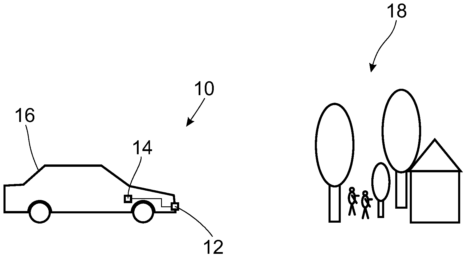
In der
Bei Inbetriebnahme eines derartigen MIMO-Radarsensors
In der
Die Vorrichtung
Weiterhin umfasst die erfindungsgemäße Vorrichtung
Weiterhin umfasst die Vorrichtung
Für die Herleitung des MSE wird hierbei angenommen, dass sich ein Vektor x der Signal-Kanal-Antworten für ein Ziel ergibt:
![]()
![]()
Hierbei ist Anm die Steuerungsmatrix (Steering-Matrix), die aus dem Raumwinkel δ erstellt wird. Die Dimension n entspricht dabei der Anzahl der Kanäle, die Dimension m entspricht der Anzahl von (Punkt-) Zielen, die zum Signal beitragen. Der unbekannte Vektor s von komplexen Skalierungsfaktoren (Skalierungsvektor) weist eine Länge m auf. Die einzelnen Skalierungsfaktoren entsprechen der Amplitude und Phasenverschiebung der m Punktziele. Zudem ergibt sich ein Rauschanteil σ. Der für die Kalibrierung betrachtete Modellfehler (Einzelzielfehler) und die entsprechenden Modelle (Einzelzielmodelle) gehen aus den Gleichungen für m=1 hervor.Note is the steering matrix, which is created from the solid angle δ. The dimension n corresponds to the number of channels, the dimension m corresponds to the number of (point) targets that contribute to the signal. The unknown vector s of complex scaling factors (scaling vector) has a length m. The individual scaling factors correspond to the amplitude and phase shift of the m point targets. There is also a noise component σ. The model error (single target error) considered for the calibration and the corresponding models (single target models) result from the equations for m = 1.
Der Skalierungsvektor s kann als mittlere Skalierung ŝ aus dem gemessenen Signal geschätzt werden gemäß
![]()
![]()
Hierbei bezeichnet A+ die Pseudoinverse der Steuerungsmatrix A. Ausgehend hiervon ergibt sich als Modellsignal für das Einzelziel (Modelldaten) bei Normierung auf das Eingangssignal (Kanaldaten)
![]()
![]()
Der Modellfehler kann dann als mittlerer quadratischer Fehler zwischen Kanaldaten und Modelldaten gemäß
![]()
![]()
In den
In der
Zurückkommend auf die
Bei dieser Auswahl des Ziels in der Selektionseinheit
In einer Anpassungseinheit
Da die getroffenen Annahmen für ein einzelnes Ziel nur bedingt erfüllt sein können (reale Ziele können beispielsweise aufgrund ihrer Ausdehnung nur in Ausnahmefällen ein ideales Einzelziel darstellen), ist die Anpassungseinheit
Die erfindungsgemäße Vorrichtung
In der
Die Anpassungseinheit
Optional ist es möglich, dass eine Schätzung der Antennenposition vorgenommen wird. Wenn der Kalibrierfehler nur über einen komplexen Faktor kompensiert wird, kann man mit entsprechender Amplitude und Phase die Abweichung der Zuleitungen kompensieren (Dämpfung und Länge). Ebenfalls ist es möglich, direkt eine Verschiebung des virtuellen Antennenarrays zu schätzen. Beispielsweise kann als Abwandlung der Schnitt der einfallenden Einzelziel-Wellenfront mit der Antennenebene betrachtet werden. Ein verbleibender Feinkalibrierfehler kann dann durch Verschiebung senkrecht zum Schnitt kompensiert werden. Hierbei ist anzumerken, dass diese Ansätze Ziele in verschiedenen Richtungen benötigen, um eine Kompensation der Antennenstruktur in allen Richtungen umzusetzen.It is optionally possible for the antenna position to be estimated. If the calibration error is only compensated by a complex factor, the deviation of the supply lines (attenuation and length) can be compensated with the appropriate amplitude and phase. It is also possible to directly estimate a shift in the virtual antenna array. For example, the intersection of the incident single-target wavefront with the antenna plane can be considered as a modification. A remaining fine calibration error can then be compensated for by shifting perpendicular to the cut. It should be noted that these approaches require targets in different directions in order to implement compensation of the antenna structure in all directions.
Optional ist es weiterhin möglich, eine Schätzung des Einflusses benachbarter Zuleitungen mit einzubeziehen. Anstatt eine eindeutige Beziehung zwischen der jeweiligen Kanalantwort und einem Kalibrierungskoeffizienten herzustellen, kann auch eine allgemeinere Modellierung der Kanäle aufgestellt werden. Insbesondere kann bei der Modellierung der Einfluss eines Kanals auf einen benachbarten Kanal (Zuleitungen) berücksichtigt werden. Hierzu sind dann mehrere Messungen erforderlich, um ein Gleichungssystem mit mehreren unbekannten (komplexen) Skalierungsfaktoren zwischen den Kanälen zu lösen. Grundsätzlich bleibt der zuvor beschriebene Ansatz aber unverändert.Optionally, it is also possible to include an estimate of the influence of neighboring supply lines. Instead of establishing a clear relationship between the respective channel response and a calibration coefficient, a more general modeling of the channels can also be established. In particular, the influence of a channel on an adjacent channel (supply lines) can be taken into account in the modeling. This requires several measurements to solve a system of equations with several unknown (complex) scaling factors between the channels. Basically, the approach described above remains unchanged.
In der
Die Erfindung wurde anhand der Zeichnungen und der Beschreibung umfassend beschrieben und erklärt. Die Beschreibung und Erklärung sind als Beispiel und nicht einschränkend zu verstehen. Die Erfindung ist nicht auf die offenbarten Ausführungsformen beschränkt. Andere Ausführungsformen oder Variationen ergeben sich für den Fachmann bei der Verwendung der vorliegenden Erfindung sowie bei einer genauen Analyse der Zeichnungen, der Offenbarung und der nachfolgenden Patentansprüche.The invention has been described and explained comprehensively with reference to the drawings and the description. The description and explanation are to be understood as examples and not restrictive. The invention is not limited to the disclosed embodiments. Other embodiments or variations will occur to those skilled in the art using the present invention, as well as upon a detailed analysis of the drawings, the disclosure, and the following claims.
In den Patentansprüchen schließen die Wörter „umfassen“ und „mit“ nicht das Vorhandensein weiterer Elemente oder Schritte aus. Der undefinierte Artikel „ein“ oder „eine“ schließt nicht das Vorhandensein einer Mehrzahl aus. Ein einzelnes Element oder eine einzelne Einheit kann die Funktionen mehrerer der in den Patentansprüchen genannten Einheiten ausführen. Ein Element, eine Einheit, eine Schnittstelle, eine Vorrichtung und ein System können teilweise oder vollständig in Hard- und/oder in Software umgesetzt sein. Die bloße Nennung einiger Maßnahmen in mehreren verschiedenen abhängigen Patentansprüchen ist nicht dahingehend zu verstehen, dass eine Kombination dieser Maßnahmen nicht ebenfalls vorteilhaft verwendet werden kann. Ein Computerprogramm kann auf einem nichtflüchtigen Datenträger gespeichert/vertrieben werden, beispielsweise auf einem optischen Speicher oder auf einem Halbleiterlaufwerk (SSD). Ein Computerprogramm kann zusammen mit Hardware und/oder als Teil einer Hardware vertrieben werden, beispielsweise mittels des Internets oder mittels drahtgebundener oder drahtloser Kommunikationssysteme. Bezugszeichen in den Patentansprüchen sind nicht einschränkend zu verstehen.In the claims, the words "comprise" and "with" do not exclude the presence of further elements or steps. The undefined article "a" or "an" does not exclude the existence of a plurality. A single element or a single unit can perform the functions of several of the units mentioned in the claims. An element, a unit, an interface, a device and a system can be partially or completely implemented in hardware and / or in software. The mere mention of some measures in several different dependent claims is not to be understood to mean that a combination of these measures cannot also be used advantageously. A computer program can be stored / distributed on a non-volatile data carrier, for example on an optical memory or on a semiconductor drive (SSD). A computer program can be distributed together with hardware and / or as part of hardware, for example by means of the Internet or by means of wired or wireless communication systems. Reference signs in the claims are not to be understood as restrictive.
BezugszeichenlisteReference list
- 1010th
- Systemsystem
- 1212th
- MIMO-RadarsensorMIMO radar sensor
- 1414
- Vorrichtungcontraption
- 1616
- Fahrzeugvehicle
- 1818th
- Objektobject
- 2020
- EingangsschnittstelleInput interface
- 2222
- ModellierungseinheitModeling unit
- 2424th
- ProzessoreinheitProcessor unit
- 2626
- AntennenanordnungAntenna arrangement
- 2828
- SelektionseinheitSelection unit
- 3030th
- AnpassungseinheitAdjustment unit
- 3232
- VerschiebungskompensationseinheitDisplacement compensation unit
Claims (15)
Priority Applications (5)
| Application Number | Priority Date | Filing Date | Title |
|---|---|---|---|
| DE102019200612.4A DE102019200612B4 (en) | 2019-01-18 | 2019-01-18 | Apparatus and method for calibrating a multiple-input-multiple-output radar sensor |
| PCT/EP2020/050516 WO2020148179A1 (en) | 2019-01-18 | 2020-01-10 | Device and method for calibrating a multiple-input multiple output radar sensor |
| JP2021541540A JP7439105B2 (en) | 2019-01-18 | 2020-01-10 | Calibration device and method for multi-input-multi-output radar sensor |
| US17/423,828 US12066568B2 (en) | 2019-01-18 | 2020-01-10 | Device and method for calibrating a multiple-input multiple output radar sensor |
| CN202080009637.0A CN113330326B (en) | 2019-01-18 | 2020-01-10 | Apparatus and method for calibrating a multiple-input multiple-output radar sensor |
Applications Claiming Priority (1)
| Application Number | Priority Date | Filing Date | Title |
|---|---|---|---|
| DE102019200612.4A DE102019200612B4 (en) | 2019-01-18 | 2019-01-18 | Apparatus and method for calibrating a multiple-input-multiple-output radar sensor |
Publications (2)
| Publication Number | Publication Date |
|---|---|
| DE102019200612A1 true DE102019200612A1 (en) | 2020-07-23 |
| DE102019200612B4 DE102019200612B4 (en) | 2025-06-12 |
Family
ID=69159781
Family Applications (1)
| Application Number | Title | Priority Date | Filing Date |
|---|---|---|---|
| DE102019200612.4A Active DE102019200612B4 (en) | 2019-01-18 | 2019-01-18 | Apparatus and method for calibrating a multiple-input-multiple-output radar sensor |
Country Status (5)
| Country | Link |
|---|---|
| US (1) | US12066568B2 (en) |
| JP (1) | JP7439105B2 (en) |
| CN (1) | CN113330326B (en) |
| DE (1) | DE102019200612B4 (en) |
| WO (1) | WO2020148179A1 (en) |
Cited By (3)
| Publication number | Priority date | Publication date | Assignee | Title |
|---|---|---|---|---|
| EP4293382A1 (en) | 2022-06-17 | 2023-12-20 | Volkswagen Ag | Method and control unit for intrinsic calibration of a radar device for a vehicle |
| US12066568B2 (en) | 2019-01-18 | 2024-08-20 | Zf Friedrichshafen Ag | Device and method for calibrating a multiple-input multiple output radar sensor |
| WO2025082757A1 (en) * | 2023-10-18 | 2025-04-24 | Robert Bosch Gmbh | Method for adjusting a vertical principal axis of sound emission and sound reception |
Families Citing this family (10)
| Publication number | Priority date | Publication date | Assignee | Title |
|---|---|---|---|---|
| EP3729228A4 (en) * | 2019-03-12 | 2020-12-02 | SZ DJI Technology Co., Ltd. | Method and apparatus for detecting radar wave offset |
| CN113287036B (en) * | 2019-09-30 | 2022-09-09 | 华为技术有限公司 | A method for velocity deblurring and echo signal processing device |
| US20230082442A1 (en) * | 2021-09-13 | 2023-03-16 | Gm Cruise Holdings Llc | Radar calibration device |
| EP4187276A1 (en) * | 2021-11-30 | 2023-05-31 | Aptiv Technologies Limited | Method and system for estimating a radar calibration matrix |
| DE102021214515A1 (en) * | 2021-12-16 | 2023-06-22 | Robert Bosch Gesellschaft mit beschränkter Haftung | Procedure for calibrating a radar sensor |
| DE102022209121A1 (en) * | 2022-09-02 | 2024-03-07 | Robert Bosch Gesellschaft mit beschränkter Haftung | Method for self-calibration of a radar system |
| CN116359879A (en) * | 2023-03-28 | 2023-06-30 | 深圳北醒科技有限公司 | Coupling Method of Radar Receiving System |
| CN119199762A (en) * | 2023-06-27 | 2024-12-27 | 南京隼眼电子科技有限公司 | Radar channel calibration method, device and storage medium |
| CN116819469B (en) * | 2023-08-28 | 2023-11-10 | 南京慧尔视智能科技有限公司 | Multi-radar target position synchronization method, device, equipment and storage medium |
| CN120760755A (en) * | 2025-07-30 | 2025-10-10 | 大连交通大学 | Intelligent pan-tilt three-point ranging parallel calibration system and method |
Family Cites Families (19)
| Publication number | Priority date | Publication date | Assignee | Title |
|---|---|---|---|---|
| DE19962997B4 (en) * | 1999-12-24 | 2010-06-02 | Robert Bosch Gmbh | Method for calibrating a sensor system |
| US6937592B1 (en) * | 2000-09-01 | 2005-08-30 | Intel Corporation | Wireless communications system that supports multiple modes of operation |
| US6940917B2 (en) * | 2002-08-27 | 2005-09-06 | Qualcomm, Incorporated | Beam-steering and beam-forming for wideband MIMO/MISO systems |
| CN102816883B (en) * | 2012-06-18 | 2013-12-11 | 北京科技大学 | Radar, video and laser system combined device for measuring blast furnace burden surface |
| DE102014208899A1 (en) * | 2014-05-12 | 2015-11-12 | Robert Bosch Gmbh | Method for calibrating a MIMO radar sensor for motor vehicles |
| US10270547B2 (en) * | 2015-03-12 | 2019-04-23 | University Of Notre Dame Du Lac | Method and apparatus for sinusoid detection |
| US10396865B2 (en) * | 2015-03-19 | 2019-08-27 | Commscope Technologies Llc | Spectral analysis signal identification |
| SE541664C2 (en) * | 2015-10-23 | 2019-11-19 | Qamcom Tech Ab | MIMO radar system and calibration method thereof |
| CN105403871B (en) * | 2015-10-28 | 2017-11-17 | 江苏大学 | A kind of bistatic MIMO radar array target angle estimation and mutual coupling error calibration method |
| US10389444B2 (en) * | 2015-12-28 | 2019-08-20 | Casio Computer Co., Ltd. | Image processing apparatus, image processing system, image processing method, and recording medium |
| WO2017187304A2 (en) * | 2016-04-25 | 2017-11-02 | Uhnder, Inc. | Digital frequency modulated continuous wave radar using handcrafted constant envelope modulation |
| JP6809674B2 (en) | 2016-05-24 | 2021-01-06 | 株式会社デンソーテン | Arrival wave angle estimation method and arrival wave angle estimation device |
| US20180113216A1 (en) * | 2016-10-25 | 2018-04-26 | Innoviz Technologies Ltd. | Methods Circuits Devices Assemblies Systems and Functionally Associated Machine Executable Code for Active Optical Scanning of a Scene |
| KR102647693B1 (en) * | 2016-11-28 | 2024-03-15 | 주식회사 에이치엘클레무브 | Radar Apparatus and Error Correction Method thereof |
| CN109039488B (en) * | 2017-06-12 | 2021-02-26 | 华为技术有限公司 | Method, network device and computer readable medium for channel correction |
| JP7172096B2 (en) | 2018-03-30 | 2022-11-16 | 三菱電機株式会社 | Radar device, antenna characteristic calculation device, antenna characteristic calculation method, and program |
| CN108667534B (en) * | 2018-04-27 | 2020-08-25 | 中国科学技术大学 | MIMO system reciprocity calibration method under time division duplex mode |
| DE102018210070A1 (en) * | 2018-06-21 | 2019-12-24 | Robert Bosch Gmbh | Procedure for calibrating a MIMO radar sensor for motor vehicles |
| DE102019200612B4 (en) | 2019-01-18 | 2025-06-12 | Zf Friedrichshafen Ag | Apparatus and method for calibrating a multiple-input-multiple-output radar sensor |
-
2019
- 2019-01-18 DE DE102019200612.4A patent/DE102019200612B4/en active Active
-
2020
- 2020-01-10 US US17/423,828 patent/US12066568B2/en active Active
- 2020-01-10 JP JP2021541540A patent/JP7439105B2/en active Active
- 2020-01-10 CN CN202080009637.0A patent/CN113330326B/en active Active
- 2020-01-10 WO PCT/EP2020/050516 patent/WO2020148179A1/en not_active Ceased
Cited By (3)
| Publication number | Priority date | Publication date | Assignee | Title |
|---|---|---|---|---|
| US12066568B2 (en) | 2019-01-18 | 2024-08-20 | Zf Friedrichshafen Ag | Device and method for calibrating a multiple-input multiple output radar sensor |
| EP4293382A1 (en) | 2022-06-17 | 2023-12-20 | Volkswagen Ag | Method and control unit for intrinsic calibration of a radar device for a vehicle |
| WO2025082757A1 (en) * | 2023-10-18 | 2025-04-24 | Robert Bosch Gmbh | Method for adjusting a vertical principal axis of sound emission and sound reception |
Also Published As
| Publication number | Publication date |
|---|---|
| WO2020148179A1 (en) | 2020-07-23 |
| CN113330326B (en) | 2024-03-26 |
| CN113330326A (en) | 2021-08-31 |
| US20220113376A1 (en) | 2022-04-14 |
| DE102019200612B4 (en) | 2025-06-12 |
| JP2022520003A (en) | 2022-03-28 |
| US12066568B2 (en) | 2024-08-20 |
| JP7439105B2 (en) | 2024-02-27 |
Similar Documents
| Publication | Publication Date | Title |
|---|---|---|
| DE102019200612B4 (en) | Apparatus and method for calibrating a multiple-input-multiple-output radar sensor | |
| DE102016220735B4 (en) | Device for estimating the angle of arrival and device for concentrating beams | |
| EP3143712B1 (en) | Method for calibrating a mimo radar sensor for motor vehicles | |
| DE102018210070A1 (en) | Procedure for calibrating a MIMO radar sensor for motor vehicles | |
| EP0804744B1 (en) | Process of non-contact distance sensing | |
| DE102019115661A1 (en) | SLIDING WINDOW INTEGRATION SCHEME FOR OBJECT DETECTION IN A RADAR SYSTEM | |
| DE102014207523A1 (en) | METHOD FOR CALIBRATING A RADAR SENSOR AND RADAR SYSTEM | |
| DE102019108420A1 (en) | PARKASSISTENZSYSTEM FOR A VEHICLE AND METHOD FOR IMPROVING THE DETECTION POWER OF AN ULTRASOUND SENSOR FOR THE PARKASSISTENZSYSTEM | |
| DE102018119858A1 (en) | Doppler measurements to resolve the incident angle ambiguity of wide aperture radar | |
| DE102014008670A1 (en) | RADAR CALIBRATION SYSTEM FOR VEHICLES | |
| EP2339365B1 (en) | Method and device for estimating the transmission characteristics of and compensating for transducer-induced variance in characteristics | |
| DE102013008953A1 (en) | Method for operating a radar device of a vehicle, in particular of a motor vehicle, and radar device for a vehicle, in particular a motor vehicle | |
| DE102008054579B4 (en) | Maladjustment detection for a radar sensor | |
| DE102015116441A1 (en) | Method for adaptively estimating an angle correction characteristic | |
| WO2003001233A1 (en) | Method for passive determination of target data | |
| EP2589977B1 (en) | Method and apparatus for correcting systematic DF errors | |
| DE102021214760A1 (en) | Method for training a radar-based object detection and method for radar-based environment detection | |
| WO2021110303A1 (en) | Method for calibrating a distance-measuring sensor of a vehicle | |
| EP4252026B1 (en) | Method for operating a detection device for determining temperature-adjusted distance variables, corresponding detection device, and vehicle having at least one detection device of this kind | |
| DE102023110315A1 (en) | SIMULATION OF A HIGH-RESOLUTION RADAR FOR TRAINING A NEURONAL NETWORK OF A VEHICLE RADAR SYSTEM | |
| DE102022209813A1 (en) | Evaluation device and evaluation method for a radar and/or lidar system | |
| DE102017123902A1 (en) | Method for estimating position data based on radar information | |
| DE102019216396A1 (en) | Method and device for calibrating a vehicle sensor | |
| DE102020111954A1 (en) | Method for detecting a blockage in a sensor system | |
| DE10200945A1 (en) | Method for automatic correction of the output values of a distance sensor of a motor vehicle in which a number of measured transverse separation values are used with a multi-dimensional regression curve to calculate a correction |
Legal Events
| Date | Code | Title | Description |
|---|---|---|---|
| R163 | Identified publications notified | ||
| R012 | Request for examination validly filed | ||
| R016 | Response to examination communication | ||
| R018 | Grant decision by examination section/examining division |