DE102019111596B4 - speaking valve - Google Patents
speaking valve Download PDFInfo
- Publication number
- DE102019111596B4 DE102019111596B4 DE102019111596.5A DE102019111596A DE102019111596B4 DE 102019111596 B4 DE102019111596 B4 DE 102019111596B4 DE 102019111596 A DE102019111596 A DE 102019111596A DE 102019111596 B4 DE102019111596 B4 DE 102019111596B4
- Authority
- DE
- Germany
- Prior art keywords
- partial surface
- partial
- actuating means
- speaking valve
- roughness
- Prior art date
- Legal status (The legal status is an assumption and is not a legal conclusion. Google has not performed a legal analysis and makes no representation as to the accuracy of the status listed.)
- Expired - Fee Related
Links
- 239000000463 material Substances 0.000 claims description 15
- 239000004922 lacquer Substances 0.000 claims description 3
- 235000019592 roughness Nutrition 0.000 description 42
- 239000004033 plastic Substances 0.000 description 17
- 229920003023 plastic Polymers 0.000 description 17
- 238000005259 measurement Methods 0.000 description 9
- 239000003086 colorant Substances 0.000 description 6
- 210000000867 larynx Anatomy 0.000 description 6
- 239000000523 sample Substances 0.000 description 6
- 210000003437 trachea Anatomy 0.000 description 4
- 239000000654 additive Substances 0.000 description 3
- 230000000694 effects Effects 0.000 description 3
- 230000006870 function Effects 0.000 description 3
- 238000000034 method Methods 0.000 description 3
- 238000004458 analytical method Methods 0.000 description 2
- 230000008901 benefit Effects 0.000 description 2
- 210000003169 central nervous system Anatomy 0.000 description 2
- 210000003238 esophagus Anatomy 0.000 description 2
- 210000004072 lung Anatomy 0.000 description 2
- 238000004519 manufacturing process Methods 0.000 description 2
- 239000002184 metal Substances 0.000 description 2
- 210000001331 nose Anatomy 0.000 description 2
- 230000003287 optical effect Effects 0.000 description 2
- 230000002093 peripheral effect Effects 0.000 description 2
- 230000029058 respiratory gaseous exchange Effects 0.000 description 2
- 230000028327 secretion Effects 0.000 description 2
- 210000003491 skin Anatomy 0.000 description 2
- 230000009747 swallowing Effects 0.000 description 2
- 235000019587 texture Nutrition 0.000 description 2
- 230000001052 transient effect Effects 0.000 description 2
- 239000010981 turquoise Substances 0.000 description 2
- 101100008044 Caenorhabditis elegans cut-1 gene Proteins 0.000 description 1
- 241001631457 Cannula Species 0.000 description 1
- 206010052428 Wound Diseases 0.000 description 1
- 208000027418 Wounds and injury Diseases 0.000 description 1
- 230000009471 action Effects 0.000 description 1
- 239000000853 adhesive Substances 0.000 description 1
- 230000002411 adverse Effects 0.000 description 1
- 230000015572 biosynthetic process Effects 0.000 description 1
- 238000004040 coloring Methods 0.000 description 1
- 210000004207 dermis Anatomy 0.000 description 1
- 210000002615 epidermis Anatomy 0.000 description 1
- 239000006260 foam Substances 0.000 description 1
- 238000010438 heat treatment Methods 0.000 description 1
- 230000007794 irritation Effects 0.000 description 1
- 210000000214 mouth Anatomy 0.000 description 1
- 210000004400 mucous membrane Anatomy 0.000 description 1
- 230000003843 mucus production Effects 0.000 description 1
- 230000000926 neurological effect Effects 0.000 description 1
- 210000002569 neuron Anatomy 0.000 description 1
- 230000008447 perception Effects 0.000 description 1
- 239000011505 plaster Substances 0.000 description 1
- 230000008569 process Effects 0.000 description 1
- 230000008844 regulatory mechanism Effects 0.000 description 1
- 210000002345 respiratory system Anatomy 0.000 description 1
- 238000004439 roughness measurement Methods 0.000 description 1
- 231100000241 scar Toxicity 0.000 description 1
- 238000000926 separation method Methods 0.000 description 1
- 230000003068 static effect Effects 0.000 description 1
- 238000011477 surgical intervention Methods 0.000 description 1
- 238000001356 surgical procedure Methods 0.000 description 1
- 210000001519 tissue Anatomy 0.000 description 1
- 230000000007 visual effect Effects 0.000 description 1
Images

Classifications
-
- A—HUMAN NECESSITIES
- A61—MEDICAL OR VETERINARY SCIENCE; HYGIENE
- A61M—DEVICES FOR INTRODUCING MEDIA INTO, OR ONTO, THE BODY; DEVICES FOR TRANSDUCING BODY MEDIA OR FOR TAKING MEDIA FROM THE BODY; DEVICES FOR PRODUCING OR ENDING SLEEP OR STUPOR
- A61M16/00—Devices for influencing the respiratory system of patients by gas treatment, e.g. ventilators; Tracheal tubes
- A61M16/04—Tracheal tubes
- A61M16/0465—Tracheostomy tubes; Devices for performing a tracheostomy; Accessories therefor, e.g. masks, filters
- A61M16/0468—Tracheostomy tubes; Devices for performing a tracheostomy; Accessories therefor, e.g. masks, filters with valves at the proximal end limiting exhalation, e.g. during speaking or coughing
-
- A—HUMAN NECESSITIES
- A61—MEDICAL OR VETERINARY SCIENCE; HYGIENE
- A61F—FILTERS IMPLANTABLE INTO BLOOD VESSELS; PROSTHESES; DEVICES PROVIDING PATENCY TO, OR PREVENTING COLLAPSING OF, TUBULAR STRUCTURES OF THE BODY, e.g. STENTS; ORTHOPAEDIC, NURSING OR CONTRACEPTIVE DEVICES; FOMENTATION; TREATMENT OR PROTECTION OF EYES OR EARS; BANDAGES, DRESSINGS OR ABSORBENT PADS; FIRST-AID KITS
- A61F2/00—Filters implantable into blood vessels; Prostheses, i.e. artificial substitutes or replacements for parts of the body; Appliances for connecting them with the body; Devices providing patency to, or preventing collapsing of, tubular structures of the body, e.g. stents
- A61F2/02—Prostheses implantable into the body
- A61F2/20—Larynxes; Tracheae combined with larynxes or for use therewith
-
- A—HUMAN NECESSITIES
- A61—MEDICAL OR VETERINARY SCIENCE; HYGIENE
- A61M—DEVICES FOR INTRODUCING MEDIA INTO, OR ONTO, THE BODY; DEVICES FOR TRANSDUCING BODY MEDIA OR FOR TAKING MEDIA FROM THE BODY; DEVICES FOR PRODUCING OR ENDING SLEEP OR STUPOR
- A61M2205/00—General characteristics of the apparatus
- A61M2205/58—Means for facilitating use, e.g. by people with impaired vision
- A61M2205/582—Means for facilitating use, e.g. by people with impaired vision by tactile feedback
Landscapes
- Health & Medical Sciences (AREA)
- Pulmonology (AREA)
- General Health & Medical Sciences (AREA)
- Animal Behavior & Ethology (AREA)
- Veterinary Medicine (AREA)
- Public Health (AREA)
- Engineering & Computer Science (AREA)
- Biomedical Technology (AREA)
- Heart & Thoracic Surgery (AREA)
- Life Sciences & Earth Sciences (AREA)
- Emergency Medicine (AREA)
- Anesthesiology (AREA)
- Hematology (AREA)
- Vascular Medicine (AREA)
- Cardiology (AREA)
- Otolaryngology (AREA)
- Transplantation (AREA)
- Oral & Maxillofacial Surgery (AREA)
- Prostheses (AREA)
Abstract
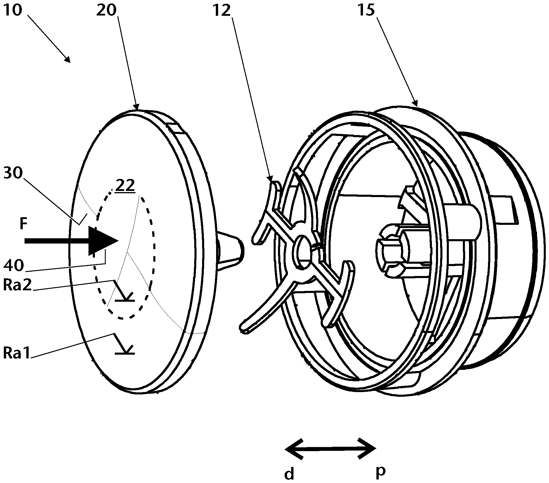
Sprechventil (10) umfassend zumindest ein Gehäuse (15) und ein Betätigungsmittel (20) zur Betätigung des Sprechventils (10), wobei das Betätigungsmittel (20) eine distale Druckfläche (22) aufweist, die eine erste Teilfläche (30) und eine zweite Teilfläche (40) umfasst, wobei die erste Teilfläche (30) eine erste mittlere Rauheit (Ra1) aufweist und die zweite Teilfläche (40) eine zweite mittlere Rauheit (Ra2) aufweist, wobei die erste mittlere Rauheit (Ra1) und die zweite mittlere Rauheit (Ra2) sich um zumindest etwa 0,1 µm unterscheiden.
Description
Die Erfindung betrifft ein Sprechventil umfassend zumindest ein Gehäuse und ein Betätigungsmittel zur Betätigung des Sprechventils.The invention relates to a speaking valve comprising at least one housing and an actuating means for actuating the speaking valve.
Sprechventile sind aus dem Stand der Technik bekannt. So zeigt die
Nachteilig an den aus dem Stand der Technik bekannten Betätigungsventilen ist, dass diese unzureichend präzise bedienbar sind. Eine außermittige Krafteinleitung, meist über den Finger des Bedieners, führt bei Sprechventilen oft zu einem Kippen und in der Folge zu einem unzureichenden Verschluss des Sprechventils. Meist wird dies von dem Benutzer durch Ausübung höheren Drucks kompensiert, was aber oftmals als unangenehm empfunden wird. Geometrische Hilfestellungen, wie beispielsweise konvexe Bereiche, beeinträchtigen das Erscheinungsbild des Sprechventils negativ. Sprechventile werden zudem in der Regel als schmucklos empfunden.A disadvantage of the actuating valves known from the prior art is that they cannot be operated with sufficient precision. An off-centre application of force, usually via the operator's finger, often leads to the speaking valves tilting and consequently to an insufficient closure of the speaking valve. This is usually compensated for by the user exerting greater pressure, which is often found to be uncomfortable. Geometrical aids, such as convex areas, adversely affect the appearance of the speaking valve. Speaking valves are also generally perceived as unadorned.
Aufgabe der Erfindung ist es daher, ein Sprechventil zur Verfügung zu stellen, das die Nachteile des Standes der Technik überkommt. Insbesondere ist die Aufgabe der Erfindung ein Sprechventil zur Verfügung zu stellen, das dem Benutzer eine präzise Betätigung des Betätigungsmittels ermöglicht.It is therefore the object of the invention to provide a speaking valve which overcomes the disadvantages of the prior art. In particular, the object of the invention is to provide a speaking valve that enables the user to actuate the actuating means precisely.
Die Aufgabe wird erfindungsgemäß gelöst mittels eines Sprechventil umfassend zumindest ein Gehäuse und ein Betätigungsmittel zur Betätigung des Sprechventils, wobei das Betätigungsmittel eine distale Druckfläche aufweist, die eine erste Teilfläche und eine zweite Teilfläche umfasst, wobei die erste Teilfläche eine erste mittlere Rauheit aufweist und die zweite Teilfläche eine zweite mittlere Rauheit aufweist, wobei die erste mittlere Rauheit und die zweite mittlere Rauheit sich um zumindest etwa 0,1 µm unterscheiden.The object is achieved according to the invention by means of a speaking valve comprising at least one housing and an actuating means for actuating the speaking valve, the actuating means having a distal pressure surface which comprises a first partial surface and a second partial surface, the first partial surface having a first average roughness and the second Partial surface has a second mean roughness, the first mean roughness and the second mean roughness differing by at least about 0.1 μm.
Weiterhin wird die Aufgabe erfindungsgemäß gelöst mittels einer Verwendung eines Betätigungsmittels eines Sprechventils mit einer distalen Druckfläche umfassend eine erste Teilfläche und eine zweite Teilfläche, wobei die erste Teilfläche eine erste mittlere Rauheit aufweist und die zweite Teilfläche eine zweite mittlere Rauheit aufweist, wobei die erste mittlere Rauheit und die zweite mittlere Rauheit sich um zumindest etwa 0,1 um unterscheiden, zur haptischen Führung bei Betätigung des Betätigungsmittels.Furthermore, the object is achieved according to the invention by using an actuating means of a speaking valve with a distal pressure surface comprising a first partial surface and a second partial surface, the first partial surface having a first average roughness and the second partial surface having a second average roughness, the first average roughness and the second average roughness differ by at least about 0.1 µm for haptic guidance upon actuation of the actuating means.
Es wird ein Sprechventil umfassend zumindest ein Gehäuse und ein Betätigungsmittel zur Betätigung des Sprechventils vorgeschlagen, wobei das Betätigungsmittel eine distale Druckfläche aufweist, die eine erste Teilfläche und eine zweite Teilfläche umfasst, wobei die erste Teilfläche eine erste mittlere Rauheit aufweist und die zweite Teilfläche eine zweite mittlere Rauheit aufweist, wobei die erste mittlere Rauheit und die zweite mittlere Rauheit sich um zumindest etwa 0,1 µm unterscheiden.A speaking valve comprising at least one housing and an actuating means for actuating the speaking valve is proposed, the actuating means having a distal pressure surface which comprises a first partial surface and a second partial surface, the first partial surface having a first average roughness and the second partial surface a second has an average roughness, the first average roughness and the second average roughness differing by at least about 0.1 μm.
Wird im Rahmen der Erfindung der Begriff „etwa“ im Zusammenhang mit Werten oder Wertebereichen verwendet, so ist darunter ein Toleranzbereich zu verstehen, den der Fachmann auf diesem Gebiet für üblich erachtet, insbesondere ist ein Toleranzbereich von ±20 %, bevorzugt ±10 %, weiter bevorzugt ±7 %, weiter bevorzugt ±6 %, weiter bevorzugt ±5 %, weiter bevorzugt ±4 % vorgesehen.If, within the scope of the invention, the term "approximately" is used in connection with values or value ranges, this is to be understood as meaning a tolerance range which the person skilled in the art in this field considers to be normal, in particular a tolerance range of ±20%, preferably ±10%, more preferably ±7%, more preferably ±6%, more preferably ±5%, more preferably ±4%.
Bei operativen Eingriffen im oberen Atemtrakt kann das Anlegen einer künstlichen Atemöffnung (Tracheostoma) in der Luftröhre notwendig sein, damit unter Umgehung von Mundraum und Kehlkopf Luft direkt in die Lunge eingeatmet werden kann. Beispielsweise bei laryngektomierten, also kehlkopflosen Personen, bei welchen der Kehlkopf operativ entfernt wurde, muss das Tracheostoma dauerhaft offengehalten und stabilisiert werden, wozu insbesondere Trachealkanülen, in der Regel aus einer Außen- und einer Innenkanüle bestehend, in das Tracheostoma eingesetzt werden. Aber auch der Einsatz so genannter „Tracheostoma-Button“ ist möglich, insbesondere für Personen, die keine Trachealkanüle mehr benötigen.In the case of surgical interventions in the upper respiratory tract, it may be necessary to create an artificial breathing opening (tracheostomy) in the trachea so that air can be inhaled directly into the lungs, bypassing the oral cavity and larynx. For example, in people who have had a laryngectomy, i.e. a person without a larynx, in whom the larynx has been surgically removed, the tracheostoma must be kept open and stabilized permanently, for which purpose tracheostomy tubes, usually consisting of an outer and an inner cannula, are inserted into the tracheostoma. But the use of so-called “tracheostoma buttons” is also possible, especially for people who no longer need a tracheostomy tube.
Des Weiteren können in das Tracheostoma auch so genannte „Shunt-Ventile“ eingesetzt werden, welche eine Wiederherstellung der Stimme ermöglichen. Schließlich können in das Tracheostoma auch Filtersysteme sowohl bei Tracheotomierten als auch bei Laryngektomierten eingesetzt werden. Derartige Filtersysteme bestehen insbesondere aus einem Pflaster mit einem eingesetzten Filter in einem Gehäuse oder aus einer üblicherweise selbstklebenden Basisplatte - in aller Regel aus Kunststoff gebildet, in welche Filter in einem Gehäuse unterschiedlichster Art einsetzbar sind.Furthermore, so-called “shunt valves” can also be inserted into the tracheostoma, which allow the voice to be restored. Finally, filter systems can also be used in the tracheostoma for both tracheostomized and laryngectomized patients. Such filter systems consist in particular of a plaster with an inserted filter in a housing or of a usually self-adhesive base plate - usually made of plastic, in which filters in a housing of the most varied types can be used.
Zu den Filtersystemen, welche für laryngo-tracheale Hilfsmittel wie Trachealkanülen, Shunt-Ventile, Tracheostoma-Button und Filtersysteme mit Pflaster oder Basisplatte eingesetzt werden, zählen die gattungsgemäßen Wärme- und Feuchtigkeitsaustauscher, auch „künstliche Nase“ genannt. Diese dienen dazu, die bei laryngektomierten und auch tracheotomierten Menschen fehlenden Regulationsmechanismen zur Erwärmung und Befeuchtung der Atemluft nachzubilden und ein In-Kontakt-Bringen der Luftröhre mit verstärkt trockener, kalter und nicht gefilterter Luft zu vermeiden. Denn durch die hierdurch hervorgerufene Reizung tritt eine erhöhte Schleimproduktion mit der nachfolgenden Gefahr der Verborkung auf. Durch Wärme- und Feuchtigkeitsaustauscher wird die eingeatmete Luft angefeuchtet, erwärmt und gleichzeitig gefiltert. Hierdurch wird die vorstehend erwähnte Borkenbildung weitgehend vermieden. Dabei hilft das regelmäßige Tragen der künstlichen Nase insbesondere bei starker Sekretabsonderung, da durch das Anfeuchten der Schleimhäute in der Luftröhre die Sekretproduktion vermindert wird.The filter systems used for laryngo-tracheal aids such as tracheal cannulas, shunt valves, tracheostoma buttons and filter systems with plasters or base plates include the generic heat and moisture exchangers, also known as “artificial noses”. These serve to simulate the regulatory mechanisms for heating and humidifying the breathing air that are missing in laryngectomy and tracheotomized people and to prevent the trachea from coming into contact with increasingly dry, cold and unfiltered air. Because the irritation caused by this leads to increased mucus production with the subsequent risk of crusting. The inhaled air is humidified, warmed and filtered at the same time by heat and moisture exchangers. This largely avoids the bark formation mentioned above. Regular wearing of the artificial nose helps, especially if there is a lot of secretion, since moistening the mucous membranes in the trachea reduces secretion production.
Wärme- und Feuchtigkeitsaustauscher für Laryngektomierte und auch Tracheotomierte weisen ein Filtermaterial auf - in aller Regel aus Papier oder Schaumstoff gebildet - durch welches die ein- und ausgeatmete Luft geleitet wird. Beim Ausatmen hält das Filtermaterial Feuchtigkeit zurück, welche dann beim Einatmen in die Luftröhre transportiert wird. Aus dem Stand der Technik bekannte Wärme- und Feuchtigkeitsaustauscher gibt es in einer großen Vielzahl unterschiedlicher Ausbildungen für unterschiedliche Adapter. Ein Universaladapter gemäß DIN EN ISO 5356-1 weist einen Durchmesser von etwa 15 mm auf, es sind jedoch aus dem Stand der Technik auch weitere Adapter mit etwa 22 mm Durchmesser bekannt.Heat and moisture exchangers for laryngectomy and tracheotomized patients have a filter material - usually made of paper or foam - through which the inhaled and exhaled air is passed. When you breathe out, the filter material retains moisture, which is then transported into the windpipe when you breathe in. Heat and moisture exchangers known from the prior art come in a large number of different configurations for different adapters. A universal adapter according to DIN EN ISO 5356-1 has a diameter of approximately 15 mm, but other adapters with a diameter of approximately 22 mm are also known from the prior art.
Ein weiteres Hilfsmittel für Laryngektomierte sind Stimmprothesen, die der Wiederherstellung der Stimme nach einer Laryngektomie dienen. Die Wiederherstellung der Stimme kann durch chirurgische Maßnahmen erfolgen. Wichtigstes Hilfsmittel dabei ist eine Stimmprothese, die auch als „Shunt-Ventil“ bezeichnet wird. Mittels der Stimmprothese können Funktionen des entfernten Kehlkopfes ersetzt werden. Zum einen wird durch den Einsatz der Stimmprothese eine Luftzufuhr von der Lunge über die Speiseröhre (Ösophagus) in den Rachen ermöglicht. Die Ausatemluft wird dabei zum Sprechen verwendet. Zum anderen dichtet die Stimmprothese die Verbindung von der Speiseröhre zur Luftröhre (Trachea) beim Schlucken von Speisen und Getränken ab, wodurch der Nutzer der Stimmprothese vor einem versehentlichen Verschlucken der Nahrung geschützt ist.Another aid for laryngectomies are voice prostheses, which are used to restore the voice after a laryngectomy. Surgical measures can be used to restore the voice. The most important tool is a voice prosthesis, also known as a "shunt valve". Using the voice prosthesis, functions of the removed larynx can be replaced. On the one hand, the use of the voice prosthesis enables air to flow from the lungs via the esophagus into the throat. The exhaled air is used for speaking. On the other hand, the voice prosthesis seals the connection between the esophagus and the windpipe (trachea) when swallowing food and drinks, which protects the user of the voice prosthesis from accidentally swallowing the food.
Sind die Wunden nach dem operativen Eingriff geheilt, können die Menschen im Normalzustand nicht sprechen. Um ein Sprechen zu ermöglichen, ist bei Verwendung einer Stimmprothese oder der noch vorhandenen Larynx bei tracheotomierten Menschen der Luftaustritt am Hals zu verschließen, damit die Luft durch die Stimmprothese beziehungsweise die Larynx geleitet wird. Hierzu werden Sprechventile verwendet.Once the wounds have healed after the surgical procedure, people cannot normally speak. In order to enable speaking, when using a voice prosthesis or the remaining larynx in people who have had a tracheostomy, the air outlet in the neck must be closed so that the air can be guided through the voice prosthesis or the larynx. Speaking valves are used for this.
Das Sprechventil kann beispielsweise eine Ventilplatte als Betätigungsmittel zur Bildung einer Ventilfunktion aufweisen. In einer weiteren Ausführungsform ist vorgesehen, dass eine Deckelplatte, die beispielsweise mit einem Ventilelement zusammenwirkt, als Betätigungsmittel dient. Auch andere Ausgestaltungen zur Bildung von Betätigungsmitteln sind aus dem Stand der Technik bekannt. Da die Einzelteile von Sprechventile meist aus dünnen Kunststoff gefertigt werden, um Gewicht zu sparen, ist es von Bedeutung, dass das Betätigungsmittel exakt bedient wird, da ansonsten Einzelteile verbogen werden und das Sprechventil nicht oder nicht vollständig schließt. Auch können Querkräfte als unangenehm an einem das Tracheostoma umgebenen Narbengewebe empfunden werden. Aus dem Stand der Technik sind geometrische Gestaltungen des Betätigungsmittels zur Führung des Benutzers bekannt, die aber das Erscheinungsbild des Sprechventils negativ beeinflussen.The speaking valve can, for example, have a valve plate as an actuating means for forming a valve function. In a further embodiment it is provided that a cover plate, which interacts with a valve element, for example, serves as the actuating means. Other configurations for forming actuating means are also known from the prior art. Since the individual parts of speaking valves are usually made of thin plastic in order to save weight, it is important that the actuating means is operated precisely, otherwise individual parts will be bent and the speaking valve will not close or will not close completely. Transverse forces can also be felt as uncomfortable on scar tissue surrounding the tracheostoma. Geometric configurations of the actuating means for guiding the user are known from the prior art, but these have a negative effect on the appearance of the speaking valve.
Vorteil an dem vorgeschlagenen Sprechventil ist, dass der Benutzer anhand unterschiedlicher Rauheitswerte der zumindest zwei Teilflächen eine Rückmeldung erhält, wo er sich mit dem Finger auf dem Betätigungsmittel befindet. Weiterhin ist von Vorteil, dass durch vorsehen unterschiedlicher Rauheitswerte der zumindest zwei Teilflächen keine optische Trennung zwischen den Teilflächen stattfindet und die Druckfläche optisch als eine einheitliche Fläche wahrgenommen werden kann.The advantage of the proposed speaking valve is that the user receives feedback based on different roughness values of the at least two partial surfaces as to where his finger is on the actuating means. Furthermore, it is advantageous that by providing different roughness values for the at least two partial surfaces, there is no optical separation between the partial surfaces and the printed surface can be perceived optically as a uniform surface.
Das Sprechventil umfasst das Betätigungsmittel, mit dem vorzugsweise mittelbar oder unmittelbar eine Ventilfunktion betätigt werden kann. Das Betätigungsmittel umfasst in einer Ausgestaltung zumindest ein Material ausgewählt aus einer Gruppe umfassend Kunststoff und/oder Metall. Kunststoffe sind für das Betätigungsmittel besonders bevorzugt. Bevorzugt ist das Betätigungsmittel gefärbt. Beispielsweise ist ein Kunststoffmaterial des Betätigungsmittels gefärbt. In einer Ausgestaltung kann mittels einer Färbung des Kunststoffmaterials ein Rauheitswert, insbesondere die erste mittlere Rauheit oder die zweite mittlere Rauheit der Druckfläche erzeugt werden. Insbesondere hat neben der Auswahl des Kunststoffes und der Ausgestaltung des Herstellungswerkzeuges die Auswahl von Additiven, die insbesondere die Farbe des Kunststoffmaterials beeinflussen, einen Einfluss auf einen Rauheitswert, insbesondere die mittlere Rauheit. In einer Ausgestaltung ist das Betätigungsmittel opak, transluzent oder transparent gefärbt. In einer weiteren Ausgestaltung ist das Betätigungsmittel einfarbig oder mehrfarbig ausgestaltet. Insbesondere kann eine Marmorierung mit zumindest zwei Farben vorgesehen sein. In einer weiteren Ausgestaltung ist vorgesehen, dass dem Kunststoffmaterial Additive zugegeben werden, die einen metallischen Effekt bringen. Solche Betätigungsmittel sind beispielsweise goldfarben, bronzefarben oder silberfarben.The speaking valve comprises the actuating means with which a valve function can be actuated, preferably directly or indirectly. In one configuration, the actuating means comprises at least one material selected from a group comprising plastic and/or metal. Plastics are particularly preferred for the actuator. The actuating means is preferably colored. For example, a plastic material of the actuating means is colored. In one embodiment, a roughness value, in particular the first average roughness or the second average roughness of the printing surface, can be generated by coloring the plastic material. In addition to the selection of the plastic and the design of the production tool, the selection of additives, in particular the color of the plastic materials affect a roughness value, especially the mean roughness. In one embodiment, the actuating means is colored opaque, translucent or transparent. In a further embodiment, the actuating means is designed in one color or in multiple colors. In particular, a marbling with at least two colors can be provided. In a further embodiment, it is provided that additives are added to the plastic material, which bring about a metallic effect. Such actuating means are, for example, gold-colored, bronze-colored or silver-colored.
Die Druckfläche ist insbesondere eine distale Fläche des Betätigungsmittels, die weiter bevorzugt von einem Rand des Gehäuses umgeben ist. In einer Ausgestaltung ist vorgesehen, dass die Druckfläche kreisrund ist. In einer weiteren Ausgestaltung ist die Druckfläche oval oder polyedrisch ausgestaltet, insbesondere rechteckig. In einer weiteren Ausgestaltung weist die Druckfläche einen konkaven und/oder konvexen Abschnitt auf. In einer weiteren Ausgestaltung ist vorgesehen, dass die erste und/oder die zweite Teilfläche zumindest teilweise konvex oder konkav ausgestaltet sind. Insbesondere ist ein mittlerer Flächenabschnitt der Druckfläche konvex oder konkav ausgestaltet.The pressure surface is in particular a distal surface of the actuating means, which is more preferably surrounded by an edge of the housing. In one embodiment it is provided that the pressure surface is circular. In a further embodiment, the pressure surface is designed to be oval or polyhedral, in particular rectangular. In a further embodiment, the pressure surface has a concave and/or convex section. In a further embodiment it is provided that the first and/or the second partial surface are at least partially convex or concave. In particular, a central surface section of the pressure surface is convex or concave.
Weiter bevorzugt ist in einer Ausgestaltung vorgesehen, dass die erste Teilfläche ein randseitiger Flächenabschnitt der Druckfläche ist. Insbesondere ist die erste Teilfläche eine umlaufende Randseitige, weiter bevorzugt ringförmige Fläche, beispielsweise ein Kreisring, ein ovaler Ring oder ein an die äußere Form der Druckfläche angepasster Ring. Insbesondere umgibt die erste Teilfläche die zweite Teilfläche. In einer weiteren Ausgestaltung ist vorgesehen, dass die erste Teilfläche ein mittlerer Flächenabschnitt der Druckfläche ist. Insbesondere ist die erste Teilfläche von der zweiten Teilfläche umgeben. Bevorzugt ist vorgesehen, dass die erste Teilfläche derart angeordnet ist, dass auf diese eine Betätigungskraft ausübbar ist. Insbesondere ist die erste Teilfläche kreisrund, oval oder formähnlich zur Druckfläche ausgestaltet.In a further preferred embodiment, it is provided that the first partial surface is a surface section on the edge of the pressure surface. In particular, the first partial surface is a peripheral, more preferably ring-shaped surface, for example a circular ring, an oval ring or a ring adapted to the outer shape of the pressure surface. In particular, the first partial area surrounds the second partial area. In a further embodiment it is provided that the first partial area is a middle area section of the pressure area. In particular, the first partial area is surrounded by the second partial area. Provision is preferably made for the first partial surface to be arranged in such a way that an actuating force can be exerted on it. In particular, the first partial surface is designed to be circular, oval or similar in shape to the pressure surface.
In einer weiteren Ausgestaltung ist vorgesehen, dass die erste Teilfläche eine erste mittlere Rauheit Ra1 aufweist. Bevorzugt ist die mittlere Rauheit Ra1 etwa 1,4 µm bis etwa 5 µm, bevorzugt etwa 1,5 µm bis etwa 2 µm. In einer Ausgestaltung ist vorgesehen, dass die erste Teilfläche eine erste gemittelte Rautiefe Rz1 aufweist. Insbesondere ist die erste gemittelte Rautiefe Rz1 etwa 7 µm bis etwa 20 µm, bevorzugt etwa 7 µm bis etwa 15 µm, weiter bevorzugt etwa 8 µm bis etwa 11 µm.In a further embodiment it is provided that the first partial surface has a first mean roughness R a 1 . The average roughness R a 1 is preferably about 1.4 μm to about 5 μm, preferably about 1.5 μm to about 2 μm. In one configuration, it is provided that the first partial area has a first average peak-to-valley height R z 1 . In particular, the first average peak-to-valley height R z 1 is about 7 μm to about 20 μm, preferably about 7 μm to about 15 μm, more preferably about 8 μm to about 11 μm.
In einer weiteren Ausgestaltung ist vorgesehen, dass die zweite Teilfläche eine Betätigungsfläche ist. Bevorzugt ist vorgesehen, dass die zweite Teilfläche derart angeordnet ist, dass auf diese eine Betätigungskraft ausübbar ist. In einer weiteren Ausgestaltung ist vorgesehen, dass die zweite Teilfläche ein mittlerer Flächenabschnitt der Druckfläche ist. Insbesondere ist die zweite Teilfläche von der ersten Teilfläche umgeben. Insbesondere ist die zweite Teilfläche kreisrund, oval oder formähnlich zur Druckfläche ausgestaltet. In einer weiteren Ausgestaltung ist vorgesehen, dass die zweite Teilfläche ein randseitiger Flächenabschnitt der Druckfläche ist. Insbesondere ist die zweite Teilfläche eine umlaufende Randseitige, weiter bevorzugt ringförmige Fläche, beispielsweise ein Kreisring, ein ovaler Ring oder ein an die äußere Form der Druckfläche angepasster Ring. Insbesondere umgibt die zweite Teilfläche die erste Teilfläche.In a further embodiment it is provided that the second partial surface is an actuating surface. Provision is preferably made for the second partial surface to be arranged in such a way that an actuating force can be exerted on it. In a further embodiment it is provided that the second partial area is a middle area section of the pressure area. In particular, the second partial area is surrounded by the first partial area. In particular, the second partial surface is designed to be circular, oval or similar in shape to the pressure surface. In a further embodiment, it is provided that the second partial surface is a surface section on the edge of the pressure surface. In particular, the second partial surface is a peripheral, more preferably ring-shaped surface, for example a circular ring, an oval ring or a ring adapted to the outer shape of the pressure surface. In particular, the second partial area surrounds the first partial area.
In einer weiteren Ausgestaltung weist die zweite Teilfläche eine zweite mittlere Rauheit Ra2 auf. Insbesondere ist die zweite mittlere Rauheit Ra2 etwa 1,4 µm bis etwa 5 µm, bevorzugt etwa 1,5 µm bis etwa 2 µm. Erfindungsgemäß unterscheidet sich die erste mittlere Rauheit Ra1 von der zweiten mittleren Rauheit Ra2. Bevorzugt weist der Betrag |ΔRa| der Differenz von Ra1 und Ra2 zumindest etwa 0,1 µm auf. Weiter bevorzugt ist |ΔRa| größer etwa 0,1 µm, weiter bevorzugt ist |ΔRa| größer etwa 0,2 µm, weiter bevorzugt ist |ΔRa| größer etwa 0,3 µm, weiter bevorzugt ist |ΔRa| zwischen etwa 0,1 µm und etwa 5 µm, weiter bevorzugt zwischen etwa 0,1 µm und etwa 1 µm, weiter bevorzugt zwischen etwa 0,1 µm und etwa 0,5 µm, weiter bevorzugt zwischen etwa 0,2 µm und etwa 0,5 µm, weiter bevorzugt zwischen etwa 0,3 µm und 0,5 µm, weiter bevorzugt zwischen etwa 0,4 µm und etwa 0,5 µm.In a further configuration, the second partial surface has a second mean roughness R a 2 . In particular, the second average roughness R a 2 is about 1.4 μm to about 5 μm, preferably about 1.5 μm to about 2 μm. According to the invention , the first mean roughness R a 1 differs from the second mean roughness R a 2 the difference between R a 1 and R a 2 is at least about 0.1 µm. More preferably |ΔR a | greater than about 0.1 μm, more preferably |ΔR a | greater than about 0.2 μm, more preferably |ΔR a | greater than about 0.3 μm, more preferably |ΔR a | between about 0.1 µm and about 5 µm, more preferably between about 0.1 µm and about 1 µm, more preferably between about 0.1 µm and about 0.5 µm, more preferably between about 0.2 µm and about 0 .5 µm, more preferably between about 0.3 µm and 0.5 µm, more preferably between about 0.4 µm and about 0.5 µm.
Die neurologischen und biomechanischen Prozesse, auf denen eine haptische Wahrnehmung beruht, sind äußerst komplex. Feine Oberflächentexturen, wie beispielsweise eine Rauheit können nicht durch Berührung mit statischem Druck der Fingerspitzen wahrgenommen werden, sondern nur mittels dynamischer Untersuchung, wobei die Fingerspitzen über eine Oberfläche streichen und die Haut der Fingerspitzen über die Zeit unterschiedlich mechanisch verformt wird. Diese dynamischen Hautverformungen werden von den in der Epidermis und Dermis eingebetteten und auf mechanische Einwirkung ansprechenden Nervenzellen in transiente Signale umgewandelt und zum zentralen Nervensystem geleitet, um dort analysiert zu werden. Basierend auf der Analyse der transienten Signale wird die Oberflächentextur vom zentralen Nervensystem eingeordnet. Die Finger, die können sehr feine Strukturen wahrnehmen und schon unterschiedliche Rauigkeiten von unter etwa 0,1 µm voneinander unterscheiden. Die vorliegende Erfindung hat daher den Vorteil, dass die Druckfläche in haptisch unterschiedliche Teilbereiche unterteilt werden kann und der Benutzer optimal geführt wird, denjenigen Teilbereich zu drücken, der einen optimalen Verschluss des Sprechventils ergibt und gleichzeitig als angenehm empfunden wird.The neurological and biomechanical processes on which haptic perception is based are extremely complex. Fine surface textures, such as roughness, cannot be perceived by touch with static pressure of the fingertips, but only by dynamic examination, where the fingertips sweep over a surface and the skin of the fingertips is mechanically deformed differently over time. These dynamic skin deformations are converted into transient signals by the mechanically responsive neurons embedded in the epidermis and dermis and transmitted to the central nervous system for analysis. Based on the analysis of the transient signals, the surface texture is classified by the central nervous system. The fingers can perceive very fine structures and distinguish different roughnesses of less than about 0.1 µm from each other. The present invention therefore has the advantage that the pressure surface can be divided into haptically different sub-areas and the user is optimally guided to press that sub-area that results in an optimal closure of the speaking valve and is at the same time perceived as pleasant.
In einer weiteren Ausgestaltung weist die zweite Teilfläche eine zweite gemittelte Rautiefe Rz2 auf. Bevorzugt ist die zweite gemittelte Rautiefe Rz2 etwa 7 µm bis etwa 20 µm, weiter bevorzugt etwa 7 µm bis etwa 15 µm, weiter bevorzugt etwa 8 µm bis etwa 11 µm.In a further configuration, the second partial area has a second average peak-to-valley height R z 2 . The second mean peak-to-valley height R z 2 is preferably about 7 μm to about 20 μm, more preferably about 7 μm to about 15 μm, more preferably about 8 μm to about 11 μm.
In einer Ausgestaltung unterscheidet sich die erste gemittelte Rautiefe Rz1 von der zweiten gemittelten Rautiefe Rz2. Bevorzugt unterscheidet sich sowohl die mittleren Rauheiten Ra1 und Ra2 und die gemittelten Rautiefen Rz1 und Rz2 voneinander. Bevorzugt weist der Betrag |ΔRz| der Differenz von Rz1 und Rz2 zumindest etwa 0,3 µm auf. In einer weiteren Ausgestaltung ist vorgesehen, dass |ΔRz| größer etwa 0,3 µm ist, weiter bevorzugt ist |ΔRz| größer etwa 0,4 µm, weiter bevorzugt ist |ΔRz| größer etwa 0,5 µm, weiter bevorzugt ist |ΔRz| zwischen etwa 0,4 µm und etwa 10 µm, weiter bevorzugt zwischen etwa 0,4 µm und etwa 5 µm, weiter bevorzugt zwischen etwa 0,4 µm und etwa 3 µm, weiter bevorzugt zwischen etwa 0,5 µm und etwa 0,3 µm.In one embodiment, the first mean roughness depth R z 1 differs from the second mean roughness depth R z 2 . The mean roughnesses R a 1 and R a 2 and the mean roughness depths R z 1 and R z 2 preferably differ from one another. The amount |ΔR z | the difference between R z 1 and R z 2 is at least about 0.3 µm. In a further refinement, it is provided that |ΔR z | is greater than about 0.3 µm, more preferably |ΔR z | greater than about 0.4 μm, more preferably |ΔR z | greater than about 0.5 μm, more preferably |ΔR z | between about 0.4 µm and about 10 µm, more preferably between about 0.4 µm and about 5 µm, more preferably between about 0.4 µm and about 3 µm, more preferably between about 0.5 µm and about 0.3 µm µm.
In einer Ausgestaltung ist vorgesehen, dass die erste Teilfläche und/oder die zweite Teilfläche einen Lack, beispielsweise ein Haptiklack, einen Aufkleber, beispielsweise einen bedruckten Aufkleber, oder ein sich von der jeweils anderen Teilfläche unterscheidendes Oberflächenmaterial aufweist. Wenn beispielsweise eine kleine Differenz der Rauheitswerte |ΔRa| und/oder |ΔRz| gewählt wird, beispielsweise |ΔRa| bis etwa 0,4 µm und/oder |ΔRz| bis etwa 2,5 µm, wird kein oder kaum ein optischer Unterscheid insbesondere in Bezug auf eine Mattheit der Oberfläche wahrgenommen. Die Betätigungsfläche wirkt einheitlich und ist nur durch haptische Unterschiede in Teilflächen aufgeteilt. In einer Ausgestaltung können sich die erste Teilfläche und die zweite Teilfläche optisch unterscheiden, beispielsweise durch insbesondere zusätzliches Aufbringen eines Logos oder eines Musters auf die erste Teilfläche oder die zweite Teilfläche.In one embodiment it is provided that the first partial surface and/or the second partial surface has a lacquer, for example a haptic lacquer, a sticker, for example a printed sticker, or a surface material that differs from the respective other partial surface. For example, if a small difference in roughness values |ΔR a | and/or |ΔR z | is chosen, for example |ΔR a | to about 0.4 µm and/or |ΔR z | up to about 2.5 µm, no or hardly any optical difference is perceived, in particular with regard to a dullness of the surface. The actuating surface looks uniform and is only divided into sub-areas due to haptic differences. In one configuration, the first partial area and the second partial area can differ optically, for example by the additional application of a logo or a pattern to the first partial area or the second partial area.
Bevorzugt ist eine Rauheitsmessung nach DIN EN ISO 4287 (2010-07) beziehungsweise DIN EN ISO 4288 (1998-04) / SOP 4-Tastschnitt 1 Rev. 4 durchgeführt, um die im Rahmen der Erfindung genannten Werte zu erhalten. Insbesondere sind folgenden Parameter für die Messung verwendet:
- ◯ Messgerät: MarSurf XCR20
- ◯ Messsoftware: MarWin 9.00-23
- ◯ Messtaster: BFW A 10-45-2/90°
- ◯ Vorschubeinheit: MarSurf GD26
- ◯ Messbereich: ± 250 µm
- ◯ Taststrecke: 5,6 mm
- ◯ Gesamtmessstrecke: 4,0 mm
- ◯ Wellenfilter: 0,8 mm
- ◯ Tastspitzenradius: 2 µm
- ◯ Tastkraft: 0,7 mN
- ◯ Betriebsart: Freiabtastung
- ◯ Anz. Einzelmessungen: 5 / Probe
- ◯ Measuring device: MarSurf XCR20
- ◯ Measurement software: MarWin 9.00-23
- ◯ Probe: BFW A 10-45-2/90°
- ◯ Feed unit: MarSurf GD26
- ◯ Measuring range: ± 250 µm
- ◯ Tracing distance: 5.6 mm
- ◯ Total measuring distance: 4.0 mm
- ◯ Wave filter: 0.8mm
- ◯ Probe tip radius: 2 µm
- ◯ Tracing force: 0.7 mN
- ◯ Operating mode: free scanning
- ◯ no. Individual measurements: 5 / sample
Weiter bevorzugt wird je Probe ein willkürlich gewähltes Segment über einen Winkelbereich von etwa 50° bis etwa 60° mit 5 Einzelmessungen vermessen. Insbesondere erfolgt bei Proben mit einem Aufkleber die Messung vollständig auf dem Aufkleber. Weiter bevorzugt werden optisch auffällige Bereiche sowie Bereiche beispielsweise von teilweise Ablösungen des Aufklebers von den Messzonen ausgeschlossen. Bevorzugt ist ein Abstand zwischen 2 Einzelmessungen jeweils zwischen etwa 10° und etwa 15°. Bevorzugt verläuft die Tastrichtung der Einzelmessungen, bezogen auf die Probenoberfläche, von innen nach außen.More preferably, an arbitrarily selected segment is measured over an angular range of about 50° to about 60° with 5 individual measurements for each sample. In particular, in the case of samples with a sticker, the measurement is carried out entirely on the sticker. More preferably, optically conspicuous areas and areas, for example where the label has partially come off, are excluded from the measuring zones. A distance between 2 individual measurements of between about 10° and about 15° is preferred. The scanning direction of the individual measurements, based on the sample surface, preferably runs from the inside to the outside.
In einer ersten beispielhaften Ausgestaltungen ist vorgesehen, dass eine erste Teilfläche einer Druckfläche eine Kunststoffoberfläche mit einer metallischen Farbe ist. Weiterhin ist eine beispielhafte zweite Teilfläche mit einem Aufkleber beklebt, der beispielhaft ein aufgedrucktes Ornament aufweist. In der ersten beispielhaften Ausgestaltung weisen die Teilflächen eine Differenz der mittleren Rauheit |ΔRa| von etwa 0,4 µm auf. Weiterhin weisen die Teilflächen eine Differenz der gemittelten Rautiefe |ΔRz| von etwa 5,6 µm auf. Mit dem oben aufgeführten Verfahren nach DIN EN ISO 4287 kann des Weiteren festgestellt werden, dass eine Differenz der gemittelten größten Profilspitze |ΔRp| der Teilflächen von etwa 1,9 µm vorliegt. Weiterhin ist eine Differenz der gemittelten Tiefe des größten Profiltales |ΔRv| etwa 0,6 µm.In a first exemplary configuration, it is provided that a first partial area of a printing area is a plastic surface with a metallic color. Furthermore, an exemplary second partial surface is covered with a sticker that has an ornament printed on it, for example. In the first exemplary embodiment, the partial areas have a difference in average roughness |ΔR a | of about 0.4 µm on. Furthermore, the partial areas have a difference in the mean peak-to-valley height |ΔR z | of about 5.6 µm. With the method listed above according to DIN EN ISO 4287, it can also be determined that a difference in the averaged largest profile peak |ΔR p | of the sub-areas of about 1.9 µm. Furthermore, a difference in the average depth of the largest profile valley |ΔR v | about 0.6 µm.
In einer zweiten beispielhaften Ausgestaltungen ist vorgesehen, dass eine erste Teilfläche einer Druckfläche eine Kunststoffoberfläche mit einer opaken türkisenen Farbe ist. Weiterhin ist eine beispielhafte zweite Teilfläche mit einem Aufkleber beklebt, der beispielhaft eine aufgedruckte Blume aufweist. In der zweiten beispielhaften Ausgestaltung weisen die Teilflächen eine Differenz der mittleren Rauheit |ΔRa| von etwa 0,3 µm auf. Weiterhin weisen die Teilflächen eine Differenz der gemittelten Rautiefe |ΔRz| von etwa 0,3 µm auf. Mit dem oben aufgeführten Verfahren nach DIN EN ISO 4287 kann des Weiteren festgestellt werden, dass eine Differenz der gemittelten größten Profilspitze |ΔRp| der Teilflächen von etwa 1,4 µm vorliegt. Weiterhin ist eine Differenz der gemittelten Tiefe des größten Profiltales |ΔRv| etwa 1,2 µm.In a second exemplary configuration, it is provided that a first partial area of a printing area is a plastic surface with an opaque turquoise color. Furthermore, an example of a second partial area is covered with a sticker that has a flower printed on it, for example. In the second exemplary embodiment, the partial areas have a difference in average roughness |ΔR a | of about 0.3 µm. Furthermore, the partial areas have a difference in the mean peak-to-valley height |ΔR z | of about 0.3 µm. With the method listed above according to DIN EN ISO 4287, it can also be determined that a difference in the averaged largest profile peak |ΔR p | of the sub-areas of about 1.4 µm. Furthermore, a difference in the average depth of the largest profile valley |ΔR v | about 1.2 µm.
Eine beispielhafte Tabelle von Messergebnissen einer Messung nach DIN EN ISO 4287 mit den oben Aufgeführten Parametern, insbesondere gemittelt nach fünf Messdurchgängen an unterschiedlichen Stellen der Druckfläche beziehungsweise der jeweils gemessenen Teilfläche ist im Folgenden dargestellt:
Das Gehäuse umfasst in einer Ausgestaltung zumindest ein Gehäusematerial ausgewählt aus einer Gruppe umfassend Kunststoff oder Metall. Kunststoffe sind für das Gehäuse besonders bevorzugt. Bevorzugt ist das Gehäuse gefärbt. Beispielsweise ist ein Kunststoffmaterial des Gehäuses gefärbt. In einer Ausgestaltung ist das Gehäuse opak, transluzent oder transparent gefärbt. In einer weiteren Ausgestaltung ist das Gehäuse einfarbig oder mehrfarbig ausgestaltet. Insbesondere kann eine Marmorierung mit zumindest zwei Farben vorgesehen sein. In einer weiteren Ausgestaltung ist vorgesehen, dass dem Kunststoffmaterial des Gehäuses Additive zugegeben werden, die einen metallischen Effekt bringen. Solche Gehäuse sind beispielsweise goldfarben, bronzefarben oder silberfarben. In einer Ausgestaltung unterscheiden sich Material und/oder die Farben von Gehäuse und Betätigungsmittel. In einer weiteren Ausgestaltung sind Gehäuse und Betätigungsmittel im Wesentlichen gleich gefärbt. Durch unterschiedliche Kombinationen von Farben oder Materialien lassen sich vorteilhafter Weise Sprechventile optisch ansprechend gestalten.In one configuration, the housing comprises at least one housing material selected from a group comprising plastic or metal. Plastics are particularly preferred for the housing. The housing is preferably colored. For example, a plastic material of the housing is colored. In one configuration, the housing is colored opaque, translucent or transparent. In a further embodiment, the housing is designed in one color or in multiple colors. In particular, a marbling with at least two colors can be provided. In a further embodiment it is provided that additives are added to the plastic material of the housing, which bring about a metallic effect. Such housings are, for example, gold-colored, bronze-colored or silver-colored. In one embodiment, the material and/or the colors of the housing and actuating means differ. In a further embodiment, the housing and the actuating means are colored essentially the same. Speaking valves can advantageously be made visually appealing by different combinations of colors or materials.
Der Begriff „im Wesentlichen“ gibt einen Toleranzbereich an, der für den Fachmann unter wirtschaftlichen und technischen Gesichtspunkten zu vertreten ist, sodass das entsprechende Merkmal noch als solches zu erkennen oder verwirklicht ist.The term "essentially" indicates a tolerance range that is acceptable for the person skilled in the art from an economic and technical point of view, so that the corresponding feature can still be recognized as such or implemented.
Weiterhin wird eine Verwendung eines Betätigungsmittels eines Sprechventils mit einer distalen Druckfläche umfassend eine erste Teilfläche und eine zweite Teilfläche vorgeschlagen, wobei die erste Teilfläche eine erste mittlere Rauheit aufweist und die zweite Teilfläche eine zweite mittlere Rauheit aufweist, wobei die erste mittlere Rauheit und die zweite mittlere Rauheit sich um zumindest etwa 0,1 µm unterscheiden, zur haptischen Führung bei Betätigung des Betätigungsmittels in einem Sprechventil.Furthermore, the use of an actuating means of a speaking valve with a distal pressure surface comprising a first partial surface and a second partial surface is proposed, the first partial surface having a first average roughness and the second partial surface having a second average roughness, the first average roughness and the second average Roughness differ by at least about 0.1 microns, for haptic guidance when actuating the actuating means in a speaking valve.
Weitere vorteilhafte Ausgestaltungen gehen aus der nachfolgenden Zeichnung hervor. Die dort dargestellte Weiterbildung ist jedoch nicht beschränkend auszulegen, vielmehr können die dort beschriebenen Merkmale untereinander und mit den oben beschriebenen Merkmalen zu weiteren Ausgestaltungen kombiniert werden. Des Weiteren sei darauf verwiesen, dass die in der Figurenbeschreibung angegebenen Bezugszeichen den Schutzbereich der vorliegenden Erfindung nicht beschränken, sondern lediglich auf die in den Figuren gezeigten Ausführungsbeispiele verweisen. Es zeigt
-
1 ein Sprechventil in einer Explosionsansicht.
-
1 a speaking valve in an exploded view.
Das Betätigungsmittel 20 weist distal d eine Druckfläche 22 auf, die unterteilt ist in eine erste Teilfläche 30 und eine zweite Teilfläche 40, die in der
Vorteilhafterweise kann mittels des Sprechventils 10 eine haptische Führung eines Benutzers für die korrekte Fingerposition auf dem Betätigungsmittel 20 erfolgen, ohne dass ein optischer Eindruck des Sprechventils gestört wird.Advantageously, the speaking
Claims (6)
Priority Applications (5)
| Application Number | Priority Date | Filing Date | Title |
|---|---|---|---|
| DE102019111596.5A DE102019111596B4 (en) | 2019-05-06 | 2019-05-06 | speaking valve |
| US17/603,801 US12303644B2 (en) | 2019-05-06 | 2020-04-05 | Speaking valve |
| EP20724781.8A EP3833417B1 (en) | 2019-05-06 | 2020-05-04 | Speaking valve |
| CN202080014709.0A CN113507955B (en) | 2019-05-06 | 2020-05-04 | speaking valve |
| PCT/EP2020/062318 WO2020225212A1 (en) | 2019-05-06 | 2020-05-04 | Speaking valve |
Applications Claiming Priority (1)
| Application Number | Priority Date | Filing Date | Title |
|---|---|---|---|
| DE102019111596.5A DE102019111596B4 (en) | 2019-05-06 | 2019-05-06 | speaking valve |
Publications (2)
| Publication Number | Publication Date |
|---|---|
| DE102019111596A1 DE102019111596A1 (en) | 2020-11-12 |
| DE102019111596B4 true DE102019111596B4 (en) | 2022-07-28 |
Family
ID=70617093
Family Applications (1)
| Application Number | Title | Priority Date | Filing Date |
|---|---|---|---|
| DE102019111596.5A Expired - Fee Related DE102019111596B4 (en) | 2019-05-06 | 2019-05-06 | speaking valve |
Country Status (5)
| Country | Link |
|---|---|
| US (1) | US12303644B2 (en) |
| EP (1) | EP3833417B1 (en) |
| CN (1) | CN113507955B (en) |
| DE (1) | DE102019111596B4 (en) |
| WO (1) | WO2020225212A1 (en) |
Citations (2)
| Publication number | Priority date | Publication date | Assignee | Title |
|---|---|---|---|---|
| DE102012024817A1 (en) | 2012-12-19 | 2014-06-26 | Andreas Fahl Medizintechnik-Vertrieb Gmbh | speaking valve |
| DE102013018423A1 (en) | 2013-11-04 | 2015-05-07 | Andreas Fahl Medizintechnik-Vertrieb Gmbh | Speech valve for laryngectomy or tracheotomy |
Family Cites Families (39)
| Publication number | Priority date | Publication date | Assignee | Title |
|---|---|---|---|---|
| CA1340219C (en) * | 1988-04-06 | 1998-12-15 | Tadahiko Katsura | Labelled vessel and process for preparation thereof |
| US5779482A (en) * | 1994-01-12 | 1998-07-14 | Yuugenkaisha Mediamews | Indications for the visually handicapped using transparent three-dimensional ink |
| JP3501417B2 (en) * | 1994-09-26 | 2004-03-02 | 株式会社ブリヂストン | Information display method for rubber vulcanized molded products |
| US6090483A (en) * | 1997-01-17 | 2000-07-18 | Nitto Denko Corporation | Adhesive sheet for printing and label |
| SE512029C2 (en) * | 1998-05-14 | 2000-01-17 | Atos Medical Ab | Speech valve with filter |
| SE514362C2 (en) * | 1999-06-04 | 2001-02-12 | Atos Medical Ab | Vocal valve |
| US6596384B1 (en) * | 2002-04-09 | 2003-07-22 | International Business Machines Corporation | Selectively roughening conductors for high frequency printed wiring boards |
| US7370654B2 (en) * | 2002-11-13 | 2008-05-13 | Atos Medical Ab | Tracheostoma valve |
| DE10326298B4 (en) * | 2003-06-11 | 2008-03-20 | Avery Dennison Zweckform Office Products Europe Gmbh | label sheet |
| US20050270963A1 (en) * | 2004-06-04 | 2005-12-08 | Tdk Corporation | Optical recording medium |
| WO2006024253A1 (en) * | 2004-09-03 | 2006-03-09 | Weinmann Geräte für Medizin GmbH & Co. KG | Plastics for medical technical devices |
| US20080145532A1 (en) * | 2006-12-15 | 2008-06-19 | Mcdonald Duane Lyle | Method of making tactile features on cartons |
| JP2009029345A (en) * | 2007-07-30 | 2009-02-12 | Shimano Inc | Brake for bicycle, and gearshift operating device |
| GB2457949B (en) * | 2008-02-29 | 2010-05-12 | Rue De Int Ltd | Security documents |
| JP4695665B2 (en) * | 2008-03-31 | 2011-06-08 | 株式会社村上開明堂 | Rearview mirror with light emitting display |
| ATE555893T1 (en) * | 2008-05-28 | 2012-05-15 | Avery Dennison Corp | BIAXIALLY STRETCHED MULTILAYER FILM AND ASSOCIATED LABEL AND METHOD |
| US8991394B2 (en) * | 2008-11-28 | 2015-03-31 | Atos Medical Ab | Breathing protector |
| US8377316B2 (en) * | 2009-04-30 | 2013-02-19 | Xerox Corporation | Structure and method for creating surface texture of compliant coatings on piezo ink jet imaging drums |
| DE102010048317B4 (en) * | 2010-10-14 | 2016-01-07 | Primed Halberstadt Medizintechnik Gmbh | Artificial nose with speaking valve |
| EP2794263B2 (en) * | 2011-09-07 | 2022-12-28 | Jindal Films Europe Virton SPRL | Pressure-sensitive label structures, and methods of making same |
| US8672680B2 (en) * | 2011-12-03 | 2014-03-18 | Dmitry BAKLANOV | Tactile relief films, decals and stickers for indicating object characteristics |
| ES2534819T3 (en) * | 2012-06-11 | 2015-04-29 | Sicpa Holding Sa | Methods for printing touch security badges |
| MX2015000119A (en) * | 2012-06-25 | 2015-04-14 | Ross Technology Corp | ELASTOMERIC COATINGS WITH HYDROPHOBIC AND / OR OLEOPHOBIC PROPERTIES. |
| JP2014026235A (en) * | 2012-07-30 | 2014-02-06 | Seiko Instruments Inc | Adhesive label and label issuance apparatus |
| DE102012109916A1 (en) * | 2012-10-17 | 2014-04-17 | Tracoe Medical Gmbh | speaking valve |
| US20140150779A1 (en) * | 2012-12-05 | 2014-06-05 | Jan-Ove Persson | Breathing protector |
| JP2014159514A (en) * | 2013-02-19 | 2014-09-04 | Seiko Instruments Inc | Adhesive label, manufacturing method of adhesive label, and label issuance device |
| JP2014159515A (en) * | 2013-02-19 | 2014-09-04 | Seiko Instruments Inc | Adhesive label, manufacturing method of adhesive label, and label issuance device |
| US9259953B2 (en) * | 2013-09-27 | 2016-02-16 | Eastman Kodak Company | Tactile images having coefficient of friction differences |
| CN203577093U (en) * | 2013-11-12 | 2014-05-07 | 王洪泉 | Speaking valve with gas delivery pipe support |
| DE102014002063A1 (en) * | 2014-02-18 | 2015-08-20 | Andreas Fahl Medizintechnik-Vertrieb Gmbh | Speech valve with at least partially formed of an elastic material cover part |
| JP6421019B2 (en) * | 2014-04-24 | 2018-11-07 | 日東電工株式会社 | Laminated sheet |
| KR20160148609A (en) * | 2014-04-24 | 2016-12-26 | 닛토덴코 가부시키가이샤 | Pressure-sensitive adhesive sheet |
| JP6664167B2 (en) * | 2014-11-28 | 2020-03-13 | 日東電工株式会社 | Adhesive sheet |
| FI3237480T4 (en) * | 2014-12-23 | 2022-12-30 | Aqueous coating composition with soft touch upon drying | |
| JP6774779B2 (en) * | 2016-05-02 | 2020-10-28 | 日東電工株式会社 | Adhesive sheet with release liner |
| EP3483868A4 (en) * | 2016-07-08 | 2020-03-18 | Yupo Corporation | ELECTROSTATIC ADSORPTION MULTILAYER SHEET AND DISPLAY DEVICE |
| DE102017130662B4 (en) * | 2017-12-20 | 2019-08-14 | Andreas Fahl Medizintechnik-Vertrieb Gmbh | Heat and moisture exchanger |
| US11691912B2 (en) * | 2018-12-18 | 2023-07-04 | Apple Inc. | Chemically strengthened and textured glass housing member |
-
2019
- 2019-05-06 DE DE102019111596.5A patent/DE102019111596B4/en not_active Expired - Fee Related
-
2020
- 2020-04-05 US US17/603,801 patent/US12303644B2/en active Active
- 2020-05-04 WO PCT/EP2020/062318 patent/WO2020225212A1/en not_active Ceased
- 2020-05-04 CN CN202080014709.0A patent/CN113507955B/en active Active
- 2020-05-04 EP EP20724781.8A patent/EP3833417B1/en active Active
Patent Citations (2)
| Publication number | Priority date | Publication date | Assignee | Title |
|---|---|---|---|---|
| DE102012024817A1 (en) | 2012-12-19 | 2014-06-26 | Andreas Fahl Medizintechnik-Vertrieb Gmbh | speaking valve |
| DE102013018423A1 (en) | 2013-11-04 | 2015-05-07 | Andreas Fahl Medizintechnik-Vertrieb Gmbh | Speech valve for laryngectomy or tracheotomy |
Also Published As
| Publication number | Publication date |
|---|---|
| EP3833417B1 (en) | 2021-12-15 |
| CN113507955B (en) | 2022-07-19 |
| DE102019111596A1 (en) | 2020-11-12 |
| WO2020225212A1 (en) | 2020-11-12 |
| US20220193355A1 (en) | 2022-06-23 |
| CN113507955A (en) | 2021-10-15 |
| EP3833417A1 (en) | 2021-06-16 |
| US12303644B2 (en) | 2025-05-20 |
Similar Documents
| Publication | Publication Date | Title |
|---|---|---|
| DE2427196C2 (en) | Multi-layer bandage for laryngectomized patients | |
| DE60316622T2 (en) | face mask | |
| EP2054114B1 (en) | Individually adapted breathing mask | |
| DE10322964B4 (en) | Control unit for anti-snoring device and anti-snoring device | |
| EP3065802B1 (en) | Speech valve for persons having undergone a laryngectomy or tracheotomy | |
| DE19706963A1 (en) | Tracheostoma filter assembly | |
| EP3861932A1 (en) | Method and device for determining regional compliance of a lung in spontaneous breathing | |
| WO2015067234A2 (en) | Set for adhesively attaching over a tracheostoma of a laryngectomized patient | |
| DE102014018678B4 (en) | Tracheostoma protection | |
| DE102019111596B4 (en) | speaking valve | |
| DE3490002T1 (en) | Ventilator | |
| DE202012004539U1 (en) | Moist heat exchanger for the breathing air | |
| DE102012024817A1 (en) | speaking valve | |
| DE202011003781U1 (en) | Respiratory device with a holder and a regenerative heat-moisture exchanger | |
| DE202017001233U1 (en) | Face and breathing bowl | |
| EP1747792B1 (en) | Heat and moisture exchanger with speaking function | |
| HK40055653A (en) | Speaking valve | |
| DE3871545T2 (en) | VOICE TRAINING VALVE FOR LARYN GEKTOMY PATIENTS. | |
| DE102020114684A1 (en) | Tracheostomy epithesis and method for producing a tracheostomy epithesis | |
| EP3302662B1 (en) | Arrangement having a gas flow reversing element and a switchable connection | |
| DE202008014098U1 (en) | compress | |
| DE10301149B4 (en) | Procedures for adjusting respiratory masks and using a kit to perform them | |
| EP3888481A1 (en) | Method of manufacturing a user-individual face mask | |
| DE202009000521U1 (en) | Compressor for tracheostomy tubes | |
| DE102015221526A1 (en) | breathing mask |
Legal Events
| Date | Code | Title | Description |
|---|---|---|---|
| R012 | Request for examination validly filed | ||
| R016 | Response to examination communication | ||
| R018 | Grant decision by examination section/examining division | ||
| R020 | Patent grant now final | ||
| R119 | Application deemed withdrawn, or ip right lapsed, due to non-payment of renewal fee |