[go: up one dir, main page]

DE102019100756A1 - Device for treating a web - Google Patents

Device for treating a web Download PDF

Info

Publication number
DE102019100756A1
DE102019100756A1 DE102019100756.9A DE102019100756A DE102019100756A1 DE 102019100756 A1 DE102019100756 A1 DE 102019100756A1 DE 102019100756 A DE102019100756 A DE 102019100756A DE 102019100756 A1 DE102019100756 A1 DE 102019100756A1
Authority
DE
Germany
Prior art keywords
web
sealing
treatment chamber
slot
segments
Prior art date
Legal status (The legal status is an assumption and is not a legal conclusion. Google has not performed a legal analysis and makes no representation as to the accuracy of the status listed.)
Pending
Application number
DE102019100756.9A
Other languages
German (de)
Inventor
Frank Breuer
Current Assignee (The listed assignees may be inaccurate. Google has not performed a legal analysis and makes no representation or warranty as to the accuracy of the list.)
A Monforts Textilmaschinen GmbH and Co KG
Original Assignee
A Monforts Textilmaschinen GmbH and Co KG
Priority date (The priority date is an assumption and is not a legal conclusion. Google has not performed a legal analysis and makes no representation as to the accuracy of the date listed.)
Filing date
Publication date
Application filed by A Monforts Textilmaschinen GmbH and Co KG filed Critical A Monforts Textilmaschinen GmbH and Co KG
Priority to DE102019100756.9A priority Critical patent/DE102019100756A1/en
Priority to EP19832299.2A priority patent/EP3911904A1/en
Priority to CN201980089046.6A priority patent/CN113557402B/en
Priority to PCT/EP2019/084789 priority patent/WO2020148033A1/en
Publication of DE102019100756A1 publication Critical patent/DE102019100756A1/en
Pending legal-status Critical Current

Links

Images

Classifications

    • FMECHANICAL ENGINEERING; LIGHTING; HEATING; WEAPONS; BLASTING
    • F26DRYING
    • F26BDRYING SOLID MATERIALS OR OBJECTS BY REMOVING LIQUID THEREFROM
    • F26B13/00Machines and apparatus for drying fabrics, fibres, yarns, or other materials in long lengths, with progressive movement
    • F26B13/005Seals, locks, e.g. gas barriers for web drying enclosures
    • DTEXTILES; PAPER
    • D06TREATMENT OF TEXTILES OR THE LIKE; LAUNDERING; FLEXIBLE MATERIALS NOT OTHERWISE PROVIDED FOR
    • D06BTREATING TEXTILE MATERIALS USING LIQUIDS, GASES OR VAPOURS
    • D06B23/00Component parts, details, or accessories of apparatus or machines, specially adapted for the treating of textile materials, not restricted to a particular kind of apparatus, provided for in groups D06B1/00 - D06B21/00
    • D06B23/14Containers, e.g. vats
    • D06B23/18Sealing arrangements

Landscapes

  • Engineering & Computer Science (AREA)
  • Textile Engineering (AREA)
  • Mechanical Engineering (AREA)
  • General Engineering & Computer Science (AREA)
  • Treatment Of Fiber Materials (AREA)

Abstract

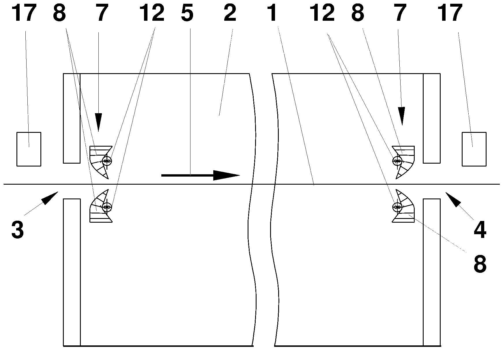
Die Erfindung betrifft eine Vorrichtung zum Behandeln einer Warenbahn (1), umfassend eine Behandlungskammer (2), Mittel zum Transportieren der Warenbahn (1) durch die Behandlungskammer (2), wobei die Behandlungskammer (2) einen Einlaufschlitz (3) und einen Auslaufschlitz (4) für die Warenbahn (1) aufweist, und Mittel (7) zum weitgehenden Abdichten des Einlaufschlitzes (3) und/oder des Auslaufschlitzes (4). Die Vorrichtung soll während des Betriebs im Bereich des Einlaufschlitzes (3) und/oder des Auslaufschlitzes (4) unabhängig von einer Form der Warenbahn (1) weitgehend abgedichtet werden können. Dies wird dadurch erreicht, dass die Mittel (7) zum Abdichten eine Vielzahl von Segmenten (8) umfassen, deren freie Enden (8.3) jeweils unterschiedlich in der Höhe einstellbar sind.

Figure DE102019100756A1_0000
The invention relates to a device for treating a material web (1), comprising a treatment chamber (2), means for transporting the material web (1) through the treatment chamber (2), the treatment chamber (2) having an inlet slot (3) and an outlet slot ( 4) for the web (1), and means (7) for largely sealing the inlet slot (3) and / or the outlet slot (4). The device should be able to be largely sealed during operation in the area of the inlet slot (3) and / or the outlet slot (4), regardless of the shape of the web (1). This is achieved in that the means (7) for sealing comprise a plurality of segments (8), the free ends (8.3) of which can each be adjusted in height differently.
Figure DE102019100756A1_0000

Description

Die Erfindung betrifft eine Vorrichtung zum Behandeln einer Warenbahn, umfassend eine Behandlungskammer, Mittel zum Transportieren der Warenbahn durch das Gehäuse, wobei die Behandlungskammer einen Einlaufschlitz und einen Auslaufschlitz für die Warenbahn aufweist, und Mittel zum weitgehenden Abdichten des Einlaufschlitzes und/oder des Auslaufschlitzes.The invention relates to a device for treating a web, comprising a treatment chamber, means for transporting the web through the housing, the treatment chamber having an inlet slot and an outlet slot for the web, and means for largely sealing the inlet slot and / or the outlet slot.

Solche Vorrichtungen sind an sich bekannt und z.B. in der DE 103 33 483 A1 beschrieben. Sie werden z.B. eingesetzt, um eine Warenbahn einer Wärmebehandlung zu unterziehen. Die Warenbahn ist z.B. aus Textil oder aus Papier und kann vor Einlauf in die Vorrichtung veredelt und/oder beschichtet worden sein. Die Vorrichtungen weisen einen Einlauf- und einen Auslaufschlitz auf, die oftmals mit Mitteln zum Abdichten versehen sind, um ein Eintreten von Falschluft (Gefahr von Kondensation) und/oder ein Austreten von Trocknungsluft (Energieverluste und gegebenenfalls Austreten von Schadstoffen) zu vermindern. Die Mittel zum Abdichten umfassen z.B. Düsen, die im Betrieb einen Luftvorhang bilden (beschrieben in DE 100 07 004 A1 ), oder elastische Dichtlippen (beschrieben in DE 1785 636 A ).
Die Mittel zum Abdichten dürfen in vielen Fällen nicht so ausgebildet sein, dass sie die Warenbahn berühren oder auf andere Weise die Oberfläche(n) und/oder Beschichtung(en) beeinflussen.
Such devices are known per se and for example in the DE 103 33 483 A1 described. They are used, for example, to heat-treat a web. The web of material is, for example, made of textile or paper and may have been finished and / or coated before it enters the device. The devices have an inlet and an outlet slot, which are often provided with means for sealing in order to reduce the occurrence of false air (risk of condensation) and / or the escape of drying air (energy losses and possibly leakage of pollutants). The sealing means comprise, for example, nozzles which form an air curtain during operation (described in DE 100 07 004 A1 ), or elastic sealing lips (described in DE 1785 636 A ).
In many cases, the sealing means must not be designed in such a way that they touch the web or influence the surface (s) and / or coating (s) in any other way.

In vielen Vorrichtungen zum Behandeln einer Warenbahn ist diese nicht in einer Ebene glatt gespannt, sondern bildet eine konkave oder konvexe Wölbung. Diese Wölbung ist abhängig von der Qualität - insbesondere einem Gewicht - der Warenbahn und einer auf diese einwirkende Querspannung. Hierbei können die bekannten Mittel zum Abdichten nicht ausreichend an die jeweilige Form der Warenbahn angepasst werden, so dass ein offen bleibender Querschnitt des Schlitzes relativ groß und die Dichtwirkung entsprechend unbefriedigend ist.In many devices for treating a material web, it is not tensioned smoothly in one plane, but forms a concave or convex curvature. This curvature depends on the quality - in particular a weight - of the material web and a transverse tension acting on it. In this case, the known means for sealing cannot be adequately adapted to the respective shape of the web, so that an open cross section of the slot is relatively large and the sealing effect is accordingly unsatisfactory.

Es ist daher die Aufgabe der Erfindung, eine Vorrichtung zum Behandeln einer Warenbahn zu schaffen, die während des Betriebs im Bereich eines Einlaufschlitzes und/oder eines Auslaufschlitzes unabhängig von einer Form der Warenbahn weitgehend abgedichtet werden kann, ohne dass ein negativer Einfluss auf eine oder beide Oberflächen der Warenbahn erfolgt.It is therefore the object of the invention to provide a device for treating a web that can be largely sealed during operation in the area of an inlet slot and / or an outlet slot, regardless of the shape of the web, without having a negative influence on one or both Surface of the web is done.

Die Aufgabe ist durch die Merkmale des Anspruchs 1 gelöst. Die Mittel zum Abdichten umfassen eine Vielzahl von Segmenten, deren freie Enden jeweils unterschiedlich in der Höhe, das heißt senkrecht zu den idealisiert ebenen Hauptflächen der Warenbahn, einstellbar sind. Hierdurch kann eine Form eines offenen Teils - eines Spalts - des Einlaufschlitzes weitgehend an eine Wölbung der Warenbahn angepasst werden, so dass der Spalt insgesamt sehr schmal sein kann. Je größer die Anzahl der Segmente je Längeneinheit, desto genauer ist die Anpassung an die Form der Warenbahn. Insgesamt wird unter der Berücksichtigung, dass die Oberflächen der Warenbahn nicht von den Mitteln zum Abdichten berührt werden, die Vorrichtung bestmöglich abgedichtet, und es können nur geringe Mengen an Falschluft eintreten bzw. an Behandlungsluft austreten. Die Behandlung der Warenbahn und der Energiehaushalt der Vorrichtung werden insgesamt verbessert.The object is solved by the features of claim 1. The means for sealing comprise a multiplicity of segments, the free ends of which can each be set differently in height, that is to say perpendicularly to the idealized flat main surfaces of the material web. As a result, a shape of an open part - a gap - of the inlet slot can largely be adapted to a curvature of the material web, so that the gap as a whole can be very narrow. The greater the number of segments per unit length, the more precise the adaptation to the shape of the web. Overall, taking into account that the surfaces of the material web are not touched by the sealing means, the device is sealed as best as possible, and only small amounts of incorrect air can enter or treatment air can escape. The treatment of the web and the energy balance of the device are improved overall.

Die Unteransprüche betreffen die vorteilhafte Ausgestaltung der Erfindung.The subclaims relate to the advantageous embodiment of the invention.

In einer Ausgestaltung erfolgt das Verstellen der freien Enden mittels einer inhärenten Bewegungsautomatik. Eine solche ist z.B. als Fin Ray bekannt. Die Bewegungsautomatik wird durch eine Vielzahl von in sich steifen Stegen bewirkt, die gelenkartig innen an Wandungen des Segments befestigt sind. Hierdurch ist eine relativ gute und einfache Anpassung an die Form der Warenbahn gegeben.In one embodiment, the free ends are adjusted by means of an inherent automatic movement. Such is e.g. known as Fin Ray. The automatic movement is brought about by a large number of rigid webs which are fastened to the inside of the segment in the manner of joints. This results in a relatively good and simple adaptation to the shape of the web.

In einer weiteren Ausgestaltung ist zum Verstellen der Segmente ein Rundstab angeordnet. Dieser ist entsprechend der Wölbung der Warenbahn elastisch biegbar. Der runde Querschnitt gewährleistet eine definierte Berührungsfläche des Stabes an die Segmente und damit eine hohe Präzision der Verstellung.In a further embodiment, a round bar is arranged to adjust the segments. This is elastically bendable according to the curvature of the web. The round cross-section ensures a defined contact area of the rod with the segments and thus a high precision of the adjustment.

In einer weiteren Ausgestaltung ist zum Verstellen ein Truss-Rod angeordnet (Zug-/Druckstab; bekannt z.B. als Halsspannstab für Saiteninstrumente, besonders für Gitarren). Der Truss-Rod besteht aus zwei Stäben, deren Enden aneinander befestigt sind. Hierbei ist z.B. an zugeordneten ersten der Enden eine feste Verbindung und an zugeordneten zweiten der Enden eine einstellbar verschiebbare Verbindung angeordnet, z.B. mittels Gewinden, die ein Spannelement bilden. Je nach einer eingestellten Spannung ist der Rundstab gerade oder in eine von zwei entgegengesetzten Richtungen gebogen. Hierdurch ist das Verstellen einfach durch Änderung einer Spannung eines Spannelementes durchführbar.In a further embodiment, a truss rod is arranged for adjustment (tension / compression rod; known, for example, as a neck tension rod for string instruments, especially for guitars). The truss rod consists of two rods, the ends of which are attached to each other. Here, e.g. a fixed connection is arranged at assigned first of the ends and an adjustable, displaceable connection is arranged at assigned second of the ends, e.g. by means of threads that form a clamping element. Depending on a set tension, the round bar is straight or bent in one of two opposite directions. As a result, the adjustment can be carried out simply by changing a tension of a tensioning element.

In einer weiteren Ausgestaltung sind die Mittel zum Verstellen zum automatischen Anpassen an eine Lage der Warenbahn ausgerüstet. Hierdurch weist der Spalt immer eine optimale Weite auf.In a further embodiment, the means for adjusting are equipped for automatic adjustment to a position of the web. As a result, the gap always has an optimal width.

In einer weiteren Ausgestaltung ist mindestens ein Näherungssensor zum Bestimmen der Lage der Warenbahn angeordnet. Dies erleichtert entsprechende Kontrollen, so dass eine Gefahr reduziert wird, dass die Warenbahn obere und/oder untere Begrenzungen des Spaltes berührt. Anderseits kann mit dem Näherungssensor ein sicheres Signal erzeugt werden, das als Leitgröße für eine automatische Regelung der Weite des Spalts genutzt werden kann.In a further embodiment, at least one proximity sensor is arranged to determine the position of the web. This facilitates appropriate controls, so that a risk is reduced that the web touches the upper and / or lower boundaries of the gap. On the other hand, a safe signal can be generated with the proximity sensor that can be used as a guide for automatic control of the width of the gap.

In einer weiteren Ausgestaltung sind Mittel zum Anpassen der Mittel zum Abdichten an eine Breite der Warenbahn angeordnet. Hierdurch kann die Breite des Spalts auf einen optimalen Wert minimiert werden.In a further embodiment, means for adapting the means for sealing to a width of the web are arranged. In this way, the width of the gap can be minimized to an optimal value.

In einer weiteren Ausgestaltung ist eine Wandung des Segments aus einem elastisch verformbaren Material gefertigt. Dies erleichtert die Einstellung der Mittel zum Abdichten, weil eine Rückstellung eines ausgelenkten Segments bei einer Entlastung selbsttätig erfolgt. Im Zusammenspiel mit den Stegen weist das Segment trotz der verformbaren Außenhaut eine gute Gesamtstabilität auf.In a further embodiment, a wall of the segment is made from an elastically deformable material. This makes it easier to set the sealing means because a deflected segment is automatically reset when the load is released. In combination with the webs, the segment has good overall stability despite the deformable outer skin.

In einer weiteren Ausgestaltung weist das Segment eine hohe Quersteifigkeit auf. Dies verhindert eine gegenseitige Störung bei der Verstellung der einzelnen Segmente.In a further embodiment, the segment has high transverse rigidity. This prevents mutual interference when adjusting the individual segments.

In einer weiteren Ausgestaltung sind die Mittel zum Abdichten höhenverstellbar gelagert. Dies bietet eine von mehreren Möglichkeiten zum Anpassen an eine durchhängende oder an eine aufwölbende Warenbahn.In a further embodiment, the means for sealing are height-adjustable. This offers one of several options for adapting to a sagging or an arching web.

Alternativ oder zusätzlich zur Höhenverstellbarkeit sind zum selben Zweck die Mittel zum Abdichten im Bereich der freien Enden überlappend angeordnet.As an alternative or in addition to the height adjustability, the means for sealing are arranged to overlap in the region of the free ends for the same purpose.

Die Erfindung wird anhand der beigefügten schematischen Zeichnung weiter erläutert. Dabei zeigen

  • 1 einen Querschnitt einer Vorrichtung zum Behandeln einer Warenbahn,
  • 2 eine Ansicht auf einen Einlaufschlitz der Vorrichtung mit Spannketten,
  • 3 eine perspektivische Ansicht eines Segments,
  • 4 einen Längsschnitt sowie eine perspektivische Ansicht (4a) eines Verstellstabs,
  • 5 einen Querschnitt durch den Verstellstab der 4 und
  • 6 einen Querschnitt durch den Einlaufschlitz der 2 in a) passivem und b) aktiviertem Zustand.
The invention is further explained with the aid of the attached schematic drawing. Show
  • 1 3 shows a cross section of a device for treating a material web,
  • 2nd 2 shows a view of an inlet slot of the device with tension chains,
  • 3rd a perspective view of a segment,
  • 4th a longitudinal section and a perspective view ( 4a) an adjustment rod,
  • 5 a cross section through the adjusting rod 4th and
  • 6 a cross section through the inlet slot of the 2nd in a) passive and b) activated state.

Wie aus der 1 ersichtlich umfasst eine Vorrichtung zum Behandeln einer Warenbahn 1 eine im Wesentlichen geschlossene Behandlungskammer 2, die einen Einlaufschlitz 3 und einen Auslaufschlitz 4 als Durchlässe für die Warenbahn 1 aufweist. Die Warenbahn 1 wird längs in Richtung des Pfeils 5, hier in einer horizontalen Ebene, durch die Behandlungskammer 2 transportiert, die mindestens eine Zone aufweist. Hierbei ist die Warenbahn 1 an ihren Längskanten mittels in der 2 dargestellten Haltern 6 - z.B. Nadeln oder Kluppen, die an in Schienen 6.1 verfahrbar gelagerten Ketten befestigt sind - mit vorbestimmter Querspannung gehalten. Die Schienen 6.1, die Ketten und die Nadeln oder Kluppen sind Teile der Mittel zum Transportieren der Warenbahn 1. Der Einlaufschlitz 3 und der Auslaufschlitz 4 sind durch Mittel 7 zum Abdichten so weit wie möglich verschlossen, ohne dass eine Gefahr besteht, dass die Mittel 7 zum Abdichten die Warenbahn 1 berühren.As from the 1 evidently includes a device for treating a web 1 an essentially closed treatment chamber 2nd that have an inlet slot 3rd and an outlet slot 4th as passages for the web 1 having. The web 1 will be along in the direction of the arrow 5 , here in a horizontal plane, through the treatment chamber 2nd transported that has at least one zone. Here is the web 1 on its longitudinal edges by means of 2nd illustrated holders 6 - Eg needles or clips that are attached to rails 6.1 movably mounted chains are attached - held with a predetermined transverse tension. The rails 6.1 , the chains and the needles or clips are part of the means for transporting the web 1 . The inlet slot 3rd and the outlet slot 4th are by means 7 sealed for sealing as much as possible without any risk of the agent 7 to seal the web 1 touch.

Wie aus den 2 bis 4 ersichtlich ist, umfassen die Mittel 7 zum Abdichten eine Vielzahl von Segmenten 8, die in zwei lückenlosen Reihen über mindestens die gesamte Breite des Schlitzes 3, 4 überlappend oder oberhalb und unterhalb der Warenbahn 1 angeordnet sind und in passivem Zustand den Einlaufschlitz 3 bzw. den Auslaufschlitz 4 zumindest weitgehend verschließen. Idealerweise bleibt in aktivem Zustand lediglich ein schmaler Spalt mit einem vorbestimmten Spiel zu der Warenbahn 1 geöffnet.Like from the 2nd to 4th can be seen include the funds 7 to seal a variety of segments 8th that are in two gapless rows across at least the entire width of the slot 3rd , 4th overlapping or above and below the web 1 are arranged and in the passive state the inlet slot 3rd or the outlet slot 4th at least largely close it. Ideally, only a narrow gap with a predetermined play to the web remains in the active state 1 open.

Jedes der Segmente 8 ist derart ausgestaltet, dass eine Krafteinwirkung an einer Stelle des Segments 8 eine inhärente Verformung an einer anderen Stelle des Segments 8 bewirkt. Solche inhärente Verformungen sind z.B. in der DE 199 16 411 A1 , der EP 0 860 355 A1 und der EP 0 045 713 A1 beschrieben.Each of the segments 8th is designed such that a force is applied at one point in the segment 8th an inherent deformation elsewhere in the segment 8th causes. Such inherent deformations are eg in the DE 199 16 411 A1 , of the EP 0 860 355 A1 and the EP 0 045 713 A1 described.

Das Segment 8 hat eine Breite von 2 cm bis 10 cm, vorzugsweise von 3 cm bis 5 cm.The segment 8th has a width of 2 cm to 10 cm, preferably 3 cm to 5 cm.

Jedes der Segmente 8, das in der 3 deutlicher dargestellt ist, weist ohne Wirkung einer Punkt- oder Linienlast im Wesentlichen einen Querschnitt in Form eines gleichschenkligen spitzen Dreiecks auf; das bedeutet, Wandungen 8.1, 8.2 des Segments 8 bilden die Schenkel und eine Hypotenuse des Dreiecks. Dreieckförmige Hauptflächen des Segments 8, die rechtwinklig zu den Wandungen 8.1, 8.2 sind, sind im Wesentlichen - mit Ausnahme von Stegen 9 - offen. Ein zwischen den Schenkeln des Dreiecks gebildeter Winkel beträgt ca. 30°, und eine Höhe des Dreiecks beträgt ca. 20 cm. Eine Stärke der Wandungen 8.1, die die Schenkel bilden, nimmt von der Hypotenuse 8.2 zu einer Spitze 8.3 des Dreiecks ab. Alle Wandungen 8.1, 8.2 des Segments 8 sind aus einem elastischen Material gefertigt, das in einem weiten Bereich von 0°C bis 250°C temperaturstabil ist. Ein geeignetes Material ist z.B. Silikon, das gleichzeitig den Vorteil hat, schwer entflammbar und leicht zu reinigen zu sein.Each of the segments 8th that in the 3rd is more clearly shown, has essentially a cross section in the form of an isosceles triangle without effect of a point or line load; that means walls 8.1 , 8.2 of the segment 8th form the legs and a hypotenuse of the triangle. Triangular main faces of the segment 8th that are perpendicular to the walls 8.1 , 8.2 are, are essentially - with the exception of webs 9 - open. An angle formed between the legs of the triangle is approximately 30 ° and the height of the triangle is approximately 20 cm. A strength of the walls 8.1 that form the thighs takes off from the hypotenuse 8.2 to a top 8.3 of the triangle. All walls 8.1 , 8.2 of the segment 8th are made of an elastic material that is temperature stable in a wide range from 0 ° C to 250 ° C. A suitable material is, for example, silicone, which also has the advantage of being flame-retardant and easy to clean.

Die Konstruktion des Segments 8 als Hohlkörper gewährleistet eine gute Wärmeisolation.The construction of the segment 8th as a hollow body ensures good thermal insulation.

Vorzugsweise ist das Segment 8 in seiner Breite zu der Spitze 8.3 des Dreiecks, die ein freies Ende 8.3 des Segments 8 bildet, hin leicht verjüngt; die Breite jeder der Wandungen 8.1, die einen der Schenkel bildet, nimmt hier stetig und symmetrisch von, nach der 3, oben nach unten um ca. ½ mm ab; diese Abnahme kann auch sprunghaft in einer Stufe ausgebildet sein. Hierdurch wird ein gegenseitiges Verklemmen benachbarter Segmente 8 verhindert und die selbsttätige Rückverformung nach einer Auslenkung der Spitze 8.3, also des freien Endes 8.3, erleichtert. Preferably the segment 8th in width to the top 8.3 of the triangle that has a free end 8.3 of the segment 8th forms, slightly tapered; the width of each of the walls 8.1 , which forms one of the legs, decreases steadily and symmetrically from here to the 3rd , from top to bottom by approx. ½ mm; this decrease can also be erratic in one step. This will cause jamming of adjacent segments 8th prevents and automatic recovery after a deflection of the tip 8.3 , so the free end 8.3 , facilitated.

Zwischen den Schenkeln ist eine Vielzahl von hier fünf Stegen 9 angeordnet, die gleichmäßig beabstandet parallel zu der Hypotenuse verlaufen und an den Schenkeln gelenkartig befestigt sind. Jeder der Stege 9 ist aus einem steifen Material oder vorzugsweise durch entsprechend dickere Materialstärke bei Verwendung des Materials der Wandungen 8.1, 8.2 steifer gefertigt. Für die gelenkartige Befestigung ist ein Übergang zwischen der zugeordneten Wandung und dem Steg 9 aus dünnem elastischem Material gebildet, vorzugsweise aus demselben Material wie die Wandungen 8.1, 8.2.There is a large number of five webs between the legs 9 arranged, which are evenly spaced parallel to the hypotenuse and are attached to the legs like a joint. Each of the piers 9 is made of a rigid material or preferably by a correspondingly thicker material thickness when using the material of the walls 8.1 , 8.2 made stiffer. For the articulated fastening there is a transition between the assigned wall and the web 9 formed from thin elastic material, preferably from the same material as the walls 8.1 , 8.2 .

An der die Hypotenuse bildenden Wandung 8.2 des Segments 8 sind nach außen weisend zwei Füße 10 mit gegenseitigem Abstand in Längsrichtung der Hypotenuse zur Befestigung des Segments 8 an einer Trägerschiene angeordnet.On the wall forming the hypotenuse 8.2 of the segment 8th are two feet pointing outwards 10th with mutual spacing in the longitudinal direction of the hypotenuse for fastening the segment 8th arranged on a support rail.

In einer der die Schenkel bildenden Wandungen 8.1 sind an der Außenseite zwei Hinterschneidungen 11 angeordnet. Diese sind in einem Bereich dieser Wandung 8.1 angebracht, die für einen Angriff eines Verstellstabes 12 vorgesehen ist. Hierdurch ist ein Angriffspunkt des Verstellstabes 12 genauer definiert und somit eine Höhe des freien Endes 8.3 exakter und gleichmäßiger einstellbar.In one of the walls forming the legs 8.1 there are two undercuts on the outside 11 arranged. These are in an area of this wall 8.1 attached, for an attack of an adjusting rod 12th is provided. This is a point of attack for the adjusting rod 12th more precisely defined and thus a height of the free end 8.3 more precise and evenly adjustable.

Der Verstellstab 12, der in den 4 und 5 dargestellt ist, umfasst eine rohrartige Hülle 13, in der zwei längliche Stäbe 14, 15 gelagert sind. In der Hülle 13 ist im Bereich jedes ihrer Enden ein Lagerbock 16 unverrückbar zu der Hülle 13 befestigt. Ein erster der Stäbe 14 ist an jedem seiner beiden Enden unverrückbar in einem zugehörigen der Lagerböcke 16 befestigt, während ein zweiter der Stäbe 15 in Gewindebohrungen der Lagerböcke 16 drehbar gelagert ist. Hierfür weist der zweite Stab 15 in seinen Endbereichen jeweils ein Außengewinde auf. Die Gewindebohrungen und die Außengewinde sind an einem Ende der Hülle 13 als Linksgewinde und an dem entgegengesetzten Ende als Rechtsgewinde ausgebildet, so dass eine Drehung des zweiten Stabes 15 um seine Längsachse seine Längenänderung zwischen den Lagerböcken 16 bewirkt. Der zweite Stab 15 ist von Hand oder motorisch antreibbar.The adjustment rod 12th who in the 4th and 5 is shown comprises a tubular casing 13 , in which two elongated rods 14 , 15 are stored. In the shell 13 is a bearing block in the area of each of its ends 16 immovable to the shell 13 attached. A first of the bars 14 is immovable at each of its two ends in an associated one of the pedestals 16 attached while a second of the bars 15 in threaded holes in the pedestals 16 is rotatably mounted. The second staff points to this 15 an external thread in each of its end areas. The threaded bores and the external threads are at one end of the sleeve 13 formed as a left-hand thread and at the opposite end as a right-hand thread, so that rotation of the second rod 15 around its longitudinal axis its change in length between the bearing blocks 16 causes. The second staff 15 can be driven by hand or by motor.

Bei einem neutralen geradlinigen Verlauf des Verstellstabes 12 sind die Längen der Stäbe 14, 15 zwischen den Lagerböcken 16 gleich.With a neutral straight line of the adjustment rod 12th are the lengths of the bars 14 , 15 between the pedestals 16 equal.

Einer der Lagerböcke 16 ist fest und der andere axial (bezogen auf den Verstellstab 12) verschiebbar gelagert.One of the pillow blocks 16 is fixed and the other is axial (based on the adjustment rod 12th ) slidably mounted.

In der 4b ist weiterhin ein Beispiel eines durch Drehung des zweiten Stabes 15 bogenförmig gekrümmten Verstellstabes 12 unmaßstäblich verkleinert und perspektivisch ohne weitere Details gezeigt.In the 4b is further an example of one by rotating the second rod 15 curved curved adjustment rod 12th scaled down to scale and shown in perspective without further details.

Jeder Reihe von Segmenten 8 ist einer der Verstellstäbe 12 zugeordnet; also sind z.B. dem Einlaufschlitz 3 zwei Verstellstäbe 12 zugeordnet. Diese sind beabstandet übereinander dicht oder berührend an den zugeordneten Segmenten 8 und horizontal in Längsrichtung der Warenbahn 1 hin und her verschiebbar in der Behandlungskammer 2 befestigt. Hierbei befinden sich Längsachsen beider Stäbe 14, 15 in einer horizontalen Ebene, und die Berührung ist in einem vorbestimmten Bereich der den Schenkel bildenden Wandung 8.1. Die Verschiebung erfolgt von Hand oder motorisch.Any number of segments 8th is one of the adjustment rods 12th assigned; So, for example, are the inlet slot 3rd two adjustment rods 12th assigned. These are spaced one above the other close or touching the assigned segments 8th and horizontally in the longitudinal direction of the web 1 can be moved back and forth in the treatment chamber 2nd attached. Here are the longitudinal axes of both bars 14 , 15 in a horizontal plane, and the contact is in a predetermined area of the wall forming the leg 8.1 . The shift is done by hand or by motor.

Die Wirkung der Krafteinwirkung durch den Verstellstab 12 auf die Segmente 8 ist in der 6 beispielhaft veranschaulicht, wobei hier die Segmente 8 sich bei dem passiven, also unverformten Zustand in der Höhe überlappen (aus der Zeichnung nur indirekt ersichtlich). Die 6a zeigt den Einlaufschlitz 3 bei einer (idealisiert) ebenen Form oder in einem Randbereich der Warenbahn 1. Hierbei liegt der Verstellstab 12 mit Krafteinwirkung an den Segmenten 8 so an, dass der Einlaufschlitz 3 als schmaler Spalt zwischen den gekrümmten Segmenten 8 gebildet ist. Die Segmente 8 weisen hier die aktive, also gekrümmte Form auf. Ein Abstand der Segmente 8 zu der Warenbahn 1 ist sehr gering.The effect of the force applied by the adjustment rod 12th on the segments 8th is in the 6 exemplified, with here the segments 8th in the passive, i.e. undeformed state, they overlap in height (can only be seen indirectly from the drawing). The 6a shows the inlet slot 3rd with an (idealized) flat shape or in an edge area of the web 1 . Here is the adjustment rod 12th with force on the segments 8th so that the inlet slot 3rd as a narrow gap between the curved segments 8th is formed. The segments 8th have the active, i.e. curved shape. A spacing of the segments 8th to the web 1 is very low.

Nach der 6b ist die Warenbahn 1 senkrecht zur Zeichnungsebene nach unten gewölbt. Auf das nach der 6b untere, beispielhaft mittlere Segment 8 wird durch den Verstellstab 12 infolge dessen Verschiebung zu dem Segment 8 hin (durch Drehung des zweiten Stabes 15 oder durch horizontale Verschiebung) eine Kraft auf dieses ausgeübt. Das Segment 8 verformt sich derart, dass das freie Ende 8.3 nach unten gebogen ist und so der Auslenkung der Warenbahn 1 aus einer horizontalen Spannebene folgt. Das obere hier ebenfalls mittlere Segment 8 ist ohne Krafteinwirkung und daher unverformt, also in einer Zeichnungsebene, dreieckförmig. Zu den Rändern der Warenbahn 1 hin nimmt die Verformung der einzelnen oberen Segmente 8 infolge geringerer Krafteinwirkung quasikontinuierlich zu, während die der einzelnen unteren Segmente 8 entsprechend abnimmt. Hierdurch ist die freie Fläche des Spalts optimal minimiert und an die Form der Warenbahn 1 angepasst.After 6b is the web 1 arched downwards perpendicular to the plane of the drawing. After that 6b lower, exemplary middle segment 8th is through the adjustment rod 12th as a result of which shift to the segment 8th towards (by turning the second stick 15 or by horizontal displacement) exerted a force on it. The segment 8th deforms such that the free end 8.3 is bent down and so the deflection of the web 1 follows from a horizontal clamping plane. The upper segment, also middle here 8th is without force and therefore undeformed, i.e. in a drawing plane, triangular. To the edges of the web 1 the deformation of the individual upper segments decreases 8th due to the lower application of force quasi-continuously, while that of the individual lower segments 8th decreases accordingly. This is the free area of the gap optimally minimized and to the shape of the web 1 customized.

Für den Einlaufschlitz 3 und für den Auslaufschlitz 4 ist jeweils ein Gestell vorgesehen, in dem der Verstellstab 12 und die Trägerschiene mit den daran in Reihen befestigten Segmenten 8 jeweils oberhalb und unterhalb der Ebene der Warenbahn 1 gelagert sind. Das Gestell kann in der Behandlungskammer 2 höhenverstellbar befestigt sein.For the inlet slot 3rd and for the outlet slot 4th a frame is provided, in which the adjusting rod 12th and the support rail with the segments attached to it in rows 8th each above and below the level of the web 1 are stored. The rack can be in the treatment chamber 2nd be attached height adjustable.

Der Vorrichtung ist mindestens ein Näherungssensor 17 zum Bestimmen der Lage der Warenbahn 1 zugeordnet, der vorzugsweise vor der Behandlungskammer 2 befestigt ist. Nach dem Ausführungsbeispiel sind zwei Näherungssensoren 17 angeordnet, einer vor und einer hinter der Behandlungskammer 2.The device is at least one proximity sensor 17th to determine the position of the web 1 assigned, preferably in front of the treatment chamber 2nd is attached. According to the exemplary embodiment, there are two proximity sensors 17th arranged, one in front and one behind the treatment chamber 2nd .

Im Betrieb wird die Behandlungskammer 2 auf eine vorbestimmte Temperatur beheizt, z.B. mittels erwärmter Umluft. Die Warenbahn 1 wird in Bereichen ihre Längskanten vor der Behandlungskammer 2 z.B. durch Aufnadeln an den Mitteln zum Transportieren befestigt, quer zu der Transportrichtung 5 gespannt und durch den Einlaufschlitz 3 in die Behandlungskammer 2 gefördert. Hier wird die Warenbahn 1 entsprechend den Anforderungen behandelt. Nach der Behandlung wird die Warenbahn 1 durch den Auslaufschlitz 4 aus der Behandlungskammer 2 geführt und einer weiteren Verarbeitung zugeführt, z.B. einer Inspektion und einer Wickelvorrichtung.The treatment chamber is in operation 2nd heated to a predetermined temperature, for example by means of heated circulating air. The web 1 is in areas of their longitudinal edges in front of the treatment chamber 2nd eg attached to the means for transport by needling, transversely to the direction of transport 5 cocked and through the inlet slot 3rd into the treatment chamber 2nd promoted. Here is the web 1 treated according to the requirements. After the treatment, the material web 1 through the outlet slot 4th from the treatment chamber 2nd guided and fed to further processing, for example an inspection and a winding device.

Die Spalte der Schlitze 3, 4 sind zunächst entsprechend einer erwarteten Lage und Form der Warenbahn 1, insbesondere deren Breite und Wölbung, voreingestellt. Hierfür sind die Verstellstäbe 12 bei geradlinigem Verlauf so an alle Segmente 8 gedrückt, dass deren freie Enden 8.3 einen Teil des Schlitzes 3, 4 zwischen den Reihen der Segmente 8 als den Spalt freigeben. Weiterhin werden die zweiten Stäbe 15 derart gedreht, dass eine Wölbung des freigegebenen Teils des Schlitzes 3, 4 der erwarteten Wölbung der Warenbahn 1 entspricht. Eine Fein- und Nacheinstellung des freien Teils des Schlitzes 3, 4 erfolgt während des Einfahrens und des Betriebs der Vorrichtung durch entsprechendes horizontales Verschieben des Verstellstabes 12 insgesamt und/oder Drehen des zweiten Stabes 15.The column of the slots 3rd , 4th are initially in accordance with an expected location and shape of the material web 1 , especially their width and curvature. The adjustment rods are for this 12th with a straight line to all segments 8th pressed that their free ends 8.3 part of the slot 3rd , 4th between the rows of segments 8th than release the gap. Furthermore, the second rods 15 rotated such that a curvature of the released part of the slot 3rd , 4th the expected curvature of the web 1 corresponds. A fine and readjustment of the free part of the slot 3rd , 4th takes place during the retraction and operation of the device by corresponding horizontal displacement of the adjusting rod 12th total and / or rotating the second rod 15 .

Das Verschieben und Verdrehen erfolgt z.B. mittels der Motore, die vorzugsweise mittels einer Steuer- und Regeleinrichtung anhand von Signalen des Näherungssensors 17 angesteuert werden.The displacement and rotation takes place, for example, by means of the motors, which are preferably by means of a control and regulating device based on signals from the proximity sensor 17th can be controlled.

Es ist alternativ möglich, die Segmente 8 ohne die Überlappung anzuordnen. Das Gestell, in dem die Verstellstäbe 12 und die Trägerschiene gelagert sind, ist in diesem Fall höhenverstellbar.It is alternatively possible to use the segments 8th without arranging the overlap. The frame in which the adjustment rods 12th and the support rail is mounted, is height adjustable in this case.

BezugszeichenlisteReference list

11
WarenbahnGoods web
22nd
BehandlungskammerTreatment chamber
33rd
EinlaufschlitzInlet slot
44th
AuslaufschlitzOutlet slot
55
Pfeil (Transportrichtung)Arrow (transport direction)
66
Halterholder
6.16.1
Schienerail
77
Mittel zum AbdichtenSealing means
88th
Segmentsegment
8.18.1
WandungWall
8.28.2
WandungWall
8.38.3
EndeThe End
99
Stegweb
1010th
Fußfoot
1111
HinterschneidungUndercut
1212th
VerstellstabAdjustment rod
1313
HülleCover
1414
erster Stabfirst staff
1515
zweiter Stabsecond staff
1616
LagerbockBearing block
1717th
NäherungssensorProximity sensor

ZITATE ENTHALTEN IN DER BESCHREIBUNG QUOTES INCLUDE IN THE DESCRIPTION

Diese Liste der vom Anmelder aufgeführten Dokumente wurde automatisiert erzeugt und ist ausschließlich zur besseren Information des Lesers aufgenommen. Die Liste ist nicht Bestandteil der deutschen Patent- bzw. Gebrauchsmusteranmeldung. Das DPMA übernimmt keinerlei Haftung für etwaige Fehler oder Auslassungen.This list of documents listed by the applicant has been generated automatically and is only included for the better information of the reader. The list is not part of the German patent or utility model application. The DPMA assumes no liability for any errors or omissions.

Zitierte PatentliteraturPatent literature cited

  • DE 10333483 A1 [0002]DE 10333483 A1 [0002]
  • DE 10007004 A1 [0002]DE 10007004 A1 [0002]
  • DE 1785636 A [0002]DE 1785636 A [0002]
  • DE 19916411 A1 [0020]DE 19916411 A1 [0020]
  • EP 0860355 A1 [0020]EP 0860355 A1 [0020]
  • EP 0045713 A1 [0020]EP 0045713 A1 [0020]

Claims (11)

Vorrichtung zum Behandeln einer Warenbahn (1), umfassend eine Behandlungskammer (2), Mittel zum Transportieren der Warenbahn (1) durch die Behandlungskammer (2), wobei die Behandlungskammer (2) einen Einlaufschlitz (3) und einen Auslaufschlitz (4) für die Warenbahn (1) aufweist, und Mittel (7) zum weitgehenden Abdichten des Einlaufschlitzes (3) und/oder des Auslaufschlitzes (4), dadurch gekennzeichnet, dass die Mittel (7) zum Abdichten eine Vielzahl von Segmenten (8) umfassen, deren freie Enden (8.3) jeweils unterschiedlich in der Höhe einstellbar sind.Device for treating a web (1), comprising a treatment chamber (2), means for transporting the web (1) through the treatment chamber (2), the treatment chamber (2) having an inlet slot (3) and an outlet slot (4) for the Material web (1), and means (7) for largely sealing the inlet slot (3) and / or the outlet slot (4), characterized in that the means (7) for sealing comprise a plurality of segments (8), the free The ends (8.3) are each adjustable in height. Vorrichtung nach Anspruch 1, dadurch gekennzeichnet, dass das Verstellen der freien Enden nach Art eines Fin Ray erfolgt.Device after Claim 1 , characterized in that the adjustment of the free ends is done in the manner of a fin ray. Vorrichtung nach Anspruch 2, dadurch gekennzeichnet, dass zum Verstellen ein Verstellstab (12) mit rundem Querschnitt angeordnet ist.Device after Claim 2 , characterized in that an adjusting rod (12) with a round cross section is arranged for adjustment. Vorrichtung nach einem der Ansprüche 1 bis 3, dadurch gekennzeichnet, dass zum Verstellen ein Truss-Rod angeordnet ist.Device according to one of the Claims 1 to 3rd , characterized in that a truss rod is arranged for adjustment. Vorrichtung nach einem der Ansprüche 1 bis 4, dadurch gekennzeichnet, dass die Mittel zum Verstellen zum automatischen Anpassen an eine Lage der Warenbahn (1) ausgerüstet sind.Device according to one of the Claims 1 to 4th , characterized in that the means for adjusting for automatic adjustment to a position of the web (1) are equipped. Vorrichtung nach Anspruch 5, dadurch gekennzeichnet, dass mindestens ein Näherungssensor (17) zum Bestimmen der Lage der Warenbahn (1) angeordnet ist.Device after Claim 5 , characterized in that at least one proximity sensor (17) is arranged for determining the position of the material web (1). Vorrichtung nach einem der Ansprüche 1 bis 6, dadurch gekennzeichnet, dass Mittel zum Anpassen der Mittel zum Abdichten an eine Breite der Warenbahn (1) angeordnet sind.Device according to one of the Claims 1 to 6 , characterized in that means for adapting the means for sealing to a width of the web (1) are arranged. Vorrichtung nach einem der Ansprüche 1 bis 7, dadurch gekennzeichnet, dass eine Wandung (8.1, 8.2) des Segments (8) aus einem elastisch verformbaren Material gefertigt ist.Device according to one of the Claims 1 to 7 , characterized in that a wall (8.1, 8.2) of the segment (8) is made of an elastically deformable material. Vorrichtung nach einem der Ansprüche 1 bis 8, dadurch gekennzeichnet, dass das Segment (8) eine hohe Quersteifigkeit aufweist.Device according to one of the Claims 1 to 8th , characterized in that the segment (8) has a high transverse rigidity. Vorrichtung nach einem der Ansprüche 1 bis 9, dadurch gekennzeichnet, dass die Mittel (7) zum Abdichten in einem Gestell gelagert sind, das höhenverstellbar in der Behandlungskammer (2) befestigt ist.Device according to one of the Claims 1 to 9 , characterized in that the means (7) for sealing are mounted in a frame which is fixed in the treatment chamber (2) so as to be adjustable in height. Vorrichtung nach einem der Ansprüche 1 bis 10, dadurch gekennzeichnet, dass die Mittel (7) zum Abdichten überlappend angeordnet sind.Device according to one of the Claims 1 to 10th , characterized in that the means (7) for sealing are arranged to overlap.
DE102019100756.9A 2019-01-14 2019-01-14 Device for treating a web Pending DE102019100756A1 (en)

Priority Applications (4)

Application Number Priority Date Filing Date Title
DE102019100756.9A DE102019100756A1 (en) 2019-01-14 2019-01-14 Device for treating a web
EP19832299.2A EP3911904A1 (en) 2019-01-14 2019-12-12 Device for treating a material web
CN201980089046.6A CN113557402B (en) 2019-01-14 2019-12-12 Device for treating a material web
PCT/EP2019/084789 WO2020148033A1 (en) 2019-01-14 2019-12-12 Device for treating a material web

Applications Claiming Priority (1)

Application Number Priority Date Filing Date Title
DE102019100756.9A DE102019100756A1 (en) 2019-01-14 2019-01-14 Device for treating a web

Publications (1)

Publication Number Publication Date
DE102019100756A1 true DE102019100756A1 (en) 2020-07-16

Family

ID=69137838

Family Applications (1)

Application Number Title Priority Date Filing Date
DE102019100756.9A Pending DE102019100756A1 (en) 2019-01-14 2019-01-14 Device for treating a web

Country Status (4)

Country Link
EP (1) EP3911904A1 (en)
CN (1) CN113557402B (en)
DE (1) DE102019100756A1 (en)
WO (1) WO2020148033A1 (en)

Citations (11)

* Cited by examiner, † Cited by third party
Publication number Priority date Publication date Assignee Title
DE886588C (en) * 1950-02-20 1953-08-17 Willy Ing Weber Suction cup for suction machines for tissue
DE1785636A1 (en) 1964-04-16 1973-11-15 Famatex Gmbh Fabrik Fuer Texti DEVICE FOR FASTENING FABRICS OR KNITTED FABRICS OR FABRICS
DE3009019A1 (en) * 1980-03-08 1981-09-24 M.A.N.- Roland Druckmaschinen AG, 6050 Offenbach PAPER RAILWAY LOCK ON A VACUUM OR GAS CHAMBER
EP0045713A1 (en) 1980-07-31 1982-02-10 Albert-Frankenthal AG Device for diverting waste sheets from the main stream
US4681536A (en) * 1984-08-17 1987-07-21 Otto Junker Gmbh Charging sluice for annealing oven
DE3140935C3 (en) * 1981-10-15 1994-04-14 Babcock Textilmasch Arrangement for sealing the inlet and outlet slots of treatment devices for webs guided on tension chains
EP0860355A1 (en) 1997-02-25 1998-08-26 Deutsches Zentrum für Luft- und Raumfahrt e.V. Aerodynamic structure with variable camber such as landing flaps, airfoil, horizontal and vertical stabilizer
DE19916411A1 (en) 1999-04-01 2000-11-16 Leif Kniese Dynamic lever to improve power transmission
DE10007004A1 (en) 2000-02-16 2001-09-13 Dornier Gmbh Lindauer Method for guiding a web and heat treatment device
DE10333483A1 (en) 2003-07-22 2005-02-24 Btm Textilmaschinen Gmbh Process for heat treatment of a web and treatment device
DE69927716T2 (en) * 1998-08-12 2006-05-04 Kimberly-Clark Worldwide, Inc., Neenah LEAKAGE CONTROL DEVICE FOR TREATING RUNNING PAPER WEBS

Family Cites Families (10)

* Cited by examiner, † Cited by third party
Publication number Priority date Publication date Assignee Title
US1487362A (en) * 1922-03-15 1924-03-18 Otis D Rice Drying apparatus
US2818661A (en) * 1953-11-06 1958-01-07 American Viscose Corp Automatic door and conveying system
GB879091A (en) * 1958-10-22 1961-10-04 Julien Dungler Improvements in and relating to thermal treatments at high pressure
DE3703072A1 (en) * 1987-02-03 1988-08-11 Babcock Textilmasch DEVICE FOR SEALING THE INLET AND OUTLET SLOTS ON TENSIONER DRYERS AND THE LIKE
US4922628A (en) * 1989-04-24 1990-05-08 Advance Systems, Inc. Web dryers or the like having airfoil means for controlling a running web at the dryer exit
DE4236299C2 (en) * 1992-10-28 2003-03-06 Emtec Magnetics Gmbh Sealing device at the inlet and / or outlet of a floating dryer for webs
DE102011114622A1 (en) * 2011-09-30 2013-04-04 Sitech Sitztechnik Gmbh Vehicle seat with sidewalls formed from autoreactive scaffolding structures
DE102013217930A1 (en) * 2013-09-09 2015-03-12 Robert Bosch Gmbh Wiper lip for a windshield wiper device
DE102014105060A1 (en) * 2014-04-09 2015-10-15 Trützschler GmbH + Co KG Textilmaschinenfabrik Dryers for a textile web
SG11201704746TA (en) * 2014-12-23 2017-07-28 3M Innovative Properties Co Edge contact substrate transport method and apparatus

Patent Citations (11)

* Cited by examiner, † Cited by third party
Publication number Priority date Publication date Assignee Title
DE886588C (en) * 1950-02-20 1953-08-17 Willy Ing Weber Suction cup for suction machines for tissue
DE1785636A1 (en) 1964-04-16 1973-11-15 Famatex Gmbh Fabrik Fuer Texti DEVICE FOR FASTENING FABRICS OR KNITTED FABRICS OR FABRICS
DE3009019A1 (en) * 1980-03-08 1981-09-24 M.A.N.- Roland Druckmaschinen AG, 6050 Offenbach PAPER RAILWAY LOCK ON A VACUUM OR GAS CHAMBER
EP0045713A1 (en) 1980-07-31 1982-02-10 Albert-Frankenthal AG Device for diverting waste sheets from the main stream
DE3140935C3 (en) * 1981-10-15 1994-04-14 Babcock Textilmasch Arrangement for sealing the inlet and outlet slots of treatment devices for webs guided on tension chains
US4681536A (en) * 1984-08-17 1987-07-21 Otto Junker Gmbh Charging sluice for annealing oven
EP0860355A1 (en) 1997-02-25 1998-08-26 Deutsches Zentrum für Luft- und Raumfahrt e.V. Aerodynamic structure with variable camber such as landing flaps, airfoil, horizontal and vertical stabilizer
DE69927716T2 (en) * 1998-08-12 2006-05-04 Kimberly-Clark Worldwide, Inc., Neenah LEAKAGE CONTROL DEVICE FOR TREATING RUNNING PAPER WEBS
DE19916411A1 (en) 1999-04-01 2000-11-16 Leif Kniese Dynamic lever to improve power transmission
DE10007004A1 (en) 2000-02-16 2001-09-13 Dornier Gmbh Lindauer Method for guiding a web and heat treatment device
DE10333483A1 (en) 2003-07-22 2005-02-24 Btm Textilmaschinen Gmbh Process for heat treatment of a web and treatment device

Also Published As

Publication number Publication date
CN113557402B (en) 2023-03-14
WO2020148033A1 (en) 2020-07-23
CN113557402A (en) 2021-10-26
EP3911904A1 (en) 2021-11-24

Similar Documents

Publication Publication Date Title
DE1292990B (en) Device for the simultaneous carrying, transporting and guiding of a material web by means of a supplied gaseous flow means
DE2752034C2 (en) Device for pressure treatment of a material web in a calender or a smoothing unit
DE4437375C2 (en) Device and method for moistening a passing web of material
DE29617524U1 (en) Coating facility
EP0019101B1 (en) Apparatus for the wet-treatment of textile material in rope form
EP1355002B1 (en) Device for adjusting the position of a drainage foil
DE102019100756A1 (en) Device for treating a web
DE3545270C1 (en) Spreader
DE3325590C2 (en) Treatment unit for textile tubular goods with at least one cylindrical spreader
CH670217A5 (en)
DE3235601C2 (en) Device for covering web entry and web exit slots on tenter frames
EP1191144B1 (en) Curtain coating apparatus
DE2715526C2 (en)
DE8111908U1 (en) DEVICE FOR HOT-AIR DRYING A TRACK OF GOODS
DE2844550C2 (en) Loom with spreader device
DE2725356C2 (en) Device for holding and moving textile webs
DE3625832C2 (en)
DE2521017A1 (en) Strip material air cushion handling machine - has upper and lower nozzle boxes offset to avoid mutual interference
DE9015581U1 (en) stretcher
EP3293307B1 (en) Device for the adjustment of a dewatering foil in a paper machine
DE1511232B2 (en) PAPER MACHINE WITH TWO SLAVES
DE2133191C3 (en) Ski edge
DE3128760C1 (en) Rolled edge stripper for smoothing rolled edges on moving webs
DE1511232C3 (en) Paper machine with two Fourdrinier wires
DE19960347A1 (en) Device for deflecting a shingled stream on a roller table

Legal Events

Date Code Title Description
R012 Request for examination validly filed
R016 Response to examination communication
R082 Change of representative

Representative=s name: PAUL & ALBRECHT PATENTANWAELTE PARTG MBB, DE