DE102018212930B3 - Apparatus and method for passing a liquid through a porous medium - Google Patents
Apparatus and method for passing a liquid through a porous medium Download PDFInfo
- Publication number
- DE102018212930B3 DE102018212930B3 DE102018212930.4A DE102018212930A DE102018212930B3 DE 102018212930 B3 DE102018212930 B3 DE 102018212930B3 DE 102018212930 A DE102018212930 A DE 102018212930A DE 102018212930 B3 DE102018212930 B3 DE 102018212930B3
- Authority
- DE
- Germany
- Prior art keywords
- porous medium
- liquid
- flow
- inflow
- fluid
- Prior art date
- Legal status (The legal status is an assumption and is not a legal conclusion. Google has not performed a legal analysis and makes no representation as to the accuracy of the status listed.)
- Expired - Fee Related
Links
Images


Classifications
-
- B—PERFORMING OPERATIONS; TRANSPORTING
- B01—PHYSICAL OR CHEMICAL PROCESSES OR APPARATUS IN GENERAL
- B01L—CHEMICAL OR PHYSICAL LABORATORY APPARATUS FOR GENERAL USE
- B01L3/00—Containers or dishes for laboratory use, e.g. laboratory glassware; Droppers
- B01L3/50—Containers for the purpose of retaining a material to be analysed, e.g. test tubes
- B01L3/502—Containers for the purpose of retaining a material to be analysed, e.g. test tubes with fluid transport, e.g. in multi-compartment structures
- B01L3/5027—Containers for the purpose of retaining a material to be analysed, e.g. test tubes with fluid transport, e.g. in multi-compartment structures by integrated microfluidic structures, i.e. dimensions of channels and chambers are such that surface tension forces are important, e.g. lab-on-a-chip
- B01L3/502753—Containers for the purpose of retaining a material to be analysed, e.g. test tubes with fluid transport, e.g. in multi-compartment structures by integrated microfluidic structures, i.e. dimensions of channels and chambers are such that surface tension forces are important, e.g. lab-on-a-chip characterised by bulk separation arrangements on lab-on-a-chip devices, e.g. for filtration or centrifugation
-
- B—PERFORMING OPERATIONS; TRANSPORTING
- B01—PHYSICAL OR CHEMICAL PROCESSES OR APPARATUS IN GENERAL
- B01L—CHEMICAL OR PHYSICAL LABORATORY APPARATUS FOR GENERAL USE
- B01L3/00—Containers or dishes for laboratory use, e.g. laboratory glassware; Droppers
- B01L3/50—Containers for the purpose of retaining a material to be analysed, e.g. test tubes
- B01L3/502—Containers for the purpose of retaining a material to be analysed, e.g. test tubes with fluid transport, e.g. in multi-compartment structures
- B01L3/5027—Containers for the purpose of retaining a material to be analysed, e.g. test tubes with fluid transport, e.g. in multi-compartment structures by integrated microfluidic structures, i.e. dimensions of channels and chambers are such that surface tension forces are important, e.g. lab-on-a-chip
- B01L3/502715—Containers for the purpose of retaining a material to be analysed, e.g. test tubes with fluid transport, e.g. in multi-compartment structures by integrated microfluidic structures, i.e. dimensions of channels and chambers are such that surface tension forces are important, e.g. lab-on-a-chip characterised by interfacing components, e.g. fluidic, electrical, optical or mechanical interfaces
-
- B—PERFORMING OPERATIONS; TRANSPORTING
- B01—PHYSICAL OR CHEMICAL PROCESSES OR APPARATUS IN GENERAL
- B01L—CHEMICAL OR PHYSICAL LABORATORY APPARATUS FOR GENERAL USE
- B01L3/00—Containers or dishes for laboratory use, e.g. laboratory glassware; Droppers
- B01L3/50—Containers for the purpose of retaining a material to be analysed, e.g. test tubes
- B01L3/502—Containers for the purpose of retaining a material to be analysed, e.g. test tubes with fluid transport, e.g. in multi-compartment structures
- B01L3/5027—Containers for the purpose of retaining a material to be analysed, e.g. test tubes with fluid transport, e.g. in multi-compartment structures by integrated microfluidic structures, i.e. dimensions of channels and chambers are such that surface tension forces are important, e.g. lab-on-a-chip
- B01L3/50273—Containers for the purpose of retaining a material to be analysed, e.g. test tubes with fluid transport, e.g. in multi-compartment structures by integrated microfluidic structures, i.e. dimensions of channels and chambers are such that surface tension forces are important, e.g. lab-on-a-chip characterised by the means or forces applied to move the fluids
-
- B—PERFORMING OPERATIONS; TRANSPORTING
- B01—PHYSICAL OR CHEMICAL PROCESSES OR APPARATUS IN GENERAL
- B01L—CHEMICAL OR PHYSICAL LABORATORY APPARATUS FOR GENERAL USE
- B01L3/00—Containers or dishes for laboratory use, e.g. laboratory glassware; Droppers
- B01L3/50—Containers for the purpose of retaining a material to be analysed, e.g. test tubes
- B01L3/502—Containers for the purpose of retaining a material to be analysed, e.g. test tubes with fluid transport, e.g. in multi-compartment structures
- B01L3/5027—Containers for the purpose of retaining a material to be analysed, e.g. test tubes with fluid transport, e.g. in multi-compartment structures by integrated microfluidic structures, i.e. dimensions of channels and chambers are such that surface tension forces are important, e.g. lab-on-a-chip
- B01L3/502738—Containers for the purpose of retaining a material to be analysed, e.g. test tubes with fluid transport, e.g. in multi-compartment structures by integrated microfluidic structures, i.e. dimensions of channels and chambers are such that surface tension forces are important, e.g. lab-on-a-chip characterised by integrated valves
-
- B—PERFORMING OPERATIONS; TRANSPORTING
- B01—PHYSICAL OR CHEMICAL PROCESSES OR APPARATUS IN GENERAL
- B01L—CHEMICAL OR PHYSICAL LABORATORY APPARATUS FOR GENERAL USE
- B01L3/00—Containers or dishes for laboratory use, e.g. laboratory glassware; Droppers
- B01L3/50—Containers for the purpose of retaining a material to be analysed, e.g. test tubes
- B01L3/502—Containers for the purpose of retaining a material to be analysed, e.g. test tubes with fluid transport, e.g. in multi-compartment structures
- B01L3/5027—Containers for the purpose of retaining a material to be analysed, e.g. test tubes with fluid transport, e.g. in multi-compartment structures by integrated microfluidic structures, i.e. dimensions of channels and chambers are such that surface tension forces are important, e.g. lab-on-a-chip
- B01L3/502769—Containers for the purpose of retaining a material to be analysed, e.g. test tubes with fluid transport, e.g. in multi-compartment structures by integrated microfluidic structures, i.e. dimensions of channels and chambers are such that surface tension forces are important, e.g. lab-on-a-chip characterised by multiphase flow arrangements
- B01L3/502776—Containers for the purpose of retaining a material to be analysed, e.g. test tubes with fluid transport, e.g. in multi-compartment structures by integrated microfluidic structures, i.e. dimensions of channels and chambers are such that surface tension forces are important, e.g. lab-on-a-chip characterised by multiphase flow arrangements specially adapted for focusing or laminating flows
-
- B—PERFORMING OPERATIONS; TRANSPORTING
- B01—PHYSICAL OR CHEMICAL PROCESSES OR APPARATUS IN GENERAL
- B01L—CHEMICAL OR PHYSICAL LABORATORY APPARATUS FOR GENERAL USE
- B01L2300/00—Additional constructional details
- B01L2300/02—Identification, exchange or storage of information
- B01L2300/023—Sending and receiving of information, e.g. using bluetooth
-
- B—PERFORMING OPERATIONS; TRANSPORTING
- B01—PHYSICAL OR CHEMICAL PROCESSES OR APPARATUS IN GENERAL
- B01L—CHEMICAL OR PHYSICAL LABORATORY APPARATUS FOR GENERAL USE
- B01L2300/00—Additional constructional details
- B01L2300/06—Auxiliary integrated devices, integrated components
- B01L2300/069—Absorbents; Gels to retain a fluid
-
- B—PERFORMING OPERATIONS; TRANSPORTING
- B01—PHYSICAL OR CHEMICAL PROCESSES OR APPARATUS IN GENERAL
- B01L—CHEMICAL OR PHYSICAL LABORATORY APPARATUS FOR GENERAL USE
- B01L2300/00—Additional constructional details
- B01L2300/08—Geometry, shape and general structure
- B01L2300/0803—Disc shape
-
- B—PERFORMING OPERATIONS; TRANSPORTING
- B01—PHYSICAL OR CHEMICAL PROCESSES OR APPARATUS IN GENERAL
- B01L—CHEMICAL OR PHYSICAL LABORATORY APPARATUS FOR GENERAL USE
- B01L2300/00—Additional constructional details
- B01L2300/08—Geometry, shape and general structure
- B01L2300/0803—Disc shape
- B01L2300/0806—Standardised forms, e.g. compact disc [CD] format
-
- B—PERFORMING OPERATIONS; TRANSPORTING
- B01—PHYSICAL OR CHEMICAL PROCESSES OR APPARATUS IN GENERAL
- B01L—CHEMICAL OR PHYSICAL LABORATORY APPARATUS FOR GENERAL USE
- B01L2300/00—Additional constructional details
- B01L2300/08—Geometry, shape and general structure
- B01L2300/0861—Configuration of multiple channels and/or chambers in a single devices
- B01L2300/0864—Configuration of multiple channels and/or chambers in a single devices comprising only one inlet and multiple receiving wells, e.g. for separation, splitting
-
- B—PERFORMING OPERATIONS; TRANSPORTING
- B01—PHYSICAL OR CHEMICAL PROCESSES OR APPARATUS IN GENERAL
- B01L—CHEMICAL OR PHYSICAL LABORATORY APPARATUS FOR GENERAL USE
- B01L2400/00—Moving or stopping fluids
- B01L2400/04—Moving fluids with specific forces or mechanical means
- B01L2400/0403—Moving fluids with specific forces or mechanical means specific forces
- B01L2400/0409—Moving fluids with specific forces or mechanical means specific forces centrifugal forces
-
- B—PERFORMING OPERATIONS; TRANSPORTING
- B01—PHYSICAL OR CHEMICAL PROCESSES OR APPARATUS IN GENERAL
- B01L—CHEMICAL OR PHYSICAL LABORATORY APPARATUS FOR GENERAL USE
- B01L2400/00—Moving or stopping fluids
- B01L2400/08—Regulating or influencing the flow resistance
- B01L2400/084—Passive control of flow resistance
- B01L2400/086—Passive control of flow resistance using baffles or other fixed flow obstructions
-
- G—PHYSICS
- G01—MEASURING; TESTING
- G01N—INVESTIGATING OR ANALYSING MATERIALS BY DETERMINING THEIR CHEMICAL OR PHYSICAL PROPERTIES
- G01N1/00—Sampling; Preparing specimens for investigation
- G01N1/28—Preparing specimens for investigation including physical details of (bio-)chemical methods covered elsewhere, e.g. G01N33/50, C12Q
- G01N1/40—Concentrating samples
- G01N1/4077—Concentrating samples by other techniques involving separation of suspended solids
Landscapes
- Chemical & Material Sciences (AREA)
- Health & Medical Sciences (AREA)
- Dispersion Chemistry (AREA)
- Analytical Chemistry (AREA)
- General Health & Medical Sciences (AREA)
- Hematology (AREA)
- Clinical Laboratory Science (AREA)
- Chemical Kinetics & Catalysis (AREA)
- Life Sciences & Earth Sciences (AREA)
- Molecular Biology (AREA)
- Automatic Analysis And Handling Materials Therefor (AREA)
- Physical Or Chemical Processes And Apparatus (AREA)
- Centrifugal Separators (AREA)
- Separation Using Semi-Permeable Membranes (AREA)
- Treatments For Attaching Organic Compounds To Fibrous Goods (AREA)
- External Artificial Organs (AREA)
Abstract
Eine Vorrichtung zum Leiten einer Flüssigkeit durch ein poröses Medium weist einen um ein Rotationszentrum drehbares Fluidikmodul auf, das eine Fluidkammer und eine Zufluss-Struktur aufweist. Ein poröses Medium ist in der Fluidkammer angeordnet, um einen durch Zentrifugalkraft bewirkten Fluss der Flüssigkeit, die auf einen radial inneren Abschnitt des porösen Materials trifft, zu einem radial äußeren Abschnitt des porösen Mediums zu ermöglichen. Das poröse Medium ist bezüglich des Flusses seitlich zumindest teilweise von Kammerwänden der Fluidkammer beabstandet, so dass eine fluidische Verbindung zwischen dem radial inneren Abschnitt des porösen Mediums und dem radial äußeren Abschnitt des porösen Mediums außerhalb des porösen Mediums existiert. Die Zufluss-Struktur ist ausgebildet, um einen durch Zentrifugalkraft bewirkten Zufluss der Flüssigkeit zu dem radial inneren Abschnitt des porösen Mediums auf eine erste Flussrate zu begrenzen, wobei ein Verhältnis der ersten Flussrate zu einer maximal möglichen Flussrate durch das poröse Medium nicht größer als zwei ist.An apparatus for passing a fluid through a porous medium has a fluidic module rotatable about a center of rotation and having a fluid chamber and an inflow structure. A porous medium is disposed in the fluid chamber to permit centrifugal force flow of the liquid impinging on a radially inner portion of the porous material to a radially outer portion of the porous medium. The porous medium is laterally spaced at least partially from chamber walls of the fluid chamber with respect to the flow such that a fluidic connection exists between the radially inner portion of the porous medium and the radially outer portion of the porous medium outside the porous medium. The inflow structure is configured to limit a centrifugally induced inflow of the liquid to the radially inner portion of the porous medium to a first flow rate, wherein a ratio of the first flow rate to a maximum possible flow rate through the porous medium is not greater than two ,
Description
GEBIETTERRITORY
Die vorliegende Offenbarung befasst sich mit Vorrichtungen und Verfahren zum Leiten einer Flüssigkeit durch ein poröses Material und insbesondere Vorrichtungen und Verfahren zum Leiten einer Flüssigkeit durch ein poröses Material auf dem Gebiet der zentrifugalen Mikrofluidik bezüglich eines Rotationszentrums bzw. einer Rotationsachse in Richtung radial auswärts unter Verwendung der Zentrifugalkraft.The present disclosure relates to apparatus and methods for passing a fluid through a porous material, and more particularly, to apparatus and methods for passing a fluid through a porous material in the field of centrifugal microfluidics with respect to a rotational center in a radially outward direction using the centrifugal force.
HINTERGRUNDBACKGROUND
Die zentrifugale Mikrofluidik beschäftigt sich mit der Handhabung von Flüssigkeiten im Femtoliter- bis Milliliter-Bereich in rotierenden Systemen. Solche Systeme sind meist Einwegkartuschen, bestehend aus einem Polymer, die in oder anstelle von Zentrifugenrotoren verwendet werden. Solche Kartuschen werden mit der Absicht entwickelt, Laborprozesse zu automatisieren. Standardlaborprozesse, wie Pipettieren, Zentrifugieren, Mischen oder Aliquotieren können in einer mikrofluidischen Kartusche, die auch als Fluidikmodul bezeichnet werden kann, implementiert werden. Zu diesem Zweck beinhalten die Kartuschen Fluidikstrukturen in Form von Kanälen für die Fluidführung sowie Kammern für das Auffangen von Flüssigkeiten. Durch die Beaufschlagung der Kartuschen mit einer vordefinierten Abfolge von Drehfrequenzen, dem sogenannten Frequenzprotokoll, können die in den Kartuschen befindlichen Flüssigkeiten durch die Zentrifugalkraft bewegt werden.Centrifugal microfluidics deals with the handling of liquids in the femtoliter to milliliter range in rotating systems. Such systems are mostly disposable cartridges consisting of a polymer used in or in place of centrifuge rotors. Such cartridges are being developed with the intention of automating laboratory processes. Standard laboratory processes such as pipetting, centrifuging, mixing or aliquoting can be implemented in a microfluidic cartridge, which may also be referred to as a fluidic module. For this purpose, the cartridges include fluidic structures in the form of channels for fluid guidance and chambers for collecting liquids. By loading the cartridges with a predefined sequence of rotational frequencies, the so-called frequency protocol, the liquids in the cartridges can be moved by the centrifugal force.
Die zentrifugale Mikrofluidik findet hauptsächlich in der Laboranalytik und in der mobilen Diagnostik Anwendung. Die bislang häufigste Ausführung von Kartuschen ist eine Zentrifugal-mikrofluidische Scheibe, die in speziellen Prozessiergeräten eingesetzt wird. Solche Scheiben sind unter anderem unter den Bezeichnungen „Lab-on-a-disk“, „LabDisk“ oder „Lab-on-CD“ bekannt. Andere Formate, wie mikrofluidische Zentrifugenröhrchen, können in Rotoren bereits bestehender Standardlaborgeräten eingesetzt werden. Ein solches Zentrifugenröhrchen ist beispielsweise unter der Bezeichnung „LabTube“ bekannt.Centrifugal microfluidics is mainly used in laboratory analysis and mobile diagnostics. The most common type of cartridge to date is a centrifugal microfluidic disk used in special processing equipment. Such discs are known, inter alia, under the names "Lab-on-a-disk", "LabDisk" or "Lab-on-CD". Other formats, such as microfluidic centrifuge tubes, can be used in rotors of existing standard laboratory equipment. Such a centrifuge tube is known, for example, under the name "LabTube".
Etablierte und kostengünstig herzustellende Test zum Nachweis von Analyten in einer Analysenprobe, die als Festphase ein poröses Medium nutzen, sind sogenannte immunchromatographische Schnelltests (Lateral Flow Tests). Ein Beispiel ist ein Schwangerschaftstest unter Verwendung von Schwangerschaftsteststreifen. Poröse Medien haben ein hohes Verhältnis von Oberfläche zu Volumen und eignen sich daher besonders als Festphase für Oberflächenanbindungsreaktionen, wie sie etwa auf immunchromatographischen Teststreifen stattfinden. Der Fluss durch den Teststreifen wird über die Eigenschaften der porösen Medien, das im Falle von gewöhnlichen Teststreifen aus Nitrocellulose bestehen kann, bestimmt und kann durch die Wahl des porösen Mediums geringfügig reguliert werden. Darüber hinaus unterliegen die porösen Medien herstellungsbedingten Schwankungen, so dass die Flussraten zusätzlich je nach Batch bzw. Charge variieren können. Damit variiert auch die resultierende Inkubationszeit für die im Teststreifen reagierenden Biomoleküle, was wiederum zu unterschiedlichen Signalen bei der Auslese führen kann. Daher sind immunchromatographische Teststreifen in der Regel nur qualitativ oder semiquantitativ. Quantitative immunchromatographische Schnelltestsysteme erfordern lange Entwicklungszeiten und sind aufgrund von Qualitätsschwankungen gegebenenfalls fehleranfällig. Darüber hinaus können nur Biomoleküle mit schnellen Reaktionskinetiken verwendet werden, da die Inkubationszeiten im Teststreifen generell kurz sind.Established and inexpensive to produce test for the detection of analytes in an analytical sample, which use a porous medium as a solid phase, are so-called immunochromatographic rapid tests (lateral flow tests). An example is a pregnancy test using pregnancy test strips. Porous media have a high surface area to volume ratio and are thus particularly suitable as a solid phase for surface attachment reactions, such as those on immunochromatographic test strips. The flow through the test strip is determined by the properties of the porous media, which in the case of ordinary test strips may be nitrocellulose, and may be slightly regulated by the choice of porous medium. In addition, the porous media are subject to production-related fluctuations, so that the flow rates may additionally vary depending on the batch or batch. Thus, the resulting incubation time for the reacting in the test strip biomolecules varies, which in turn can lead to different signals in the selection. Therefore immunochromatographic test strips are usually only qualitative or semiquantitative. Quantitative immunochromatographic rapid test systems require long development times and may be susceptible to error due to quality fluctuations. In addition, only biomolecules with fast reaction kinetics can be used since the incubation times in the test strip are generally short.
Für die Entwicklung von reproduzierbaren, hoch sensitiven und quantitativen immunchromatographischen Schnelltests sollte der Durchfluss nicht von den intrinsischen Eigenschaften des porösen Mediums abhängig sein, sondern sollte idealerweise über eine extern regulierbare Kraft steuerbar sein. Jedoch ist eine Integrierung einer extern regulierbaren Flusskontrolle in regulären immunchromatographischen Schnelltests nicht möglich.For the development of reproducible, highly sensitive and quantitative immunochromatographic rapid tests, the flow should not be dependent on the intrinsic properties of the porous medium, but should ideally be controllable via an externally adjustable force. However, integration of an externally adjustable flow control in regular immunochromatographic rapid tests is not possible.
Zentrifugal mikrofluidische Plattformen können hier die Möglichkeit einer Flusskontrolle durch ein poröses Medium bieten. Es gibt insbesondere zwei Ansätze für die Integration eines zu durchfließenden, porösen Mediums in ein zentrifugales Fluidikmodul, das um ein Rotationszentrum drehbar ist. Ein erster Ansatz besteht in einem Durchfluss einer Flüssigkeit durch das poröse Medium bezüglich des Rotationszentrums in Richtung radial auswärts. Ein zweiter Ansatz besteht in einem Durchfluss einer Flüssigkeit durch das poröse Medium bezüglich des Rotationszentrums nach radial einwärts.Centrifugal microfluidic platforms can offer the possibility of flow control through a porous medium. In particular, there are two approaches to the integration of a porous medium to be flowed into a centrifugal fluidic module which is rotatable about a center of rotation. A first approach is to flow a liquid through the porous medium with respect to the center of rotation radially outward. A second approach is to flow a liquid through the porous medium radially inwardly of the center of rotation.
Strukturen und Verfahren, welche ein poröses Medium im zentrifugalen Schwerefeld von einer Flüssigkeit durchfließen lassen, sind bereits bekannt.Structures and processes which allow a porous medium to flow through a fluid in the centrifugal gravitational field are already known.
Hyundoo Hwang u.a., „Paper on a disc: balancing the capillary-driven flow with a centrifugal force“, Lab Chip, 2011, 3404 - 3406, beschreiben ein Integrationskonzept, bei dem ein poröses Medium nach radial einwärts durchflossen wird und das von der Funktionsweise her vergleichbar mit immunchromatographischen Teststreifen ist, da die antreibende Kraft die Kapillarität des porösen Mediums ist. Das beschriebene Konzept erlaubt es jedoch, den kapillar getriebenen Fluss durch das poröse Medium abzubremsen, indem die Zentrifugalkraft der Kapillarkraft entgegenwirkt. Als poröses Medium werden in Rotationsscheiben chromatographische Membranen (Nitrocellulose) eingebracht. Die Membranstreifen sind in radialer Richtung in die Disk eingeklebt. Die Probe wird an einer radial außen liegenden Position aufgegeben und wandert aufgrund der Kapillarität des porösen Mediums nach radial innen und kann nun zentrifugal abgebremst, gestoppt oder in die entgegengesetzte Richtung zurückgedrückt werden. Durch das Abbremsen kann die Inkubationszeit erhöht und eine mögliche Signalverstärkung erzielt werden. Darüber hinaus leiten die Autoren ein physikalisches Modell ab, um den Füllstand der Membran frequenzabhängig vorherzusagen. Mit diesem Modell lässt sich die kontinuierliche Anpassung der Frequenz während der Prozessierung berechnen, um eine konstante Durchflussrate durch die Membranen zu erzielen, wobei hier ebenfalls der limitierende Faktor die Kapillarität des porösen Mediums ist. Hyundoo Hwang et al., "Paper on a disc: balancing the capillary-driven flow with a centrifugal force", Lab Chip, 2011, 3404 - 3406, describe an integration concept in which a porous medium flows radially inward and that of the functioning is comparable to immunochromatographic test strips, since the driving force is the capillarity of the porous medium. The described concept, however, makes it possible to decelerate the capillary-driven flow through the porous medium by counteracting the centrifugal force of the capillary force. As a porous medium, chromatographic membranes (nitrocellulose) are introduced into rotary disks. The membrane strips are glued in the radial direction in the disk. The sample is applied at a radially outer position and due to the capillarity of the porous medium moves radially inward and can now be centrifugally decelerated, stopped or pushed back in the opposite direction. By slowing down the incubation time can be increased and a possible signal amplification can be achieved. In addition, the authors derive a physical model to predict the level of the membrane frequency dependent. With this model, the continuous adjustment of the frequency during processing can be calculated to achieve a constant flow rate through the membranes, here also the limiting factor is the capillarity of the porous medium.
Die
Die
Aus der
ÜBERBLICKOVERVIEW
Es besteht weiterhin ein Bedarf nach Vorrichtungen und Verfahren, die bei geringem Aufwand ein kontrolliertes Durchfließen eines porösen Mediums von radial innen nach radial außen ermöglichen.There continues to be a need for devices and methods which enable a controlled flow of a porous medium from radially inward to radially outward with little effort.
Diese Aufgabe wird durch eine Vorrichtung nach Anspruch 1 und ein Verfahren nach Anspruch 14 gelöst.This object is achieved by a device according to claim 1 and a method according to
Beispiele der vorliegenden Offenbarung schaffen eine Vorrichtung zum Leiten einer Flüssigkeit durch ein poröses Medium mit folgenden Merkmalen:
- einem um ein Rotationszentrum drehbaren Fluidikmodul, das eine Fluidkammer und eine Zufluss-Struktur aufweist,
- einem porösen Medium, das in der Fluidkammer angeordnet ist, um einen durch Zentrifugalkraft bewirkten Fluss der Flüssigkeit, die auf einen radial inneren Abschnitt des porösen Materials trifft, zu einem radial äußeren Abschnitt des porösen Mediums zu ermöglichen, wobei das poröse Medium bezüglich des Flusses seitlich zumindest teilweise von Kammerwänden der Fluidkammer beabstandet ist, so dass eine fluidische Verbindung zwischen dem radial inneren Abschnitt des porösen Mediums und dem radial äußeren Abschnitt des porösen Mediums außerhalb des porösen Mediums existiert,
- wobei die Zufluss-Struktur ausgebildet ist, um einen durch Zentrifugalkraft bewirkten Zufluss der Flüssigkeit zu dem radial inneren Abschnitt des porösen Mediums auf eine erste Flussrate zu begrenzen, und
- wobei ein Verhältnis der ersten Flussrate zu einer maximal möglichen Flussrate durch das poröse Medium nicht größer als zwei ist.
- a fluidic module rotatable about a center of rotation and having a fluid chamber and an inflow structure,
- a porous medium disposed in the fluid chamber for permitting centrifugal force flow of the fluid impinging on a radially inner portion of the porous material to a radially outer portion of the porous medium, the porous medium being laterally fluid relative to the flow at least partially spaced from chamber walls of the fluid chamber so that a fluidic connection exists between the radially inner portion of the porous medium and the radially outer portion of the porous medium outside the porous medium,
- wherein the inflow structure is configured to limit a centrifugally induced inflow of the liquid to the radially inner portion of the porous medium to a first flow rate, and
- wherein a ratio of the first flow rate to a maximum possible flow rate through the porous medium is not greater than two.
Beispiele der vorliegenden Offenbarung schaffen ein Verfahren zum Leiten einer Flüssigkeit durch ein poröses Medium mit folgenden Merkmalen:
- Bereitstellen eines um ein Rotationszentrum drehbaren Fluidikmoduls, das eine Fluidkammer und eine Zufluss-Struktur aufweist, wobei ein poröses Medium, das in der Fluidkammer angeordnet ist, um einen durch Zentrifugalkraft bewirkten Fluss der Flüssigkeit, die auf einen radial inneren Abschnitt des porösen Materials trifft, zu einem radial äußeren Abschnitt des porösen Mediums zu ermöglichen, wobei das poröse Medium bezüglich des Flusses seitlich zumindest teilweise von Kammerwänden der Fluidkammer beabstandet ist, so dass eine fluidische Verbindung zwischen dem radial inneren Abschnitt des porösen Mediums und dem radial äußeren Abschnitt des porösen Mediums außerhalb des porösen Mediums existiert, wobei die Zufluss-Struktur ausgebildet ist, um einen durch Zentrifugalkraft bewirkten Zufluss der Flüssigkeit zu dem radial inneren Abschnitt des porösen Mediums auf eine erste Flussrate zu begrenzen, und wobei ein Verhältnis der ersten Flussrate zu einer maximal möglichen Flussrate durch das poröse Medium nicht größer als zwei ist; und
- Providing a fluidic module rotatable about a center of rotation having a fluid chamber and an inflow structure, a porous medium disposed in the fluid chamber surrounding a centrifugally induced flow of fluid impinging on a radially inner portion of the porous material, to allow a radially outer portion of the porous medium, wherein the porous medium with respect to the flow laterally at least partially spaced from chamber walls of the fluid chamber, so that a fluidic connection between the radially inner portion of the porous medium and the radially outer portion of the porous medium outside of the porous medium, wherein the inflow structure is configured to limit a centrifugally induced inflow of the liquid to the radially inner portion of the porous medium to a first flow rate, and wherein a ratio of the first flow rate to a maximum possible Flow rate through the porous medium is not greater than two; and
Drehen des Fluidikmoduls um das Rotationszentrum, um den Zufluss der Flüssigkeit durch die Zufluss-Struktur zu dem radial inneren Abschnitt des porösen Mediums zu bewirken und die Flüssigkeit durch das poröse Medium zu leiten.Rotating the fluidic module about the center of rotation to cause the inflow of liquid through the inflow structure to the radially inner portion of the porous medium and to direct the liquid through the porous medium.
Die Zufluss-Struktur weist zumindest einen Flusswiderstandskanal auf und mündet in einem radialen Abstand 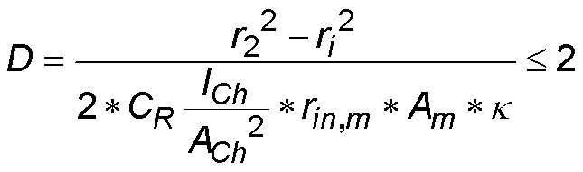
- D
- ein Designfaktor ist,
- CR
- ein Geometriefaktor ist, der vom Querschnitt des Flusswiderstandkanals abhängt,
- ICh
- die Länge des Flusswiderstandskanals ist,
- ACh
- die Querschnittfläche des Flusswiderstandskanals ist,
- nin,m
- die radiale Entfernung zwischen dem radial inneren Abschnitt des porösen Mediums und dem Rotationszentrum ist,
- Am
- die Querschnittfläche des porösen Mediums senkrecht zu dem Fluss ist, und
- κ
- die Permeabilität des porösen Mediums ist.
- D
- is a design factor,
- C R
- is a geometry factor that depends on the cross section of the flow resistance channel,
- I Ch
- the length of the flow resistance channel is,
- A Ch
- is the cross-sectional area of the flow resistance channel,
- n in, m
- is the radial distance between the radially inner portion of the porous medium and the center of rotation,
- A m
- the cross-sectional area of the porous medium is perpendicular to the flow, and
- κ
- the permeability of the porous medium.
Beispiele der vorliegenden Offenbarung basieren auf der Erkenntnis, dass es durch geschicktes Ausnutzen der Vorteile eines zentrifugalen mikrofluidischen Systems möglich ist, einen Flüssigkeitsstrom durch ein poröses Medium kontrolliert zu leiten, so dass zumindest die Hälfte des Flüssigkeitsstroms durch das poröse Medium geleitet wird. Bei Beispielen kann der Flüssigkeitsstrom kontrolliert durch ein poröses Medium geleitet werden, ohne dass es zu einem Umfließen des porösen Mediums kommt. Dabei ist einer Fluidkammer, in der das poröse Medium ohne vollständige, bezüglich des Flusses seitliche Abdichtung angeordnet ist, eine Zufluss-Struktur vorgeschaltet, die den Zufluss derart begrenzt, dass der Zufluss maximal dem Doppelten der maximal möglichen Flussrate durch das poröse Medium entspricht. Dadurch wird erreicht, dass von dem auf den radial inneren Abschnitt des porösen Mediums treffenden Flüssigkeitsstrom zumindest die Hälfte durch das poröse Medium geleitet wird. Fluidikstrukturen, die die Zufluss-Struktur, die Fluidkammer und das poröse Medium aufweisen, können ferner ausgelegt werden, damit das Verhältnis der ersten Flussrate zu der maximal möglichen Flussrate durch das poröse Medium kleinere Werte annimmt, beispielsweise einen Wert von 1 oder darunter, wobei dann der gesamte Flüssigkeitsstrom durch das poröse Medium fließen kann. Examples of the present disclosure are based on the recognition that, by skillfully exploiting the advantages of a centrifugal microfluidic system, it is possible to controllably direct a fluid flow through a porous medium such that at least half of the fluid flow is passed through the porous medium. In examples, the liquid stream can be passed through a porous medium in a controlled manner, without the porous medium flowing around it. In this case, a fluid chamber in which the porous medium is arranged without complete, with respect to the flow side seal, upstream of an inflow structure that limits the inflow such that the inflow corresponds to a maximum of twice the maximum possible flow rate through the porous medium. It is thereby achieved that at least half of the fluid stream striking the radially inner portion of the porous medium is passed through the porous medium. Fluidic structures comprising the inflow structure, the fluid chamber, and the porous medium may be further designed so that the ratio of the first flow rate to the maximum possible flow rate through the porous medium assumes smaller values, for example, a value of 1 or less, and then the entire liquid flow can flow through the porous medium.
Beispiele der vorliegenden Offenbarung basieren auf der Erkenntnis, dass die Integration eines porösen Mediums in eine zentrifugale mikrofluidische Plattform leicht mit anderen Operationen auf derselben zentrifugalen mikrofluidischen Plattform kombiniert werden kann. Bei Beispielen kann eine Blutplasmaseparation mit anschließender Aliquotierung und anschließender Verdünnung und anschließendem Mischen mit Komponenten zur Durchführung eines anschließendem Lateralfluss-Immunoassays mit minimalem Handhabungsaufwand und exaktem Probenvolumen realisiert werden. Das poröse Medium wird aufgrund seines großen Oberflächen-zu-Volumen-Verhältnisses als Substrat für die Oberflächenanbindungsreaktion genutzt.Examples of the present disclosure are based on the recognition that the integration of a porous medium into a centrifugal microfluidic platform can be easily combined with other operations on the same centrifugal microfluidic platform. In examples, a blood plasma separation followed by aliquoting and subsequent dilution and subsequent mixing with components to perform a subsequent lateral flow immunoassay with minimal handling and sample volume can be realized. The porous medium is used as a substrate for the surface attachment reaction because of its high surface-to-volume ratio.
Figurenlistelist of figures
Beispiele der vorliegenden Offenbarung werden nachfolgend Bezug nehmend auf die beiliegenden Zeichnungen näher erläutert. Es zeigen:
-
1 eine schematische Darstellung eines Beispiels einer Vorrichtung zum Leiten einer Flüssigkeit durch ein poröses Medium; -
2 eine schematische Darstellung eines weiteren Beispiels einer Vorrichtung zum Leiten einer Flüssigkeit durch ein poröses Medium; -
3 eine schematische Draufsicht eines Beispiels von Fluidikstrukturen mit einem mäanderförmigen Flusswiderstandskanal; -
4 eine schematische Draufsicht eines Beispiels von Fluidikstrukturen mit einem geraden Flusswiderstandskanal; -
5 ein Diagramm, das eine Bypassmenge einer an dem porösen Medium vorbeifließenden Flüssigkeit abhängig von einem Designfaktor D zeigt; -
6 eine schematische Draufsicht auf ein Beispiel von Fluidikstrukturen, die mehrere Fluidkammern mit zugeordneten Zufluss-Strukturen aufweisen; -
7 eine schematische Draufsicht auf ein Beispiel von Fluidikstrukturen, die mehrere in eine Fluidkammer in Strömungsrichtung hintereinander angeordnete poröse Medien aufweisen; -
8 eine schematische Draufsicht auf ein Beispiel von Fluidikstrukturen mit einer Zufluss-Struktur, die einen Heber aufweist; -
9 eine schematische Draufsicht auf ein Beispiel von Fluidikstrukturen, die eine radial innere Aliquotierstruktur aufweisen; -
10 eine schematische Draufsicht auf ein Beispiel von Fluidikstrukturen, die eine radial äußere Aliquotierstruktur aufweisen; -
11 eine schematische Querschnittansicht eines Beispiels von Fluidikstrukturen mit einem an einer Decke einer Fluidkammer angeordneten porösen Medium; -
12A eine schematische Querschnittansicht eines Beispiels von Fluidikstrukturen mit einem an einem Boden einer Fluidkammer angeordneten porösen Medium; -
12B eine schematische perspektivische Ansicht der Fluidikstrukturen von12A ; und -
13A bis13D schematische Draufsichten von Beispielen von porösen Medien.
-
1 a schematic representation of an example of a device for passing a liquid through a porous medium; -
2 a schematic representation of another example of a device for passing a liquid through a porous medium; -
3 a schematic plan view of an example of fluidic structures with a meandering flow resistance channel; -
4 a schematic plan view of an example of fluidic structures with a straight flow resistance channel; -
5 a diagram showing a bypass amount of a liquid flowing past the porous medium depending on a design factor D; -
6 a schematic plan view of an example of fluidic structures having a plurality of fluid chambers with associated inflow structures; -
7 a schematic plan view of an example of fluidic structures having a plurality of in a fluid chamber in the flow direction successively arranged porous media; -
8th a schematic plan view of an example of fluidic structures with an inflow structure having a lift; -
9 a schematic plan view of an example of fluidic structures having a radially inner Aliquotierstruktur; -
10 a schematic plan view of an example of fluidic structures having a radially outer Aliquotierstruktur; -
11 a schematic cross-sectional view of an example of fluidic structures with a arranged on a ceiling of a fluid chamber porous medium; -
12A a schematic cross-sectional view of an example of fluidic structures with a arranged at a bottom of a fluid chamber porous medium; -
12B a schematic perspective view of the fluidic structures of12A ; and -
13A to13D schematic plan views of examples of porous media.
DETAILLIERTE BESCHREIBUNG DETAILED DESCRIPTION
Im Folgenden werden Beispiele der vorliegenden Offenbarung detailliert und unter Verwendung der beigefügten Zeichnungen beschrieben. Es sei darauf hingewiesen, dass gleiche Elemente oder Elemente, die die gleiche Funktionalität aufweisen, mit gleichen oder ähnlichen Bezugszeichen versehen sind, wobei eine wiederholte Beschreibung von Elementen, die mit dem gleichen oder ähnlichen Bezugszeichen versehen sind, typischerweise weggelassen wird. Insbesondere können gleiche oder ähnliche Elemente jeweils mit Bezugszeichen versehen sein, die eine gleiche Zahl mit einem unterschiedlichen oder keinem Kleinbuchstaben aufweisen. Beschreibungen von Elementen, die gleiche oder ähnliche Bezugszeichen aufweisen, sind gegeneinander austauschbar. In der folgenden Beschreibung werden viele Details beschrieben, um eine gründlichere Erklärung von Beispielen der Offenbarung zu liefern. Es ist jedoch für Fachleute offensichtlich, dass andere Beispiele ohne diese spezifischen Details implementiert werden können. Merkmale der unterschiedlichen beschriebenen Beispiele können miteinander kombiniert werden, es sei denn Merkmale einer entsprechenden Kombination schließen sich gegenseitig aus oder eine solche Kombination ist ausdrücklich ausgeschlossen.Hereinafter, examples of the present disclosure will be described in detail and using the attached drawings. It should be understood that like elements or elements having the same functionality are denoted by like or similar reference numerals, with a repeated description of elements having the same or similar reference numerals being typically omitted. In particular, the same or similar elements may each be provided with reference numerals having an equal number with a different or no lower case letter. Descriptions of elements having the same or similar reference numerals are interchangeable. In the following description, many details are set forth in order to provide a more thorough explanation of examples of the disclosure. However, it will be apparent to those skilled in the art that other examples may be implemented without these specific details. Features of the various examples described may be combined with each other unless features of a corresponding combination are mutually exclusive or such combination is expressly excluded.
Bevor Beispiele der vorliegenden Offenbarung näher erläutert werden, werden Definitionen einiger hierin verwendeter Begriffe angegeben.Before further illustrating examples of the present disclosure, definitions of some terms used herein will be given.
Fluidikmodul: Körper, in dem Fluidikstrukturen gebildet sind, wobei der Körper als Rotationskörper oder als Einsatz für einen Rotationskörper ausgebildet sein kann. Beispiele eines Fluidikmoduls sind zentrifugale Kartuschen in Form von zentrifugal mikrofluidischen Scheiben oder mikrofluidische Zentrifugenröhrchen.Fluidic module: body in which fluidic structures are formed, wherein the body may be formed as a body of revolution or as an insert for a body of revolution. Examples of a fluidic module are centrifugal cartridges in the form of centrifugal microfluidic disks or microfluidic centrifuge tubes.
Fluidikstrukturen: in einem Fluidikmodul gebildete Ausnehmungen, Hohlräume und Kanäle, die zur Handhabung von Flüssigkeiten ausgelegt sind. Zentrifugale Mikrofluidikstrukturen sind zur Handhabung von Flüssigkeiten im Femtoliter- bis Milliliter-Bereich in rotierenden Systemen ausgelegt.Fluidic Structures: recesses, cavities and channels formed in a fluidic module designed to handle fluids. Centrifugal microfluidic structures are designed to handle liquids in the femtoliter to milliliter range in rotating systems.
Hydrostatische Höhe: radiale Distanz zwischen zwei Punkten in einem zentrifugalen Fluidikmodul (zwischen denen sich Flüssigkeit einer zusammenhängenden Flüssigkeitsmenge befindet).Hydrostatic Altitude: Radial distance between two points in a centrifugal fluidic module (between which there is liquid of a continuous amount of liquid).
Hydrostatischer Druck: durch Zentrifugalkraft induzierte Druckdifferenz zwischen zwei Punkten aufgrund der zwischen ihnen liegenden hydrostatischen Höhe, der Dichte des Mediums und der Rotationsfrequenz.Hydrostatic pressure: Centrifugal force-induced pressure difference between two points due to the hydrostatic head between them, the density of the medium and the frequency of rotation.
Kapillarität: Verhalten von Flüssigkeiten bei Kontakt mit Kapillaren, z. B. engen Röhren oder in einem porösen Medium. Diese Effekte werden durch die Oberflächenspannung von Flüssigkeiten selbst und die Grenzflächenspannung zwischen Flüssigkeiten und der festen Oberfläche hervorgerufen.Capillarity: Behavior of liquids in contact with capillaries, eg. As narrow tubes or in a porous medium. These effects are caused by the surface tension of liquids themselves and the interfacial tension between liquids and the solid surface.
Viskose Dissipation: beim Fließen einer Flüssigkeit verlorene Energie in Form von thermischer Energie durch interne Scherkräfte.Viscous dissipation: energy lost in the flow of a liquid in the form of thermal energy due to internal shear forces.
Permeabilität: quantitative Größe für die Durchlässigkeit eines porösen Mediums für Gase oder Flüssigkeiten.Permeability: quantitative size for the permeability of a porous medium to gases or liquids.
Immunoassay: eine Methode der Bioanalytik, die die spezifische Antikörper-Antigen-Reaktion nutzt, um einen Analyten in einer flüssigen Phase nachzuweisen.Immunoassay: a bioanalytical method that uses the specific antibody-antigen reaction to detect an analyte in a liquid phase.
Inkubationszeit: Zeit, in der eine spezifische Reaktion ablaufen kann, um beispielsweise den Antigen-Antikörper-Komplex zu bilden.Incubation time: Time at which a specific reaction can take place to form, for example, the antigen-antibody complex.
Festphase: Oberfläche eines Feststoffes, die beispielsweise für eine separierende Adsorptionsreaktionen genutzt wird. Die Oberfläche kann mit Substanzen funktionalisiert sein.Solid phase: surface of a solid which is used, for example, for a separating adsorption reaction. The surface can be functionalized with substances.
Antikörper: ein Protein, das körperfremde Stoffe (Antigen) erkennt und spezifisch anbindet.Antibody: a protein that recognizes and specifically binds foreign substances (antigen).
Antigen: körperfremde Stoffe, die von Antikörpern erkannt und an die Antikörper spezifisch anbinden können.Antigen: exogenous substances that can be recognized by antibodies and specifically bind to the antibodies.
Analyt: eine Komponente, die sich in der Analysenprobe befindet und die nachgewiesen werden soll.Analyte: a component that is in the analytical sample and is to be detected.
Bypass: Flüssigkeitsstrom, der nicht dem gewünschten fluidischen Pfad folgt, beispielsweise Fluss über oder neben einem poröses Medium, anstelle durch das poröse Medium hindurch. Bypass: Liquid flow that does not follow the desired fluidic path, such as flow above or adjacent to a porous medium, rather than through the porous medium.
Dynamischer Bereich: das Verhältnis zwischen dem maximalen noch zu differenzierenden Signal und dem minimalen noch zu differenzierenden Signal (Detektionsgrenze).Dynamic range: the ratio between the maximum signal to be differentiated and the minimum signal to be differentiated (detection limit).
Immunchromatographischer Schnelltest (Lateral Flow Test): ein physikalischchemisches Trennverfahren, welches Dünnschichtchromatographie und biochemische Affinitätsreaktionen kombiniert. Ein Schnelltest zum Nachweis von Analyten in Form eines Teststreifens, der in der Regel aus Membranen besteht, die aufgrund ihrer Kapillarität die Analysenprobe durch den Teststreifen ziehen.Lateral Flow Test: a physico-chemical separation technique that combines thin-layer chromatography and biochemical affinity reactions. A rapid test for the detection of analytes in the form of a test strip, which usually consists of membranes which, due to their capillarity, pull the sample through the test strip.
Radial: wird hierin der Ausdruck radial verwendet, so ist jeweils radial bezüglich eines Rotationszentrums
Heber: unter einem Heber wird hierin ein Fluidkanal verstanden, der ein lokales radiales Minimum zwischen einem radial ansteigenden und einem radial abfallenden Kanalabschnitt aufweist.Lift: A lift is understood here to mean a fluid channel which has a local radial minimum between a radially rising and a radially sloping channel section.
Beispiele der vorliegenden Offenbarung beziehen sich auf eine Struktur sowie ein Verfahren zum Prozessieren einer oder mehrerer Flüssigkeiten durch ein poröses Medium unter Zentrifugation. Die Flussrichtung ist nach radial auswärts.Examples of the present disclosure relate to a structure and method for processing one or more liquids through a porous medium under centrifugation. The flow direction is radially outward.
Bei Beispielen weist die Zufluss-Struktur zumindest einen Flusswiderstandskanal und/oder zumindest eine Düse, und/oder zumindest ein poröses Medium und/oder zumindest eine Bead-Schüttung auf. Bei Beispielen mündet die Zufluss-Struktur in einem radialen Abstand
Die Zufluss-Struktur bietet dem Flüssigkeitsfluss einen Flusswiderstand, durch den der Flüssigkeitsfluss auf die erste Flussrate begrenzt wird. Die Zufluss-Struktur stellt somit ein Flusswiderstandselement dar, dessen Fluideinlass in eine Zufluss-Kammer (Kavität) münden kann und dessen Fluidauslass in die Fluidkammer mündet bzw. mit Fluidkammer fluidisch gekoppelt ist. Die Zufluss-Kammer kann fließend in das Flusswiderstandselement übergehen oder sogar Teil des Widerstandselements sein. Bei Beispielen kann das Flusswiderstandselement durch ein poröses Medium oder eine Bead-Schüttung in der Zufluss-Kammer gebildet sein. Bei Beispielen kann das Flusswiderstandselement durch eine Düse am Ausgange der Zufluss-Kammer gebildet sein. Bei Beispielen kann das Flusswiderstandselement durch einen Kanal gebildet sein, dessen Einlass in die Zufluss-Kammer mündet und dessen Auslass in die Fluidkammer mündet.The inflow structure provides fluid flow with a flow resistance that limits fluid flow to the first flow rate. The inflow structure thus represents a flow resistance element whose fluid inlet can open into an inflow chamber (cavity) and whose fluid outlet opens into the fluid chamber or is fluidically coupled to the fluid chamber. The inflow chamber may flow smoothly into the flow resistance element or even be part of the resistance element. In examples, the flow resistance element may be formed by a porous medium or a bead bed in the inflow chamber. In examples, the flow resistance element may be formed by a nozzle at the exit of the inflow chamber. In examples, the flow resistance element may be formed by a channel whose inlet opens into the inflow chamber and whose outlet opens into the fluid chamber.
Bei Beispielen kann der Druckverlust pro Volumenstrom für die Definition eines Widerstandselementes angegeben werden. Ein Element kann dann als Widerstandselement für die Fluidikstruktur zählen, wenn gilt:
![]()
- R:
- fluidischer Widerstand des Elements,
- Δp:
- Druckverlust über dem Element,
- Q:
- Flussrate durch das Element.
- R:
- fluidic resistance of the element,
- Ap:
- Pressure loss over the element,
- Q:
- Flow rate through the element.
Wenn das Widerstandselement durch einen Flusswiderstandskanal gebildet ist, kann jeder Abschnitt einer Fluidstruktur als Teil eines Flusswiderstandskanals betrachtet werden, für dessen Flussquerschnitt ACh gilt:
![]()
![]()
Anders ausgedrückt kann jeder Teil einer Fluidstruktur, der einen Flussquerschnitt von weniger als 0,1 mm2 bietet, als ein Bestandteil eines Flusswiderstandskanals betrachtet werden.In other words, any part of a fluid structure that provides a flow area of less than 0.1 mm 2 may be considered as part of a flow resistance channel.
Wie im Folgenden ausführlich erläutert wird, sind gemäß der vorliegenden Offenbarung die Fluidikstrukturen derart ausgebildet, dass die folgende Gleichung erfüllt ist:
![]()
![]()
Qmax,m kann über das Darcy-Gesetz berechnet werden und gibt den maximal möglichen Fluss durch das poröse Medium, bei einem angelegten Zentrifugaldruck, ohne Bypass wieder. QCh wird je nach eingesetzten Widerstandselement berechnet oder experimentell eingestellt. Ist das Widerstandselement ein Kanal oder eine Düse kann der Druckverlust analog zum Hagen-Poiseuille-Gesetz berechnet werden. Hinsichtlich der Berechnung des Druckverlustes kann beispielsweise auf
Da beide Gesetze sich von den Navier-Stokes-Gleichungen ableiten und sich nur durch Parameter unterscheiden, die die jeweilige Geometrie des durchflossenen Elements berücksichtigen, kürzt sich bei der Berechnung des Verhältnisses der Flussraten die Viskosität der Flüssigkeit heraus. Beide Flüsse QCh und Qmax,m sind zentrifugal getrieben. Daher kürzt sich die Winkelgeschwindigkeit und Dichte ebenfalls bei der Berechnung des Verhältnisses der Flussraten heraus. Somit können die Fluidikstrukturen unabhängig von den Fluideigenschaften und der Rotationsfrequenz ausgelegt werden.Since both laws derive from the Navier-Stokes equations and differ only in parameters that take into account the particular geometry of the element being traversed, the viscosity of the liquid is reduced when calculating the ratio of the flow rates. Both flows Q Ch and Q max, m are centrifugally driven. Therefore, the angular velocity and density are also shortened in the calculation of the ratio of the flow rates. Thus, the fluidic structures can be designed independently of the fluid properties and the rotational frequency.
Falls erforderlich, kann die Flussrate durch die Zufluss-Struktur unter Verwendung der geometrischen Parameter der Zufluss-Struktur, der Rotationsgeschwindigkeit und der Fluideigenschaften der Flüssigkeit berechnet werden. Alternativ kann die Flussrate auch gemessen werden, indem das Flüssigkeitsvolumen erfasst wird, das in einer bestimmten Zeit durch die Zufluss-Struktur gelangt. Die maximal mögliche Flussrate durch das poröse Medium kann, bei Bedarf, ebenfalls unter Verwendung der Parameter des porösen Mediums und der Flüssigkeit berechnet werden oder kann experimentell ermittelt werden. If necessary, the flow rate through the inflow structure can be calculated using the geometric parameters of the inflow structure, the rate of rotation and the fluid properties of the liquid. Alternatively, the flow rate can also be measured by detecting the volume of liquid which passes through the inflow structure in a certain time. The maximum possible flow rate through the porous medium may also be calculated, if necessary, using the parameters of the porous medium and the liquid, or may be determined experimentally.
Das Fluidikmodul
Bei Beispielen der vorliegenden Offenbarung kann das Fluidikmodul aus einem beliebigen geeigneten Material gebildet sein, beispielsweise einem Kunststoff, wie PMMA (Polymethylmethacrylat), PC (Polycarbonat), PVC (Polyvinylchlorid) oder PDMS (Polydimethylsiloxan), Glas oder dergleichen. Der Rotationskörper
Bei Beispielen kann die Vorrichtung ferner eine Temperierungseinrichtung
Im Folgenden werden Beispiele der vorliegenden Offenbarung insbesondere anhand eines Flusswiderstandskanals als Zufluss-Struktur beschrieben. Die folgenden Lehren sind in gleicher Weise auf andere Widerstandselemente übertragbar.Hereinafter, examples of the present disclosure will be described specifically with reference to a flow resistance channel as an inflow structure. The following teachings are equally applicable to other resistor elements.
Bei Beispielen wird Flüssigkeit zentrifugal aus einer ersten Kammer durch einen Flusswiderstandskanal auf ein poröses Medium in einer zweiten Kammer getrieben. Die Flüssigkeit benetzt das poröse Medium, zum Beispiel eine Membran. Die Membran wird mit Flüssigkeit aufgefüllt und es entsteht ein Zentrifugaldruck in der Flüssigkeit in der Membran. Unter einem kritischen Füllstand hält die Kapillarkraft die Flüssigkeit in der Membran. Über einem kritischen Füllstand, gegebenenfalls auch komplett gefüllt, tritt Flüssigkeit radial außen aus der Membran aus. Dabei wird die Flussrate durch den Flusswiderstandskanal derart eingestellt, dass es zu nur bis zu einem bestimmten Grad oder zu keinem Umfließen der Flüssigkeit über oder neben dem porösen Medium kommt.In examples, fluid is centrifugally driven from a first chamber through a flow resistance channel to a porous medium in a second chamber. The liquid wets the porous medium, for example a membrane. The membrane is filled with liquid and there is a centrifugal pressure in the liquid in the membrane. Below a critical level, the capillary force holds the liquid in the membrane. Above a critical level, possibly also completely filled, liquid exits radially outward from the membrane. In this case, the flow rate through the flow resistance channel is set so that it comes only to a certain degree or to no flow around the liquid above or next to the porous medium.
Damit kann, vorausgesetzt die Flüssigkeit benetzt das poröse Medium, ein von der Kapillarkraft unabhängiger und gut kontrollierbarer Durchfluss durch ein poröses Medium realisiert werden. Bislang war die Verhinderung des Überfließens des porösen Mediums bei von radial innen nach radial außen getriebenen Flüssigkeiten nur über Strukturen möglich, die ein Umfließen des porösen Mediums durch eine physikalische Barriere verhindern und somit eine Dichtvorrichtung darstellen. Durch die vorliegende Offenbarung entfällt die Notwendigkeit einer Dichtvorrichtung. Es lässt sich die Flussrate und somit auch die Verweilzeit der Analysenproben im porösen Medium über einen weiten Arbeitsbereich präzise einstellen.Thus, provided that the liquid wets the porous medium, an independent of the capillary force and easily controllable flow through a porous medium can be realized. So far, the prevention of the overflow of the porous medium in fluids driven radially inward to radially outward was only possible via structures which prevent the porous medium from flowing around through a physical barrier and thus constitute a sealing device. The present disclosure eliminates the need for a sealing device. The flow rate and thus also the residence time of the analysis samples in the porous medium can be set precisely over a wide operating range.
Der Flusswiderstandskanal
Bei einem weiteren Beispiel der vorliegenden Offenbarung kann dabei der fluidische Widerstand des Flusswiderstandskanals
Wie in
Nachdem die Flüssigkeit das poröse Medium
Bei Beispielen der vorliegenden Offenbarung erfolgt bei einer Drehung des Fluidikmoduls um das Rotationszentrum
Damit das poröse Medium 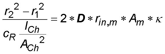
- r1:
- radial innen liegende Position der Flüssigkeitssäule bei 80% des initialen Füllvolumens
- r2:
- radial außen liegende Position der Flüssigkeitssäule
- CR:
- Geometriefaktor zur Berechnung des fluidischen Widerstands im Flusswiderstandskanal
- ICh:
- Länge des Flusswiderstandskanals
- ACh:
- Querschnittfläche des Flusswiderstandskanals
- D:
- Designfaktor
- rin,m:
- radiale Entfernung zwischen Rotationszentrum
R und radial innerem Ende des porösen Mediums - Am:
- Querschnittfläche des porösen Mediums
- κ:
- Permeabilität des porösen Mediums
- r 1 :
- radially inward position of the liquid column at 80% of the initial fill volume
- r 2 :
- radially outward position of the liquid column
- C R :
- Geometry factor for calculating the fluidic resistance in the flow resistance channel
- I Ch :
- Length of the flow resistance channel
- A Ch :
- Cross sectional area of the flow resistance channel
- D:
- design factor
- r in, m :
- radial distance between center of rotation
R and radially inner end of the porous medium - A m :
- Cross-sectional area of the porous medium
- κ:
- Permeability of the porous medium
Der Geometriefaktor 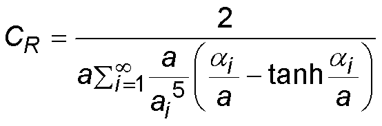
![]()
![]()
Dabei stellt
Gleichung (1) leitet sich aus folgenden physikalischen Gleichungen ab:
- Der Gleichung für den zentrifugalen Druck pcent im Flusswiderstandskanal:

- ω:
- Rotationsgeschwindigkeit
- ρ:
- Dichte des Fluids
- The equation for the centrifugal pressure p cent in the flow resistance channel:
- ω:
- rotation speed
- ρ:
- Density of the fluid
Der Gleichung für den hydrostatischen Druck in der Flüssigkeit im porösen Medium:
![]()
![]()
Der Gleichung für die viskose Dissipation im Flusswiderstandskanal:
![]()
- QCh:
- Flussrate durch den Flusswiderstandskanal
- η:
- Viskosität der Flüssigkeit
- Q Ch :
- Flow rate through the flow resistance channel
- η:
- Viscosity of the liquid
Der Darcy-Gleichung für die viskose Dissipation im porösen Medium:
![]()
![]()
Für die Berechnung wird ein gefülltes poröses Medium angenommen. Damit benötigt die Kapillarkraft keine Berücksichtigung. Die maximale bypassfreie Flussrate durch das poröse Medium Qmax,m wird bestimmt, indem der hydrostatische Druck in der Flüssigkeit im porösen Medium mit der viskosen Dissipation aufgrund des Durchflusses durch das poröse Medium gleichgesetzt wird:
![]()
![]()
Da der hydrostatische Druck in der Flüssigkeit im porösen Medium quadratisch, der Druckverlust durch viskose Dissipation linear über die radiale Länge des porösen Mediums zunimmt, werden beide Gleichungen nach der radialen Länge der Membran Im abgeleitet und im Punkt Im=0 gleichgesetzt. Damit ist sichergestellt, dass der Zentrifugaldruck über die gesamte Länge des porösen Mediums größer gleich der viskosen Dissipation ist.
![]()
![]()
![]()
![]()
![]()
![]()
Löst man Gleichung (8) nach Qmax,m auf, kann der maximal mögliche Durchfluss über die gesamte radiale Länge des porösen Mediums berechnet werden. Die entsprechende Gleichung für den maximal möglichen Durchfluss durch das poröse Medium lautet wie folgt:
![]()
![]()
Die Flussrate, die durch den Flusswiderstandskanal erzielt wird, berechnet sich wie folgt:
![]()
![]()
Durch Einsetzten von Gleichung (3) und Gleichung (5) in Gleichung (10) und Auflösen nach der Flussrate QCh im Kanal erhält man:

Um einen kompletten Durchfluss durch das poröse Medium zu gewährleisten, muss gelten:
![]()
![]()
Durch Gleichsetzen der beiden Flussraten Qmax,m und QCh wird der Umschlagspunkt definiert. Am Umschlagspunkt ist der Zentrifugaldruck der Flüssigkeitssäule im porösen Medium gleich der viskosen Dissipation im porösen Medium, die durch die vom Verbindungskanal vorgegebene Flussrate und einen theoretisch kompletten Durchfluss durch das poröse Medium auftritt. Wäre nun bei gleichbleibender Flussrate der Zentrifugaldruck kleiner, würde es zu einem Umfließen des porösen Mediums kommen.By equating the two flow rates Q max, m and Q Ch , the turnover point is defined. At the transition point, the centrifugal pressure of the liquid column in the porous medium is equal to the viscous dissipation in the porous medium, which occurs due to the flow rate predetermined by the connection channel and a theoretically complete flow through the porous medium. If the centrifugal pressure were smaller at a constant flow rate, the porous medium would flow around.
Ein zusätzlicher, definierter Designfaktor ![]()
![]()
Durch Auflösen von Gleichung (13) nach D erhält man:
![]()
![]()
Bei Beispielen der vorliegenden Offenbarung, wird die Fluidikstruktur als funktionierend betrachtet, wenn mindestens die Hälfte der zu prozessierenden Flüssigkeit durch das poröse Medium fließt. Daraus ergibt sich, dass ein Designfaktor
Durch Einsetzen von Gleichung (9) und Gleichung (11) in Gleichung (13) erhält man die obige Gleichung (1) zur Auslegung der Struktur.By substituting equation (9) and equation (11) into equation (13), the above equation (1) is obtained to design the structure.
Löst man Gleichung (1) nach 
In Tabelle 1 sind typische Größen für den Arbeitsbereich eines Fluidikmoduls aufgelistet, das nach Gleichung (16) ausgelegt wurde.
Bei den obigen Berechnungen geht die radiale Position
Bei Beispielen können die Fluidikstrukturen derart ausgelegt sein, dass ein größerer Anteil der Auftragsmenge das poröse Medium durchfließt. Bei Beispielen kann der Designfaktor
Bei Beispielen weist das Fluidikmodul eine Mehrzahl von Fluidkammern, in denen jeweils ein poröses Medium angeordnet ist, und eine jeder Fluidkammer zugeordnete Zufluss-Struktur auf, so dass gleichzeitig Flüssigkeit durch mehrere poröse Medien geleitet werden kann. Die Zufluss-Strukturen können die Flüsse auf gleiche Flussraten begrenzen oder können die Flüsse auf unterschiedliche Flussraten begrenzen, so dass die Flüssigkeit mit unterschiedlichen Flussraten unterschiedliche poröse Medien passiert. In examples, the fluidic module has a plurality of fluid chambers, in each of which a porous medium is arranged, and an inflow structure associated with each fluid chamber, so that at the same time fluid can be passed through a plurality of porous media. The inflow structures may confine the flows to equal flow rates or may limit the flows to different flow rates such that the liquid at different flow rates passes through different porous media.
Bei Beispielen können somit Fluidikstrukturen des Fluidikmoduls zur Integration eines porösen Mediums parallel betrieben werden. Ein Beispiel solcher Fluidikstrukturen ist in
Bei Beispielen sind mehrere poröse Medien radial nach außen hintereinander in der Fluidkammer angeordnet. Ein solches Beispiel ist in
Bei Beispielen weist die Zufluss-Struktur einen Flusswiderstandskanal auf, der einen Heber mit einem radial ansteigenden Kanalabschnitt und einem dem radial ansteigenden Kanalabschnitt nachgeschalteten radial abfallenden Kanalabschnitt aufweist. Bei solchen Beispielen kann der Flusswiderstandskanal zwischen einer ersten und einer zweiten Fluidkammer zum Weiterschalten der Flüssigkeit benutzt werden. Beispielsweise zeigt
Bei Beispielen weist das Fluidikmodul eine Aliquotierstruktur auf, die eine Mehrzahl von Ausgängen aufweist. Die Aliquotierstruktur liefert an jedem Ausgang ein Aliquot der Flüssigkeit. Jeder Ausgang der Aliquotierstruktur ist mit einer anderen einer Mehrzahl von Aliquot-Kammern fluidisch gekoppelt. Jede einer Mehrzahl von Fluidkammern ist über eine zugehörige Zufluss-Struktur mit einer unterschiedlichen Aliquot-Kammer fluidisch verbunden.In examples, the fluidic module has an aliquoting structure having a plurality of outputs. The aliquoting structure provides an aliquot of the liquid at each outlet. Each output of the aliquoting structure is fluidically coupled to another of a plurality of aliquot chambers. Each of a plurality of fluid chambers is fluidly connected to a different aliquot chamber via an associated inflow structure.
Die
Wie in
Gemäß
Bei Beispielen ist das poröse Medium an einer Kammerwand der Fluidkammer fixiert und mit einem Abstand von zumindest einer weiteren Kammerwand der Fluidkammer angeordnet, so dass ein Bypass-Pfad existiert. Bei Beispielen ist das poröse Medium an einer Decke der Fluidkammer fixiert. Bei Beispielen ist das poröse Medium an einem Boden der Fluidkammer fixiert. Bei Beispielen sind in der Fluidkammer Führungsstrukturen vorgesehen sind, um die Flüssigkeit zu dem radial inneren Abschnitt des porösen Mediums zu leiten. Bei Beispielen kann die Führungsstruktur eine Einkerbung am Übergang von der Zufluss-Struktur in die Fluidkammer aufweisen, die ausgelegt ist, um die Flüssigkeit mit Hilfe von Kräften, die aus der Oberflächenspannung der zu leitenden Flüssigkeit resultieren, zu dem radial inneren Abschnitt des porösen Mediums zu leiten.In examples, the porous medium is fixed to a chamber wall of the fluid chamber and spaced apart from at least one other chamber wall of the fluid chamber such that a bypass path exists. In examples, the porous medium is fixed to a ceiling of the fluid chamber. In examples, the porous medium is fixed to a bottom of the fluid chamber. In examples, guide structures are provided in the fluid chamber for directing the fluid to the radially inner portion of the porous medium. In examples, the guide structure may include a notch at the transition from the inflow structure into the fluid chamber configured to deliver the liquid to the radially inner portion of the porous medium by means of forces resulting from the surface tension of the liquid to be conducted conduct.
Es sei angemerkt, dass bei den beschriebenen Mikrofluidikstrukturen Gravitationskräfte gegenüber Kapillarkräften und Zentrifugalkräften vernachlässigbar sind.It should be noted that in the described microfluidic structures gravitational forces are negligible with respect to capillary forces and centrifugal forces.
Bei Beispielen weist der radial innere Rand des porösen Medium eine Einkerbung mit einer Einkerbungskante auf, die zu bezüglich des Flusses seitlichen Rändern des porösen Mediums hin radial ansteigt. Der radial innere Bereich des porösen Mediums, auf den die Flüssigkeit trifft, befindet sich zwischen den seitlichen Rändern des porösen Mediums, zu denen hin die Einkerbungskante radial ansteigt. Die radial innen liegende Einkerbung des porösen Mediums zur Umfließungsvermeidung kann bei Beispielen unterschiedliche Geometrien aufweisen. Vier mögliche Varianten sind in den
Bei Beispielen der vorliegenden Offenbarung sind die Fluidikstrukturen derart ausgelegt, dass der Flüssigkeitsstrom aus der Zufluss-Struktur mittig oder im Wesentlichen mittig auf den radial inneren Abschnitt des porösen Mediums trifft. Bei Beispielen sind die Fluidikstrukturen derart ausgebildet, dass der Flüssigkeitsstrom mittig oder im Wesentlichen mittig auf die Einkerbung trifft. Bei Beispielen kann die Zufluss-Struktur radial innerhalb des radial inneren Abschnitts des porösen Mediums angeordnet sein und demselben gegenüberliegen, um den Flüssigkeitsstrom auf diesen Abschnitt zu richten. In examples of the present disclosure, the fluidic structures are configured such that the liquid flow from the inflow structure meets centrally or substantially centrally of the radially inner portion of the porous medium. In examples, the fluidic structures are designed such that the liquid flow hits the notch centrally or substantially in the middle. In examples, the inflow structure may be located radially inward of and opposite the radially inner portion of the porous media to direct fluid flow to that portion.
Bei Beispielen der vorliegenden Offenbarung enthält die Flüssigkeit, die durch das poröse Medium geleitet wird, einen Reaktionsmix für eine (bio-)chemische Interaktion am porösen Medium. Diese Reaktion kann beispielsweise für eine (bio-)chemische Umsetzung oder auch zur Detektion von Biomolekülen geeignet sein, wie z.B. Goldnanopartikel oder Fluoreszenzpartikel mit immobilisierten Antikörpern. Überdies kann die Flüssigkeit einen Analyten enthalten, der nachgewiesen werden soll. Zusätzlich kann das poröse Medium mit Biomolekülen imprägniert sein, beispielsweise Fängerantikörpern, an welche Substanzen aus der Flüssigkeit anbinden können.In examples of the present disclosure, the liquid passed through the porous medium contains a reaction mix for a (bio) chemical interaction on the porous medium. This reaction may be suitable, for example, for a (bio) chemical reaction or also for the detection of biomolecules, such as e.g. Gold nanoparticles or fluorescent particles with immobilized antibodies. Moreover, the liquid may contain an analyte to be detected. In addition, the porous medium may be impregnated with biomolecules, for example capture antibodies, to which substances can attach from the liquid.
Bei Beispielen stellt das poröse Medium eine Festphase für Oberflächenreaktionen dar, wobei das poröse Medium mit einem reaktiven Komponenten, wie z.B. Biomolekülen, imprägniert sein kann. Bei Beispielen stellt das poröse Medium eine Festphase für Oberflächenanbindungsreaktionen dar.In examples, the porous medium is a solid phase for surface reactions wherein the porous medium is reacted with a reactive component, e.g. Biomolecules, can be impregnated. In examples, the porous medium is a solid phase for surface attachment reactions.
Bei Beispielen kann ein optisches Auslesesystem vorgesehen sein, um das Ergebnis der Reaktion auszulesen. Hierzu können Teile des Fluidikmoduls und des Systems transparent sein, um ein optisches Auslesen durch solche Teile zu ermöglichen. Zusätzlich kann bei Beispielen eine Temperierungseinrichtung vorgesehen sein, um die Temperatur des Fluidikmoduls bei Bedarf während des kompletten Prozesses kontrolliert einzustellen. Dies ermöglicht es beispielsweise, gleiche Anbindungsraten der Substanzen Fluidikmodul-übergreifend zu realisieren.In examples, an optical readout system may be provided to read the result of the reaction. For this purpose, parts of the fluidic module and the system may be transparent in order to enable optical reading through such parts. In addition, in examples, a tempering device may be provided to adjust the temperature of the fluidic module as needed during the entire process. This makes it possible, for example, to realize the same connection rates of the substances across fluidic modules.
Bei Beispielen der vorliegenden Offenbarung wird somit eine laterale Bewegung einer flüssigen Probe oder einer flüssigen Reagenzie entlang eines porösen Mediums, das auch als poröse Trägermatrix bezeichnet werden kann, nach radial auswärts bewirkt, indem die flüssige Probe durch Drehen des Fluidikmoduls mit einer Zentrifugalkraft beaufschlagt wird. Dadurch ermöglichen Beispiele der vorliegenden Offenbarung die Durchführung eines Lateralfluss-Immunoassays. Das poröse Medium kann eine offenporige Struktur mit einer mittleren Porengröße im Bereich von 0.05 bis 250 Mikrometern und eine Dicke in einem Bereich von 0,01 bis 5 mm aufweisen. Das poröse Material kann ein offenporiges gesintertes Material, offenporiges Polymer, offenporiges Keramikmaterial, offenporigen polymeren Schaum, offenporigen Verbundwerkstoff, Natur- oder Kunstfaserstoff, eine vernetzte Beadschüttung oder Nitrocellulose aufweisen.Thus, in examples of the present disclosure, lateral movement of a liquid sample or reagent past a porous medium, which may also be referred to as a porous support matrix, is effected radially outward by imparting a centrifugal force to the liquid sample by rotation of the fluidic module. As a result, examples of the present disclosure permit the performance of a lateral flow immunoassay. The porous medium may have an open-pore structure with an average pore size in the range of 0.05 to 250 micrometers and a thickness in the range of 0.01 to 5 mm. The porous material may comprise an open celled sintered material, open celled polymer, open celled ceramic, open celled polymeric foam, open celled composite, natural or synthetic pulp, cross-linked bead fill or nitrocellulose.
Es wurde erkannt, dass durch Beispiele der vorliegenden Offenbarung zahlreiche Nachteile, die bei den eingangs beschriebenen bekannten Systemen, die eine Flusskontrolle durch ein poröses Medium bieten, auftreten, reduzieren oder beseitigt werden können, von denen im Folgenden einige genannt werden. Bei bekannten Systemen ist die Flussrate abhängig von der Kapillarität des porösen Mediums und damit werden die dort beschriebenen Verfahren immer durch die begrenzt veränderbaren Eigenschaften des porösen Mediums eingeschränkt. Die maximal mögliche Flussrate ist bei einem Fluss nach radial einwärts durch die Kapillarkraft begrenzt, da die Zentrifugalkraft den Fluss nur abbremsen kann und nicht beschleunigen kann. Hochviskose Medien, die sehr langsam durch das poröse Medium gezogen werden, können deshalb nur begrenzt prozessiert werden, da eine Flussratenbeschleunigung benötigt wird, verglichen mit dem rein kapillaren Fluss, um die für den Test benötigte Zeit anwenderfreundlich zu verkürzen. Die Flussrate ist abhängig von der bereits aufgestiegenen Flüssigkeitssäule im porösen Medium und damit zeitabhängig bei konstanter Rotationsfrequenz. Das zu prozessierende Flüssigkeitsvolumen ist durch die Aufnahmekapazität des porösen Mediums begrenzt. Durch das Einbringen eines sogenannten Waste-Vlieses kann die Aufnahmekapazität zwar erhöht werden, das Vlies benötigt jedoch zusätzlichen Platz und die Verbindung zwischen dem porösen Medium und dem Waste-Vlies ist eine zusätzliche Quelle für Flussratenvariationen zwischen den Fluidikmodulen. Die in der
Im Gegensatz zu den bekannten Techniken kann vermittels der beschriebenen Strukturen gemäß Beispielen der vorliegenden Offenbarung auf dem Gebiet der zentrifugalen Mikrofluidik ein, vorausgesetzt die Flüssigkeit benetzt das poröse Medium, Kapillarkraftunabhängiger, total kontrollierbarer und kompletter (oder abhängig von der Wahl des Designfaktors D zumindest mehr als 50-prozentiger) Durchfluss durch ein poröses Medium erzielt werden. Für die Integration des porösen Mediums in die Struktur wird keine Dichtvorrichtung benötigt. Das poröse Medium kann auf einfache Weise an der Decke oder dem Boden einer Fluidkammer fixiert werden. Es lässt sich die Flussrate und somit auch die Verweilzeit der Analysenprobe im porösen Medium präzise über die Auslegung des durchflussbegrenzenden Flusswiderstandskanals und die Rotationsfrequenz einstellen, unabhängig von der Herstellungsgüte des porösen Mediums.In contrast to the known techniques, by means of the described structures according to examples of the present disclosure in the field of centrifugal microfluidics, provided that the liquid wets the porous medium, capillary force more independent, totally controllable and complete (or at least more depending on the choice of
Damit kann die Inkubationszeit nicht nur verlängert, sondern auch verkürzt werden, verglichen mit einem kapillar getriebenen Durchfluss. Damit ist es erstmals mit dem Fluidikmodul der vorliegenden Offenbarung möglich, größere Probenvolumina einer viskosen Probe in einem sinnvollen Zeitrahmen kontrolliert zu prozessieren. Eine notwendige Verdünnung der Analysenprobe zur Viskositätserniedrigung ist gegebenenfalls nicht mehr notwendig. Diese Möglichkeit basiert insbesondere auf drei Faktoren, die generelle Vorteile gegenüber anderen Systemen darstellen:
- - Die fluidische Weglänge durch das poröse Medium bleibt nach der Initialbefüllung des porösen Mediums mit der zu prozessierenden Flüssigkeit konstant, da keine weiteren Vliese, wie beispielsweise ein Waste-Vlies, benötigt werden und somit nicht vorgesehen sind.
- - Die fluidische Weglänge durch das poröse Medium hat keinen Einfluss auf die Flussrate und kann daher beliebig kurz bzw. lang gewählt werden.
- - Die antreibende Kraft des Durchflusses ist allein die Zentrifugalkraft. Dementsprechend kann durch eine Steigerung des zentrifugalen Drucks in der Flüssigkeit im porösen Medium die viskose Flüssigkeit mit Inkubationszeiten prozessiert werden, die vergleichbar mit denen niederviskoser Flüssigkeiten wären.
- - The fluidic path length through the porous medium remains constant after the initial filling of the porous medium with the liquid to be processed, since no further nonwovens, such as a nonwoven Waste, are needed and thus are not provided.
- - The fluidic path length through the porous medium has no influence on the flow rate and can therefore be chosen as short or long as desired.
- - The driving force of the flow is the centrifugal force alone. Accordingly, by increasing the centrifugal pressure in the liquid in the porous medium, the viscous liquid can be processed with incubation times comparable to those of low-viscosity liquids.
Ferner ermöglichen es Beispiele der vorliegenden Offenbarung, Viskositätsschwankungen zwischen den Analysenproben durch eine vorausgehende Viskositätsmessung (intern in der Disk oder extern im Labor) mit anschließender Rotationsfrequenzanpassung auszugleichen, was zu testübergreifend, gleichbleibenden Inkubationszeiten führt.Further, examples of the present disclosure allow for viscosity variations between the analytical samples to be compensated for by a prior viscosity measurement (internally in the disk or externally in the laboratory) followed by rotational frequency adjustment resulting in consistent, incubation times across tests.
Beispiele der vorliegenden Offenbarung weisen eine Einrichtung zum Erfassen einer Information über die Viskosität der Flüssigkeit auf, wobei die Vorrichtung ausgelegt ist, um die Drehgeschwindigkeit der Drehung abhängig von der erfassten Information über die Viskosität einzustellen, um die Flussrate durch den Zufluss-Kanal einzustellen. Gemäß der vorliegenden Offenbarung ist die Strukturauslegung unabhängig von den Fluideigenschaften und der Rotationsfrequenz. Dies gilt jedoch nicht für die sich einstellende Flussrate. Diese ist abhängig von den Fluideigenschaften und der Rotationsfrequenz. So fließen beispielsweise hochviskose Fluide bei gleicher Frequenz langsamer durch das Fluidikmodul als niedrigviskose. Daher haben Viskositätsschwankungen der Flüssigkeitsprobe Einfluss auf die benötigte Prozessierzeit und damit auch auf die Verweilzeit der Biomoleküle in dem porösen Medium. Ist die Viskosität bekannt, beispielsweise durch eine experimentelle Bestimmung oder eine Messung auf dem Fluidikmodul, kann die Rotationsfrequenz angepasst werden, um eine Proben-unabhängige Flussrate zu erzielen, beispielsweise eine Flussrate von immer 0.05 µl/s unabhängig von der Viskosität. Somit kann beispielsweise der Variationskoeffizient eines Assays deutlich gesenkt werden.Examples of the present disclosure include means for acquiring fluid viscosity information, the apparatus being configured to adjust the rotational speed of rotation in response to sensed viscosity information to adjust the flow rate through the inflow channel. According to the present disclosure, the structural design is independent of the fluid properties and the rotational frequency. However, this does not apply to the self-adjusting flow rate. This depends on the fluid properties and the rotation frequency. For example, highly viscous fluids at the same frequency flow more slowly through the fluidic module as low viscosity. Therefore, viscosity fluctuations of the liquid sample have an influence on the required processing time and thus also on the residence time of the biomolecules in the porous medium. If the viscosity is known, for example by an experimental determination or a measurement on the fluidic module, the rotational frequency can be adjusted to achieve a sample-independent flow rate, for example a flow rate of always 0.05 μl / s regardless of the viscosity. Thus, for example, the coefficient of variation of an assay can be significantly reduced.
Davon können im speziellen Assays, die ein poröses Medium als Festphase nutzen, profitieren, wie zum Beispiel Lateralflussassays. Eine Sensitivitätssteigerung ist zu erwarten, zum einen da die Inkubationszeit von niederviskosen Analysenproben verlängert werden kann. Damit werden keine Reaktanten mit einer schnellen Reaktionskinetik mehr benötigt und die Auswahlmöglichkeiten der verwendbaren Reaktionspartner werden erheblich vergrößert. Zum anderen kann, im Gegensatz zu bekannten Verfahren, das Probenvolumen unabhängig von der Membrangröße gewählt werden, da kein Waste-Vlies benötigt wird, und das Probenvolumen nur durch die Auslegung der peripheren mikrofluidischen Struktur beschränkt ist. Des Weiteren können viskose Proben unverdünnt prozessiert werden. Beide Vorteile erhöhen die Wahrscheinlichkeit, dass ein niederkonzentrierter Analyt in der Probe auf der Oberfläche des porösen Mediums anbindet. Of these, in particular, assays that utilize a porous medium as a solid phase can benefit, such as lateral flow assays. An increase in sensitivity is to be expected, firstly because the incubation period of low-viscosity analysis samples can be extended. Thus, no reactants with a fast reaction kinetics longer needed and the choices of usable reactants are significantly increased. On the other hand, in contrast to known methods, the sample volume can be selected independently of the membrane size, since no waste fleece is needed, and the sample volume is limited only by the design of the peripheral microfluidic structure. Furthermore, viscous samples can be processed undiluted. Both advantages increase the likelihood that a low-concentration analyte will bind in the sample on the surface of the porous medium.
Ebenso ermöglichen Beispiele der vorliegenden Offenbarung, den Flüssigkeitsstrom erstmals durch Abbremsen auf eine Rotationsfrequenz von 0 Hz zu stoppen, da der Fluss durch das poröse Medium (die Membran) nicht kapillargetrieben ist. Damit kann ein kontinuierliches Auslesen während des gesamten Assays realisiert werden, was wiederum für eine Vergrößerung des dynamischen Bereichs des Assays genutzt werden kann, da bei hohen Analyt-Konzentrationen der Assay vorzeitig beendet werden könnte.Likewise, examples of the present disclosure allow the fluid flow to be stopped for the first time by decelerating to a rotational frequency of 0 Hz, since the flow through the porous medium (the membrane) is not capillary driven. Thus, a continuous readout can be realized throughout the assay, which in turn can be used to increase the dynamic range of the assay because at high analyte concentrations the assay could be prematurely terminated.
Überdies können unterschiedliche Flüssigkeiten ohne zusätzlichen Aufwand sequentiell durch das poröse Medium getrieben werden. Somit können beispielsweise Waschschritte zwischen oder nach den (bio-)chemischen Interaktionen am porösen Medium durchgeführt werden.Moreover, different liquids can be sequentially driven through the porous media without additional effort. Thus, for example, washing steps can be carried out between or after the (bio) chemical interactions on the porous medium.
Des Weiteren können insbesondere im Vergleich mit einem bekannten immunchromatographischen Schnelltest Reagenzien unter kontrollierten Bedingungen und in speziellen Mischkammern rehydriert werden, was die Wiederholgenauigkeit des Tests erhöht, verglichen mit der Rehydrierung aus einem Vlies unter einem kontinuierlichen Durchfluss. Ebenfalls kann die Wiederholgenauigkeit durch das Wegfallen weiterer Vliese (Proben- (Sample-), Konjugat- und Waste-Vlies) und damit auch das Wegfallen der Verbindungsflächen zwischen den Komponenten gesteigert werden.Furthermore, particularly in comparison with a known rapid immunochromatographic assay, reagents can be rehydrated under controlled conditions and in special mixing chambers, which increases the repeatability of the assay compared to the rehydration from a nonwoven under continuous flow. Likewise, the repetition accuracy can be increased by eliminating further nonwovens (sample, sample, conjugate and waste nonwoven) and thus also the elimination of the bonding surfaces between the components.
Ebenso kann verglichen mit einem Lateralfluss-Teststreifen das gesamte Probenvolumen über das poröse Medium gedrückt werden, sodass insgesamt weniger Probenvolumen und damit auch weniger Reagenzien für das gleiche Ergebnis benötigt werden, da keine Flüssigkeit in einem Proben-Pad zurückbleibt.Likewise, compared to a lateral flow test strip, the entire sample volume can be forced over the porous medium, so that less total sample volume and hence fewer reagents are required for the same result, since no liquid remains in a sample pad.
Ergänzend kann am Ende des Prozesses Flüssigkeit im porösen Medium leicht mechanisch getrocknet werden, beispielsweise durch ein Ausschleudern. Die Membran befüllt sich im Gegensatz zu bekannten Verfahren, bei denen ein kapillar getriebener Fluss in Richtung radial einwärts implementiert ist, nicht erneut, sondern bleibt ungefüllt, was einen konstanten Hintergrund für eine mögliche nachfolgende optische Auswertung bietet und mögliche Folgereaktionen der Biomoleküle auf dem porösen Medium unterbindet.In addition, at the end of the process, liquid in the porous medium can easily be dried mechanically, for example by ejection. The membrane does not refill, unlike known methods in which a capillary-driven flow is implemented radially inward, but remains unfilled, providing a constant background for possible subsequent optical evaluation and possible sequential reactions of the biomolecules on the porous medium in derogation.
Beispiele der vorliegenden Offenbarung bieten somit folgende Vorteile:
- • Vollständig kontrollierter Fluss einer das poröse Medium benetzenden Flüssigkeit durch das poröse Medium in Richtung radial außen bei geringen oder keinem Bypass ohne die Notwendigkeit einer Dichtvorrichtung.
- • Der Durchfluss ist entkoppelt von den Materialeigenschaften des porösen Mediums wie z. B. der Permeabilität und Kapillarkraft
- • Die Flussrate durch das poröse Medium wird nur über die Rotationsfrequenz und den durchflussbegrenzenden Flusswiderstandskanal gesteuert. Damit kann die Flussrate präzise auf ein konstantes Niveau eingestellt werden, was wiederum ein akkurates Einstellen der Inkubationszeiten ermöglicht
- • Die Auslegung des Fluidikmoduls zur Vermeidung von Bypassflüssen um ein integriertes, poröses Medium erfolgt unabhängig von Viskosität und Dichte der zu prozessierenden Flüssigkeit, sowie unabhängig von der genutzten Rotationsfrequenz
- • Das maximale Probenvolumen ist nicht durch die Aufnahmekapazität des porösen Mediums begrenzt und kann beliebig gewählt werden, es werden keine zusätzlichen porösen Medien (Sample-, Konjugat- und Waste-Pad) benötigt
- • Der Flüssigkeitsauftrag auf das poröse Medium kann zu jeder Zeit gestoppt werden, sodass im Stillstand eine Auslese des porösen Mediums durchgeführt werden kann
- • Unterschiedliche Flüssigkeiten können ohne zusätzlichen Aufwand sequentiell durch das poröse Medium getrieben werden, beispielsweise zur Realisierung von Waschschritten
- • Das poröse Medium kann mechanisch getrocknet werden (Ausschleudern), was einen homogenen Hintergrund bei einer optischen Auslese ergibt, sowie Folgereaktionen im porösen Medium unterbindet.
- Completely controlled flow of liquid wetting the porous medium through the porous medium in a radially outward direction with little or no bypass without the need for a sealing device.
- • The flow is decoupled from the material properties of the porous medium such. B. the permeability and capillary force
- • The flow rate through the porous medium is controlled only by the rotation frequency and flow restricting flow resistance channel. Thus, the flow rate can be precisely adjusted to a constant level, which in turn allows accurate setting of the incubation times
- • The design of the fluidic module to avoid bypass flows around an integrated, porous medium is independent of the viscosity and density of the liquid to be processed, as well as independent of the rotational frequency used
- • The maximum sample volume is not limited by the capacity of the porous medium and can be chosen arbitrarily, no additional porous media (sample, conjugate and waste pad) are required
- • The liquid application to the porous medium can be stopped at any time so that a readout of the porous medium can be carried out at standstill
- • Different liquids can be sequentially driven through the porous medium without additional effort, for example, for the realization of washing steps
- • The porous medium can be dried mechanically (ejection), which results in a homogeneous background in an optical read-out and prevents subsequent reactions in the porous medium.
Beispiele der vorliegenden Offenbarung schaffen ein Fluidikmodul für die zentrifugale Mikrofluidik, zum Befüllen, Durchfließen und Entleeren eines integrierten, freiliegenden porösen Mediums mit einer das poröse Medium benetzenden Flüssigkeit von radial innen nach radial außen, bestehend aus mindestens einer ersten Kammer, welche über mindestens einen Verbindungskanal mit mindestens einer zweiten Kammer verbunden ist. Die zweite Kammer beinhaltet mindestens ein poröses Medium. Der fluidische Widerstand des Verbindungskanals ist derart ausgestaltet, dass unter Zentrifugation die Flüssigkeit durch das poröse Medium fließt, wobei unter Rotation die resultierende Flussrate von der ersten Kammer in die zweite Kammer zu der folgenden Bedingung führt: Wenn der gesamte Fluss des Flusswiderstandskanals durch das poröse Medium von radial innen nach radial außen fließen würde, würde ein viskoser Druckverlust pDarcy resultieren, der maximal dem 2-fachen des hydrostatischen Drucks phyd,mem der Flüssigkeit im porösen Medium entspräche, wenn das poröse Medium über die gesamte radiale Länge mit Flüssigkeit gefüllt wäre. Bei einem solchen Fluidikmodul kann eine dem Flusswiderstandskanal nachfolgende Führungskanal-Struktur die Flüssigkeit auf das poröse Medium leiten. Das poröse Medium kann an der radial innen liegenden Position eingekerbt sein, wobei die Einkerbungskante an den Schnittpunkten mit den beiden radial verlaufenden Rändern des porösen Mediums in Richtung radial innen (Richtung Schnittpunkt) ansteigt. Die Struktur kann so ausgeführt sein, dass der Verbindungskanal zwischen der ersten und der zweiten Kammer als Heber ausgeführt ist. Eine vorgeschaltete Viskositätsmessung kann zur Rotationsfrequenzanpassung für die Prozessierung der Flüssigkeit genutzt werden. Die Flüssigkeit (wässrige Phase) kann einen Reaktionsmix für eine (bio-)chemische Interaktion am porösen Medium darstellen.Examples of the present disclosure provide a fluidic module for centrifugal microfluidics for filling, flowing, and discharging an integrated, exposed porous medium having a liquid wetting the porous medium from radially inward to radially outward, comprising at least a first chamber, which communicates via at least one communication channel is connected to at least one second chamber. The second chamber contains at least one porous medium. The fluidic resistance of the connection channel is designed such that, under centrifugation, the liquid flows through the porous medium, with rotation, the resulting flow rate from the first chamber into the second chamber leads to the following condition: When the entire flow of the flow resistance channel through the porous medium from radially inward to radially outward, a viscous pressure loss p Darcy would result, which would correspond at most to twice the hydrostatic pressure p hyd, mem of the liquid in the porous medium if the porous medium were filled with liquid over the entire radial length , In such a fluidic module, a guide channel structure following the flow resistance channel can direct the liquid to the porous medium. The porous medium may be notched at the radially inward position, wherein the notch edge at the intersections with the two radially extending edges of the porous medium in the direction radially inward increases (direction of intersection). The structure may be designed so that the connecting channel between the first and the second chamber is designed as a lifter. An upstream viscosity measurement can be used for rotational frequency adjustment for the processing of the liquid. The liquid (aqueous phase) can represent a reaction mix for a (bio) chemical interaction on the porous medium.
Beispiele der vorliegenden Offenbarung beziehen sich somit auf Fluidikmodule, Vorrichtungen und Verfahren, um Flüssigkeiten kontrolliert durch ein poröses Medium in Richtung radial auswärts zu treiben. Aufgabe der ist es dabei, bei minimalem Handhabungsaufwand den Fluss einer Flüssigkeit durch ein poröses Medium nach radial außen zu gewährleisten und ein Umfließen des porösen Mediums zu verhindern oder zu begrenzen, um damit die vollständige Kontrolle der Flussrate durch das poröse Medium zu erhalten. Ein kontinuierlicher Durchfluss durch ein poröses Medium nach radial auswärts bringt deutliche Vorteile mit sich, wurde jedoch bisher nach Veröffentlichungen und Expertenaussagen als unkontrollierbares und mit Bypass behaftetes Integrationskonzept angesehen.Examples of the present disclosure thus relate to fluidic modules, devices, and methods for driving fluids in a controlled manner radially outwardly through a porous medium. The object of this is to ensure the flow of a liquid through a porous medium radially outward with minimal handling effort and to prevent or limit the circulation of the porous medium in order to obtain complete control of the flow rate through the porous medium. A continuous flow through a porous medium radially outward brings significant advantages, but has so far been regarded, according to publications and expert statements, as an uncontrollable and bypassed integration concept.
Unter den Ausdruck Flüssigkeit bzw. flüssigen Phase, wie er hierin verwendet wird, fallen, wie Fachleuten offensichtlich ist, insbesondere auch Flüssigkeiten, die Feststoffbestandteile beinhalten, wie z.B. Suspensionen, biologische Proben und Reagenzien.As used herein, the term liquid or liquid phase, as will be apparent to those skilled in the art, includes, in particular, liquids containing solid components, such as e.g. Suspensions, biological samples and reagents.
Beispiele der vorliegenden Offenbarung können insbesondere auf dem Gebiet der zentrifugalen Mikrofluidik Anwendung finden, bei der es um die Prozessierung von Flüssigkeiten im Femtoliter- bis Milliliter-Bereich geht. Entsprechend können die Fluidikstrukturen geeignete Abmessungen im Mikrometerbereich für die Handhabung entsprechender Flüssigkeitsvolumina aufweisen. Insbesondere können Beispiele der Offenbarung auf zentrifugal-mikrofluidischen Systemen Anwendung finden, wie sie beispielsweise unter der Bezeichnung „Lab-on-a-Disk“ bekannt sind.Examples of the present disclosure may find particular application in the field of centrifugal microfluidics, which involves the processing of liquids in the femtoliter to milliliter range. Accordingly, the fluidic structures can have suitable dimensions in the micrometer range for handling corresponding volumes of liquid. In particular, examples of the disclosure may be applied to centrifugal microfluidic systems, such as those known by the name "Lab-on-a-Disk".
Allgemein können bei Beispielen der Offenbarung unterschiedliche Flusswiderstände (fluidische Widerstände, hydraulische Widerstände) jeweiliger Fluidkanäle über unterschiedliche Strömungsquerschnitte erreicht werden. Bei alternativen Beispielen können unterschiedliche Strömungswiderstände auch durch andere Mittel erreicht werden, beispielsweise unterschiedliche Kanallängen, in die Kanäle integrierte Hindernisse und dergleichen. Ist ein Vergleich zwischen Strömungswiderständen angegeben, so ist dabei jeweils von dem Strömungswiderstand gegenüber dem gleichen Fluid auszugehen, falls nichts anderes angegeben ist. Ist hierin von einem Fluidkanal die Rede, so ist eine Struktur gemeint, deren Längenabmessung von einem Fluideinlass zu einem Fluidauslass größer ist, beispielsweise mehr als 5-mal oder mehr als 10-mal größer, als die Abmessung bzw. Abmessungen, die den Strömungsquerschnitt definiert bzw. definieren. Somit kann ein Fluidkanal einen Strömungswiderstand für ein Durchströmen desselben von dem Fluideinlass zu dem Fluidauslass aufweisen. Dagegen ist eine Fluidkammer hierein eine Kammer die solche Abmessungen aufweisen kann, dass ein relevanter Strömungswiderstand in derselben nicht auftritt.In general, in examples of the disclosure, different flow resistances (fluidic resistances, hydraulic resistances) of respective fluid channels over different flow cross sections can be achieved. In alternative examples, different flow resistances may also be achieved by other means, such as different channel lengths, obstacles integrated into the channels, and the like. If a comparison is given between flow resistances, the flow resistance with respect to the same fluid should be assumed in each case, unless stated otherwise. As used herein, a fluid channel means a structure whose length dimension is greater from a fluid inlet to a fluid outlet, for example more than 5 times or more than 10 times greater than the dimension defining the flow area or define. Thus, a fluid channel may have a flow resistance for flowing through it from the fluid inlet to the fluid outlet. In contrast, a fluid chamber is a chamber which may have dimensions such that a relevant flow resistance does not occur in it.
Obwohl einige Aspekte der vorliegenden Offenbarung als Merkmale im Zusammenhang einer Vorrichtung beschrieben wurden, ist es klar, dass eine solche Beschreibung ebenfalls als eine Beschreibung entsprechender Verfahrensmerkmale betrachtet werden kann. Obwohl einige Aspekte als Merkmale im Zusammenhang mit einem Verfahren beschrieben wurden, ist klar, dass eine solche Beschreibung auch als eine Beschreibung entsprechender Merkmale einer Vorrichtung bzw. der Funktionalität einer Vorrichtung betrachtet werden können.Although some aspects of the present disclosure have been described as features in the context of a device, it is to be understood that such description may also be considered as a description of corresponding method features. Although some aspects have been described as features associated with a method, it will be understood that such description may be considered as a description of corresponding features of a device and the functionality of a device, respectively.
In der vorhergehenden detaillierten Beschreibung wurden teilweise verschiedene Merkmale in Beispielen zusammen gruppiert, um die Offenbarung zu rationalisieren. Diese Art der Offenbarung soll nicht als die Absicht interpretiert werden, dass die beanspruchten Beispiele mehr Merkmale aufweisen als ausdrücklich in jedem Anspruch angegeben sind. Vielmehr kann, wie die folgenden Ansprüche wiedergeben, der Gegenstand in weniger als allen Merkmalen eines einzelnen offenbarten Beispiels liegen. Folglich werden die folgenden Ansprüche hiermit in die detaillierte Beschreibung aufgenommen, wobei jeder Anspruch als ein eigenes separates Beispiel stehen kann. Während jeder Anspruch als ein eigenes separates Beispiel stehen kann, sei angemerkt, dass, obwohl sich abhängige Ansprüche in den Ansprüchen auf eine spezifische Kombination mit einem oder mehreren anderen Ansprüchen zurückbeziehen, andere Beispiele auch eine Kombination von abhängigen Ansprüchen mit dem Gegenstand jedes anderen abhängigen Anspruchs oder einer Kombination jedes Merkmals mit anderen abhängigen oder unabhängigen Ansprüchen umfassen. Solche Kombinationen seien umfasst, es sei denn es ist ausgeführt, dass eine spezifische Kombination nicht beabsichtigt ist. Ferner ist beabsichtigt, dass auch eine Kombination von Merkmalen eines Anspruchs mit jedem anderen unabhängigen Anspruch umfasst ist, selbst wenn dieser Anspruch nicht direkt abhängig von dem unabhängigen Anspruch ist.In the foregoing detailed description, various features have been partially grouped together in examples to streamline the disclosure. This type of disclosure is not to be interpreted as the intention that the claimed examples have more features than are expressly stated in each claim. Rather, as the following claims reflect, the subject matter may be inferior to all features of a single disclosed example. Accordingly, the following claims are hereby incorporated into the Detailed Description, with each claim being construed as a separate example of its own. While each claim may be construed as a separate example of its own, it should be understood that although dependent claims in the claims refer back to a specific combination with one or more other claims, other examples also include a combination of dependent claims with the subject matter of any other dependent claim or a combination of each feature with other dependent or independent claims. Such combinations are included unless it is stated that a specific combination is not intended. It is also intended that a combination of features of a claim with any other independent claim be included even if that claim is not directly dependent on the independent claim.
Die oben beschriebenen Beispiele sind nur darstellend für die Grundsätze der vorliegenden Offenbarung. Es ist zu verstehen, dass Modifikationen und Variationen der Anordnungen und der Einzelheiten, die beschrieben sind, für Fachleute offensichtlich sind. Es ist daher beabsichtigt, dass die Offenbarung nur durch die beigefügten Patentansprüche und nicht durch die spezifischen Einzelheiten, die zum Zwecke der Beschreibung und Erklärung der Beispiele dargelegt sind, begrenzt ist.The examples described above are only illustrative of the principles of the present disclosure. It should be understood that modifications and variations of the arrangements and details described are obvious to those skilled in the art. It is therefore intended that the disclosure be limited only by the appended claims and not by the specific details set forth for the purposes of describing and explaining the examples.
Claims (24)


Priority Applications (7)
| Application Number | Priority Date | Filing Date | Title |
|---|---|---|---|
| DE102018212930.4A DE102018212930B3 (en) | 2018-08-02 | 2018-08-02 | Apparatus and method for passing a liquid through a porous medium |
| PL19750091.1T PL3829767T3 (en) | 2018-08-02 | 2019-07-30 | DEVICE AND METHOD OF DRIVING LIQUID THROUGH A POROUS MEDIA |
| ES19750091T ES2930753T3 (en) | 2018-08-02 | 2019-07-30 | Device and procedure for conducting a liquid through a porous medium |
| EP19750091.1A EP3829767B8 (en) | 2018-08-02 | 2019-07-30 | Device and method for guiding a liquid through a porous medium |
| PCT/EP2019/070530 WO2020025630A1 (en) | 2018-08-02 | 2019-07-30 | Device and method for guiding a liquid through a porous medium |
| CN201980063921.3A CN112770842B (en) | 2018-08-02 | 2019-07-30 | Apparatus and method for directing liquid through porous media |
| US17/164,203 US12296335B2 (en) | 2018-08-02 | 2021-02-01 | Apparatus and method for directing a liquid through a porous medium |
Applications Claiming Priority (1)
| Application Number | Priority Date | Filing Date | Title |
|---|---|---|---|
| DE102018212930.4A DE102018212930B3 (en) | 2018-08-02 | 2018-08-02 | Apparatus and method for passing a liquid through a porous medium |
Publications (1)
| Publication Number | Publication Date |
|---|---|
| DE102018212930B3 true DE102018212930B3 (en) | 2019-11-07 |
Family
ID=67551358
Family Applications (1)
| Application Number | Title | Priority Date | Filing Date |
|---|---|---|---|
| DE102018212930.4A Expired - Fee Related DE102018212930B3 (en) | 2018-08-02 | 2018-08-02 | Apparatus and method for passing a liquid through a porous medium |
Country Status (7)
| Country | Link |
|---|---|
| US (1) | US12296335B2 (en) |
| EP (1) | EP3829767B8 (en) |
| CN (1) | CN112770842B (en) |
| DE (1) | DE102018212930B3 (en) |
| ES (1) | ES2930753T3 (en) |
| PL (1) | PL3829767T3 (en) |
| WO (1) | WO2020025630A1 (en) |
Cited By (6)
| Publication number | Priority date | Publication date | Assignee | Title |
|---|---|---|---|---|
| CN111504883A (en) * | 2020-06-08 | 2020-08-07 | 中国科学院工程热物理研究所 | A kind of measuring device and measuring method of porous medium permeability |
| DE102020207628A1 (en) | 2020-06-19 | 2021-12-23 | Hahn-Schickard-Gesellschaft für angewandte Forschung e.V. | DIRECTING A FLOW OF LIQUID TO AN ACTIVE SOLID PHASE |
| WO2022100253A1 (en) * | 2020-11-16 | 2022-05-19 | 石家庄禾柏生物技术股份有限公司 | Liquid delay structure |
| WO2022200264A1 (en) | 2021-03-22 | 2022-09-29 | Unisensor | Rotating microfluidic device |
| BE1029224B1 (en) * | 2021-03-22 | 2022-10-17 | Unisensor | Steering device |
| BE1029228B1 (en) * | 2021-03-22 | 2022-10-18 | Unisensor | Microfluidic device |
Families Citing this family (3)
| Publication number | Priority date | Publication date | Assignee | Title |
|---|---|---|---|---|
| CN113536533B (en) * | 2021-06-04 | 2023-05-26 | 西安科技大学 | Method for calculating stability of waterproof stratum of bottom plate |
| CN117548156A (en) * | 2022-08-05 | 2024-02-13 | 北京计算科学研究中心 | Flow field adjustment device and adjustment method for porous media |
| WO2025162946A1 (en) | 2024-02-01 | 2025-08-07 | F. Hoffmann-La Roche Ag | In vitro diagnostic test system, ivd test apparatus and a method of performing a multiplexed diagnostic assay at an improved degree of efficiency and eco-friendliness |
Citations (5)
| Publication number | Priority date | Publication date | Assignee | Title |
|---|---|---|---|---|
| WO2002041997A1 (en) * | 2000-11-23 | 2002-05-30 | Gyros Ab | Device and method for the controlled heating in micro channel systems |
| US20020106786A1 (en) * | 2000-05-15 | 2002-08-08 | Carvalho Bruce L. | Microfluidics devices and methods for performing cell based assays |
| US20030053934A1 (en) * | 2001-09-17 | 2003-03-20 | Gyros Ab | Functional unit enabling controlled flow in a microfluidic device |
| US20050277195A1 (en) * | 2002-04-30 | 2005-12-15 | Gyros Ab | Integrated microfluidic device (ea) |
| WO2009039239A2 (en) * | 2007-09-18 | 2009-03-26 | Idexx Laboratories, Inc. | Lateral flow assay using centrifugal force |
Family Cites Families (13)
| Publication number | Priority date | Publication date | Assignee | Title |
|---|---|---|---|---|
| US6709869B2 (en) * | 1995-12-18 | 2004-03-23 | Tecan Trading Ag | Devices and methods for using centripetal acceleration to drive fluid movement in a microfluidics system |
| TR199902440T2 (en) * | 1997-02-28 | 2000-02-21 | Burstein Laboratories, Inc. | Laboratory on disk. |
| JP2002519183A (en) * | 1998-06-29 | 2002-07-02 | エボテック バイオシステムズ アクチェン ゲゼルシャフト | Method and apparatus for manipulating particles in a microsystem |
| EP1545740A2 (en) * | 2002-09-07 | 2005-06-29 | Arizona Board of Regents | Integrated apparatus and methods for treating liquids |
| SE0300823D0 (en) | 2003-03-23 | 2003-03-23 | Gyros Ab | Preloaded Microscale Devices |
| US7993821B2 (en) * | 2005-08-11 | 2011-08-09 | University Of Washington | Methods and apparatus for the isolation and enrichment of circulating tumor cells |
| CN101578520B (en) * | 2006-10-18 | 2015-09-16 | 哈佛学院院长等 | Based on formed pattern porous medium cross flow and through biometric apparatus, and preparation method thereof and using method |
| DK2239583T3 (en) * | 2008-01-21 | 2021-01-18 | Nexus Dx Inc | THIN FILM SHARED CENTRIFUGE FACILITY AND ANALYSIS METHOD FOR USING IT |
| RU2539989C2 (en) * | 2009-12-23 | 2015-01-27 | Сайтовера, Инк. | System and method for particle filtration |
| EP3608021A3 (en) * | 2011-01-27 | 2020-04-22 | Invisible Sentinel, Inc. | Analyte detection devices, multiplex and tabletop devices for detection of analytes, and uses thereof |
| KR20140009606A (en) * | 2012-07-11 | 2014-01-23 | 삼성전자주식회사 | Test device and control method thereof |
| DE102013219929B4 (en) | 2013-10-01 | 2015-07-30 | Albert-Ludwigs-Universität Freiburg | Fluidic module, apparatus and method for aliquoting a fluid |
| CN105964313B (en) * | 2016-01-22 | 2019-04-09 | 上海快灵生物科技有限公司 | A centrifugal multi-channel microfluidic chip |
-
2018
- 2018-08-02 DE DE102018212930.4A patent/DE102018212930B3/en not_active Expired - Fee Related
-
2019
- 2019-07-30 EP EP19750091.1A patent/EP3829767B8/en active Active
- 2019-07-30 ES ES19750091T patent/ES2930753T3/en active Active
- 2019-07-30 WO PCT/EP2019/070530 patent/WO2020025630A1/en not_active Ceased
- 2019-07-30 PL PL19750091.1T patent/PL3829767T3/en unknown
- 2019-07-30 CN CN201980063921.3A patent/CN112770842B/en active Active
-
2021
- 2021-02-01 US US17/164,203 patent/US12296335B2/en active Active
Patent Citations (5)
| Publication number | Priority date | Publication date | Assignee | Title |
|---|---|---|---|---|
| US20020106786A1 (en) * | 2000-05-15 | 2002-08-08 | Carvalho Bruce L. | Microfluidics devices and methods for performing cell based assays |
| WO2002041997A1 (en) * | 2000-11-23 | 2002-05-30 | Gyros Ab | Device and method for the controlled heating in micro channel systems |
| US20030053934A1 (en) * | 2001-09-17 | 2003-03-20 | Gyros Ab | Functional unit enabling controlled flow in a microfluidic device |
| US20050277195A1 (en) * | 2002-04-30 | 2005-12-15 | Gyros Ab | Integrated microfluidic device (ea) |
| WO2009039239A2 (en) * | 2007-09-18 | 2009-03-26 | Idexx Laboratories, Inc. | Lateral flow assay using centrifugal force |
Non-Patent Citations (1)
| Title |
|---|
| J. Ducrée, et al.; "The centrifugal microfluidic Bio-Disk platform"; Journal of Micromechanics and Microengineering 17.7, 2007, S103 – S115 * |
Cited By (9)
| Publication number | Priority date | Publication date | Assignee | Title |
|---|---|---|---|---|
| CN111504883A (en) * | 2020-06-08 | 2020-08-07 | 中国科学院工程热物理研究所 | A kind of measuring device and measuring method of porous medium permeability |
| DE102020207628A1 (en) | 2020-06-19 | 2021-12-23 | Hahn-Schickard-Gesellschaft für angewandte Forschung e.V. | DIRECTING A FLOW OF LIQUID TO AN ACTIVE SOLID PHASE |
| WO2021254809A1 (en) | 2020-06-19 | 2021-12-23 | Hahn-Schickard-Gesellschaft für angewandte Forschung e.V. | Conducting a liquid flow onto an active solid phase |
| DE102020207628B4 (en) | 2020-06-19 | 2023-01-19 | Hahn-Schickard-Gesellschaft für angewandte Forschung e.V. | DIVIDING A LIQUID FLOW TO AN ACTIVE SOLID PHASE |
| WO2022100253A1 (en) * | 2020-11-16 | 2022-05-19 | 石家庄禾柏生物技术股份有限公司 | Liquid delay structure |
| WO2022200264A1 (en) | 2021-03-22 | 2022-09-29 | Unisensor | Rotating microfluidic device |
| WO2022200270A1 (en) | 2021-03-22 | 2022-09-29 | Unisensor | Control device |
| BE1029224B1 (en) * | 2021-03-22 | 2022-10-17 | Unisensor | Steering device |
| BE1029228B1 (en) * | 2021-03-22 | 2022-10-18 | Unisensor | Microfluidic device |
Also Published As
| Publication number | Publication date |
|---|---|
| EP3829767B1 (en) | 2022-09-21 |
| EP3829767B8 (en) | 2023-06-21 |
| US20210154662A1 (en) | 2021-05-27 |
| EP3829767A1 (en) | 2021-06-09 |
| ES2930753T3 (en) | 2022-12-21 |
| CN112770842B (en) | 2022-10-25 |
| PL3829767T3 (en) | 2023-01-23 |
| CN112770842A (en) | 2021-05-07 |
| US12296335B2 (en) | 2025-05-13 |
| WO2020025630A1 (en) | 2020-02-06 |
Similar Documents
| Publication | Publication Date | Title |
|---|---|---|
| DE102018212930B3 (en) | Apparatus and method for passing a liquid through a porous medium | |
| EP2632590B1 (en) | Microfluidic test carrier for dividing a liquid quantity into subquantities | |
| DE602004013339T2 (en) | MIXING IN MICROFLUID DEVICES | |
| DE60124699T2 (en) | TWO DIRECTION FLOW ZENTRIFUGALMIKROFLUID DEVICES | |
| EP1846160B1 (en) | Novel microfluidic sample holder | |
| DE69628016T2 (en) | MINIATURIZED DIFFERENTIAL EXTRACTION DEVICE AND METHOD | |
| DE102009016712A1 (en) | Disposable microfluidic test cassette for bioassay of analytes | |
| EP2069787B1 (en) | Rotatable test element | |
| EP2072131B1 (en) | Microfluid element for mixing a fluid into a reagent | |
| EP2506959B1 (en) | Microfluidic element for analysing a fluid sample | |
| DE69319427T2 (en) | ANALYSIS OF MEASURING THE FLOW RESISTANCE | |
| EP3227023B1 (en) | Method for producing drops | |
| DE69017454T2 (en) | Biological test cassette. | |
| EP1495799A2 (en) | Device for the treatment of limited liquid portions | |
| DE112011102770T5 (en) | Microfluidic unit with auxiliary and side channels | |
| DE10352535A1 (en) | A microstructured separator and method of separating liquid components from a liquid containing particles | |
| DE102007019695A1 (en) | Cuvette for the optical analysis of small volumes | |
| DE102013218978B3 (en) | Device and method that allow conclusions about the viscosity of a sample | |
| WO2000072020A9 (en) | Microscale diffusion immunoassay | |
| DE102005048233A1 (en) | Apparatus and method for handling a liquid sample using a siphon structure | |
| DE102021208891B3 (en) | Fluid vacuum switching | |
| EP1534432B1 (en) | Microfluidic system with high aspect ratio | |
| DE102020207628B4 (en) | DIVIDING A LIQUID FLOW TO AN ACTIVE SOLID PHASE | |
| DE102005048260A1 (en) | A method and apparatus for handling a liquid sample using rotation with a time-varying rotary vector | |
| DE102023205997A1 (en) | FLUIDIC MODULE AND METHOD FOR GENERATING SPATIALLY SEPARATED FLUID PARTITIONS |
Legal Events
| Date | Code | Title | Description |
|---|---|---|---|
| R012 | Request for examination validly filed | ||
| R016 | Response to examination communication | ||
| R018 | Grant decision by examination section/examining division | ||
| R020 | Patent grant now final | ||
| R119 | Application deemed withdrawn, or ip right lapsed, due to non-payment of renewal fee |