[go: up one dir, main page]

DE102017213295B4 - IMPROVED SYSTEM FOR CLEANING COMPONENTS USED TO CLEAN INKJET PRINTHEADS IN INKJET PRINTERS - Google Patents

IMPROVED SYSTEM FOR CLEANING COMPONENTS USED TO CLEAN INKJET PRINTHEADS IN INKJET PRINTERS Download PDF

Info

Publication number
DE102017213295B4
DE102017213295B4 DE102017213295.7A DE102017213295A DE102017213295B4 DE 102017213295 B4 DE102017213295 B4 DE 102017213295B4 DE 102017213295 A DE102017213295 A DE 102017213295A DE 102017213295 B4 DE102017213295 B4 DE 102017213295B4
Authority
DE
Germany
Prior art keywords
shaft
cord
components
component
cleaning system
Prior art date
Legal status (The legal status is an assumption and is not a legal conclusion. Google has not performed a legal analysis and makes no representation as to the accuracy of the status listed.)
Active
Application number
DE102017213295.7A
Other languages
German (de)
Other versions
DE102017213295A1 (en
Inventor
Pascal Raoust
Current Assignee (The listed assignees may be inaccurate. Google has not performed a legal analysis and makes no representation or warranty as to the accuracy of the list.)
Xerox Corp
Original Assignee
Xerox Corp
Priority date (The priority date is an assumption and is not a legal conclusion. Google has not performed a legal analysis and makes no representation as to the accuracy of the date listed.)
Filing date
Publication date
Priority claimed from US15/228,431 external-priority patent/US10046566B2/en
Application filed by Xerox Corp filed Critical Xerox Corp
Publication of DE102017213295A1 publication Critical patent/DE102017213295A1/en
Application granted granted Critical
Publication of DE102017213295B4 publication Critical patent/DE102017213295B4/en
Active legal-status Critical Current
Anticipated expiration legal-status Critical

Links

Images

Classifications

    • BPERFORMING OPERATIONS; TRANSPORTING
    • B41PRINTING; LINING MACHINES; TYPEWRITERS; STAMPS
    • B41JTYPEWRITERS; SELECTIVE PRINTING MECHANISMS, i.e. MECHANISMS PRINTING OTHERWISE THAN FROM A FORME; CORRECTION OF TYPOGRAPHICAL ERRORS
    • B41J2/00Typewriters or selective printing mechanisms characterised by the printing or marking process for which they are designed
    • B41J2/005Typewriters or selective printing mechanisms characterised by the printing or marking process for which they are designed characterised by bringing liquid or particles selectively into contact with a printing material
    • B41J2/01Ink jet
    • B41J2/135Nozzles
    • B41J2/165Prevention or detection of nozzle clogging, e.g. cleaning, capping or moistening for nozzles
    • B41J2/16517Cleaning of print head nozzles
    • B41J2/16552Cleaning of print head nozzles using cleaning fluids
    • BPERFORMING OPERATIONS; TRANSPORTING
    • B41PRINTING; LINING MACHINES; TYPEWRITERS; STAMPS
    • B41JTYPEWRITERS; SELECTIVE PRINTING MECHANISMS, i.e. MECHANISMS PRINTING OTHERWISE THAN FROM A FORME; CORRECTION OF TYPOGRAPHICAL ERRORS
    • B41J2/00Typewriters or selective printing mechanisms characterised by the printing or marking process for which they are designed
    • B41J2/005Typewriters or selective printing mechanisms characterised by the printing or marking process for which they are designed characterised by bringing liquid or particles selectively into contact with a printing material
    • B41J2/01Ink jet
    • B41J2/135Nozzles
    • B41J2/165Prevention or detection of nozzle clogging, e.g. cleaning, capping or moistening for nozzles
    • B41J2/16517Cleaning of print head nozzles
    • B41J2/16535Cleaning of print head nozzles using wiping constructions
    • B41J2002/1655Cleaning of print head nozzles using wiping constructions with wiping surface parallel with nozzle plate and mounted on reels, e.g. cleaning ribbon cassettes
    • BPERFORMING OPERATIONS; TRANSPORTING
    • B41PRINTING; LINING MACHINES; TYPEWRITERS; STAMPS
    • B41JTYPEWRITERS; SELECTIVE PRINTING MECHANISMS, i.e. MECHANISMS PRINTING OTHERWISE THAN FROM A FORME; CORRECTION OF TYPOGRAPHICAL ERRORS
    • B41J2/00Typewriters or selective printing mechanisms characterised by the printing or marking process for which they are designed
    • B41J2/005Typewriters or selective printing mechanisms characterised by the printing or marking process for which they are designed characterised by bringing liquid or particles selectively into contact with a printing material
    • B41J2/01Ink jet
    • B41J2/135Nozzles
    • B41J2/165Prevention or detection of nozzle clogging, e.g. cleaning, capping or moistening for nozzles
    • B41J2/16517Cleaning of print head nozzles
    • B41J2/16552Cleaning of print head nozzles using cleaning fluids
    • B41J2002/16558Using cleaning liquid for wet wiping

Landscapes

  • Ink Jet (AREA)

Abstract

Ein System in einem Tintenstrahldrucker reinigt Komponenten in einem Druckkopfreinigungssystem. Das System enthält einen rechteckigen Rahmen, einen Aktuator, der mit einem bidirektional rotierendem Ausgabeschaft eingerichtet ist, einen Schaft, der mit dem rotierenden Ausgabeschaft verbunden ist, ein Spülbauteil, das pneumatisch mit einer Flüssigkeitsquelle verbunden ist, um einer Flüssigkeit von der Fluidquelle zu ermöglichen, zu dem Bauteil zu fließen und durch Öffnungen in dem Spülbauteil hindurch auszutreten. Schnüre sind mit dem Schaft und dem Bauteil verbunden, um das Spülbauteil von einer ersten Position an einem Ende des Rahmens zu einer zweiten Position an einem anderen Ende des Rahmens zu bewegen, während der Ausgabeschaft des Aktuators in eine Richtung rotiert. Flüssigkeit wird durch die Öffnungen in dem Spülbauteil hindurch freigesetzt, um Komponenten eines Druckkopfreinigungssystems zu reinigen, während sich das Spülbauteil bewegt. Der Aktuator wird umgekehrt, um das Spülbauteil zu der ersten Position zurückzubewegen.

Figure DE102017213295B4_0000
A system in an inkjet printer cleans components in a printhead cleaning system. The system includes a rectangular frame, an actuator configured with a bidirectionally rotating output shaft, a shaft connected to the rotating output shaft, and a purge member pneumatically connected to a fluid source to allow fluid from the fluid source to flow to the component and exit through openings in the purge member. Cords are connected to the shaft and the member to move the purge member from a first position at one end of the frame to a second position at another end of the frame while the output shaft of the actuator rotates in one direction. Fluid is released through the openings in the purge member to clean components of a printhead cleaning system as the purge member moves. The actuator is reversed to move the purge member back to the first position.
Figure DE102017213295B4_0000

Description

Diese Anmeldung beansprucht die Priorität der provisorischen US-Patentanmeldung, die die Seriennummer 62/369,892 hat, die den Titel „ System For Cleaning Components Used To Clean Inkjet Printheads In Inkjet Printers“ trägt und am 2. August 2016 eingereicht wurde.This application claims priority to U.S. Provisional Patent Application Serial No. 62/369,892, entitled “ System For Cleaning Components Used To Clean Inkjet Printheads In Inkjet Printers” and on August 2, 2016 was submitted.

Tintenstrahldrucker haben einen oder mehrere Druckköpfe, die Tropfen flüssigen Materials, allgemein als Tinte bezeichnet, auf ein Substrat oder zuvor ausgestoßene Materialtropfen ausstoßen. Jeder Druckkopf enthält eine Vielzahl von Tintenstrahlern, die typischerweise in einem Feld angeordnet sind. Jeder Tintenstrahler hat eine Düse, die mit einer Öffnung in einer Blende des Druckkopfs kommuniziert, um zu ermöglichen, dass ein oder mehrere Tropfen Materials von dem Tintenstrahler und durch die Öffnung hindurch, mit der die Tintenstrahldüse in der Blende kommuniziert, ausgeworfen werden können. Die Tintenstrahler können in einer Vielfalt unterschiedlicher Konfigurationen, die dem Fachmann bekannt sind, implementiert werden. Einige gut bekannte Konfigurationen verwenden piezoelektrische und thermische Auswerfer in den Tintenstrahlern.Inkjet printers have one or more printheads that eject drops of liquid material, commonly referred to as ink, onto a substrate or previously ejected drops of material. Each printhead contains a plurality of inkjets, typically arranged in an array. Each inkjet has a nozzle that communicates with an opening in an aperture of the printhead to allow one or more drops of material to be ejected from the inkjet and through the opening with which the inkjet nozzle communicates in the aperture. The inkjets can be implemented in a variety of different configurations known to those skilled in the art. Some well-known configurations utilize piezoelectric and thermal ejectors in the inkjets.

Ein Teil der Tinte, die von den Tintenstrahlern ausgeworfen wird, klebt an der Blende an und kann Staub und andere Ablagerungen sammeln. Falls die Tinte und die Ablagerungen nicht von der Blende entfernt werden, können die Resttinte und Ablagerungen ein oder mehrere Öffnungen in der Blende versperren. Druckkopfreinigung wird typischerweise innerhalb einer Wartungsstation, die innerhalb des Druckergehäuses montiert ist, ausgeführt, sodass der Druckkopf und die Wartungsstation relativ zu einander zum Reinigen bewegt werden können. Die meisten Wartungsstationen enthalten Wischer, die sich über die Blenden der Druckköpfe hinwegbewegen, um Resttinte und Ablagerungen, die sich auf den Blenden gesammelt haben, zu entfernen. Die Wischer sind positioniert, um die Resttinte und Ablagerungen in einen Behälter zum Sammeln zu lenken. Der Behälter wird von Zeit zu Zeit entfernt und gereinigt.Some of the ink ejected from the inkjets sticks to the aperture and can collect dust and other debris. If the ink and debris are not removed from the aperture, the residual ink and debris can block one or more openings in the aperture. Printhead cleaning is typically performed within a service station mounted inside the printer body so that the printhead and service station can be moved relative to each other for cleaning. Most service stations contain wipers that move across the printhead apertures to remove residual ink and debris that has collected on the apertures. The wipers are positioned to direct the residual ink and debris into a receptacle for collection. The receptacle is removed and cleaned periodically.

Tintenstrahldrucker mit einer konventionellen Reinigungsfunktion werden beispielsweise in den Veröffentlichungsschriften DE 603 19 337 T2 und US 2009 / 0 179 950 A1 beschrieben.Inkjet printers with a conventional cleaning function are described, for example, in the publications DE 603 19 337 T2 and US 2009 / 0 179 950 A1 described.

Die Patentveröffentlichungsschrift US 6 810 889 B2 offenbart eine Fahrzeugwaschvorrichtung, die beispielhaft ein System zum Reinigen von beweglichen Komponenten zeigt.The patent publication US 6 810 889 B2 discloses a vehicle washing device which exemplifies a system for cleaning moving components.

Die Patentveröffentlichungsschrift US 8 777 214 B2 beschreibt ein Blattzuführungssystem und eine Bilderzeugungsvorrichtung, die beispielhaft eine drahtgezogene Bewegungseinrichtung offenbaren.The patent publication US 8 777 214 B2 describes a sheet feeding system and an image forming apparatus exemplifying a wire-drawn moving device.

Die Wischer und Komponenten, die die Wischer unterstützen und manövrieren, sammeln auch Resttinte und Ablagerungen. Deshalb benötigen die Wischer und zugehörige Komponenten ebenfalls Reinigung. Techniker führen diese Reinigung typischerweise täglich aus und die Ergebnisse können von Techniker zu Techniker variieren. Bei Tintenstrahldruckern ist ein effizientes Reinigen der Wischer und zugehöriger Komponenten ohne Benutzereingriff oder weiteres Kontaminieren anderer Komponenten in dem Drucker vorteilhaft.The wipers and components that support and maneuver the wipers also collect residual ink and debris. Therefore, the wipers and associated components also require cleaning. Technicians typically perform this cleaning daily, and results can vary from technician to technician. For inkjet printers, efficient cleaning of the wipers and associated components without user intervention or further contaminating other components in the printer is beneficial.

Ein vorteilhaftes und effizientes Reinigen der Wischer und zugehöriger Komponenten ohne Benutzereingriff oder weiteres Kontaminieren wird durch Bereitstellen eines verbesserten Systems zum Reinigen von Komponenten, die zum Reinigen von Tintenstrahldruckköpfen in Tintenstrahldruckern verwendet werden, gemäß Anspruch 1 erreicht. Bevorzugte Ausführungsformen werden in den abhängigen Ansprüchen beansprucht.Advantageous and efficient cleaning of the wipers and associated components without user intervention or further contamination is achieved by providing an improved system for cleaning components used to clean inkjet printheads in inkjet printers according to claim 1. Preferred embodiments are claimed in the dependent claims.

Insbesondere enthält ein Reinigungssystem, das ein effizientes Reinigen der Komponenten ermöglicht, die verwendet werden, um Druckköpfe in einem Tintenstrahldrucker zu reinigen, ein Paar paralleler Bauteile, mindestens zwei Querbauteile, die das Paar paralleler Bauteile schneiden, um einen Rahmen zu bilden, einen Aktuator, der mit einem bidirektional rotierenden Ausgabeschaft eingerichtet ist, einen Schaft, der mit dem rotierenden Ausgabeschaft des Aktuators wirkverbunden ist, um mit dem Ausgabeschaft zu rotieren, wenn er rotiert, ein Bauteil, das eine Vielzahl von Öffnungen hat, wobei das Bauteil pneumatisch mit einer Flüssigkeitsquelle verbunden ist, um einer Flüssigkeit zu ermöglichen, von der Flüssigkeitsquelle zu dem Bauteil zu fließen und durch die Öffnungen hindurch auszutreten, wobei das Bauteil parallel zu den mindestens zwei Querbauteilen ist, und mindestens eine Schnur, die ein erstes Ende und ein zweites Ende hat, wobei das erste Ende und das zweite Ende um den Schaft in entgegengesetzte Richtungen gewickelt sind und die mindestens eine Schnur mit dem Bauteil wirkverbunden ist, um dem Aktuator zu ermöglichen, den Schaft zu rotieren und das Bauteil von einer ersten Position an einem Ende des Paars paralleler Bauteile zu einer zweiten Position am anderen Ende des Paars paralleler Bauteile zu bewegen, während die Flüssigkeit durch die Öffnungen in dem Bauteil hindurch austritt, und das Bauteil zu der ersten Position zurückzubewegen.In particular, a cleaning system that enables efficient cleaning of the components used to clean printheads in an inkjet printer includes a pair of parallel members, at least two transverse members intersecting the pair of parallel members to form a frame, an actuator configured with a bidirectionally rotating output shaft, a shaft operatively connected to the rotating output shaft of the actuator to rotate with the output shaft as it rotates, a member having a plurality of openings, the member being pneumatically connected to a fluid source to allow fluid to flow from the fluid source to the member and exit through the openings, the member being parallel to the at least two transverse members, and at least one cord having a first end and a second end, the first end and the second end being wrapped around the shaft in opposite directions, and the at least one cord being operatively connected to the member to allow the actuator to rotate the shaft and the member from a first position at one end of the pair of parallel members to a second position at the other end of the pair of parallel members while the liquid exits through the openings in the member, and to return the member to the first position.

Die vorgenannten Aspekte und andere Merkmale eines Reinigungssystems, das effizient Komponenten reinigt, die zum Reinigen von Druckköpfen in dem Drucker verwendet werden, sind in der folgenden Beschreibung, in Verbindung mit den beigefügten Zeichnungen, erläutert.

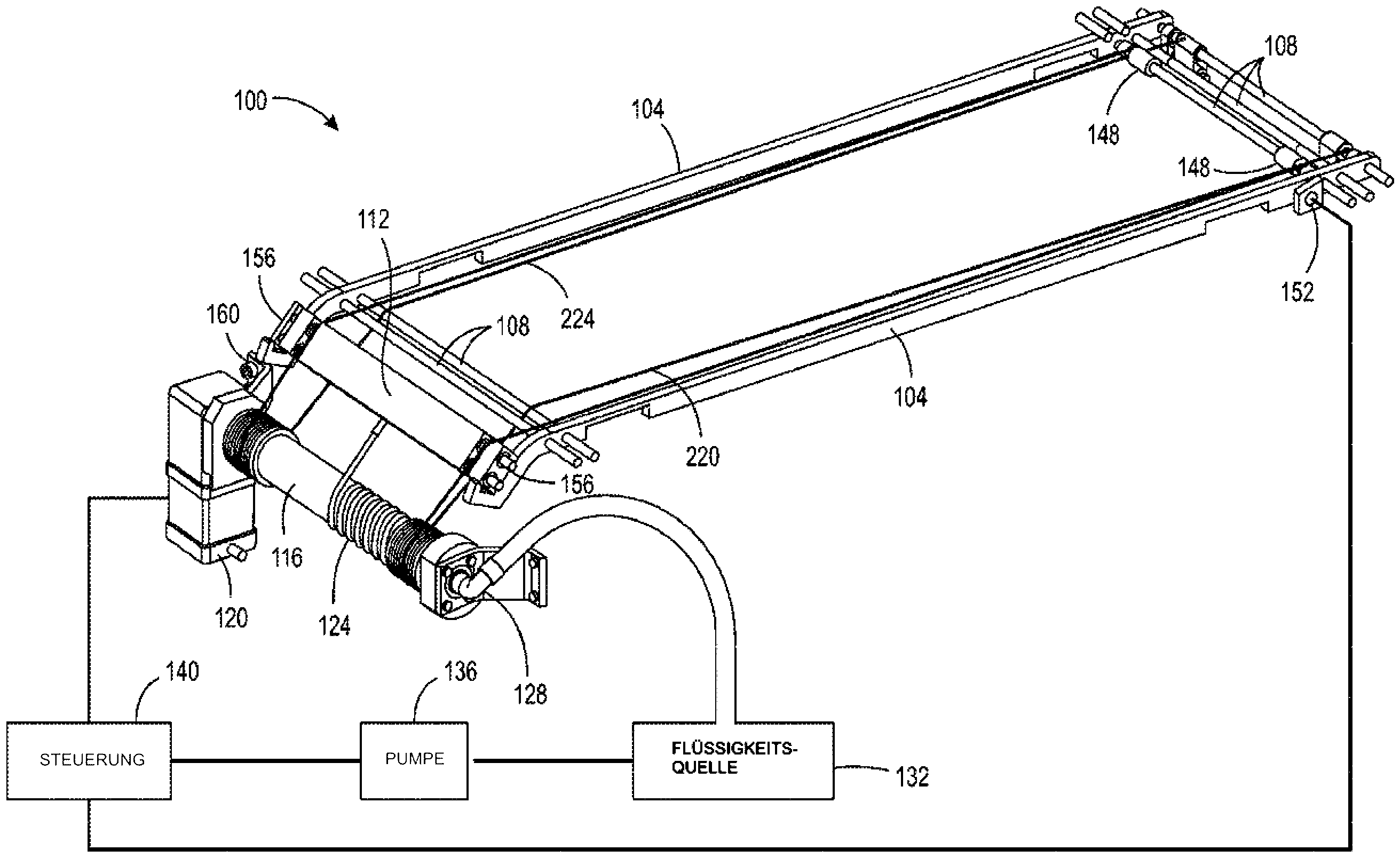
  • 1 ist eine Perspektivansicht eines Systems, das Komponenten, die zum Reinigen der Blende einer oder mehrerer Druckköpfe in einem Tintenstrahldrucker verwendet werden, reinigt.
  • 2 ist eine Querschnittsansicht eines rotierenden Schafts in dem System aus 1.
  • 3 ist eine Bodenansicht des in 2 gezeigten Schafts und Spülbauteils.
  • 4A ist eine Perspektivansicht eines Spannmechanismus in dem System aus 1.
  • 4B ist eine seitliche Perspektivansicht des Spannmechanismus, der in 4A gezeigt ist.
  • 4C ist eine Perspektivansicht des Spannmechanismus, der in 4A gezeigt ist, von unterhalb des Mechanismus.
  • 4D ist eine seitliche Perspektivansicht des Spannmechanismus, der in 4A gezeigt ist, von oberhalb des Mechanismus.
  • 5 ist eine Perspektivansicht eines Behälters, der positioniert ist, um Flüssigkeit von dem in 1 gezeigten System zu sammeln.
The above aspects and other features of a cleaning system that efficiently cleans components used to clean print heads in used with the printer are explained in the following description, in conjunction with the attached drawings.
  • 1 is a perspective view of a system that cleans components used to clean the aperture of one or more printheads in an inkjet printer.
  • 2 is a cross-sectional view of a rotating shaft in the system of 1 .
  • 3 is a ground view of the 2 shown shaft and flushing component.
  • 4A is a perspective view of a clamping mechanism in the system of 1 .
  • 4B is a side perspective view of the clamping mechanism used in 4A is shown.
  • 4C is a perspective view of the clamping mechanism used in 4A shown from below the mechanism.
  • 4D is a side perspective view of the clamping mechanism used in 4A shown from above the mechanism.
  • 5 is a perspective view of a container positioned to transfer liquid from the 1 system shown.

Für ein allgemeines Verständnis der vorliegenden Ausführungsformen wird auf die Zeichnungen Bezug genommen. In den Zeichnungen wurden durchgehend ähnliche Bezugszeichen verwendet, um ähnliche Elemente zu kennzeichnen.For a general understanding of the present embodiments, reference is made to the drawings. Throughout the drawings, similar reference numerals have been used to identify similar elements.

1 stellt ein System dar, das Komponenten reinigt, die verwendet werden, um die Blenden von Druckköpfen in einem Tintenstrahldrucker zu reinigen. Das System 100 enthält ein Paar Führungsschienen 104, eine Vielzahl von Querbauteilen 108, ein Spülbauteil 112, einen rotierenden Schaft 116, einen Aktuator 120, eine Flüssigkeitsquelle 132 und eine Pumpe 136. Die Führungsschienen 104 und die Querbauteile 108 bilden einen Rahmen, entlang dem sich das Spülbauteil 112 von der in 1 gezeigten Position zu dem anderen Ende des Rahmens und dann zurück zu der in 1 gezeigten Position bewegt. Das Spülbauteil 112 enthält ein oder mehr Räder 156 an jedem Ende des Spülbauteils 112, die den Rahmen entlang rollen, während die Schnüre 220 und 224 auf den Schaft 116 aufgewickelt und von ihm abgewickelt werden. Der Aktuator 120 hat einen rotierenden Ausgabeschaft, der mechanisch an Durchübertragungselement 204 (2) gekoppelt ist, das mit dem rotierenden Schaft 116 wirkverbunden ist, um den Schaft 116 um seine Längsachse zu drehen. Alternativ dazu kann der Ausgabeschaft des Aktuators 120 direkt mit dem Schaft 116 verbunden sein. Andere Arten von Aktuatoren können verwendet werden, um den Schaft 116 anzutreiben, wie ein Direktantrieb, ein Aktuator, der durch eine Übertragung angekoppelt ist, oder ein Aktuator, der eine Umlenkrolle und ein endloses Band oder eine Kette antreibt. Wie in 2 gezeigt ist, ist der Schaft 116 innerhalb von Lagern 212 montiert, um dem Aktuator 120 zu ermöglichen, den Schaft 116 zu rotieren. Der Schaft 116 enthält auch einen Verbindungsgang 208 (2), der an einem Ende mit einer rotierenden Kupplung 128 und am anderen Ende mit dem flexiblen Rohr 124 verbunden ist. Das flexible Rohr 124 ist um Schaft 116 gerollt und ein Ende des Rohrs 124 ist mit dem Spülbauteil 112 verbunden, um es Flüssigkeit zu ermöglichen, von der Flüssigkeitsquelle 132 zum Spülbauteil 112 zu fließen, wenn Steuerung 140 Pumpe 136 betreibt, um Flüssigkeit von der Flüssigkeitsquelle 132 zu pumpen. Die rotierende Kupplung 128 verbindet mit der Flüssigkeitsquelle 132, um es Flüssigkeit zu ermöglichen, von der Flüssigkeitsquelle 132 durch die Kupplung 128 hindurch und in den Verbindungsgang 208 zu fließen. Die Fähigkeit der Kupplung 128, zu rotieren wie der Schaft 116 rotiert, hilft, zu verhindern, dass der Schlauch, der die Kupplung zur Pumpe verbindet, abknickt. Außerdem hat, wie in 1 gezeigt ist, jede Schnur 220 und 224 erste und zweite Enden, die mit dem rotierenden Schaft 116 verbunden sind. Ein Abschnitt jeder Schnur verläuft auch durch einen Spannmechanismus 148 und die Querbauteile 108 hindurch, die von dem Schaft 116 weiter entfernt sind, als die Querbauteile 108, die dem Spülbauteil 112 an der ersten Position nahe sind. Ein Sensor 152 erzeugt ein Signal, das die Anwesenheit oder Abwesenheit des Spülbauteils 112 an dem entfernten Ende des Rahmens, der durch Führungsschienen 104 und die Querbauteile 108 gebildet ist, anzeigt. Ein ähnlicher Sensor 160 ist an dem Ende des Rahmens positioniert, das dem Aktuator 120 am nächsten ist, und er ist eingerichtet, ein Signal zu erzeugen, das die Anwesenheit oder Abwesenheit des Spülbauteils 112 an dem nahen Ende des Rahmens, der durch die Führungsschienen 104 und die Querbauteile 108 gebildet ist, anzeigt. Die Steuerung empfängt die Signale, die durch diese Sensoren erzeugt werden, und verwendet sie, um die Komponenten in dem Reinigungssystem 100 wie unten beschrieben zu betreiben. 1 illustrates a system that cleans components used to clean the apertures of printheads in an inkjet printer. The system 100 includes a pair of guide rails 104, a plurality of cross members 108, a purge member 112, a rotating shaft 116, an actuator 120, a fluid source 132, and a pump 136. The guide rails 104 and the cross members 108 form a frame along which the purge member 112 extends from the 1 shown position to the other end of the frame and then back to the position shown in 1 shown position. The flushing member 112 includes one or more wheels 156 at each end of the flushing member 112 that roll along the frame while the cords 220 and 224 are wound onto and unwound from the shaft 116. The actuator 120 has a rotating output shaft that is mechanically connected to the transmission member 204 ( 2 ) that is operatively connected to the rotating shaft 116 to rotate the shaft 116 about its longitudinal axis. Alternatively, the output shaft of the actuator 120 may be directly connected to the shaft 116. Other types of actuators may be used to drive the shaft 116, such as a direct drive, an actuator coupled through a transmission, or an actuator that drives a pulley and an endless belt or chain. As shown in 2 As shown, the shaft 116 is mounted within bearings 212 to allow the actuator 120 to rotate the shaft 116. The shaft 116 also includes a connecting passage 208 ( 2 ), which is connected at one end to a rotating coupling 128 and at the other end to the flexible tube 124. The flexible tube 124 is coiled around shaft 116, and one end of the tube 124 is connected to the flushing member 112 to allow fluid to flow from the fluid source 132 to the flushing member 112 when controller 140 operates pump 136 to pump fluid from the fluid source 132. The rotating coupling 128 connects to the fluid source 132 to allow fluid to flow from the fluid source 132 through the coupling 128 and into the connecting passage 208. The ability of the coupling 128 to rotate as the shaft 116 rotates helps prevent the hose connecting the coupling to the pump from kinking. Also, as shown in 1 As shown, each cord 220 and 224 has first and second ends connected to the rotating shaft 116. A portion of each cord also extends through a tensioning mechanism 148 and the cross members 108 that are farther from the shaft 116 than the cross members 108 that are proximate to the purge member 112 at the first position. A sensor 152 generates a signal indicative of the presence or absence of the purge member 112 at the far end of the frame formed by guide rails 104 and the cross members 108. A similar sensor 160 is positioned at the end of the frame closest to the actuator 120 and is configured to generate a signal indicative of the presence or absence of the purge member 112 at the proximal end of the frame formed by the guide rails 104 and the cross members 108. The controller receives the signals generated by these sensors and uses them to operate the components in the cleaning system 100 as described below.

Unter weiterer Bezugnahme auf 2 sind an jedem Ende des Schafts 116 geriffelte Muttern 216A und 216B montiert. Der mit Gewinde versehene Abschnitt der Muttern 216A und 216B hilft den Schnüren, sich ab- und aufzuwickeln, während der Schaft 116 rotiert, wie unten beschrieben. In der Figur ist das erste Ende 220a der Schnur 220 mit der geriffelten Mutter 216A verbunden und in einem Uhrzeigersinn um die Mutter gewickelt, während das zweite Ende 220b der Schnur 220 mit der geriffelten Mutter verbunden ist und entgegen einem Uhrzeigersinn um die Mutter gewickelt ist. In der Ausführungsform, die in 2 gezeigt ist, hat die geriffelte Mutter 216A, die dem Aktuator 120 am nächsten ist, ein linkshändiges Gewinde, während die Mutter 216B, die vom Aktuator weiter entfernt ist, ein rechtshändiges Gewinde hat. In ähnlicher Weise ist das erste Ende 224a einer Schnur 224 mit der geriffelten Mutter 216B verbunden und in einem Uhrzeigersinn um die Mutter gewickelt, während das zweite Ende 224b der Schnur 224 mit der geriffelten Mutter verbunden ist und entgegen einem Uhrzeigersinn um die Mutter gewickelt ist. Die Schnur 220 ist auch mit einem Ende des Spülbauteils 112 verbunden und die Schnur 224 ist mit dem gegenüberliegenden Ende des Spülbauteils 112 verbunden. Die Struktur zum Aufwickeln und Abwickeln der Schnüre an jedem Schaft 116 kann auch mit einem Paar Umlenkrollen, die an dem Schaft 116 an jedem Ende des Schafts befestigt sind, implementiert werden.With further reference to 2 Grooved nuts 216A and 216B are mounted on each end of the shaft 116. The threaded portion of the nuts 216A and 216B helps the cords unwind and wind as the shaft 116 rotates, as described below. In the figure, the first end 220a of the cord 220 is connected to the grooved nut 216A and wrapped around the nut in a clockwise direction, while the second end 220b of the cord 220 is connected to the grooved nut and wrapped around the nut in a counterclockwise direction. In the embodiment form, which in 2 As shown, the knurled nut 216A closest to the actuator 120 has a left-handed thread, while the nut 216B farther from the actuator has a right-handed thread. Similarly, the first end 224a of a cord 224 is connected to the knurled nut 216B and wrapped around the nut in a clockwise direction, while the second end 224b of the cord 224 is connected to the knurled nut and wrapped around the nut in a counterclockwise direction. The cord 220 is also connected to one end of the purge member 112, and the cord 224 is connected to the opposite end of the purge member 112. The structure for winding and unwinding the cords on each shaft 116 can also be implemented with a pair of pulleys attached to the shaft 116 at each end of the shaft.

Unter Bezugnahme auf 3 setzt sich die Länge der Schnur 220 zu dem Spannbauteil 148 an den entfernten Querbauteilen 108 fort, bevor sie zwischen den Querbauteilen 108 nahe dem Spülbauteil 112 an der ersten Position und dann zu dem zweite Ende 220b zurückkehrt. Gleichfalls setzt sich die Länge der Schnur 224 zu dem Spannbauteil 148 an den entfernten Querbauteilen 108 fort, bevor sie zwischen den Querbauteilen 108 nahe dem Spülbauteil 112 an der ersten Position und dann zu dem zweite Ende 224b zurückkehrt. Die Ansicht, die in 3 gezeigt ist, ist von unterhalb des Spülbauteils 112, um ein Feld von Öffnungen 228 in dem Spülbauteil 112 zu offenbaren. Die Öffnungen 228 gestatten der Flüssigkeit, von der Flüssigkeitsquelle 132 durch den Verbindungsgang 208 und Rohr 124 hindurch zu fließen, um das Spülbauteil 112 zu verlassen.With reference to 3 the length of the cord 220 continues to the tensioning member 148 at the remote cross members 108 before returning between the cross members 108 near the flushing member 112 at the first position and then to the second end 220b. Likewise, the length of the cord 224 continues to the tensioning member 148 at the remote cross members 108 before returning between the cross members 108 near the flushing member 112 at the first position and then to the second end 224b. The view shown in 3 is from below the purge member 112 to reveal an array of openings 228 in the purge member 112. The openings 228 allow fluid to flow from the fluid source 132 through the passageway 208 and tube 124 to exit the purge member 112.

4A, 4B, 4C und 4D stellen einen der Spannmechanismen 148 dar. Der Spannmechanismus 148 enthält zwei Unterbaugruppen 404A und 404B. Jede Unterbaugruppe enthält eine mechanische Verknüpfung 408, die jeweils zwei Umlenkrollen 412 haben, eine Torsionsfeder 416 (4C) und einen Schaft 420. Die mechanischen Verknüpfungen 408 sind um zwei der Querbauteile 108 herum montiert, sodass sich ein drittes Querbauteil zwischen den Verknüpfungen befindet. Die Verknüpfungen 408 sind an den Querbauteilen 108 durch Schnappringe 424 gesichert, die in Nuten in den Querbauteilen 108 passen, die in einem vorbestimmten Abstand von der Führungsschiene 104 lokalisiert sind. Die Verknüpfungen sind auch an den Schäften 420 durch Schnappringe 428 gesichert, die in Nuten an den Schäften zwischen den Verknüpfungen und der Führungsschiene 104 positioniert sind. Die Spannfedern 416 sind um die Querbauteile 108 herum innerhalb der Führungsschiene 104 montiert und ein Ende jeder Spannfeder 416 ist in eine Öffnung 432 in dem Schaft 420 eingesetzt. Das andere Ende jeder Spannfeder 416 ruht auf dem mittleren Querbauteil 108, wie in 4D gezeigt ist. Die Schnur 220 erstreckt sich von der geriffelten Mutter 216 zu einer der Umlenkrollen 412 in einer der Verknüpfungen 408. Von dort setzt sich die Schur um die andere Umlenkrolle der Verknüpfung fort und erstreckt sich dann hinter das mittlere Querbauteil 108 zu einer der Umlenkrollen in der anderen Verknüpfung 408. Die Schnur setzt sich dann zu der anderen Umlenkrolle 412 auf der anderen Verknüpfung 408 fort und folgt entlang der Schnur 220 zu der Spülstange 112 und dann zurück zur geriffelten Mutter 2016 (1) 4A , 4B , 4C and 4D represent one of the tensioning mechanisms 148. The tensioning mechanism 148 includes two subassemblies 404A and 404B. Each subassembly includes a mechanical linkage 408, each having two pulleys 412, a torsion spring 416 ( 4C ) and a shaft 420. The mechanical linkages 408 are mounted around two of the cross members 108 such that a third cross member is located between the linkages. The linkages 408 are secured to the cross members 108 by snap rings 424 that fit into grooves in the cross members 108 located at a predetermined distance from the guide rail 104. The linkages are also secured to the shafts 420 by snap rings 428 that are positioned in grooves on the shafts between the linkages and the guide rail 104. The tension springs 416 are mounted around the cross members 108 within the guide rail 104, and one end of each tension spring 416 is inserted into an opening 432 in the shaft 420. The other end of each tension spring 416 rests on the central cross member 108, as shown in 4D is shown. The cord 220 extends from the knurled nut 216 to one of the pulleys 412 in one of the links 408. From there, the cord continues around the other pulley of the link and then extends behind the central cross member 108 to one of the pulleys in the other link 408. The cord then continues to the other pulley 412 on the other link 408 and follows along the cord 220 to the flush rod 112 and then back to the knurled nut 2016 ( 1 )

Jede mechanische Verknüpfung arbeitet um zwei Achsen herum, von denen eine fest ist und durch das Querbauteil, um das die Verknüpfung herum montiert ist, definiert ist, und die andere rotiert um das Querbauteil und ist durch den Schaft 420 definiert. Die Umlenkrollen 412 führen die Schnur 220 und stellen eine verringerte Reibung sicher, wenn sich die Schnur bewegt, weil der Schaft 116 rotiert. Die Schnur 220 wird um die Umlenkrollen 412 verlegt, um Spannstabilität sicherzustellen, während die Länge des Pfads der Schnur variiert, wenn die Spülstange 112 ihre Position nahe des Aktuators 120 verlässt und sich entlang der Führungsschienen 104 bewegt. Während sich die Schnurpfadlänge verringert, bewegen Torsionsfedern 416 den rotierenden Schaft 420 abwärts, um die Schnurpfadlängenvariation auszugleichen und Spannung in der Schnur aufrechtzuerhalten. Während sich die Schnurpfadlänge vergrößert, werden die Torsionsfedern 416 komprimiert und der rotierende Schaft 420 bewegt sich aufwärts, um die Schnurpfadlängenvariation auszugleichen und die Spannungserhöhung in der Schnur zu begrenzen. Die Spannmechanismen 148 ermöglichen es der Nennspannung der Schnüre 220 und 224 auch, angepasst zu werden.Each mechanical linkage operates around two axes, one of which is fixed and defined by the cross member around which the linkage is mounted, and the other of which rotates around the cross member and is defined by the shaft 420. The pulleys 412 guide the cord 220 and ensure reduced friction as the cord moves because the shaft 116 rotates. The cord 220 is routed around the pulleys 412 to ensure tension stability while the cord path length varies as the flush rod 112 leaves its position near the actuator 120 and moves along the guide rails 104. As the cord path length decreases, torsion springs 416 move the rotating shaft 420 downward to compensate for the cord path length variation and maintain tension in the cord. As the line path length increases, the torsion springs 416 compress and the rotating shaft 420 moves upward to compensate for the line path length variation and limit the increase in tension in the line. The tensioning mechanisms 148 also allow the nominal tension of the lines 220 and 224 to be adjusted.

5 stellt einen Behälter 504 dar, an dem das Reinigungssystem 100 montiert ist. Der Behälter 504 ist integral aus einem thermoplastische Material hergestellt, um ein Volumen unterhalb das Reinigungssystems 100 und der Komponenten des Druckkopfreinigungssystems bereitzustellen, obwohl der Behälter auch aus Metall, einem Polymermaterial oder geformtem Plastik hergestellt sein könnte. Wenn das Reinigungssystem verwendet wird, ist das Druckkopfreinigungssystem zwischen den Schnüren 220 und 224 und dem Behälter 504 positioniert, sodass die Spülstange 112 Reinigungsflüssigkeit auf die Komponenten des Druckkopfreinigungssystems auswerfen kann. Das Reinigungssystem 100 ist in Bezug auf den Behälter 504 so angeordnet, dass die Schnüre 220 und 224 durch den Schlitz 516 hindurch verlaufen, so dass sich die Spülstange 112 mit den rotierenden Schnüren bewegen kann, während sie Reinigungsflüssigkeit auf die Komponenten des Druckkopfreinigungssystems auswirft. Der rotierende Schaft 116 und der Aktuator 120 des Reinigungssystems 100 sind außerhalb des Volumens innerhalb des Behälters 504 positioniert. Während das Reinigungssystem betrieben wird, um die Druckkopfreinigungssystemkomponenten mit Reinigungsflüssigkeit von der Flüssigkeitsquelle 132 durchzuspülen, fällt die Flüssigkeit von den Komponenten des Druckkopfreinigungssystems in den Behälter 504. Behälter 504 enthält eine Öffnung 508 im Boden des Behälters 504, die der verwendeten Reinigungsflüssigkeit ermöglicht, aus dem Behälter herauszufließen. Die verwendete Reinigungsflüssigkeit kann passiv durch Schwerkraft oder durch eine andere Pumpe, die mit der Öffnung 508 wirkverbunden ist, entfernt werden. Nahe an der Öffnung 508 ist ein Flüssigkeitsniveausensor 512 positioniert. Der Flüssigkeitsniveausensor 512 ist dafür eingerichtet, ein Signal zu erzeugen, das ein Versagen der Öffnung in dem Behälter 504, die Reinigungsflüssigkeit von dem Behältervolumen abzulassen, anzeigt. Die Steuerung 140 ist mit dem Sensor 512 verbunden, um dieses Signal zu empfangen, und die Steuerung ist dafür eingerichtet, in Antwort auf das Signal, das das Ablassversagen anzeigt, ein Signal zu erzeugen, das anzeigt, dass die Öffnung 508 verstopft ist. 5 depicts a reservoir 504 to which the cleaning system 100 is mounted. The reservoir 504 is integrally formed from a thermoplastic material to provide volume beneath the cleaning system 100 and the components of the printhead cleaning system, although the reservoir could also be formed from metal, a polymer material, or molded plastic. When the cleaning system is in use, the printhead cleaning system is positioned between the cords 220 and 224 and the reservoir 504 so that the purge rod 112 can eject cleaning fluid onto the components of the printhead cleaning system. The cleaning system 100 is arranged with respect to the reservoir 504 such that the cords 220 and 224 pass through the slot 516 so that the purge rod 112 can move with the rotating cords while ejecting cleaning fluid onto the components of the printhead cleaning system. The rotating shaft 116 and the actuator 120 of the cleaning system 100 are positioned outside the volume within reservoir 504. As the cleaning system operates to flush the printhead cleaning system components with cleaning fluid from fluid source 132, the fluid from the printhead cleaning system components falls into reservoir 504. Reservoir 504 includes an opening 508 in the bottom of reservoir 504 that allows the used cleaning fluid to flow out of the reservoir. The used cleaning fluid can be passively removed by gravity or by another pump operatively connected to opening 508. A fluid level sensor 512 is positioned near opening 508. Fluid level sensor 512 is configured to generate a signal indicating a failure of the opening in reservoir 504 to drain the cleaning fluid from the reservoir volume. The controller 140 is connected to the sensor 512 to receive this signal, and the controller is configured to generate a signal indicating that the orifice 508 is clogged in response to the signal indicating the vent failure.

Im Betrieb wird das Druckkopfreinigungssystem von Zeit zu Zeit bewegt, sodass die Spülstange 112 des Reinigungssystems 100 über das Druckkopfreinigungssystem hinweg laufen kann. Sobald es platziert ist, betreibt die Steuerung 140 den Aktuator 120, um in die Richtung entgegen dem Uhrzeigersinn zu rotieren, um den Abschnitt der Schnüre 220 und 224, die um die geriffelten Muttern 216 an den Enden des Schafts 116 im Uhrzeigersinn gerollt sind, abzuwickeln. Während dieses Abwickeln der Schnüre stattfindet, empfangen die anderen Enden der Schnüre 220 und 224 einen Abschnitt der Schnüre und rollen sie um den anderen Abschnitt der geriffelten Muttern auf den Enden des Schafts an dem zweiten Ende der Schnüre herum. Die Spannmechanismen 148 halten die Schnüre stramm, während dieses Abwickeln und Aufwickeln der Schnüre stattfinden und die Räder 156 des Spülbauteils 112 rollen entlang dem Paar Führungsschienen 104. Die Steuerung 140 betreibt auch die Pumpe 136, um Reinigungsflüssigkeit von der Flüssigkeitsquelle 132 in den Verbindungsgang 208 des Schafts 116 und Rohr 124 zu bewegen, damit sie in das Spülbauteil 112 gelangt. Der Druck der fließenden Reinigungsflüssigkeit ermöglicht den Öffnungen 228 in dem Spülbauteil, die Reinigungsflüssigkeit auf die Komponenten des Druckkopfreinigungssystems freizusetzen und der Behälter beginnt, die Flüssigkeit zu empfangen, während sie von den Komponenten tropft. Wenn die Steuerung 140 ein Signal von dem Sensor 152 empfängt, dass das Spülbauteil 112 das entfernte Ende des Rahmens erreicht hat, betreibt die Steuerung 140 den Aktuator 120, die Richtung der Rotation seines Ausgabeschafts umzukehren. Diese Rotation im Uhrzeigersinn wickelt den Abschnitt der Schnüre 220 und 224, die entgegen dem Uhrzeigersinn um die geriffelten Muttern 216 an den Enden des Schafts 116 gerollt sind, ab. Während diese Abwicklung der Schnüre stattfindet, empfangen die anderen Enden der Schnüre 220 und 224 einen Abschnitt der Schnüre und rollen sie um die geriffelten Muttern 216 an den Enden des Schafts 166 an den ersten Enden der Schnüre. Die Spannmechanismen 148 halten die Schnüre stramm, während dieses Abwickeln und Aufwickeln der Schnüre stattfindet, und die Räder 156 des Spülbauteils 112 rollen entlang einem Paar Führungsschienen 104, um das Spülglied 112 zur ersten Position zurückzubewegen. Wenn die Steuerung 140 feststellt, dass das Signal von dem Sensor 160 anzeigt, dass das Spülbauteil 112 seine erste Position erreicht hat, deaktiviert es den Aktuator 120 und die Pumpe 136. Das Druckkopfreinigungssystem kann an eine Position zurückbewegt werden, wo es verwendet werden kann, um die Blenden von Druckköpfen zu reinigen.In operation, the printhead cleaning system is moved from time to time so that the purge rod 112 of the cleaning system 100 can pass over the printhead cleaning system. Once in place, the controller 140 operates the actuator 120 to rotate in a counterclockwise direction to unwind the portion of the cords 220 and 224 that are rolled clockwise around the knurled nuts 216 on the ends of the shaft 116. While this unwinding of the cords is taking place, the other ends of the cords 220 and 224 receive one portion of the cords and roll them around the other portion of the knurled nuts on the ends of the shaft at the second end of the cords. The tensioning mechanisms 148 hold the cords taut during this unwinding and rewinding of the cords, and the wheels 156 of the purge assembly 112 roll along the pair of guide rails 104. The controller 140 also operates the pump 136 to move cleaning fluid from the fluid source 132 into the connecting passage 208 of the shaft 116 and tube 124 to enter the purge assembly 112. The pressure of the flowing cleaning fluid allows the orifices 228 in the purge assembly to release the cleaning fluid onto the components of the printhead cleaning system, and the reservoir begins to receive the fluid as it drips from the components. When the controller 140 receives a signal from the sensor 152 that the purge assembly 112 has reached the far end of the frame, the controller 140 operates the actuator 120 to reverse the direction of rotation of its dispensing shaft. This clockwise rotation unwinds the portion of cords 220 and 224 that are rolled counterclockwise around the knurled nuts 216 at the ends of the shaft 116. While this unwinding of the cords is taking place, the other ends of the cords 220 and 224 receive a portion of the cords and roll them around the knurled nuts 216 at the ends of the shaft 166 at the first ends of the cords. The tensioning mechanisms 148 hold the cords taut while this unwinding and winding of the cords takes place, and the wheels 156 of the purge member 112 roll along a pair of guide rails 104 to return the purge member 112 to the first position. When the controller 140 determines that the signal from the sensor 160 indicates that the purge member 112 has reached its first position, it deactivates the actuator 120 and the pump 136. The printhead cleaning system can be moved back to a position where it can be used to clean the apertures of printheads.

Claims (10)

System (100) zum Reinigen von Komponenten in einem Druckkopfreinigungssystem, das zum Reinigen eines Druckkopfs in einem Tintenstrahldrucker benutzt wird, umfassend: ein Paar paralleler Bauteile (104); mindestens zwei Querbauteile (108), die das Paar paralleler Bauteile (104) schneiden, um einen Rahmen zu bilden; einen Aktuator (120), der mit einem bidirektional rotierenden Ausgabeschaft eingerichtet ist; einen Schaft (116), der mit dem rotierenden Ausgabeschaft des Aktuators (120) wirkverbunden ist, um mit dem Ausgabeschaft zu rotieren, wenn der Aktuator (120) den Ausgabeschaft rotiert; ein Bauteil (112), das eine Vielzahl von Öffnungen (228) hat, wobei das Bauteil (112) pneumatisch mit einer Flüssigkeitsquelle (132) verbunden ist, um einer Flüssigkeit zu ermöglichen, von der Flüssigkeitsquelle (132) zu dem Bauteil (112) zu fließen und durch die Öffnungen (228) hindurch auf Komponenten des Druckkopfreinigungssystems in dem Tintenstrahldrucker auszutreten, wobei das Bauteil (112) parallel zu den mindestens zwei Querbauteilen (108) ist; und eine erste Schnur (220), die ein erstes Ende (220A) und ein zweites Ende (220B) hat, wobei das erste Ende (220A) direkt mit einer ersten geriffelten Mutter (216A) verbunden ist, die um den Schaft (116) montiert ist, und in einer ersten Wickelrichtung um den Schaft (116) gewickelt ist und wobei das zweite Ende (220B) direkt mit der ersten geriffelten Mutter (116A) verbunden ist, die um den Schaft (116) montiert ist, und in einer zweiten Wickelrichtung, der ersten Wickelrichtung entgegengesetzten Wickelrichtung um den Schaft (116) gewickelt ist, und die erste Schnur (220) mit dem Bauteil (112) wirkverbunden ist, um den Schaft (116) zu rotieren und das Bauteil (112) von einer ersten Position an einem Ende des Paars paralleler Bauteile (104) zu einer zweiten Position am anderen Ende des Paars paralleler Bauteile (104) an den Komponenten des Druckkopfreinigungssystems in dem Tintenstrahldrucker vorbeigehend zu bewegen, während die Flüssigkeit durch die Öffnungen (228) in dem Bauteil (112) hindurch austritt und auf die Komponenten des Druckkopfreinigungssystems fällt, und das Bauteil (112) zu der ersten Position zurückzubewegen.A system (100) for cleaning components in a printhead cleaning system used to clean a printhead in an inkjet printer, comprising: a pair of parallel members (104); at least two transverse members (108) intersecting the pair of parallel members (104) to form a frame; an actuator (120) configured with a bidirectionally rotating output shaft; a shaft (116) operatively connected to the rotating output shaft of the actuator (120) for rotating with the output shaft when the actuator (120) rotates the output shaft; a member (112) having a plurality of openings (228), the member (112) being pneumatically connected to a fluid source (132) to allow a fluid to flow from the fluid source (132) to the member (112) and exit through the openings (228) onto components of the printhead cleaning system in the inkjet printer, the member (112) being parallel to the at least two transverse members (108); and a first cord (220) having a first end (220A) and a second end (220B), wherein the first end (220A) is directly connected to a first knurled nut (216A) mounted around the shaft (116) and wound around the shaft (116) in a first winding direction, and wherein the second end (220B) is directly connected to the first knurled nut (116A) mounted around the shaft (116) and wound around the shaft (116) in a second winding direction opposite the first winding direction, and the first cord (220) is operatively connected to the component (112) to rotate the shaft (116) and to move the member (112) from a first position at one end of the pair of parallel members (104) to a second position at the other end of the pair of parallel members (104) past the components of the printhead cleaning system in the inkjet printer while the liquid exits through the openings (228) in the member (112) and falls onto the components of the printhead cleaning system, and to move the member (112) back to the first position. System (100) nach Anspruch 1, wobei eines der mindestens zwei Querbauteile (108) sich in einem größeren Abstand von dem Schaft (116) befindet als das andere Querbauteile der mindestens zwei Querbauteile (108) und ein Abschnitt der ersten Schnur (220) um das Querbauteil herum verläuft, das mit einem größeren Abstand von dem Schaft angeordnet ist als das andere Querbauteil.System (100) according to Claim 1 wherein one of the at least two transverse components (108) is located at a greater distance from the shaft (116) than the other transverse component of the at least two transverse components (108) and a portion of the first cord (220) extends around the transverse component which is arranged at a greater distance from the shaft than the other transverse component. System (100) nach Anspruch 2, wobei der Schaft ferner umfasst: einen Verbindungsgang (208) innerhalb des Schafts (116), wobei der Verbindungsgang (208) ein erstes Ende und ein zweites Ende hat; eine rotierende Kupplung (128) an dem Schaft (116), die dafür eingerichtet ist, das erste Ende des Verbindungsgangs (208) pneumatisch mit der Flüssigkeitsquelle (132) zu verbinden; und ein flexibles Hohlbauteil (124), das ein erstes Ende und ein zweites Ende hat, wobei das erste Ende des flexiblen Hohlbauteils (124) pneumatisch mit dem zweiten Ende des Verbindungsgangs (208) verbunden ist und das zweite Ende des flexiblen Hohlbauteils (124) mit dem Bauteil (112) verbunden ist, wobei das flexible Hohlbauteil (124) um den Schaft (116) herum gewickelt ist, um dem flexiblen Hohlbauteil (124) zu ermöglichen, sich von dem Schaft (116) abzuwickeln und dem Bauteil (112) zu folgen, während sich das Bauteil (112) von der ersten Position zu der zweiten Position über den Komponenten des Druckkopfreinigungssystem bewegt, und um das flexible Hohlbauteil (124) um den Schaft (116) zu wickeln, während das Bauteil (112) zu der ersten Position aus der zweiten Position zurückkehrt.System (100) according to Claim 2 , wherein the shaft further comprises: a connecting passage (208) within the shaft (116), the connecting passage (208) having a first end and a second end; a rotating coupling (128) on the shaft (116) configured to pneumatically connect the first end of the connecting passage (208) to the fluid source (132); and a flexible hollow member (124) having a first end and a second end, the first end of the flexible hollow member (124) being pneumatically connected to the second end of the connecting passageway (208) and the second end of the flexible hollow member (124) being connected to the member (112), the flexible hollow member (124) being wrapped around the shaft (116) to allow the flexible hollow member (124) to unwind from the shaft (116) and follow the member (112) as the member (112) moves from the first position to the second position over the components of the printhead cleaning system, and to wrap the flexible hollow member (124) around the shaft (116) as the member (112) returns to the first position from the second position. System (100) nach Anspruch 1, das Bauteil (112) ferner umfassend: mindestens zwei Räder (156), wobei ein Rad mit dem Bauteil (112) an einem Ende des Bauteils verbunden ist, um dem einen Rad zu ermöglichen, entlang eines der parallelen Bauteile zu rollen, und das andere Rad mit dem Bauteil an einem gegenüberliegenden Ende des Bauteils verbunden ist, um dem anderen Rad zu ermöglichen, entlang des anderen parallelen Bauteils zu rollen.System (100) according to Claim 1 , the component (112) further comprising: at least two wheels (156), wherein one wheel is connected to the component (112) at one end of the component to allow the one wheel to roll along one of the parallel components, and the other wheel is connected to the component at an opposite end of the component to allow the other wheel to roll along the other parallel component. System (100) nach Anspruch 4, ferner umfassend: eine zweite Schnur (224), wobei die zweite Schnur ein erstes Ende (224A) und ein zweites Ende (224B) hat, wobei das erste Ende (224A) der zweiten Schnur (224) direkt mit einer zweiten geriffelten Mutter (216B) verbunden ist, die an einem zweiten Ende (224B) um den Schaft (116) montiert ist und in der zweiten Wickelrichtung an dem zweiten Ende (224B) um den Schaft (116) gewickelt ist und wobei das zweite Ende (224B) der zweiten Schnur (224) direkt mit der zweiten geriffelten Mutter (216B) verbunden ist, die an dem zweiten Ende (224B) um den Schaft (116) montiert ist, und in der ersten Wickelrichtung an dem zweiten Ende (224B) um den Schaft (116) gewickelt ist, wobei jede der ersten und zweiten Schnur (220, 224) mit dem Bauteil (112) wirkverbunden ist, um den Schaft (116) in eine erste Richtung zu rotieren, um das Bauteil (112) von einer ersten Position an einem Ende des Paars paralleler Bauteile (104) zu einer zweiten Position an einem anderen Ende des Paars paralleler Bauteile (104) an den Komponenten des Druckkopfreinigungssystems in dem Tintenstrahldrucker vorbeigehend zu bewegen, während die Flüssigkeit durch die Öffnungen (228) in dem Bauteil (112) austritt und auf die Komponenten des Druckkopfreinigungssystems fällt, und um den Schaft in eine Richtung, die der ersten Richtung entgegengesetzt ist, zu rotieren, um das Bauteil (112) in die erste Position zurückzubewegen.System (100) according to Claim 4 , further comprising: a second cord (224), the second cord having a first end (224A) and a second end (224B), the first end (224A) of the second cord (224) being directly connected to a second knurled nut (216B) mounted at a second end (224B) around the shaft (116) and wound around the shaft (116) in the second winding direction at the second end (224B), and the second end (224B) of the second cord (224) being directly connected to the second knurled nut (216B) mounted at the second end (224B) around the shaft (116) and wound around the shaft (116) in the first winding direction at the second end (224B), each of the first and second cords (220, 224) being operatively connected to the component (112) is to rotate the shaft (116) in a first direction to move the member (112) from a first position at one end of the pair of parallel members (104) to a second position at another end of the pair of parallel members (104) past the components of the printhead cleaning system in the inkjet printer while the liquid exits through the openings (228) in the member (112) and falls onto the components of the printhead cleaning system, and to rotate the shaft in a direction opposite the first direction to move the member (112) back to the first position. System (100) nach Anspruch 5, ferner umfassend: mindestens zwei Spannmechanismen (148), wobei ein Spannmechanismus an einem Ende des Querbauteils (108) positioniert ist, das weiter vom Schaft (116) positioniert ist als das andere Querbauteil (108) der mindestens zwei Querbauteile (108), und wobei der andere Spannmechanismus an einem gegenüberliegenden Ende des Querbauteils positioniert ist, das weiter vom Schaft positioniert ist als das andere Querbauteil der mindestens zwei Querbauteile; und die erste Schnur (220) durch einen der mindestens zwei Spannmechanismen (148) hindurch gewickelt ist und die zweite Schnur (224) durch den anderen der mindestens zwei Spannmechanismen (148) hindurch gewickelt ist.System (100) according to Claim 5 , further comprising: at least two tensioning mechanisms (148), wherein one tensioning mechanism is positioned at an end of the cross member (108) that is positioned farther from the shaft (116) than the other cross member (108) of the at least two cross members (108), and wherein the other tensioning mechanism is positioned at an opposite end of the cross member that is positioned farther from the shaft than the other cross member of the at least two cross members; and the first cord (220) is wound through one of the at least two tensioning mechanisms (148) and the second cord (224) is wound through the other of the at least two tensioning mechanisms (148). System (100) nach Anspruch 6, wobei jeder Spannmechanismus (148) ferner umfasst: mindestens eine Spannfeder (416); und eine Vielzahl von Umlenkrollen (412), die an dem Querbauteil (108) montiert sind, das in dem Abstand positioniert ist, der weiter als der Abstand ist, in dem das andere Querbauteil der mindestens zwei Querbauteile (108) von dem Schaft (116) entfernt ist, wobei die mindestens eine Spannfeder (416) die Umlenkrollen (412) von einander weg drängt, um die erste Schnur (220) oder die zweite Schnur (224), die durch den Spannmechanismus (148) hindurch gewickelt ist, stramm zu halten.System (100) according to Claim 6 , wherein each tensioning mechanism (148) further comprises: at least one tension spring (416); and a plurality of pulleys (412) mounted on the cross member (108) positioned at the distance greater than the distance the other cross member of the at least two cross members (108) is from the shaft (116), wherein the at least one tension spring (416) urges the pulleys (412) away from each other to keep the first cord (220) or the second cord (224) wound through the tensioning mechanism (148) taut. System (100) nach Anspruch 1, ferner umfassend: einen Behälter (504), der dafür positioniert ist, die Flüssigkeit, die von den Öffnungen (228) in dem Bauteil (112) emittiert wird, zu empfangen, nachdem die Flüssigkeit von den Komponenten des Druckkopfreinigungssystems gefallen ist, der zwischen dem Behälter (504) und dem Paar paralleler Bauteile (104) positioniert ist.System (100) according to Claim 1 , further comprising: a reservoir (504) positioned to receive the liquid emitted from the openings (228) in the member (112) after the liquid has fallen from the components of the printhead cleaning system, positioned between the reservoir (504) and the pair of parallel members (104). System (100) nach Anspruch 8, der Behälter (504) ferner umfassend: eine Öffnung (508) in einem Boden des Behälters (504), um zu ermöglichen, Flüssigkeit, die in dem Behälter (504) gesammelt ist, zu entfernen, nachdem das Fluid von den Komponenten des Druckkopfreinigungssystems gefallen ist.System (100) according to Claim 8 , the container (504) further comprising: an opening (508) in a bottom of the container (504) to enable liquid collected in the container (504) to be removed after the fluid has fallen from the components of the printhead cleaning system. System (100) nach Anspruch 9, ferner umfassend: einen Flüssigkeitsniveausensor (512), der in der Nähe der Öffnung in dem Boden des Behälters positioniert ist, wobei der Flüssigkeitsniveausensor dafür eingerichtet ist, ein Signal zu erzeugen, das ein Versagen des Behälters anzeigt, die gesammelte Flüssigkeit durch die Öffnung in dem Boden des Behälters hindurch abzulassen.System (100) according to Claim 9 , further comprising: a liquid level sensor (512) positioned proximate the opening in the bottom of the container, the liquid level sensor being configured to generate a signal indicative of a failure of the container to drain the collected liquid through the opening in the bottom of the container.
DE102017213295.7A 2016-08-02 2017-08-01 IMPROVED SYSTEM FOR CLEANING COMPONENTS USED TO CLEAN INKJET PRINTHEADS IN INKJET PRINTERS Active DE102017213295B4 (en)

Applications Claiming Priority (4)

Application Number Priority Date Filing Date Title
US201662369892P 2016-08-02 2016-08-02
US62/369,892 2016-08-02
US15/228,431 US10046566B2 (en) 2016-08-02 2016-08-04 System for cleaning components used to clean inkjet printheads in inkjet printers
US15/228,431 2016-08-04

Publications (2)

Publication Number Publication Date
DE102017213295A1 DE102017213295A1 (en) 2018-02-08
DE102017213295B4 true DE102017213295B4 (en) 2025-05-28

Family

ID=60996375

Family Applications (1)

Application Number Title Priority Date Filing Date
DE102017213295.7A Active DE102017213295B4 (en) 2016-08-02 2017-08-01 IMPROVED SYSTEM FOR CLEANING COMPONENTS USED TO CLEAN INKJET PRINTHEADS IN INKJET PRINTERS

Country Status (1)

Country Link
DE (1) DE102017213295B4 (en)

Citations (5)

* Cited by examiner, † Cited by third party
Publication number Priority date Publication date Assignee Title
US6810889B2 (en) * 2001-04-16 2004-11-02 Hercules Systems, Inc. Vehicle washing apparatus
DE60319337T2 (en) * 2003-03-06 2009-03-05 Hewlett-Packard Development Co., L.P., Houston Printer maintenance system and procedure
US20090179950A1 (en) * 2008-01-16 2009-07-16 Silverbrook Research Pty Ltd Printhead maintenance facility with nozzle face wiper having single skew blade
US8777214B2 (en) * 2011-09-15 2014-07-15 Konica Minolta, Inc. Sheet feeder and image forming apparatus
US20180037031A1 (en) * 2016-08-02 2018-02-08 Xerox Corporation System for cleaning components used to clean inkjet printheads in inkjet printers

Patent Citations (5)

* Cited by examiner, † Cited by third party
Publication number Priority date Publication date Assignee Title
US6810889B2 (en) * 2001-04-16 2004-11-02 Hercules Systems, Inc. Vehicle washing apparatus
DE60319337T2 (en) * 2003-03-06 2009-03-05 Hewlett-Packard Development Co., L.P., Houston Printer maintenance system and procedure
US20090179950A1 (en) * 2008-01-16 2009-07-16 Silverbrook Research Pty Ltd Printhead maintenance facility with nozzle face wiper having single skew blade
US8777214B2 (en) * 2011-09-15 2014-07-15 Konica Minolta, Inc. Sheet feeder and image forming apparatus
US20180037031A1 (en) * 2016-08-02 2018-02-08 Xerox Corporation System for cleaning components used to clean inkjet printheads in inkjet printers

Also Published As

Publication number Publication date
DE102017213295A1 (en) 2018-02-08

Similar Documents

Publication Publication Date Title
DE60301603T2 (en) Maintenance procedure for an inkjet printhead
DE10028318B4 (en) Method and apparatus for cleaning a printhead of an inkjet printer
DE69319065T2 (en) Cleaning device with wiper blade for a color jet print head
DE60300063T2 (en) Ink jet recording apparatus
DE19749670B4 (en) A system for wet cleaning a printhead wherein a printhead treatment fluid is applied without direct contact
DE3128366C2 (en)
DE69320439T2 (en) Trolley for the cover device of an inkjet printer maintenance station
DE60102860T2 (en) Solvent dispenser for conveyor belt cleaner and application process
DE3030795C2 (en)
DE10147999B4 (en) Inkjet cover with vent
DE69508454T2 (en) Improved cleaning device and an ink jet recording device provided therewith
DE10152591A1 (en) Pressure compensation device for ink cartridges of inkjet printers
DE60122093T2 (en) A waiting station for printers with ejection nozzles perpendicular to the carriage movement direction
DE102017213295B4 (en) IMPROVED SYSTEM FOR CLEANING COMPONENTS USED TO CLEAN INKJET PRINTHEADS IN INKJET PRINTERS
US10668730B2 (en) System for cleaning components used to clean inkjet printheads in inkjet printers
DE2613149A1 (en) DEVICE FOR CLEANING CONVEYOR BELTS
DE602006000911T2 (en) Imaging device
WO1999004975A2 (en) Method and device for covering and cleaning the nozzles of an ink-jet print head
DE602005000725T2 (en) Ink jet recording apparatus
DE602005000446T2 (en) Ink jet recording apparatus and its maintenance mechanism
DE60014488T2 (en) Screen printing device with a cleaning unit that can be replaced within a stencil
DE3142700C2 (en) Paper guide for printer
DE3712923A1 (en) THERMAL INK PRINTER
DE102012106416A1 (en) Printer for printing image on recording medium, has collecting container comprising tank for humidification liquid, which is passed from tank into space between pressure latch and collecting container
DE2756334B2 (en) Device for covering the nozzle surface on an ink writing head in an ink writing mechanism

Legal Events

Date Code Title Description
R082 Change of representative

Representative=s name: GRUENECKER PATENT- UND RECHTSANWAELTE PARTG MB, DE

R012 Request for examination validly filed
R016 Response to examination communication
R018 Grant decision by examination section/examining division