DE102017120624A1 - Textile reinforcement arrangement, method for its production and separating and / or shaping device for use in this method - Google Patents
Textile reinforcement arrangement, method for its production and separating and / or shaping device for use in this method Download PDFInfo
- Publication number
- DE102017120624A1 DE102017120624A1 DE102017120624.8A DE102017120624A DE102017120624A1 DE 102017120624 A1 DE102017120624 A1 DE 102017120624A1 DE 102017120624 A DE102017120624 A DE 102017120624A DE 102017120624 A1 DE102017120624 A1 DE 102017120624A1
- Authority
- DE
- Germany
- Prior art keywords
- pin
- grid body
- reinforcing
- grid
- textile reinforcement
- Prior art date
- Legal status (The legal status is an assumption and is not a legal conclusion. Google has not performed a legal analysis and makes no representation as to the accuracy of the status listed.)
- Withdrawn
Links
- 230000002787 reinforcement Effects 0.000 title claims abstract description 92
- 239000004753 textile Substances 0.000 title claims abstract description 73
- 238000007493 shaping process Methods 0.000 title claims description 29
- 238000004519 manufacturing process Methods 0.000 title claims description 12
- 238000000034 method Methods 0.000 title claims description 11
- 230000003014 reinforcing effect Effects 0.000 claims abstract description 69
- 239000004033 plastic Substances 0.000 claims abstract description 67
- 229920003023 plastic Polymers 0.000 claims abstract description 67
- 239000011159 matrix material Substances 0.000 claims abstract description 44
- 238000004873 anchoring Methods 0.000 claims abstract description 36
- 239000000835 fiber Substances 0.000 claims abstract description 26
- 239000004566 building material Substances 0.000 claims description 48
- 238000009415 formwork Methods 0.000 claims description 28
- 230000015572 biosynthetic process Effects 0.000 claims description 3
- 238000009416 shuttering Methods 0.000 claims description 3
- 239000002131 composite material Substances 0.000 abstract description 11
- 230000009467 reduction Effects 0.000 abstract description 2
- 238000004132 cross linking Methods 0.000 description 13
- 238000000926 separation method Methods 0.000 description 13
- 239000004567 concrete Substances 0.000 description 12
- 229920000642 polymer Polymers 0.000 description 9
- 230000009466 transformation Effects 0.000 description 8
- 239000000463 material Substances 0.000 description 7
- 125000006850 spacer group Chemical group 0.000 description 6
- 229910052799 carbon Inorganic materials 0.000 description 5
- 238000005520 cutting process Methods 0.000 description 5
- 230000032798 delamination Effects 0.000 description 5
- 230000008569 process Effects 0.000 description 5
- 239000012783 reinforcing fiber Substances 0.000 description 5
- 230000002441 reversible effect Effects 0.000 description 5
- 238000005698 Diels-Alder reaction Methods 0.000 description 4
- 238000005336 cracking Methods 0.000 description 4
- 239000000126 substance Substances 0.000 description 4
- 229920001169 thermoplastic Polymers 0.000 description 4
- 239000004416 thermosoftening plastic Substances 0.000 description 4
- 238000006742 Retro-Diels-Alder reaction Methods 0.000 description 3
- 150000001412 amines Chemical class 0.000 description 3
- 238000010276 construction Methods 0.000 description 3
- 229920001577 copolymer Polymers 0.000 description 3
- 125000002897 diene group Chemical group 0.000 description 3
- 239000012948 isocyanate Substances 0.000 description 3
- 150000002513 isocyanates Chemical class 0.000 description 3
- WBYWAXJHAXSJNI-UHFFFAOYSA-N methyl p-hydroxycinnamate Natural products OC(=O)C=CC1=CC=CC=C1 WBYWAXJHAXSJNI-UHFFFAOYSA-N 0.000 description 3
- 230000004048 modification Effects 0.000 description 3
- 238000012986 modification Methods 0.000 description 3
- 230000005855 radiation Effects 0.000 description 3
- 229920003048 styrene butadiene rubber Polymers 0.000 description 3
- WBYWAXJHAXSJNI-VOTSOKGWSA-M .beta-Phenylacrylic acid Natural products [O-]C(=O)\C=C\C1=CC=CC=C1 WBYWAXJHAXSJNI-VOTSOKGWSA-M 0.000 description 2
- WBYWAXJHAXSJNI-SREVYHEPSA-N Cinnamic acid Chemical compound OC(=O)\C=C/C1=CC=CC=C1 WBYWAXJHAXSJNI-SREVYHEPSA-N 0.000 description 2
- 239000012988 Dithioester Substances 0.000 description 2
- 229920002943 EPDM rubber Polymers 0.000 description 2
- 229920000181 Ethylene propylene rubber Polymers 0.000 description 2
- 229920002430 Fibre-reinforced plastic Polymers 0.000 description 2
- 239000005058 Isophorone diisocyanate Substances 0.000 description 2
- 238000005452 bending Methods 0.000 description 2
- 239000007767 bonding agent Substances 0.000 description 2
- CQEYYJKEWSMYFG-UHFFFAOYSA-N butyl acrylate Chemical compound CCCCOC(=O)C=C CQEYYJKEWSMYFG-UHFFFAOYSA-N 0.000 description 2
- 229930016911 cinnamic acid Natural products 0.000 description 2
- 235000013985 cinnamic acid Nutrition 0.000 description 2
- 238000004049 embossing Methods 0.000 description 2
- 239000011151 fibre-reinforced plastic Substances 0.000 description 2
- 239000003365 glass fiber Substances 0.000 description 2
- 230000009477 glass transition Effects 0.000 description 2
- NIMLQBUJDJZYEJ-UHFFFAOYSA-N isophorone diisocyanate Chemical compound CC1(C)CC(N=C=O)CC(C)(CN=C=O)C1 NIMLQBUJDJZYEJ-UHFFFAOYSA-N 0.000 description 2
- 238000006116 polymerization reaction Methods 0.000 description 2
- -1 polysiloxane Polymers 0.000 description 2
- 230000003716 rejuvenation Effects 0.000 description 2
- 238000004904 shortening Methods 0.000 description 2
- 229920001187 thermosetting polymer Polymers 0.000 description 2
- MEIRRNXMZYDVDW-MQQKCMAXSA-N (2E,4E)-2,4-hexadien-1-ol Chemical compound C\C=C\C=C\CO MEIRRNXMZYDVDW-MQQKCMAXSA-N 0.000 description 1
- FEIQOMCWGDNMHM-KBXRYBNXSA-N (2e,4e)-5-phenylpenta-2,4-dienoic acid Chemical compound OC(=O)\C=C\C=C\C1=CC=CC=C1 FEIQOMCWGDNMHM-KBXRYBNXSA-N 0.000 description 1
- BUHVIAUBTBOHAG-FOYDDCNASA-N (2r,3r,4s,5r)-2-[6-[[2-(3,5-dimethoxyphenyl)-2-(2-methylphenyl)ethyl]amino]purin-9-yl]-5-(hydroxymethyl)oxolane-3,4-diol Chemical compound COC1=CC(OC)=CC(C(CNC=2C=3N=CN(C=3N=CN=2)[C@H]2[C@@H]([C@H](O)[C@@H](CO)O2)O)C=2C(=CC=CC=2)C)=C1 BUHVIAUBTBOHAG-FOYDDCNASA-N 0.000 description 1
- ATOUXIOKEJWULN-UHFFFAOYSA-N 1,6-diisocyanato-2,2,4-trimethylhexane Chemical compound O=C=NCCC(C)CC(C)(C)CN=C=O ATOUXIOKEJWULN-UHFFFAOYSA-N 0.000 description 1
- WJIOHMVWGVGWJW-UHFFFAOYSA-N 3-methyl-n-[4-[(3-methylpyrazole-1-carbonyl)amino]butyl]pyrazole-1-carboxamide Chemical compound N1=C(C)C=CN1C(=O)NCCCCNC(=O)N1N=C(C)C=C1 WJIOHMVWGVGWJW-UHFFFAOYSA-N 0.000 description 1
- 229920002748 Basalt fiber Polymers 0.000 description 1
- 101100165186 Caenorhabditis elegans bath-34 gene Proteins 0.000 description 1
- 229920000049 Carbon (fiber) Polymers 0.000 description 1
- PMPVIKIVABFJJI-UHFFFAOYSA-N Cyclobutane Chemical compound C1CCC1 PMPVIKIVABFJJI-UHFFFAOYSA-N 0.000 description 1
- 239000004593 Epoxy Substances 0.000 description 1
- LFQSCWFLJHTTHZ-UHFFFAOYSA-N Ethanol Chemical compound CCO LFQSCWFLJHTTHZ-UHFFFAOYSA-N 0.000 description 1
- VGGSQFUCUMXWEO-UHFFFAOYSA-N Ethene Chemical compound C=C VGGSQFUCUMXWEO-UHFFFAOYSA-N 0.000 description 1
- 239000005977 Ethylene Substances 0.000 description 1
- WOBHKFSMXKNTIM-UHFFFAOYSA-N Hydroxyethyl methacrylate Chemical compound CC(=C)C(=O)OCCO WOBHKFSMXKNTIM-UHFFFAOYSA-N 0.000 description 1
- VVQNEPGJFQJSBK-UHFFFAOYSA-N Methyl methacrylate Chemical compound COC(=O)C(C)=C VVQNEPGJFQJSBK-UHFFFAOYSA-N 0.000 description 1
- 239000004952 Polyamide Substances 0.000 description 1
- 239000005062 Polybutadiene Substances 0.000 description 1
- 239000002202 Polyethylene glycol Substances 0.000 description 1
- 239000004721 Polyphenylene oxide Substances 0.000 description 1
- 239000004793 Polystyrene Substances 0.000 description 1
- 229910001294 Reinforcing steel Inorganic materials 0.000 description 1
- XTXRWKRVRITETP-UHFFFAOYSA-N Vinyl acetate Chemical compound CC(=O)OC=C XTXRWKRVRITETP-UHFFFAOYSA-N 0.000 description 1
- 239000002253 acid Substances 0.000 description 1
- 239000004676 acrylonitrile butadiene styrene Substances 0.000 description 1
- 239000002318 adhesion promoter Substances 0.000 description 1
- 230000009286 beneficial effect Effects 0.000 description 1
- 238000009435 building construction Methods 0.000 description 1
- 239000004917 carbon fiber Substances 0.000 description 1
- 239000004568 cement Substances 0.000 description 1
- FEIQOMCWGDNMHM-UHFFFAOYSA-N cinnamylideneacetic acid Natural products OC(=O)C=CC=CC1=CC=CC=C1 FEIQOMCWGDNMHM-UHFFFAOYSA-N 0.000 description 1
- 150000001875 compounds Chemical class 0.000 description 1
- 238000001816 cooling Methods 0.000 description 1
- 150000001893 coumarin derivatives Chemical class 0.000 description 1
- 229920006037 cross link polymer Polymers 0.000 description 1
- 125000001995 cyclobutyl group Chemical group [H]C1([H])C([H])([H])C([H])(*)C1([H])[H] 0.000 description 1
- 230000007423 decrease Effects 0.000 description 1
- 230000003247 decreasing effect Effects 0.000 description 1
- 230000001419 dependent effect Effects 0.000 description 1
- 150000004985 diamines Chemical class 0.000 description 1
- 150000001993 dienes Chemical class 0.000 description 1
- 125000005442 diisocyanate group Chemical group 0.000 description 1
- 238000006073 displacement reaction Methods 0.000 description 1
- 125000005022 dithioester group Chemical group 0.000 description 1
- 230000005670 electromagnetic radiation Effects 0.000 description 1
- 239000003822 epoxy resin Substances 0.000 description 1
- BEFDCLMNVWHSGT-UHFFFAOYSA-N ethenylcyclopentane Chemical compound C=CC1CCCC1 BEFDCLMNVWHSGT-UHFFFAOYSA-N 0.000 description 1
- 239000004744 fabric Substances 0.000 description 1
- 125000000524 functional group Chemical group 0.000 description 1
- 229910052500 inorganic mineral Inorganic materials 0.000 description 1
- 238000009434 installation Methods 0.000 description 1
- 230000001788 irregular Effects 0.000 description 1
- ZFSLODLOARCGLH-UHFFFAOYSA-N isocyanuric acid Chemical compound OC1=NC(O)=NC(O)=N1 ZFSLODLOARCGLH-UHFFFAOYSA-N 0.000 description 1
- 239000007788 liquid Substances 0.000 description 1
- 239000011707 mineral Substances 0.000 description 1
- 239000004570 mortar (masonry) Substances 0.000 description 1
- 238000000465 moulding Methods 0.000 description 1
- 229920000058 polyacrylate Polymers 0.000 description 1
- 229920002239 polyacrylonitrile Polymers 0.000 description 1
- 229920013639 polyalphaolefin Polymers 0.000 description 1
- 229920002647 polyamide Polymers 0.000 description 1
- 229920000768 polyamine Polymers 0.000 description 1
- 229920002857 polybutadiene Polymers 0.000 description 1
- 239000004417 polycarbonate Substances 0.000 description 1
- 229920000515 polycarbonate Polymers 0.000 description 1
- 229920000647 polyepoxide Polymers 0.000 description 1
- 229920000728 polyester Polymers 0.000 description 1
- 229920001225 polyester resin Polymers 0.000 description 1
- 239000004645 polyester resin Substances 0.000 description 1
- 229920006149 polyester-amide block copolymer Polymers 0.000 description 1
- 229920000570 polyether Polymers 0.000 description 1
- 229920001223 polyethylene glycol Polymers 0.000 description 1
- 229920000193 polymethacrylate Polymers 0.000 description 1
- 229920001296 polysiloxane Polymers 0.000 description 1
- 229920002223 polystyrene Polymers 0.000 description 1
- 239000004814 polyurethane Substances 0.000 description 1
- 229920002635 polyurethane Polymers 0.000 description 1
- 238000002360 preparation method Methods 0.000 description 1
- 238000003825 pressing Methods 0.000 description 1
- 229920005989 resin Polymers 0.000 description 1
- 239000011347 resin Substances 0.000 description 1
- 229940075582 sorbic acid Drugs 0.000 description 1
- 235000010199 sorbic acid Nutrition 0.000 description 1
- 239000004334 sorbic acid Substances 0.000 description 1
- 150000001629 stilbenes Chemical class 0.000 description 1
- 235000021286 stilbenes Nutrition 0.000 description 1
- 150000005846 sugar alcohols Polymers 0.000 description 1
- 229920002994 synthetic fiber Polymers 0.000 description 1
- 239000012209 synthetic fiber Substances 0.000 description 1
- 229920005992 thermoplastic resin Polymers 0.000 description 1
- 230000007704 transition Effects 0.000 description 1
- 238000002604 ultrasonography Methods 0.000 description 1
- XLYOFNOQVPJJNP-UHFFFAOYSA-N water Substances O XLYOFNOQVPJJNP-UHFFFAOYSA-N 0.000 description 1
Images


Classifications
-
- B—PERFORMING OPERATIONS; TRANSPORTING
- B29—WORKING OF PLASTICS; WORKING OF SUBSTANCES IN A PLASTIC STATE IN GENERAL
- B29C—SHAPING OR JOINING OF PLASTICS; SHAPING OF MATERIAL IN A PLASTIC STATE, NOT OTHERWISE PROVIDED FOR; AFTER-TREATMENT OF THE SHAPED PRODUCTS, e.g. REPAIRING
- B29C70/00—Shaping composites, i.e. plastics material comprising reinforcements, fillers or preformed parts, e.g. inserts
- B29C70/68—Shaping composites, i.e. plastics material comprising reinforcements, fillers or preformed parts, e.g. inserts by incorporating or moulding on preformed parts, e.g. inserts or layers, e.g. foam blocks
- B29C70/688—Shaping composites, i.e. plastics material comprising reinforcements, fillers or preformed parts, e.g. inserts by incorporating or moulding on preformed parts, e.g. inserts or layers, e.g. foam blocks the inserts being meshes or lattices
-
- E—FIXED CONSTRUCTIONS
- E04—BUILDING
- E04C—STRUCTURAL ELEMENTS; BUILDING MATERIALS
- E04C5/00—Reinforcing elements, e.g. for concrete; Auxiliary elements therefor
- E04C5/07—Reinforcing elements of material other than metal, e.g. of glass, of plastics, or not exclusively made of metal
-
- E—FIXED CONSTRUCTIONS
- E04—BUILDING
- E04C—STRUCTURAL ELEMENTS; BUILDING MATERIALS
- E04C5/00—Reinforcing elements, e.g. for concrete; Auxiliary elements therefor
- E04C5/16—Auxiliary parts for reinforcements, e.g. connectors, spacers, stirrups
- E04C5/20—Auxiliary parts for reinforcements, e.g. connectors, spacers, stirrups of material other than metal or with only additional metal parts, e.g. concrete or plastics spacers with metal binding wires
-
- B—PERFORMING OPERATIONS; TRANSPORTING
- B29—WORKING OF PLASTICS; WORKING OF SUBSTANCES IN A PLASTIC STATE IN GENERAL
- B29K—INDEXING SCHEME ASSOCIATED WITH SUBCLASSES B29B, B29C OR B29D, RELATING TO MOULDING MATERIALS OR TO MATERIALS FOR MOULDS, REINFORCEMENTS, FILLERS OR PREFORMED PARTS, e.g. INSERTS
- B29K2105/00—Condition, form or state of moulded material or of the material to be shaped
- B29K2105/06—Condition, form or state of moulded material or of the material to be shaped containing reinforcements, fillers or inserts
- B29K2105/20—Inserts
- B29K2105/206—Meshes, lattices or nets
Landscapes
- Engineering & Computer Science (AREA)
- Architecture (AREA)
- Civil Engineering (AREA)
- Structural Engineering (AREA)
- Chemical & Material Sciences (AREA)
- Composite Materials (AREA)
- Mechanical Engineering (AREA)
- Reinforcement Elements For Buildings (AREA)
Abstract
Die Erfindung betrifft eine Textilbewehrungsanordnung (20) mit einem Gitterkörper (22) und mehreren Bewehrungsstiften (40), die am Gitterkörper (22) mittelbar oder unmittelbar angeordnet sind. Jeder Bewehrungsstift (40) hat zwei Stiftabschnitte (41), die auf unterschiedlichen Seiten des Gitterkörpers (22) angeordnet sind. Die Bewehrungsstifte (40) erstrecken sich im Wesentlichen rechtwinklig durch den Gitterkörper hindurch. Jeder Stiftabschnitt (41) hat einen Verankerungsteil (43). Der Verankerungsteil (43) kann durch eine Erweiterung und/oder Verringerung der Querschnittsfläche des betreffenden Stiftabschnitts (41) gebildet sein. Sowohl der Gitterkörper, als auch die Bewehrungsstifte sind aus einem Verbundwerkstoff mit einem in eine Kunststoffmatrix (K) eingebetteten Textilfaserstrang (29) ausgebildet.

Description
Die vorliegende Erfindung betrifft eine Textilbewehrungsanordnung, ein Verfahren zu dessen Herstellung sowie eine Trenn- und/oder Formgebungseinrichtung, die bei dem Verfahren zur Herstellung der Textilbewehrungsanordnung verwendet werden kann.The present invention relates to a textile reinforcement assembly, a method of making the same and a separating and / or shaping device that can be used in the method of manufacturing the textile reinforcement assembly.
Im Kunststoffbau werden heute Verstärkungsfasern eingesetzt, um die mechanischen Eigenschaften des Kunststoffes zu erhöhen, beispielsweise beim Bau von Flugzeugen, Booten oder dergleichen. Dabei müssen die Verstärkungsfasern dem Verbundwerkstoffteil zum einen eine ausreichende Zugfestigkeit geben und andererseits das Formen des Verbundwerkstoffes ermöglichen.
Bewehrungen aus faserverstärkten Kunststoffen für die Verstärkung von Bauproduktbauteilen oder Baustoffbauteilen (z.B. Betonbauteilen) unterliegen anderen Anforderungen als ein Verbundmaterial für ein Kunststoffbauteil. Sie müssen resistent sein gegen die im mineralischen Baustoff (z.B. Beton) verwendeten Medien, insbesondere gegenüber alkalischen Substanzen. Außerdem muss eine Temperaturbeständigkeit von bis zu 80°C dauerhaft gegeben sein. Schließlich sollen sich solche Bewehrungen einfach und kostengünstig herstellen lassen und vor Ort auf der Baustelle oder im Fertigteilwerk einfach zu handhaben sein.Reinforcements of fiber reinforced plastics for reinforcement of building product components or building material components (e.g., concrete components) are subject to different requirements than a composite material for a plastic component. They must be resistant to the media used in the mineral building material (e.g., concrete), especially alkaline substances. In addition, a temperature resistance of up to 80 ° C must be permanent. Finally, such reinforcements should be easy and inexpensive to produce and be easy to handle on site or in the precast plant.
Ein weiteres Bewehrungselement ist in
Ein Verfahren zur Herstellung eines faserverstärkten Verstärkungselements ist in
Bewehrte Baustoff- bzw. Betonbauteile weisen üblicherweise mehrere Risse quer zur Bewehrungsrichtung auf. Derartige Querrisse sind gewünscht, um die Bewehrung in der Baustoffmatrix (Beton) zu aktivieren. Wenn die Bewehrung in der Baustoffmatrix jedoch zu hohe Querzugspannungen aufbaut, beispielsweise durch eine ungünstige Rippengeometrie an den Bewehrungselementen oder zu geringe Betonüberdeckungen, kann es zu einer Rissbildung längs zur Bewehrungsrichtung kommen (Längs- oder Spaltrissbildung). Werden gitterartige Bewehrungsstrukturen mit geringen Gitterabständen verwendet, bilden sich die Längsrisse in Form einer Delamination in der Bewehrungs- bzw. Gitterebene aus. Bei konventioneller Betonstahlbewehrung wird dieser Sachverhalt durch konstruktive Bewehrungsregeln und eine optimierte Rippengeometrie stark begrenzt. Bei neuartigen Bewehrungsgittern aus faserverstärkten Kunststoffen hat sich in jüngster Zeit eine erheblich stärkere Neigung zur beschriebenen Längsrissbildung in Form von Delamination gezeigt. Zurückzuführen ist dies auf den Fertigungsprozess des Bewehrungsgitters und den damit einhergehenden Unregelmäßigkeiten der Bewehrungsquerschnitte sowie auf die Eigenschaften des verwendeten Kunststoffmaterials, mit dem die Verstärkungsfasern getränkt werden.Reinforced Baustoff- or concrete components usually have multiple cracks transverse to the direction of reinforcement. Such transverse cracks are desired to activate the reinforcement in the building material matrix (concrete). However, if the reinforcement in the building material matrix builds up too high transverse tensile stresses, for example as a result of unfavorable rib geometry on the reinforcement elements or insufficient concrete coverages, cracks can form along the direction of reinforcement (longitudinal or cracking cracks). If lattice-like reinforcement structures with small lattice spacings are used, the longitudinal cracks form in the form of a delamination in the reinforcement or lattice plane. With conventional reinforcing steel reinforcement this situation is strongly limited by constructive reinforcement rules and an optimized rib geometry. In the case of novel reinforcing gratings made of fiber-reinforced plastics, there has recently been shown a considerably greater tendency for the described longitudinal cracking in the form of delamination. This is due to the production process of the reinforcing grid and the associated irregularities of the reinforcement cross-sections and to the properties of the plastic material used, with which the reinforcing fibers are impregnated.
Es kann als Aufgabe der vorliegenden Erfindung angesehen werden, einen Textilbewehrungskörper zu schaffen, der sich einfach herstellen und in ein Baustoffbauteil - insbesondere ein Betonbauteil - integrieren lässt und die Gefahr der Delamination mindert.It can be regarded as an object of the present invention to provide a textile reinforcement body which is easy to produce and can be integrated into a building material component - in particular a concrete component - and reduces the risk of delamination.
Diese Aufgabe wird durch einen Textilbewehrungskörper mit den Merkmalen des Patentanspruches 1, ein Verfahren zu dessen Herstellung mit den Merkmalen des Patentanspruches 13 sowie eine Trenn- und/oder Formgebungseinrichtung zur Verwendung bei dem Herstellungsverfahren nach Patentanspruch 15 gelöst.This object is achieved by a textile reinforcing body with the features of claim 1, a method for its preparation with the features of
Erfindungsgemäß weist die Textilbewehrungsanordnung einen Gitterkörper mit sich in einer ersten Richtung erstreckenden ersten Gitterstababschnitten und sich in einer zweiten Richtung erstreckenden zweiten Gitterstababschnitten auf. An Kreuzungsstellen sind die Gitterstababschnitte miteinander verbunden. Die erste Richtung und die zweite Richtung können rechtwinklig oder schräg zueinander ausgerichtet sein und spannen eine Ebene auf, die nachfolgend als Gitterebene bezeichnet wird.According to the invention, the textile reinforcement arrangement has a grid body with first grid bar sections extending in a first direction and second grid bar sections extending in a second direction. At intersections, the grid bar sections are interconnected. The first direction and the second direction may be oriented at right angles or obliquely to one another and form a plane, which is referred to below as a lattice plane.
Die Textilbewehrungsanordnung weist außerdem Bewehrungsstifte auf, die sich quer zur Gitterebene erstrecken. Jeder Bewehrungsstift hat zwei Stiftabschnitte. Die Stiftabschnitte sind auf entgegengesetzten Seiten des Gitterkörpers angeordnet. Jeder Stiftabschnitt hat wenigstens einen Verankerungsteil. Der Verankerungsteil kann durch eine Erweiterung und/oder eine Vertiefung rechtwinklig zur Erstreckungsrichtung des jeweiligen Stiftabschnitts gebildet sein. Quer zu seiner Erstreckungsrichtung hat der Stiftabschnitt durch den wenigstens einen Verankerungsteil eine sich zumindest abschnittsweise erweiternde und/oder verjüngende Gestalt, um sich in einer Baustoffmatrix eines Baustoffkörpers über einen Formschluss fest verankern zu können. The fabric reinforcement assembly also has reinforcing pins that extend across the lattice plane. Each reinforcement pin has two pin sections. The pin portions are disposed on opposite sides of the grid body. Each pin portion has at least one anchoring part. The anchoring part may be formed by an extension and / or a recess at right angles to the extension direction of the respective pin portion. Transverse to its direction of extension of the pin portion has at least one anchoring part at least partially widening and / or tapered shape in order to anchor firmly in a building material matrix of a building material body via a positive connection can.
Die erste Richtung bzw. die zweite Richtung, entlang der sich die Gitterstababschnitte erstrecken, kann geradlinig ausgerichtet sein. Es ist alternativ auch möglich, dass der Gitterkörper an einer oder mehreren Stellen gebogen oder abgewinkelt ist. In diesem Fall ändert sich die erste Richtung bzw. die zweite Richtung an der Stelle der Biegung bzw. des Knicks oder Winkels des Gitterkörpers. Im Hinblick auf die Ausrichtung der Bewehrungsstifte wird jeweils die Stelle betrachtet, an der ein Bewehrungsstift den Gitterkörper durchsetzt. Verlaufen die Gitterstababschnitte an dieser Stelle geradlinig, spannen sie die Gitterebene bezogen auf diese Stelle des betrachteten Bewehrungsstiftes auf. Ist die Stelle, an der ein Bewehrungsstift den Gitterkörper durchsetzt, gekrümmt, so ist die Gitterebene durch eine Tangentialebene an den gekrümmten Verlauf des Gitterkörpers gebildet.The first direction or the second direction, along which the grating bar sections extend, can be rectilinearly aligned. Alternatively, it is also possible that the grid body is bent or angled at one or more points. In this case, the first direction or the second direction changes at the location of the bend or the bend or angle of the grid body. With regard to the orientation of the reinforcing pins, the point at which a reinforcing pin penetrates the grid body is considered in each case. If the lattice bar sections run straight at this point, they span the lattice plane with reference to this point of the reinforcement pin considered. If the point at which a reinforcing pin passes through the grid body is curved, then the grid plane is formed by a tangential plane to the curved course of the grid body.
Die Bewehrungsstifte und die Gitterstababschnitte des Gitterkörpers weisen jeweils einen in eine Kunststoffmatrix eingebetteten Textilfaserstrang auf. Der Textilfaserstrang dient dazu, Zugkräfte aufzunehmen.The reinforcing pins and the grid bar sections of the grid body each have a textile fiber strand embedded in a plastic matrix. The textile fiber strand serves to absorb tensile forces.
Ein den die Textilbewehrungsanordnung aufweisender Baustoffkörper kann Zugkräfte in die Erstreckungsrichtung der Gitterstababschnitte des Gitterkörpers aufnehmen, das heißt insbesondere in die erste Richtung und in die zweite Richtung. Häufig wird bei textilbewehrten Baustoffkörpern die Überdeckung des Gitterkörpers gering gewählt. Abhängig von den aufzunehmenden Zugkräften kann die Maschengröße des Gitterkörpers, also der Abstand zwischen den ersten Gitterstababschnitten in der zweiten Richtung und der Abstand der zweiten Gitterstababschnitte in der ersten Richtung relativ klein sein. Dies kann dazu führen, dass der Gitterkörper in der Gitterebene quasi eine Trennschicht zwischen den angrenzenden Baustoffschichten bildet. Bei auftretender Zugbelastung der Bewehrung kann es durch die damit einhergehenden Relativverschiebungen zwischen Bewehrung und Beton zur Spaltrissbildung im Bereich der Gitterebene kommen. Diese Neigung zur Spaltrissbildung bzw. der Delamination wird durch die Bewehrungsstifte erheblich vermindert, die die Gitterebene durchsetzen und jeweils einen Stiftabschnitt auf den beiden Seiten des Gitterkörpers aufweisen. Die Bewehrungsstifte enthalten ebenfalls einen Textilfaserstrang, der in eine Kunststoffmatrix eingebettet und möglichst zugsteif ausgebildet ist und können daher auch Zugkräfte in eine dritte Richtung aufnehmen, die rechtwinklig oder schräg zur Gitterebene verläuft. Die dritte Richtung hat vorzugsweise einen Winkel von größer als 70 Grad oder größer als 80 Grad relativ zur Gitterebene. Vorzugsweise ist die dritte Richtung rechtwinklig zur Gitterebene und mithin rechtwinklig zur ersten Richtung und zur zweiten Richtung orientiert.A building material body having the textile reinforcement arrangement can absorb tensile forces in the direction of extension of the grid bar sections of the grid body, that is to say in particular in the first direction and in the second direction. Frequently, the coverage of the grid body is selected low in textile-reinforced building materials. Depending on the tensile forces to be absorbed, the mesh size of the grid body, that is to say the distance between the first grid bar sections in the second direction and the spacing of the second grid bar sections in the first direction, can be relatively small. This can lead to the grid body in the lattice plane forming a kind of separating layer between the adjacent building material layers. When occurring tensile load of the reinforcement, it may come through the associated relative displacement between the reinforcement and concrete cracking in the area of the lattice plane. This tendency to fissure cracking or delamination is significantly reduced by the reinforcing pins which pass through the lattice plane and each having a pin portion on the two sides of the grid body. The reinforcing pins also contain a textile fiber strand, which is embedded in a plastic matrix and formed as possible zugsteif and therefore can also absorb tensile forces in a third direction, which is perpendicular or oblique to the lattice plane. The third direction preferably has an angle of greater than 70 degrees or greater than 80 degrees relative to the lattice plane. Preferably, the third direction is oriented at right angles to the lattice plane and thus at right angles to the first direction and to the second direction.
Durch die zusätzlichen Bewehrungsstifte wird ein Zusammenhalt der Baustoffmatrix des Baustoffkörpers auf beiden Seiten des Gitterkörpers erreicht. Dabei ist es wesentlich, dass die Bewehrungsstifte durch den wenigstens einen Verankerungsteil in der Baustoffmatrix fixiert werden können. Durch eine solche Ausgestaltung lässt sich das Delaminieren wirksam reduzieren bzw. verhindern, auch bei Baustoffbauteilen, die nur eine geringe Überdeckung des Gitterkörpers von wenigen Zentimetern aufweisen.Due to the additional reinforcement pins a cohesion of the building material matrix of the building material body is achieved on both sides of the grid body. It is essential that the reinforcing pins can be fixed by the at least one anchoring part in the building material matrix. By such a configuration, the delamination can effectively reduce or prevent, even with building material components that have only a small coverage of the grid body of a few centimeters.
Der Gitterkörper kann dadurch hergestellt sein, dass die Textilfaserstränge in die erste Richtung und die zweite Richtung aufeinandergelegt und gemeinsam in eine Kunststoffmatrix eingebettet werden. Die ersten Gitterstababschnitte und die zweiten Gitterstababschnitte werden somit durch das bzw. beim Herstellen des Gitterkörpers integral miteinander verbunden. Alternativ oder zusätzlich dazu ist es auch möglich, Stäbe herzustellen, beispielsweise durch ein Pultrusionsverfahren, und diese Stäbe anschließend zu verbinden.The grid body can be made by stacking the textile fiber strands in the first direction and the second direction and embedding them together in a plastic matrix. The first grid bar sections and the second grid bar sections are thus integrally connected with each other by the grid body. Alternatively or additionally, it is also possible to produce rods, for example by a pultrusion process, and then to join these rods.
Die Kunststoffmatrix des wenigstens einen Bewehrungsstiftes kann identisch sein mit der Kunststoffmatrix der Gitterstababschnitte des Gitterkörpers.The plastic matrix of the at least one reinforcing pin can be identical to the plastic matrix of the grid bar sections of the grid body.
Als Kunststoffmatrix für die Gitterstababschnitte bzw. den Gitterkörper und die Bewehrungsstifte kann bei einem Ausführungsbeispiel Epoxidharz oder Styrol-Butadien-Kautschuk (SBR) verwendet werden. Alternativ dazu ist es auch möglich, einen Thermoplasten ein reversibel quervernetztes Kunststoffmaterial für die Kunststoffmatrix zu verwenden. Beispielsweise kann es sich um einen Kunststoff handeln, der mittels einer Diels-Alder-Reaktion vernetzbar und mittels einer Retro-Diels-Alder-Reaktion auftrennbar ist.As a plastic matrix for the grid bar sections or the grid body and the reinforcing pins, epoxy resin or styrene-butadiene rubber (SBR) can be used in one embodiment. Alternatively, it is also possible to use a thermoplastic a reversibly cross-linked plastic material for the plastic matrix. For example, it can be a plastic which can be crosslinked by means of a Diels-Alder reaction and can be separated by means of a retro-Diels-Alder reaction.
Jeder Bewehrungsstift ist vorzugsweise im Bereich zwischen den beiden Stiftabschnitten mittelbar oder unmittelbar am Gitterkörper befestigt. Die Befestigung muss nicht dazu eingerichtet sein, große Kräfte aufzunehmen. Sie dient nur der Ausrichtung und Positionierung der Bewehrungsstifte. Die Befestigung kann beispielsweise durch eine Haftvermittlung erreicht werden. Zusätzlich oder alternativ können auch mechanische Befestigungsmittel, wie etwa Klemmen oder Umwicklungen oder dergleichen verwendet werden, um die Bewehrungsstifte am Gitterkörper anzuordnen. Bei einer Verbindung durch eine Haftvermittlung kann als Haftvermittler ein Kunststoff verwendet werden, wie er auch für die Kunststoffmatrix des Gitterkörpers bzw. der Bewehrungsstifte verwendet wird. Handelt es sich bei der Kunststoffmatrix um ein reversibel quervernetztes Kunststoffmaterial, können die Quervernetzungen aufgetrennt, die Bewehrungsstäbe mit dem Gitterkörper in Kontakt gebracht und die Quervernetzungen wieder hergestellt werden.Each reinforcing pin is preferably attached directly or indirectly to the grid body in the region between the two pin sections. The attachment does not have to be large To absorb forces. It only serves to align and position the reinforcement pins. The attachment can be achieved for example by a bonding agent. Additionally or alternatively, mechanical fasteners such as clamps or wraps or the like may also be used to locate the rebars on the grid body. In a compound by an adhesion promoter can be used as a bonding agent, a plastic, as it is also used for the plastic matrix of the grid body or the reinforcing pins. If the plastic matrix is a reversibly cross-linked plastic material, the cross-links can be separated, the reinforcing bars brought into contact with the grid body, and the cross-linkages restored.
Der Bewehrungsstift kann auch in einen vorhandenen konventionellen Abstandhalter integriert werden.The reinforcement pin can also be integrated into an existing conventional spacer.
Die Bewehrungsstifte können eine Vielzahl von unterschiedlichen Formen aufweisen. Der Querschnitt der Stiftabschnitte der Bewehrungsstifte ist bei einem Ausführungsbeispiel zylindrisch und kann die Form eines Kreises, einer Ellipse, eines Polygons oder eine andere beliebige Gestalt aufweisen. Bei einer bevorzugten Ausgestaltung sind die Bewehrungsstifte rotationssymmetrisch zu einer Längsachse.The reinforcing pins can have a variety of different shapes. The cross section of the pin portions of the reinforcing pins is cylindrical in one embodiment and may be in the shape of a circle, an ellipse, a polygon, or any other shape. In a preferred embodiment, the reinforcing pins are rotationally symmetrical to a longitudinal axis.
Die Bewehrungsstifte können abhängig von der Art ihrer Befestigung unmittelbar an einem oder mehreren Gitterstababschnitten anliegen und beispielsweise an oder unmittelbar anschließend an eine Kreuzungsstelle zwischen einem ersten Gitterstababschnitt und einem zweiten Gitterstababschnitt angeordnet sein. Ein Bewehrungsstift oder mehrere oder alle Bewehrungsstifte können auch ohne unmittelbaren Kontakt zu einem Gitterstababschnitt innerhalb einer Masche des Gitterkörpers angeordnet sein und beispielsweise durch ein Befestigungsmittel mit dem Gitterkörper verbunden sein.The reinforcing pins may, depending on the nature of their attachment, abut directly on one or more grid bar sections and be arranged, for example, on or immediately adjacent to a crossing point between a first grid bar section and a second grid bar section. A reinforcing pin or a plurality or all of the reinforcing pins can also be arranged without direct contact to a grid bar section within a mesh of the grid body and be connected to the grid body, for example, by a fastening means.
Bei einem Ausführungsbeispiel können mehrere Bewehrungsstifte auch zu einem gemeinsam handhabbaren Bauteil miteinander verbunden sein, beispielsweise integral ausgebildet sein.In one embodiment, a plurality of reinforcing pins can also be connected to a common component, for example, integrally formed.
Es ist bevorzugt, wenn sich jeder Stiftabschnitt geradlinig entlang einer Längsachse erstreckt. Insbesondere erstrecken sich beide Stiftabschnitte eines Bewehrungsstiftes entlang einer gemeinsamen Längsachse.It is preferable if each pin portion extends straight along a longitudinal axis. In particular, both pin portions of a reinforcing pin extend along a common longitudinal axis.
Der Verankerungsteil jedes Stiftabschnitts ist vorzugsweise durch wenigstens eine Erweiterung gebildet, deren Dimension rechtwinklig zur Längsachse des Stiftabschnitts zunimmt oder abnimmt und insbesondere vom Gitterkörper weg zunimmt. Beispielsweise kann der Stiftabschnitt eine sich konisch vom Gitterkörper weg erweiternde Form aufweisen, um den wenigstens einen Verankerungsteil zu bilden. Zusätzlich oder alternativ kann der Stiftabschnitt mehrere zylindrische Abschnitte unterschiedlichen Durchmessers aufweisen, um den wenigstens einen Verankerungsteil zu bilden. Der wenigstens eine Verankerungsteil kann auch die Gestalt einer quer von der Längsachse wegragenden Platte oder Scheibe aufweisen. Der wenigstens eine Verankerungsteil kann auch eine sphärische Form haben und beispielsweise durch eine Kugel bzw. einen kugelförmigen Teil des Stiftabschnitts gebildet sein.The anchoring part of each pin section is preferably formed by at least one extension whose dimension increases or decreases at right angles to the longitudinal axis of the pin section and, in particular, increases away from the grid body. For example, the pin portion may have a conically widening shape away from the grid body to form the at least one anchoring part. Additionally or alternatively, the pin portion may include a plurality of cylindrical portions of different diameters to form the at least one anchoring portion. The at least one anchoring part can also have the shape of a plate or disc projecting transversely from the longitudinal axis. The at least one anchoring part can also have a spherical shape and be formed for example by a ball or a spherical part of the pin portion.
Es ist außerdem vorteilhaft, wenn wenigstens ein Stiftabschnitt wenigstens eines Bewehrungsstiftes ein äußeres Ende aufweist, das dazu eingerichtet ist, dem Gitterkörper an einer Schalungswand abzustützen. Der Bewehrungsstift kann somit die Funktion eines Distanzstiftes aufweisen, um die Textilbewehrungsanordnung an einer Schalungswand abzustützen und deren Position innerhalb des zu gießenden Baustoffkörpers zu definieren. Vorzugsweise sind mehrere Stiftabschnitte unterschiedlicher Bewehrungsstifte mit einem äußeren Ende ausgeführt, das zur Abstützung an der Schalungswand eingerichtet ist. Dieses äußere Ende kann sich insbesondere vom Gitterkörper weg nach außen verjüngen und dort eine quasi punktförmige Anlagestelle zur Anlage an die Schalungswand bilden.It is also advantageous if at least one pin portion of at least one reinforcing pin has an outer end which is adapted to support the grid body on a formwork wall. The reinforcing pin can thus have the function of a spacer pin to support the textile reinforcement arrangement on a formwork wall and to define their position within the building material body to be cast. Preferably, a plurality of pin portions of different reinforcing pins are designed with an outer end, which is designed to be supported on the formwork wall. This outer end can in particular taper away from the grid body to the outside and there form a quasi-point contact point for abutment against the shuttering wall.
Zur Herstellung der Textilbewehrungsanordnung wird zunächst ein Gitterkörper hergestellt bzw. bereitgestellt. Außerdem werden Bewehrungsstifte hergestellt bzw. bereitgestellt und an dem Gitterkörper angeordnet. Dabei befinden sich die Stiftabschnitte jedes Bewehrungsstiftes auf entgegengesetzten Seiten des Gitterkörpers, so dass jeder Bewehrungsstift die Gitterebene bezogen auf seine Anbringungsstelle am Gitterkörper durchsetzt.To produce the textile reinforcement arrangement, a grid body is first produced or provided. In addition, reinforcing pins are made available and arranged on the grid body. In this case, the pin portions of each reinforcing pin are on opposite sides of the grid body, so that each reinforcing pin passes through the lattice plane based on its attachment point on the grid body.
Eine derartige Textilbewehrungsanordnung kann in einer Schalung angeordnet werden. Anschließend kann ein Baustoff in die Schalung eingefüllt werden, um einen Baustoffkörper herzustellen, beispielsweise einen Betonkörper. Nach dem Aushärten ist die Textilbewehrungsanordnung in die Baustoffmatrix des Baustoffkörpers eingebunden. Der Baustoff durchsetzt die Maschen des Gitterkörpers und umschließt die Stiftabschnitte mit dem wenigstens einen Verankerungsteil. Dadurch ist an jeder Stelle auch quer zum Gitterkörper bzw. zur Gitterebene ein fester Verbund der Baustoffmatrix gewährleistet, auch wenn Verformungen oder Spannungen am Baustoffkörper auftreten.Such a textile reinforcement arrangement can be arranged in a formwork. Subsequently, a building material can be poured into the formwork to produce a building material body, such as a concrete body. After curing, the textile reinforcement arrangement is integrated into the building material matrix of the building material body. The building material passes through the mesh of the grid body and encloses the pin sections with the at least one anchoring part. As a result, a firm bond of the building material matrix is guaranteed at any point across the grid body or to the lattice plane, even if deformations or stresses on the building material body occur.
Bei der Herstellung der Textilbewehrungsanordnung kann wenigstens ein Stiftabschnitt eines Bewehrungsstiftes nach dem Anbringen an den Gitterkörper gekürzt und/oder umgeformt werden. Durch das Kürzen wenigstens eines Stiftabschnittes - und vorzugsweise mehrerer Stiftabschnitte mehrerer Bewehrungsstifte - können deren äußeren Enden derart angeordnet werden, dass die gewünschte Distanz zur Schalungswand bzw. zur Außenfläche eines herzustellenden Baustoffbauteils erreicht ist. Zusätzlich oder alternativ kann auch die Form des wenigstens eines Stiftabschnittes verändert werden, beispielsweise durch einen Prägevorgang. Bei der Umformung kann beispielsweise der wenigstens eine Verankerungsteil gebildet werden.In the manufacture of the textile reinforcement arrangement, at least one pin portion of a reinforcing pin can be attached to the Grid body shortened and / or reshaped. By shortening at least one pin portion - and preferably several pin portions of several reinforcing pins - their outer ends can be arranged such that the desired distance to the formwork wall or to the outer surface of a building material component to be produced is reached. Additionally or alternatively, the shape of the at least one pin portion can be changed, for example by an embossing process. During the forming, for example, the at least one anchoring part can be formed.
Zum Kürzen und/oder Umformen wenigstens eines Stiftabschnittes, der an einem Gitterkörper angeordnet ist, kann die erfindungsgemäße Trenn- und/oder Formgebungseinrichtung verwendet werden. Sie weist eine Anlagefläche auf, die zum Anlegen an den Gitterkörper eingerichtet ist. Sie weist außerdem ein Trenn- und/oder Formgebungseinheit auf, beispielsweise ein Trenn- und/oder Formgebungseinheit mit wenigstens einer mechanischen Schneide und/oder einem Prägewerkzeug. Alternativ oder zusätzlich kann eine Wärmequelle oder eine andere Energiequelle vorhanden sein, um den Bewehrungsstift an der Trenn- und/oder Umformstelle zu erweichen. Mittels einer Einstelleinrichtung kann der Abstand zwischen dem Trenn- und/oder Formgebungseinheit bzw. einer durch die Trenn- und/oder Formgebungseinrichtung definierten Trenn- und/oder Umformstelle und der Anlagefläche des Anlagenteils eingestellt werden. Dadurch wird sehr einfach sichergestellt, dass der Stiftabschnitt auf die gewünschte Länge gekürzt wird bzw. an der gewünschten Stelle umgeformt wird.For shortening and / or forming at least one pin portion, which is arranged on a grid body, the separating and / or shaping device according to the invention can be used. It has a contact surface, which is set up for application to the grid body. It also has a separating and / or shaping unit, for example a separating and / or shaping unit with at least one mechanical cutting edge and / or an embossing tool. Alternatively or additionally, a heat source or other source of energy may be present to soften the reinforcing pin at the separation and / or forming point. By means of an adjusting device, the distance between the separating and / or shaping unit or a separation and / or deformation point defined by the separating and / or shaping device and the contact surface of the plant part can be adjusted. This ensures very easily that the pin portion is shortened to the desired length or is formed at the desired location.
Vorteilhafte Ausgestaltungen der Erfindung ergeben sich aus den abhängigen Patentansprüchen, der Beschreibung und den Zeichnungen. Nachfolgend werden bevorzugte Ausführungsformen der Erfindung anhand der beigefügten Zeichnungen im Einzelnen erläutert. Es zeigen:
-
1 eine Prinzipdarstellung einer Pultrusionsvorrichtung bzw. eines Pultrusionsverfahrens zur Herstellung eines Stabes für einen Textilbewehrungskörper, -
2 eine schematische, perspektivische Querschnittsdarstellung eines Stabes, -
3 eine vereinfachte Prinzipdarstellung einer Diels-Alder-Reaktion, -
4 eine stark vereinfachte Prinzipdarstellung einer reversiblen Quervernetzung durch Eintragen von Energie, -
5 und6 jeweils eine schematische Darstellung unterschiedlicher Ausführungsbeispiele einer Textilbewehrungsanordnung in Draufsicht auf einen Gitterkörper, -
7 eine perspektivische Darstellung eines Ausführungsbeispiels eines Bewehrungsstiftes sowie dessen beispielhafte Befestigungen an einem Gitterkörper, -
8 und9 jeweils eine beispielhafte Prinzipdarstellung einer in eine Schalung eingesetzten Textilbewehrungsanordnung zur Herstellung eines Baustoffbauteils, -
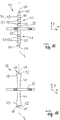
10 und11 ein schematische Seitenansicht jeweils eines weiteren Ausführungsbeispiels eines Bewehrungsstiftes, -
12 eine Prinzipdarstellung eines Verfahrensschrittes zur Herstellung des Textilbewehrungskörpers aus13 unter Verwendung einer Trenn- und/oder Formgebungseinrichtung, -
13 eine schematische Darstellung eines Ausführungsbeispiels eines Baustoffbauteils mit einer in eine Baustoffmatrix eingebetteten Textilbewehrungsanordnung, -
14-16 jeweils eine schematische Draufsicht auf weitere Ausführungsbeispiele von Baustoffbauteilen mit unterschiedlichen Geometrien bzw. Formen.
-
1 a schematic representation of a pultrusion device or a pultrusion process for producing a rod for a textile reinforcement body, -
2 a schematic, perspective cross-sectional view of a rod, -
3 a simplified schematic representation of a Diels-Alder reaction, -
4 a simplified schematic representation of a reversible cross-linking by the application of energy, -
5 and6 each a schematic representation of different embodiments of a textile reinforcement arrangement in plan view of a grid body, -
7 a perspective view of an embodiment of a reinforcing pin and its exemplary attachments to a grid body, -
8th and9 in each case an exemplary basic representation of a textile reinforcement arrangement used in a formwork for the production of a building material component, -
10 and11 1 is a schematic side view of a further exemplary embodiment of a reinforcing pin, -
12 a schematic representation of a process step for the production of thetextile reinforcement body 13 using a separating and / or shaping device, -
13 1 a schematic representation of an embodiment of a building material component with a textile reinforcement arrangement embedded in a building material matrix, -
14-16 in each case a schematic plan view of further embodiments of building material components with different geometries or shapes.
Die Erfindung betrifft eine Textilbewehrungsanordnung
Angepasst an die Gestalt des Baustoffbauteils
Die Textilbewehrungsanordnung
Der Gitterkörper weist Maschen
Der Gitterkörper
Der Gitterkörper
Bei dem in
Bei dem in
Als Kunststoff für die Kunststoffmatrix
Bei einem Ausführungsbeispiel kann die Kunststoffmatrix aus einem reversibel quervernetzten Kunststoff bestehen. Der Kunststoff weist mehrere Komponenten auf, von denen mindestens eine ein Polymer ist. Die Quervernetzung zwischen den Molekül- bzw. Polymerketten ist durch Zufuhr von Energie, insbesondere thermische Energie auftrennbar. Wenn von der Auftrennbarkeit der Quervernetzung die Rede ist, ist darunter zu verstehen, dass die Quervernetzungen der Molekülketten an der Stelle, an der die Energie zugeführt wird, nicht notwendigerweise vollständig, aber zum überwiegenden Teil durch die Energiezufuhr aufgetrennt werden. Somit sind durch die Energiezufuhr zumindest 25% oder zumindest 50% oder zumindest 70% oder zumindest 90% der hergestellten Quervernetzungen auftrennbar. Bei aufgetrennten Quervernetzungen ist das Verbundmaterial formbar bzw. biegbar Durch das Auftrennen und Wiederherstellen der Quervernetzungen können beispielsweise zwei separate Teile, beispielsweise Stäbe
Der Kunststoff der Kunststoffmatrix K hat vorzugsweise eine Glasübergangstemperatur von mindestens 50°C oder mindestens 80°C oder mindestens 90°C oder mindestens 100°C. Zusätzlich oder alternativ hat der Kunststoff der Kunststoffmatrix K insbesondere eine Glasübergangstemperatur von höchstens 130°C oder höchstens 140°C oder höchstens 150°C.The plastic of the plastic matrix K preferably has a glass transition temperature of at least 50 ° C or at least 80 ° C or at least 90 ° C or at least 100 ° C. Additionally or alternatively, the plastic of the plastic matrix K has in particular a glass transition temperature of at most 130 ° C or at most 140 ° C or at most 150 ° C.
Der Kunststoff der Kunststoffmatrix K kann eine erste Komponente mit mindestens zwei dienophilen Doppelbindungen und eine zweite Komponente mit mindestens zwei Dien-Funktionalitäten aufweisen. Die erste Komponente und/oder die zweite Komponente können dabei mehr als zwei Funktionalitäten aufweisen.The plastic of the plastic matrix K may have a first component having at least two dienophilic double bonds and a second component having at least two diene functionalities. The first component and / or the second component can have more than two functionalities.
Vorzugsweise ist die erste Komponente und/oder die zweite Komponente ein Polymer, beispielsweise ein Polyacrylat, ein Polymethacrylat, ein Polystyrol, ein Copolymer aus einem oder mehreren der vorgenannten Polymere, ein Polyacrylnitril, ein Polyether, ein Polyester, ein Polyamid, ein Polyesteramid, ein Polyurethan, ein Polycarbonat, ein amorphes und teilkristallines Poly-α-Olefin, ein Ethylen-Propylen-Dien-Kautschuk (EPDM), Ethylen-Propylen-Kautschuk (EPM), ein Polybutadiene, Acrylnitril-Butadien-Styrol (ABS), Styrol-Butadien-Kautschuk (SBR), ein Polysiloxan und/oder ein Block- und/oder Kamm- und/oder Sterncopolymer von einem oder mehren dieser Polymere.Preferably, the first component and / or the second component is a polymer, for example a polyacrylate, a polymethacrylate, a polystyrene, a copolymer of one or more of the foregoing polymers, a polyacrylonitrile, a polyether, a polyester, a polyamide, a polyesteramide Polyurethane, a polycarbonate, an amorphous and partially crystalline poly-α-olefin, an ethylene-propylene-diene rubber (EPDM), ethylene-propylene rubber (EPM), a polybutadiene, acrylonitrile-butadiene-styrene (ABS), styrene Butadiene rubber (SBR), a polysiloxane and / or a block and / or comb and / or star copolymer of one or more of these polymers.
Der Kunststoff der Kunststoffmatrix K ist im Wesentlichen inert gegenüber Wasser, alkalischen Substanzen und ist daher sowohl selbst unempfindlich gegenüber diesen Substanzen als auch möglichst diffusionsdicht um die eingebetteten Fasern vor solchen Substanzen möglichst gut zu schützen.The plastic of the plastic matrix K is substantially inert to water, alkaline substances and is therefore both insensitive to these substances and as diffusion-tight as possible in order to protect the embedded fibers against such substances as well as possible.
Die erste Komponente kann eine dienophile Komponente mit zwei dienophilen Gruppen, ein Isocyanat oder Amin mit wenigstens zwei funktionellen Gruppen pro Molekül sein. Dabei kann es sich um ein Amin, ein Diamin, eine Komponente mit einer Kohlenstoff-Schwefel-Doppelbindung und einer Elektronen aufnehmenden Gruppe, einen trifunktionalen Dithioester-Verbinder, ein difunktionales Polymer aus einer Polymerisation (ATRP), ein Isocyanurat und vorzugsweise ein Isocyanat handeln. Weiter vorzugsweise kann das Isocyanat ein Diisocyanat, wie etwa ein 2,2,4-Trimethyl-1,6-Hexamethylen-Diisocyanat (TMDI) und/oder ein 3-Isocyanotomethyl-3,5,5-Trimethylzyklohexyl-Isocyanat (Isophoron-Diisocyanat, IPDI) sein.The first component may be a dienophilic component having two dienophilic groups, one isocyanate or amine having at least two functional groups per molecule. It may be an amine, a diamine, a carbon-sulfur double bond-containing moiety and an electron-accepting moiety, a tri-functional dithioester compound, a difunctional polymer from a polymerization (ATRP), an isocyanurate, and preferably an isocyanate. More preferably, the isocyanate may be a diisocyanate such as a 2,2,4-trimethyl-1,6-hexamethylene diisocyanate (TMDI) and / or a 3-isocyanotomethyl-3,5,5-trimethylcyclohexyl isocyanate (isophorone diisocyanate , IPDI).
Als zweite Komponenten mit wenigstens zwei Dienfunktionalitäten können Diene mit Alkohol- oder Aminfunktionalität, wie etwa mehrwertige Alkohole und/oder polyfunktionale Polyamine verwendet werden. Insbesondere kann es sich um Sorbinalkohol und/oder Sorbinsäure handeln. Vorzugsweise ist das Dienophil ein Dithioester. Es ist auch möglich, Polymere, die durch Polymerisation (ATPR) erhalten wurden und mit konjugierten Diengruppen funktionalisiert sind, als zweite Komponente zu verwenden, wie zyklopentadienylterminiertes Poly-(Methyl)-Methakrylat (PMMA-Cp2).As second components having at least two diene functionalities, dienes having alcohol or amine functionality, such as polyhydric alcohols and / or polyfunctional polyamines may be used. In particular, it may be sorbic alcohol and / or sorbic acid. Preferably, the dienophile is a dithioester. It is also possible to use polymers obtained by polymerization (ATPR) and functionalized with conjugated diene groups as the second component, such as cyclopentadienyl-terminated poly (methyl) methacrylate (PMMA-Cp 2 ).
Beispiele verschiedener Kunststoffe, die als Kunststoffmatrix K verwendet werden können, sind auch in
Vorzugsweise wird als Kunststoff der Kunststoffmatrix K ein Kunststoffmaterial verwendet, das mittels einer Diels-Alder-Reaktion quervernetzbar und dessen Quervernetzung mittels einer Retro-Diels-Alder-Reaktion auftrennbar ist. Die Diels-Alder-Reaktion bzw. die Retro-Diels-Alder-Reaktion ist in
Photoreaktive Kunststoffe, die eine reversible Quervernetzung ermöglichen, enthalten beispielsweise Kumarin-Derivate, Zimtsäure, Cinnamate und Stilbene (C14H12). Zum Beispiel kann eine erste Wellenlänge λ1 oberhalb von 260 nm die Doppelbindung von Zimtsäure mit benachbarten Zinnsäuremolekülen dimerisieren, wodurch sich ein Cyklobutan bildet. Die gebildeten Cyklobutanringe können durch UV-Licht mit einer zweiten Wellenlänge λ2 von kleiner 260 nm aufgetrennt werden.Photoreactive plastics that enable reversible cross-linking include, for example, coumarin derivatives, cinnamic acid, cinnamates and stilbenes (C 14 H 12 ). For example, a first wavelength λ1 above 260 nm may dimerize the double bond of cinnamic acid with adjacent stannic acid molecules to form a cyclobutane. The formed cyclobutane rings can be separated by UV light with a second wavelength λ2 of less than 260 nm.
Photoreaktive Kunststoffe weisen zwei Komponenten auf: molekulare photochrome Gruppen, die als Schalter wirken, und permanente Netzstrukturen. Die photochromen Schalter erzeugen photoreversible kovalente Quervernetzungen, die unter Lichteinfluss abhängig von den Wellenlängen gebildet oder aufgetrennt werden. Die permanenten Netzstrukturen sind quervernetzte Polymere oder sich durchdringende Polymernetze. Geeignete Polymere sind Ethylenglycol-1-Acrylat-2-Zimtsäure und vierarmiges Stern-Polyethylenglycol mit Cinnamyllidenessigsäure und Copolymere von n-ButylAcrylat oder Butylacrylat mit Hydroxylethylmethacrylat. Photoreactive plastics have two components: molecular photochromic groups acting as switches and permanent network structures. The photochromic switches produce photoreversible covalent cross-links that are formed or separated under the influence of light depending on the wavelengths. The permanent network structures are cross-linked polymers or interpenetrating polymer networks. Suitable polymers are ethylene glycol-1-acrylate-2-cinnamic acid and four-armed star polyethylene glycol with cinnamylideneacetic acid and copolymers of n-butyl acrylate or butyl acrylate with hydroxylethyl methacrylate.
Die Textilbewehrungsanordnung
Die Bewehrungsstifte
Beispielsgemäß erstreckt sich jeder Stiftabschnitt
Die Bewehrungsstifte
Wie es in
Wenn sowohl die Bewehrungsstifte
Die Anzahl der Bewehrungsstifte
Jeder Bewehrungsstift
Bei dem in
Anstelle eines kugelförmigen Verankerungsteils
Es kann bevorzugt sein, dass sich zumindest einige der Stiftabschnitt
Ein Stiftabschnitt
Nach dem Anordnen der Textilbewehrungsanordnung
Bei diesem Vorgehen befindet sich die äußere Fläche des hergestellten Baustoffbauteils
Der im Endabschnitt
In Abwandlung zu den Darstellungen der
In
Die ersten zylindrischen Teile
Bei den Ausführungsbeispielen der Bewehrungsstifte
Anstelle eines sich verjüngenden Endabschnitts
Die Ausgestaltung des wenigstens einen Verankerungsteils
Zur Herstellung der Textilbewehrungsanordnung
Um einen oder mehrere Stiftabschnitte
Die Energiequelle
Die Trenn- und/oder Formgebungseinrichtung
Die Trenn- und/oder Formgebungseinrichtung
Die Erfindung betrifft eine Textilbewehrungsanordnung
BezugszeichenlisteLIST OF REFERENCE NUMBERS
- 2020
- TextilbewehrungsanordnungTextile reinforcement arrangement
- 2121
- Baustoffbauteilbuilding material component
- 2222
- Gitterkörpergrid body
- 2323
- erster Gitterstababschnittfirst grid bar section
- 2424
- zweiter Gitterstababschnittsecond grid bar section
- 2525
- Maschemesh
- 2626
- Stab Rod
- 2929
- TextilfaserstrangTextile fiber strand
- 3030
- Textilfaserntextile fibers
- 3131
- Pultrusionsvorrichtungpultrusion
- 3232
- Gattergate
- 3333
- SpuleKitchen sink
- 3434
- Badbath
- 3535
- Formshape
- 3636
- Abzugseinrichtungoff device
- 3737
- Trenneinrichtung separator
- 4040
- Bewehrungsstiftreinforcement pin
- 4141
- Stiftabschnittpin section
- 4242
- Befestigungsmittelfastener
- 42a42a
- Netznetwork
- 4343
- Verankerungsteilanchoring part
- 4444
- äußeres Ende des Stiftabschnittsouter end of the pin section
- 4545
- Endabschnittend
- 4646
- Schalungformwork
- 4747
- Schalungswand formwork wall
- 5050
- erste zylindrische Teilefirst cylindrical parts
- 5151
- zweite zylindrische Teilesecond cylindrical parts
- 5252
- Ringstufe annular step
- 5555
- Trenn- und/oder FormgebungseinrichtungSeparating and / or shaping device
- 5656
- Anlageteilplant part
- 5757
- Anlageflächecontact surface
- 5858
- Trenn- und/oder FormgebungseinheitSeparating and / or shaping unit
- 5959
- Schneidecutting edge
- 6060
- Energiequelleenergy
- 6161
- Trennstelleseparation point
- 6262
- Einstelleinrichtungadjustment
- 6363
- Aufnahmebereich reception area
- BB
- Baustoffbuilding material
- KK
- KunststoffmatrixPlastic matrix
- LL
- Längsachselongitudinal axis
- xx
- erste Richtungfirst direction
- yy
- zweite Richtungsecond direction
- zz
- dritte Richtungthird direction
ZITATE ENTHALTEN IN DER BESCHREIBUNG QUOTES INCLUDE IN THE DESCRIPTION
Diese Liste der vom Anmelder aufgeführten Dokumente wurde automatisiert erzeugt und ist ausschließlich zur besseren Information des Lesers aufgenommen. Die Liste ist nicht Bestandteil der deutschen Patent- bzw. Gebrauchsmusteranmeldung. Das DPMA übernimmt keinerlei Haftung für etwaige Fehler oder Auslassungen.This list of the documents listed by the applicant has been generated automatically and is included solely for the better information of the reader. The list is not part of the German patent or utility model application. The DPMA assumes no liability for any errors or omissions.
Zitierte PatentliteraturCited patent literature
- DE 102011087226 A1 [0002]DE 102011087226 A1 [0002]
- US 6612085 B2 [0004]US 6612085 B2 [0004]
- US 6023903 A [0005]US 6023903 A [0005]
- EP 0292572 A1 [0006]EP 0292572 A1 [0006]
- DE 4009986 A1 [0007]DE 4009986 A1 [0007]
- DE 102010001987 A1 [0049]DE 102010001987 A1 [0049]
Claims (19)
Priority Applications (3)
| Application Number | Priority Date | Filing Date | Title |
|---|---|---|---|
| DE102017120624.8A DE102017120624A1 (en) | 2017-09-07 | 2017-09-07 | Textile reinforcement arrangement, method for its production and separating and / or shaping device for use in this method |
| EP18765076.7A EP3678853A1 (en) | 2017-09-07 | 2018-08-30 | Textile reinforcing arrangement and method for producing same |
| PCT/EP2018/073375 WO2019048337A1 (en) | 2017-09-07 | 2018-08-30 | TEXTILE REINFORCEMENT ARRANGEMENT AND METHOD FOR THE PRODUCTION THEREOF |
Applications Claiming Priority (1)
| Application Number | Priority Date | Filing Date | Title |
|---|---|---|---|
| DE102017120624.8A DE102017120624A1 (en) | 2017-09-07 | 2017-09-07 | Textile reinforcement arrangement, method for its production and separating and / or shaping device for use in this method |
Publications (1)
| Publication Number | Publication Date |
|---|---|
| DE102017120624A1 true DE102017120624A1 (en) | 2019-03-07 |
Family
ID=63490452
Family Applications (1)
| Application Number | Title | Priority Date | Filing Date |
|---|---|---|---|
| DE102017120624.8A Withdrawn DE102017120624A1 (en) | 2017-09-07 | 2017-09-07 | Textile reinforcement arrangement, method for its production and separating and / or shaping device for use in this method |
Country Status (3)
| Country | Link |
|---|---|
| EP (1) | EP3678853A1 (en) |
| DE (1) | DE102017120624A1 (en) |
| WO (1) | WO2019048337A1 (en) |
Cited By (2)
| Publication number | Priority date | Publication date | Assignee | Title |
|---|---|---|---|---|
| EP4431672A1 (en) | 2023-03-16 | 2024-09-18 | Carbon 360 GmbH | Concrete reinforcement grid element and component |
| DE102023203726A1 (en) * | 2023-04-24 | 2024-10-24 | Sgl Carbon Se | REINFORCEMENT UNIT |
Citations (10)
| Publication number | Priority date | Publication date | Assignee | Title |
|---|---|---|---|---|
| EP0292572A1 (en) | 1986-12-11 | 1988-11-30 | Nitto Denko Corporation | Process for manufacturing fiber-reinforced resin wire |
| DE4009986A1 (en) | 1990-03-28 | 1991-10-02 | Schoeck Bauteile Gmbh | Rod-shaped reinforcement component - has one or more circular bends flattened at bend point by rolling |
| EP0227207B1 (en) * | 1985-12-26 | 1992-12-23 | SHIMIZU CONSTRUCTION Co. LTD. | Concrete reinforcing unit |
| US6023903A (en) | 1998-07-27 | 2000-02-15 | Surface Technologies, Inc. | Non-corrosive reinforcing member having bendable flanges |
| US6612085B2 (en) | 2000-01-13 | 2003-09-02 | Dow Global Technologies Inc. | Reinforcing bars for concrete structures |
| DE102010001987A1 (en) | 2010-02-16 | 2011-08-18 | Evonik Röhm GmbH, 64293 | Functional materials with reversible crosslinking |
| CN202530631U (en) * | 2012-04-16 | 2012-11-14 | 周学义 | Grids capable of enhancing structure and intensity of mineral wool board |
| DE102011087226A1 (en) | 2011-11-28 | 2013-05-29 | Evonik Degussa Gmbh | Pseudo-thermoplastic, self-crosslinking composites |
| CN203867074U (en) * | 2014-06-03 | 2014-10-08 | 南京工业大学 | Three-dimensional fiber grid rib reinforced concrete structural member |
| DE102013015434A1 (en) * | 2013-09-18 | 2015-04-02 | Groz-Beckert Kg | Spacer for a reinforcement layer, reinforcement arrangement for a concrete component and method for producing a reinforcement arrangement |
Family Cites Families (6)
| Publication number | Priority date | Publication date | Assignee | Title |
|---|---|---|---|---|
| JPH03293452A (en) * | 1990-04-12 | 1991-12-25 | Ohbayashi Corp | Fibre-reinforced concrete member |
| JPH0587115U (en) * | 1992-04-30 | 1993-11-22 | 株式会社有沢製作所 | Concrete reinforcement |
| DE102007042700A1 (en) * | 2007-09-07 | 2009-03-12 | Walter Gutjahr | Heavy duty pavement producing method for use during reconstruction or renovation of floor space, involves applying pavement material on underground connected with lattice structure in preset layer thickness |
| DE102009043006B4 (en) * | 2009-09-28 | 2018-02-15 | Norbert Uhlmann | Flooring and methods of making or renovating floors |
| DE102012004787B4 (en) * | 2012-03-06 | 2016-08-11 | Technische Universität Dresden | Spacer insert for insertion into components to be produced with a base material with integrated textile reinforcement layers |
| DE102015013402A1 (en) * | 2015-10-19 | 2017-04-20 | Rheinisch-Westfälische Technische Hochschule (Rwth) Aachen | Process for the production of a fiber-reinforced plastic component prepared for the welding of a metal component and a metallic joining partner for it |
-
2017
- 2017-09-07 DE DE102017120624.8A patent/DE102017120624A1/en not_active Withdrawn
-
2018
- 2018-08-30 WO PCT/EP2018/073375 patent/WO2019048337A1/en not_active Ceased
- 2018-08-30 EP EP18765076.7A patent/EP3678853A1/en not_active Withdrawn
Patent Citations (10)
| Publication number | Priority date | Publication date | Assignee | Title |
|---|---|---|---|---|
| EP0227207B1 (en) * | 1985-12-26 | 1992-12-23 | SHIMIZU CONSTRUCTION Co. LTD. | Concrete reinforcing unit |
| EP0292572A1 (en) | 1986-12-11 | 1988-11-30 | Nitto Denko Corporation | Process for manufacturing fiber-reinforced resin wire |
| DE4009986A1 (en) | 1990-03-28 | 1991-10-02 | Schoeck Bauteile Gmbh | Rod-shaped reinforcement component - has one or more circular bends flattened at bend point by rolling |
| US6023903A (en) | 1998-07-27 | 2000-02-15 | Surface Technologies, Inc. | Non-corrosive reinforcing member having bendable flanges |
| US6612085B2 (en) | 2000-01-13 | 2003-09-02 | Dow Global Technologies Inc. | Reinforcing bars for concrete structures |
| DE102010001987A1 (en) | 2010-02-16 | 2011-08-18 | Evonik Röhm GmbH, 64293 | Functional materials with reversible crosslinking |
| DE102011087226A1 (en) | 2011-11-28 | 2013-05-29 | Evonik Degussa Gmbh | Pseudo-thermoplastic, self-crosslinking composites |
| CN202530631U (en) * | 2012-04-16 | 2012-11-14 | 周学义 | Grids capable of enhancing structure and intensity of mineral wool board |
| DE102013015434A1 (en) * | 2013-09-18 | 2015-04-02 | Groz-Beckert Kg | Spacer for a reinforcement layer, reinforcement arrangement for a concrete component and method for producing a reinforcement arrangement |
| CN203867074U (en) * | 2014-06-03 | 2014-10-08 | 南京工业大学 | Three-dimensional fiber grid rib reinforced concrete structural member |
Non-Patent Citations (2)
| Title |
|---|
| CN 202530631 U – Maschinenübersetzung, über Google Patents [online] abgerufen am 25.06.2018 * |
| CN 203867074 U – Maschinenübersetzung, über Google Patents [online] abgerufen am 25.06.2018 * |
Cited By (3)
| Publication number | Priority date | Publication date | Assignee | Title |
|---|---|---|---|---|
| EP4431672A1 (en) | 2023-03-16 | 2024-09-18 | Carbon 360 GmbH | Concrete reinforcement grid element and component |
| DE102023001132A1 (en) * | 2023-03-16 | 2024-09-19 | Carbon 360 GmbH | Concrete reinforcement mesh element and component |
| DE102023203726A1 (en) * | 2023-04-24 | 2024-10-24 | Sgl Carbon Se | REINFORCEMENT UNIT |
Also Published As
| Publication number | Publication date |
|---|---|
| EP3678853A1 (en) | 2020-07-15 |
| WO2019048337A1 (en) | 2019-03-14 |
Similar Documents
| Publication | Publication Date | Title |
|---|---|---|
| EP3426860B1 (en) | Concrete component having a reinforcing element, method for producing same and method for bending a reinforcing bar of a reinforcing element | |
| DE60303348T2 (en) | Process for producing a monolithic, double-walled and heat-resistant composite part and composite part produced thereafter | |
| EP2666922B2 (en) | Textile-reinforced concrete element | |
| WO2019092169A1 (en) | Reinforcement of 3d-printed concrete bodies | |
| WO2005061813A1 (en) | Anchoring for pre-tensioned and/or stressed tensile elements | |
| DE2757965A1 (en) | THROTTLE TRANSMISSION ELEMENT AND METHOD FOR MANUFACTURING IT | |
| EP3408532B1 (en) | Rotor blade of wind turbine comprising a spar cap and production method | |
| EP3418465A1 (en) | Method for producing a textile reinforced building material component and clamping device for same | |
| WO2019092162A1 (en) | Reinforcement of 3d-printed concrete bodies | |
| EP3114288B1 (en) | Reinforcing mesh for concrete construction | |
| DE102006008728B3 (en) | Producing a three-dimensional framework useful for making structural components of aircraft comprises applying heat and force to a two-dimensional lattice of rods | |
| DE102017120624A1 (en) | Textile reinforcement arrangement, method for its production and separating and / or shaping device for use in this method | |
| EP1331327A1 (en) | Reinforcing device | |
| EP3599320A1 (en) | Reinforcing bar and method for its production | |
| EP2209952B1 (en) | Spacer and structural component for producing a wall construction, and method and device | |
| EP3845354B1 (en) | Method of manufacturing segments for a tower, prestressed segment, tower ring, tower and wind turbine | |
| DE102016101663A1 (en) | Holmgurt and manufacturing process | |
| DE102011110915A1 (en) | Method for determining material characteristics data of energy absorbing element for use in vehicle to absorb energy during collision, involves triggering specimen when load is input in middle region of front end of specimen | |
| EP4022144A1 (en) | Method for producing a textile transverse force reinforcement, supporting device, transverse force reinforcement, concrete component and thread placement data file | |
| WO2017067623A1 (en) | Method for producing a component consisting of a fibre-reinforced plastic and prepared for the welding of a metal component, and metal joining partner therefor | |
| EP3610092B1 (en) | Reinforcing rod for insertion in a concrete matrix and production method therefor, a reinforcement system made from a plurality of reinforcing rods, and a concrete component | |
| DE102010032915A1 (en) | Plastic strand for forming rope for concrete used as building material, has several radial projections which are formed and spaced apart from each other, and glass fibers provided through radial projections | |
| DE19604275C2 (en) | Method of manufacturing a component | |
| WO2008095211A1 (en) | Disc-shaped body for fibres | |
| AT525587A1 (en) | Method for producing a fiber laminate, a fiber laminate and a use of a fiber laminate |
Legal Events
| Date | Code | Title | Description |
|---|---|---|---|
| R012 | Request for examination validly filed | ||
| R016 | Response to examination communication | ||
| R081 | Change of applicant/patentee |
Owner name: SOLIDIAN GMBH, DE Free format text: FORMER OWNER: GROZ-BECKERT KG, 72458 ALBSTADT, DE |
|
| R082 | Change of representative |
Representative=s name: RUEGER ABEL PATENTANWAELTE PARTGMBB, DE |
|
| R119 | Application deemed withdrawn, or ip right lapsed, due to non-payment of renewal fee |