DE102017113945A1 - Modular optical modular system for near-focal beam density distributions with alternating beam density profile - Google Patents
Modular optical modular system for near-focal beam density distributions with alternating beam density profile Download PDFInfo
- Publication number
- DE102017113945A1 DE102017113945A1 DE102017113945.1A DE102017113945A DE102017113945A1 DE 102017113945 A1 DE102017113945 A1 DE 102017113945A1 DE 102017113945 A DE102017113945 A DE 102017113945A DE 102017113945 A1 DE102017113945 A1 DE 102017113945A1
- Authority
- DE
- Germany
- Prior art keywords
- optical
- stop
- fine thread
- housing
- focusing
- Prior art date
- Legal status (The legal status is an assumption and is not a legal conclusion. Google has not performed a legal analysis and makes no representation as to the accuracy of the status listed.)
- Granted
Links
- 230000003287 optical effect Effects 0.000 title claims abstract description 130
- 238000009826 distribution Methods 0.000 title claims abstract description 18
- 230000001131 transforming effect Effects 0.000 claims abstract 2
- 239000000835 fiber Substances 0.000 claims description 37
- 239000013307 optical fiber Substances 0.000 claims description 8
- 238000010276 construction Methods 0.000 claims description 3
- 230000000712 assembly Effects 0.000 description 6
- 238000000429 assembly Methods 0.000 description 6
- 238000000034 method Methods 0.000 description 4
- 230000002902 bimodal effect Effects 0.000 description 3
- 235000012489 doughnuts Nutrition 0.000 description 3
- 238000004519 manufacturing process Methods 0.000 description 3
- 230000005540 biological transmission Effects 0.000 description 2
- 230000008878 coupling Effects 0.000 description 2
- 238000010168 coupling process Methods 0.000 description 2
- 238000005859 coupling reaction Methods 0.000 description 2
- 230000001419 dependent effect Effects 0.000 description 2
- BUHVIAUBTBOHAG-FOYDDCNASA-N (2r,3r,4s,5r)-2-[6-[[2-(3,5-dimethoxyphenyl)-2-(2-methylphenyl)ethyl]amino]purin-9-yl]-5-(hydroxymethyl)oxolane-3,4-diol Chemical compound COC1=CC(OC)=CC(C(CNC=2C=3N=CN(C=3N=CN=2)[C@H]2[C@@H]([C@H](O)[C@@H](CO)O2)O)C=2C(=CC=CC=2)C)=C1 BUHVIAUBTBOHAG-FOYDDCNASA-N 0.000 description 1
- 230000015572 biosynthetic process Effects 0.000 description 1
- 230000003111 delayed effect Effects 0.000 description 1
- 238000006073 displacement reaction Methods 0.000 description 1
- 235000021197 fiber intake Nutrition 0.000 description 1
- 238000003384 imaging method Methods 0.000 description 1
- 230000002093 peripheral effect Effects 0.000 description 1
- 230000010363 phase shift Effects 0.000 description 1
- 239000011295 pitch Substances 0.000 description 1
- 230000005855 radiation Effects 0.000 description 1
- 239000007787 solid Substances 0.000 description 1
- 230000007704 transition Effects 0.000 description 1
Images


Classifications
-
- G—PHYSICS
- G02—OPTICS
- G02B—OPTICAL ELEMENTS, SYSTEMS OR APPARATUS
- G02B27/00—Optical systems or apparatus not provided for by any of the groups G02B1/00 - G02B26/00, G02B30/00
- G02B27/09—Beam shaping, e.g. changing the cross-sectional area, not otherwise provided for
- G02B27/0927—Systems for changing the beam intensity distribution, e.g. Gaussian to top-hat
-
- G—PHYSICS
- G02—OPTICS
- G02B—OPTICAL ELEMENTS, SYSTEMS OR APPARATUS
- G02B27/00—Optical systems or apparatus not provided for by any of the groups G02B1/00 - G02B26/00, G02B30/00
- G02B27/09—Beam shaping, e.g. changing the cross-sectional area, not otherwise provided for
- G02B27/0938—Using specific optical elements
- G02B27/095—Refractive optical elements
- G02B27/0955—Lenses
-
- G—PHYSICS
- G02—OPTICS
- G02B—OPTICAL ELEMENTS, SYSTEMS OR APPARATUS
- G02B27/00—Optical systems or apparatus not provided for by any of the groups G02B1/00 - G02B26/00, G02B30/00
- G02B27/09—Beam shaping, e.g. changing the cross-sectional area, not otherwise provided for
- G02B27/0938—Using specific optical elements
- G02B27/0988—Diaphragms, spatial filters, masks for removing or filtering a part of the beam
-
- G—PHYSICS
- G02—OPTICS
- G02B—OPTICAL ELEMENTS, SYSTEMS OR APPARATUS
- G02B27/00—Optical systems or apparatus not provided for by any of the groups G02B1/00 - G02B26/00, G02B30/00
- G02B27/09—Beam shaping, e.g. changing the cross-sectional area, not otherwise provided for
- G02B27/0938—Using specific optical elements
- G02B27/0994—Fibers, light pipes
-
- G—PHYSICS
- G02—OPTICS
- G02B—OPTICAL ELEMENTS, SYSTEMS OR APPARATUS
- G02B27/00—Optical systems or apparatus not provided for by any of the groups G02B1/00 - G02B26/00, G02B30/00
- G02B27/30—Collimators
-
- G—PHYSICS
- G02—OPTICS
- G02B—OPTICAL ELEMENTS, SYSTEMS OR APPARATUS
- G02B7/00—Mountings, adjusting means, or light-tight connections, for optical elements
- G02B7/003—Alignment of optical elements
-
- G—PHYSICS
- G02—OPTICS
- G02B—OPTICAL ELEMENTS, SYSTEMS OR APPARATUS
- G02B7/00—Mountings, adjusting means, or light-tight connections, for optical elements
- G02B7/02—Mountings, adjusting means, or light-tight connections, for optical elements for lenses
- G02B7/022—Mountings, adjusting means, or light-tight connections, for optical elements for lenses lens and mount having complementary engagement means, e.g. screw/thread
-
- G—PHYSICS
- G02—OPTICS
- G02B—OPTICAL ELEMENTS, SYSTEMS OR APPARATUS
- G02B7/00—Mountings, adjusting means, or light-tight connections, for optical elements
- G02B7/02—Mountings, adjusting means, or light-tight connections, for optical elements for lenses
- G02B7/023—Mountings, adjusting means, or light-tight connections, for optical elements for lenses permitting adjustment
-
- G—PHYSICS
- G02—OPTICS
- G02B—OPTICAL ELEMENTS, SYSTEMS OR APPARATUS
- G02B7/00—Mountings, adjusting means, or light-tight connections, for optical elements
- G02B7/02—Mountings, adjusting means, or light-tight connections, for optical elements for lenses
- G02B7/04—Mountings, adjusting means, or light-tight connections, for optical elements for lenses with mechanism for focusing or varying magnification
Landscapes
- Physics & Mathematics (AREA)
- General Physics & Mathematics (AREA)
- Optics & Photonics (AREA)
- Optical Couplings Of Light Guides (AREA)
- Lenses (AREA)
- Lens Barrels (AREA)
- Mounting And Adjusting Of Optical Elements (AREA)
Abstract
Die Erfindung betrifft ein Baukastensystem von optischen Bauelementen (1.1, 1.2, 10), umfassend eine Phasenplatte (1.1), eine fokussierende Linse (1.2) und einen Strahlaufweiter (10). Die optischen Bauelemente (1.1, 1.2, 10) sind jeweils in einem Gehäuse (2) gefasst, welches ein erstes und ein zweites Feingewinde (2.1, 2.3) aufweist. Das erste und zweite Feingewinde (2.1, 2.3) sind miteinander verschraubbar ausgebildet. Die gefasste Phasenplatte (1.1) ist so eingerichtet, dass sie mit einer im Strahlengang nachgeordneten asphärischen fokussierenden Linse (1.2) einen fokussierenden Strahlformer (1) zur Transformation von zur optischen Achse (X) kollimiertem Licht einer Wellenlänge und einer Eintrittsstrahldichteverteilung mit einem Gauß-Profil in eine Austrittsstrahldichteverteilung (LS) mit einem alternierenden Strahldichteprofil (TP, TP', TP", DP, BP) in mindestens einer Bildebene (B1 bis B5) bildet.

Description
Die Erfindung betrifft ein optisches Baukastensystem zur Erzeugung von fokussierten Austrittsstrahlen, deren Strahldichte in einem Fokusbereich um eine Fokusebene oder Brennebene rotationssymmetrisch um die optisch
Das Strahldichteprofil kann in einem zentralen Bereich um die optische Achse konstant sein und beidseits des zentralen Bereichs steil auf Null abfallen. Ein derartiges Strahldichteprofil soll im Folgenden als Top-Hat-Profil bezeichnet werden.The radiance profile may be constant in a central region about the optical axis and drop sharply to zero on both sides of the central region. Such a radiance profile is to be referred to below as the top hat profile.
Das Strahldichteprofil kann bimodal ausgebildet sein, wobei beidseits eines auf der optischen Achse liegenden Strahldichteminimums jeweils ein Strahldichtemaximum angeordnet ist. Ein derartiges Strahldichteprofil soll im Folgenden als Donut-Profil bezeichnet werden.The radiance profile can be formed bimodal, wherein a radiance maximum is arranged on both sides of a radiance minimum lying on the optical axis. Such a radiance profile is to be referred to below as a donut profile.
Das Strahldichteprofil kann auch unimodal ausgebildet sein, wobei ein einziges Strahldichtemaximum auf der optischen Achse liegt. Ein derartiges Strahldichteprofil soll im Folgenden als Beam-Waist-Profil bezeichnet werden.The radiance profile can also be formed unimodal, wherein a single radiance maximum lies on the optical axis. Such a radiance profile is to be referred to below as a beam waist profile.
Die Gesamtheit derartiger Strahldichteprofile soll im Folgenden als alternierende Strahldichteprofile bezeichnet werden, da derartige Strahldichteprofile im Wesentlichen zwischen einem oberen Strahldichtewert und einem unteren Strahldichtewert alternieren.The totality of such radiance profiles is to be referred to below as alternating radiance profiles, since such radiance profiles substantially alternate between an upper radiance value and a lower radiance value.
Die Erfindung ist auch auf fokussierende Strahlformer gerichtet, mit denen verschiedene alternierende Strahldichteprofile in verschiedenen Bildebenen erzeugt werden, die entlang der optischen Achse um einen Fokuspunkt und jeweils senkrecht zur optischen Achse angeordnet sind.The invention is also directed to focusing beamformers, with which different alternating beam density profiles are generated in different image planes, which are arranged along the optical axis about a focal point and each perpendicular to the optical axis.
Aus dem Stand der Technik sind fokussierende Strahlformer oder Focus Beam Shaper (FBS) bekannt, mit denen Bündel von kollimierten Eintrittsstrahlen, deren Verteilung in einer zur optischen Achse senkrechten Eintrittsebene durch eine Eintrittsstrahldichteverteilung mit einem rotationssymmetrischen Gaußprofil bestimmt ist, in Austrittsstrahlen transformiert werden, die in einer Fokusebene fokussiert sind, wobei die Strahldichteverteilung in der Fokusebene einem Top-Hat-Profil folgt.Focussing beam shapers or Focus Beam Shaper (FBS) are known from the prior art, with which bundles of collimated entrance beams whose distribution in an entry plane perpendicular to the optical axis is determined by an entrance beam density distribution with a rotationally symmetric Gaussian profile are transformed into exit beams, which in a focus plane are focused, the beam density distribution in the focal plane follows a top hat profile.
Ferner sind Faserkollimatoren bekannt, mit denen Licht, das aus der Austrittsfläche einer optischen Faser in einem Raumwinkelbereich divergent austritt, der von der numerischen Apertur der optischen Faser bestimmt wird, kollimiert wird.Further, fiber collimators are known for collimating light that diverges from the exit surface of an optical fiber in a solid angle range determined by the numerical aperture of the optical fiber.
Aus dem Stand der Technik sind ferner Strahlaufweiter bekannt, mit denen der Durchmesser eines kollimierten Strahlenbündels verändert werden kann.Furthermore, beam expanders are known from the prior art with which the diameter of a collimated beam can be changed.
Zudem sind Verfahren und Vorrichtungen bekannt, mit denen optische Bauelemente, beispielsweise Strahlformer, Faserkollimatoren und/oder Strahlaufweiter miteinander verbunden oder gegeneinander fixiert sowie optisch justiert werden können. Beispielsweise sind optische Bänke bekannt, die Aufnahmevorrichtungen zur Aufnahme optischer Bauelemente sowie Fixiervorrichtungen umfassen, mittels derer solche Aufnahmevorrichtungen gegeneinander fixierbar sind. Es sind auch Verfahren bekannt, mit denen optische Bauelemente mit Hilfe von Autokollimationsfernrohren zueinander zentriert und so ausgerichtet werden können, dass die optischen Achsen der einzelnen Bauelemente fluchten.In addition, methods and devices are known with which optical components, such as beam shaper, fiber collimators and / or beam expander connected or fixed against each other and can be optically adjusted. For example, optical benches are known which comprise receiving devices for receiving optical components and fixing devices by means of which such receiving devices can be fixed relative to one another. Methods are also known with which optical components can be centered relative to each other with the aid of autocollimation telescopes and aligned in such a way that the optical axes of the individual components are aligned.
Der Erfindung liegt die Aufgabe zu Grunde, ein modulares optisches Baukastensystem anzugeben, das eine geringe Zahl von Bauelementtypen umfasst, die von einer bestimmten Eintrittsstrahlenverteilung und einer bestimmten Austrittsstrahlenverteilung unabhängig standardisiert bereitgestellt sind und mit denen für eine große Zahl von Eintrittsstrahldichteverteilungen mit einem Gauß-Profil Austrittsstrahlen erzeugbar sind, die eine Strahldichteverteilung mit einem alternierendem Strahldichteprofil in einer austrittsseitig angeordneten Bildebene bewirken. Ferner liegt der Erfindung die Aufgabe zu Grunde, ein solches modulares optisches Baukastensystem so anzugeben, dass optische Bauelemente gleicher und/oder unterschiedlicher Bauelementtypen leichter gegeneinander fixierbar und/oder optisch justierbar sind.The invention has for its object to provide a modular optical modular system comprising a small number of device types, which are provided independently standardized by a certain entrance beam distribution and a certain exit beam distribution and with which for a large number of entrance beam density distributions with a Gaussian profile exit jets can be generated, which cause a beam density distribution with an alternating density profile in an image plane arranged on the exit side. Furthermore, the invention is based on the object to provide such a modular optical modular system so that optical components of the same and / or different types of components are easier to fix against each other and / or optically adjustable.
Die Aufgabe wird erfindungsgemäß gelöst durch ein modulares optisches Baukastensystem mit den Merkmalen des Anspruchs 1.The object is achieved by a modular optical modular system having the features of
Vorteilhafte Ausgestaltungen der Erfindung sind Gegenstand der Unteransprüche.Advantageous embodiments of the invention are the subject of the dependent claims.
Das Baukastensystem umfasst als gefasste optische Bauelemente mindestens eine gefasste Phasenplatte und mindestens eine gefasste fokussierende Linse. In einer Ausführungsform der Erfindung ist die fokussierende Linse als fokussierende asphärische Linse ausgebildet. Die mindestens eine gefasste Phasenplatte ist so eingerichtet, dass sie mit mindestens einer im Strahlengang nachgeordneten gefassten asphärischen fokussierenden Linse zu einem fokussierenden Strahlformer verbindbar ist.The modular system comprises as captured optical components at least one mounted phase plate and at least one focused focusing lens. In one embodiment of the invention, the focusing lens is designed as a focusing aspherical lens. The at least one composed phase plate is set up such that it can be connected to at least one aspherical focused focusing lens disposed in the beam path to form a focusing beam former.
Ein solcher fokussierender Strahlformer transformiert zu einer optischen Achse kollimiertes Licht einer Wellenlänge und einer Eintrittsstrahldichteverteilung mit einem Gauß-Profil in eine Austrittsstrahldichteverteilung mit einem alternierenden Strahldichteprofil in mindestens einer Bildebene, die senkrecht zur optischen Achse liegt. Ein Strahldichteprofil erfasst den Strahldichteverlauf in einer Bildebene entlang einer Profilrichtung senkrecht auf der optischen Achse. Ein alternierendes Strahldichteprofil weist entlang der Profilrichtung einen unimodalen, einen bimodalen oder einen Strahldichteverlauf auf, der in einem zentralen Bereich um die optische Achse näherungsweise konstant ist und beidseits dieses zentralen Bereichs steil auf Null abfällt. Such a focusing beamformer transforms to an optical axis collimated light of a wavelength and an entrance beam density distribution having a Gaussian profile into an exit beam density distribution with an alternating beam density profile in at least one image plane perpendicular to the optical axis. A radiance profile detects the radiance profile in an image plane along a profile direction perpendicular to the optical axis. An alternating beam density profile has a unimodal, a bimodal or a beam density profile along the profile direction, which is approximately constant in a central region about the optical axis and steeply drops to zero on both sides of this central region.
Das Baukastensystem umfasst ferner mindestens einen Strahlaufweiter zur beugungsbegrenzten Veränderung des Durchmessers eines zur optischen Achse kollimierten Strahlenbündels monochromatischen Lichts der gleichen Wellenlänge.The modular system further comprises at least one beam expander for diffraction-limited change in the diameter of a collimated to the optical axis beam of monochromatic light of the same wavelength.
Die gefassten optischen Bauelemente sind jeweils in einem hülsenförmigen, koaxial zur optischen Achse angeordneten Gehäuse gefasst, wobei konzentrisch zur optischen Achse an einem ersten Ende des Gehäuses ein ringförmiger erster Anschlag und ein erstes Feingewinde sowie an einem gegenüberliegenden zweiten Ende des Gehäuses ein ringförmiger zweiter Anschlag und ein zweites Feingewinde angeordnet sind. Die Anschläge und die Feingewinde sind passend geformt und angeordnet, so dass das zweite Feingewinde eines ersten gefassten optischen Bauelements mit dem ersten Feingewinde eines zweiten optischen Bauelements bis in eine Anschlagposition verschraubbar ist, in welcher der zweite Anschlag des Gehäuses des ersten optischen Bauelements den ersten Anschlag des Gehäuses des zweiten optischen Bauelements kontaktiert. In dieser Anschlagposition sind die verschraubten gefassten optischen Bauelemente so ausgerichtet, dass ihre optischen Achsen innerhalb der beugungsbegrenzten Divergenz fluchten.The captured optical components are each in a sleeve-shaped, arranged coaxially to the optical axis housing, wherein concentric with the optical axis at a first end of the housing, an annular first stop and a first fine thread and at an opposite second end of the housing, an annular second stop and a second fine thread are arranged. The stops and the fine threads are suitably shaped and arranged so that the second fine thread of a first mounted optical component with the first fine thread of a second optical component can be screwed into a stop position in which the second stop of the housing of the first optical component, the first stop contacted the housing of the second optical component. In this stop position, the threaded captive optical components are aligned so that their optical axes are aligned within the diffraction-limited divergence.
In einer Ausführungsform der Erfindung ist mindestens ein Strahlaufweiter für eine Anordnung im Strahlengang eines fokussierenden Strahlformers zwischen einer gefassten Phasenplatte und einer fokussierenden asphärischen Linse eingerichtet. Mittels des zwischen der Phasenplatte und der fokussierenden asphärischen Linse angeordneten Strahlaufweiters kann der aus der Phasenplatte austretende Strahldurchmesser an den optisch wirksamen Durchmesser der fokussierenden asphärischen Linse angepasst werden. Ein Vorteil dieser Ausführungsform besteht darin, dass durch die Hinzunahme und Anordnung des Strahlaufweiters fokussierende Strahlformer für verschiedene Durchmesser von kollimierten Eingangsstrahlenbündeln gebildet werden können. Somit ist es möglich, mit einer sehr kleinen Zahl unterschiedlicher gefasster optischer Bauelemente ein Baukastensystem für die Herstellung von fokussierenden Strahlformern herzustellen, die für besonders viele Anwendungen geeignet sind.In one embodiment of the invention, at least one beam expander is arranged for an arrangement in the beam path of a focusing beam former between a captive phase plate and a focusing aspherical lens. By means of the arranged between the phase plate and the focusing aspherical lens beam expander emerging from the phase plate beam diameter can be adapted to the optically effective diameter of the focusing aspherical lens. An advantage of this embodiment is that by adding and arranging the beam expander, focusing beamformers for different diameters of collimated input beams can be formed. Thus, it is possible to produce a modular system for the production of focusing beamformers with a very small number of different shaped optical components, which are suitable for a particularly large number of applications.
In einer Ausführungsform der Erfindung ist die fokussierende Linse eines fokussierenden Strahlformers in einem erfindungsgemäßen Gehäuse so gefasst und angeordnet, dass verschiedene Linsen unterschiedlicher Brennweite und numerischer Apertur leicht gegeneinander ausgetauscht und mit ein und derselben Phasenplatte kombiniert werden können. Dadurch ist es möglich, alternierende Strahldichteprofile verschiedener radialer Ausdehnung in Brennebenen mit verschiedenen Abständen oder Brennweiten durch einfachen Austausch der austrittsseitigen fokussierenden Linse zu erzeugen.In one embodiment of the invention, the focusing lens of a focusing beam former in a housing according to the invention is so arranged and arranged that different lenses of different focal length and numerical aperture can be easily interchanged and combined with one and the same phase plate. This makes it possible to generate alternating radiance profiles of different radial extent in focal planes with different distances or focal lengths by simply exchanging the exit-side focusing lens.
In vorteilhafter Weise erlaubt die erfindungsgemäße Anordnung optischer Bauelemente in Gehäusen die Herstellung von optischen Baugruppen durch einfaches Verschrauben. Damit entfallen weitere aufwändige Justageschritte und es kann zuverlässig durch Kombination der gefassten optischen Bauelemente eine Vielzahl von optischen Baugruppen mit hochgenauer, beugungsbegrenzter optischer Wirkung hergestellt werden.Advantageously, the inventive arrangement of optical components in housings allows the production of optical assemblies by simply screwing. This eliminates further elaborate Justageschritte and it can be reliably produced by combining the captured optical components, a variety of optical assemblies with high-precision, diffraction-limited optical effect.
Ein weiterer Vorteil des Baukastensystems besteht darin, dass durch Verschrauben eines fokussierenden Strahlformers mit mindestens einem, austrittsseitig zum fokussierenden Strahlformer angeordneten und ebenfalls in einem erfindungsgemäßen Gehäuse gefassten Strahlaufweiters die radiale Ausdehnung des alternierenden Strahldichteprofils leicht verändert werden kann.A further advantage of the modular system is that the radial extent of the alternating beam density profile can be easily changed by screwing a focusing beam former with at least one beam expander arranged on the outlet side to the focusing beam former and also enclosed in a housing according to the invention.
Zudem ist es in vorteilhafter Weise möglich, mittels eines gefassten Strahlaufweiters den Durchmesser eines aus einer gefassten Phasenplatte austretenden Strahls an die im Strahlengang nachgeordnete gefasste fokussierende Linse anzupassen. Ein solcher, aus einer gefassten Phasenplatte, einem gefassten Strahlaufweiter und einer gefassten fokussierenden Linse bestehender fokussierender Strahlformer ermöglicht die Nutzung von fokussierenden Linsen mit einer möglichst kurzen Brennweite bei einer vorgegebenen numerischen Apertur und ermöglicht somit eine besonders kurze Baulänge.In addition, it is advantageously possible to adapt the diameter of a beam emerging from a composed phase plate to the focused focusing lens disposed in the beam path by means of a captured beam expander. Such, consisting of a composed phase plate, a fixed beam expander and a focused focusing lens existing focusing beam shaper allows the use of focusing lenses with the shortest possible focal length at a given numerical aperture and thus allows a very short overall length.
Zudem kann die eintrittsseitig an einem fokussierenden Strahlformer angeordnete gefasste Phasenplatte mit mindestens einem eintrittsseitig angeordneten Strahlaufweiter verschraubt werden. Dadurch ist es leicht möglich, den Durchmesser eines eintretenden Strahls an die eintrittsseitig angeordnete Phasenplatte anzupassen.In addition, the arranged on a focussing beamformer arranged peripheral phase plate can be screwed to at least one arranged on the inlet side beam expander. As a result, it is easily possible to adapt the diameter of an incoming jet to the phase plate arranged on the inlet side.
In einer Ausführungsform der Erfindung umfasst das Baukastensystem zusätzlich mindestens einen in einem Kollimatorgehäuse gefassten Faserkollimator mit einem Eintritt zur Einspeisung von monochromatischem Licht aus einer optischen Faser und einen Austritt zur Abgabe von längs der optischen Achse kollimiertem Licht. Die jeweils für den Faserkollimator, den fokussierenden Strahlformer und den mindestens einen Strahlaufweiter des Baukastensystems vorgesehenen Wellenlängenbereiche weisen mindestens einen Überlappungsbereich auf, in dem eine Kombination dieser optischen Bauelemente funktionsfähig ist.In one embodiment of the invention, the modular system additionally comprises at least a fiber collimator mounted in a collimator housing having an entrance for feeding monochromatic light from an optical fiber and an exit for emitting light collimated along the optical axis. The wavelength ranges provided in each case for the fiber collimator, the focusing beam shaper and the at least one beam expander of the modular system have at least one overlapping region in which a combination of these optical components is functional.
Konzentrisch zur optischen Achse sind am Austritt des Faserkollimators ein austrittsseitiger Anschlag und ein austrittsseitiges Feingewinde so angeordnet, dass das austrittsseitige Feingewinde des Faserkollimators mit dem ersten Feingewinde eines in einem Gehäuse gefassten zweiten optischen Bauelements bis in eine Anschlagposition verschraubbar ist, in welcher der austrittsseitige Anschlag des Faserkollimators den ersten Anschlag des zweiten optischen Bauelements kontaktiert und so ausrichtet, dass die optischen Achsen des Faserkollimators und des zweiten Bauelements innerhalb der beugungsbegrenzten Divergenz fluchten.Concentric to the optical axis at the outlet of the fiber collimator an exit-side stop and an exit-side fine thread are arranged so that the exit-side fine thread of the fiber collimator with the first fine thread of a second optical component in a housing can be screwed into a stop position in which the exit-side stop of the Fiber collimator contacts the first stop of the second optical component and aligned so that the optical axes of the fiber collimator and the second component are aligned within the diffraction-limited divergence.
In vorteilhafter Weise erlaubt diese Ausführungsform die Einspeisung von Licht aus einer Laserquelle in eine aus verschraubten optischen Bauelementen gebildete optische Baugruppe ohne weitere Justierung.Advantageously, this embodiment allows the supply of light from a laser source in an optical assembly formed from screwed optical components without further adjustment.
Bei einer Ausführungsform der Erfindung ist der Faserkollimator justierbar ausgeführt. Die Kombination eines solchen justierbaren Faserkollimators mit einem gefassten fokussierenden Top-Hat-Strahlformer und optional mit einem oder mehreren gefassten Strahlformern ist vorteilhaft, da die Justage einer daraus gebildeten optischen Baugruppe besonders einfach ist.In one embodiment of the invention, the fiber collimator is made adjustable. The combination of such an adjustable fiber collimator with a focused top hat beam shaper and optionally with one or more beam emitters is advantageous because the adjustment of an optical assembly formed therefrom is particularly easy.
Bei einer Ausführungsform der Erfindung weist ein erster Strahlaufweiter eine Vergrößerung von
Bei einer Ausführungsform der Erfindung umfasst das Baukastensystem mehrere Sätze von optischen Bauelementen, wobei ein Satz optischer Bauelemente für jeweils eine Wellenlänge eingespeisten monochromatischen Lichts vorgesehen ist. Dadurch ist die Bildung von optischen Baugruppen bei Erhalt der beugungsbegrenzten Abbildungsgenauigkeit auch für mehrere Wellenlängen mit einem Baukastensystem möglich.In one embodiment of the invention, the modular system comprises a plurality of sets of optical components, wherein a set of optical components is provided for a monochromatic light fed in each case for one wavelength. As a result, the formation of optical assemblies while maintaining the diffraction-limited imaging accuracy for multiple wavelengths with a modular system is possible.
Bei einer Ausführungsform der Erfindung umfasst das Baukastensystem zusätzlich umfassend mindestens einen Gewindeadapter mit einem jeweils konzentrisch und senkrecht zu einer Längsachse angeordneten ersten Anschlag und einem ersten Feingewinde sowie einem entlang der Längsachse gegenüberliegendem zweiten Anschlag und einem zweiten Feingewinde. Die Feingewinde des Gewindeadapters sind so geformt und angeordnet, dass sie mit einem Feingewinde eines Gehäuses eines gefassten optischen Bauelements bis in eine Anschlagposition verschraubbar sind, in welcher ein Anschlag des Gewindeadapters einen Anschlag des gefassten optischen Bauelements kontaktiert und so ausrichtet, dass die Längsachse des Gewindeadapters mit der optischen Achse des gefassten optischen Bauelements innerhalb der beugungsbegrenzten Divergenz des optischen Bauelements fluchtet.In one embodiment of the invention, the modular system additionally comprises at least one threaded adapter with a respective first stop and a first fine thread arranged concentrically and perpendicular to a longitudinal axis, and a second stop and a second fine thread lying opposite one another along the longitudinal axis. The fine threads of the threaded adapter are shaped and arranged such that they can be screwed into a stop position with a fine thread of a housing of a mounted optical component, in which a stop of the threaded adapter contacts and aligns a stop of the mounted optical component in such a way that the longitudinal axis of the threaded adapter is aligned with the optical axis of the captured optical device within the diffraction-limited divergence of the optical device.
Bei einer Ausführungsform eines Gewindeadapters sind dessen erstes und zweites Feingewinde sowie dessen erster und zweiter Anschlag passend zum ersten Feingewinde und passend zum ersten Anschlag eines erfindungsgemäßen Gehäuses geformt und angeordnet. Mittels einer solchen Ausführungsform eines Gewindeadapters ist es möglich, das erste Feingewinde eines ersten Gehäuses über den Gewindeadapter mit dem ersten Feingewinde eines zweiten Gehäuses zu verschrauben. So ist es beispielsweise möglich, das erste, üblicherweise eintrittsseitig angeordnete Feingewinde eines gefassten aufweitenden Strahlaufweiter entgegen der vorgesehenen Strahlrichtung über einen Gewindeadapter mit ersten Feingewinde eines gefassten fokussierenden Strahlformers zu verschrauben, so dass der Strahlaufweiter in dieser verschraubten Anordnung am Eintritt des fokussierenden Strahlformers strahlverengend wirkt.In one embodiment of a threaded adapter whose first and second fine thread and the first and second stop are shaped and arranged to match the first fine thread and matching the first stop of a housing according to the invention. By means of such an embodiment of a threaded adapter, it is possible to screw the first fine thread of a first housing via the threaded adapter with the first fine thread of a second housing. Thus, for example, it is possible to screw the first, usually arranged on the inlet side fine thread of a widening expander opposite the intended beam direction via a threaded adapter with the first fine thread of a focused focusing beam shaper, so that the beam expander in this screwed arrangement at the entrance of the focusing beam shaper beam limiting.
Bei einer weiteren Ausführungsform eines Gewindeadapters sind dessen erstes und zweites Feingewinde sowie dessen erster und zweiter Anschlag passend zum zweiten Feingewinde und passend zum zweiten Anschlag eines erfindungsgemäßen Gehäuses geformt und angeordnet. Mittels einer solchen Ausführungsform eines Gewindeadapters ist es möglich, das zweite Feingewinde eines ersten Gehäuses über den Gewindeadapter mit dem zweiten Feingewinde eines zweiten Gehäuses zu verschrauben. So ist es beispielsweise möglich, das zweite, üblicherweise austrittsseitig angeordnete Feingewinde eines gefassten aufweitenden Strahlaufweiters entgegen der vorgesehenen Strahlrichtung über einen Gewindeadapter mit zweiten Feingewinde eines gefassten fokussierenden Strahlformers zu verschrauben, so dass der Strahlaufweiter in dieser verschraubten Anordnung am Austritt des fokussierenden Strahlformers strahlverengend wirkt.In a further embodiment of a threaded adapter whose first and second fine thread and its first and second stops are shaped and arranged to match the second fine thread and fitting the second stop of a housing according to the invention. By means of such an embodiment of a threaded adapter, it is possible to screw the second fine thread of a first housing via the threaded adapter with the second fine thread of a second housing. Thus, for example, it is possible to screw the second, usually arranged on the outlet side fine thread of a captured expanding beam expander opposite the intended beam direction via a threaded adapter with second fine thread of a focused focusing beam shaper, so that the beam expander in this bolted arrangement at the outlet of the focusing beam shaper acts to reduce the beam.
In vorteilhafter Weise kann somit über den Gewindeadapter die Zahl der mit einem Baukastensystem herstellbaren unterschiedlichen optischen Systeme vervielfacht werden.In an advantageous manner, the number of different optical systems that can be produced with a modular system can thus be multiplied via the threaded adapter.
Ausführungsbeispiele der Erfindung werden im Folgenden anhand von Zeichnungen näher erläutert.Embodiments of the invention are explained in more detail below with reference to drawings.
Darin zeigen:
-
1A schematisch den Strahlengang durch einen fokussierenden Strahlformer, -
1B schematisch alternierende Strahldichteprofile in verschiedenen Bildebenen eines fokussierenden Strahlformers, -
2 schematisch einen in einem Gehäuse gefassten fokussierenden Strahlformer, -
3 schematisch den Strahlengang in einem Strahlaufweiter, -
4 schematisch einen in einem Gehäuse gefassten Strahlaufweiter, -
5 schematisch den Strahlengang in kaskadiert angeordneten Strahlaufweitern, -
6 schematisch einen in einem Gehäuse gefassten Faserkollimator -
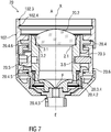
7 schematisch einen justierbaren Faserkollimator sowie -
8 schematisch einen Gewindeadapter.
-
1A schematically the beam path through a focusing beam shaper, -
1B schematically alternating radiance profiles in different image planes of a focusing beam former, -
2 schematically a focused in a housing focusing beam shaper, -
3 schematically the beam path in a beam expander, -
4 schematically a beam expander gripped in a housing, -
5 schematically the beam path in cascaded beam expander, -
6 schematically a captured in a housing fiber collimator -
7 schematically an adjustable fiber collimator as well -
8th schematically a threaded adapter.
Einander entsprechende Teile sind in allen Figuren mit den gleichen Bezugszeichen versehen.Corresponding parts are provided in all figures with the same reference numerals.
Die Phasenplatte
Die fokussierende Linse
Durch Fokussierung des nach dem Airy-Profil verteilten kollimierten Strahlenbündels
Neben dem Top-Hat-Profil entstehen weitere alternierende Strahldichteprofile in Abhängigkeit vom Abstand
In einer ersten, vor dem Brennpunkt
In einem Abstand x=x4>0 nach dem Brennpunkt
Das Gehäuse
Die Feingewinde
In vorteilhafter Weise sind somit in Gehäusen
Das Gehäuse
Somit sind jeweils in Gehäusen
Dabei sind zwei Gehäuse
Die erfindungsgemäße Gestaltung der Gehäuse
In gleicher Weise kann ein Strahldurchmesser an den Durchmesser der im Strahlengang nachgeordneten Linse
Dabei ist es ein Vorteil der Erfindung, dass keine weitere Justierung des fokussierenden Strahlformers
Strahlaufweiter
Bei einer Ausführungsform der Erfindung weisen Strahlaufweiter
Erfindungsgemäß ist der Faserkollimator
In einem Ausführungsbeispiel ist der Faserkollimator
Der justierbare Faserkollimator
Ein justierbarer Faserkollimator
Die Kombination eines solchen justierbaren Faserkollimators
In analoger Weise können die Feingewinde
Der Gewindeadapter
BezugszeichenlisteLIST OF REFERENCE NUMBERS
- 11
- fokussierender Strahlformer, optisches Bauelementfocusing beam shaper, optical component
- 1.11.1
- Phasenplattephase plate
- 1.21.2
- fokussierende Linsefocusing lens
- 22
- Gehäusecasing
- 2.1, 2.32.1, 2.3
- erstes, zweites Feingewindefirst, second fine thread
- 2.2, 2.42.2, 2.4
- erster, zweiter Anschlagfirst, second stop
- 2.2.1, 2.4.12.2.1, 2.4.1
- Anschlagflächestop surface
- 1010
- Strahlaufweiter, optisches BauelementBeam expander, optical component
- 10.1, 10.210.1, 10.2
- erste, zweite optische Flächefirst, second optical surface
- 2020
- Faserkollimator, optisches BauelementFiber collimator, optical component
- 20.220.2
- Sammellinseconverging lens
- 20.320.3
- Fassungversion
- 20.3.420.3.4
- Feingewindefine thread
- 20.420.4
- Faseraufnahmefiber intake
- 20.4.220.4.2
- Feingewindefine thread
- 20.4.320.4.3
- Faserkupplungfiber coupling
- 20.4.520.4.5
- ExzenteraufnahmeExzenteraufnahme
- 20.4.620.4.6
- FixieranschlagFixieranschlag
- 20.520.5
- Fixierschraubefixing screw
- 20.5.220.5.2
- Schraubenkopfscrew head
- 20.620.6
- JustageschaleJustageschale
- 20.6.220.6.2
- längsbewegliche Fixierhalbschalelongitudinally movable fixing half shell
- 20.6.2.220.6.2.2
- Fixierschlitzfixing slot
- 102102
- Kollimatorgehäusecollimator
- 3030
- Gewindeadapterthreaded adapter
- 30.1, 30.330.1, 30.3
- erstes, zweites Feingewindefirst, second fine thread
- 30.2, 30.430.2, 30.4
- erster, zweiter Anschlagfirst, second stop
- 102.3102.3
- austrittsseitiges Feingewindeexit-side fine thread
- 102.4102.4
- austrittsseitiger Anschlagexit-side stop
- xx
- Abstanddistance
- yy
- Profilrichtungprofile direction
- AA
- Austrittexit
- ASAS
- AustrittsstrahlenbündelExit radiation beam
- Ee
- Eintrittentry
- ESIT
- EintrittsstrahlenbündelInput beam
- F F
- Brennpunktfocus
- ff
- Brennweitefocal length
- LL
- Längsachselongitudinal axis
- LSLS
- Längsschnitt der StrahldichteverteilungLongitudinal section of the radiance distribution
- XX
- optische Achseoptical axis
- TP', TP, TP"TP ', TP, TP "
- erstes, zweites, drittes Top-Hat-Profilfirst, second, third top hat profile
- DPDP
- Donut-ProfilDonut profile
- BPBP
- Beam-Waist-ProfilBeam Waist profile
ZITATE ENTHALTEN IN DER BESCHREIBUNG QUOTES INCLUDE IN THE DESCRIPTION
Diese Liste der vom Anmelder aufgeführten Dokumente wurde automatisiert erzeugt und ist ausschließlich zur besseren Information des Lesers aufgenommen. Die Liste ist nicht Bestandteil der deutschen Patent- bzw. Gebrauchsmusteranmeldung. Das DPMA übernimmt keinerlei Haftung für etwaige Fehler oder Auslassungen.This list of the documents listed by the applicant has been generated automatically and is included solely for the better information of the reader. The list is not part of the German patent or utility model application. The DPMA assumes no liability for any errors or omissions.
Zitierte PatentliteraturCited patent literature
- DE 102017205590 [0060]DE 102017205590 [0060]
Claims (9)
Priority Applications (8)
| Application Number | Priority Date | Filing Date | Title |
|---|---|---|---|
| DE102017113945.1A DE102017113945B4 (en) | 2017-06-23 | 2017-06-23 | Modular optical modular system for near-field beam density distributions with alternating beam density profile |
| LTEP18176514.0T LT3418794T (en) | 2017-06-23 | 2018-06-07 | Modular optical modular system for focus-close beam density partitions with alternating beam density profile |
| PL18176514.0T PL3418794T3 (en) | 2017-06-23 | 2018-06-07 | Modular optical modular system for focus-close beam density partitions with alternating beam density profile |
| EP18176514.0A EP3418794B1 (en) | 2017-06-23 | 2018-06-07 | Modular optical modular system for focus-close beam density partitions with alternating beam density profile |
| ES18176514T ES2933506T3 (en) | 2017-06-23 | 2018-06-07 | Modular Optical Modular System for Close Focus Beam Density Partitions with Alternating Beam Density Profile |
| JP2018116754A JP6726703B2 (en) | 2017-06-23 | 2018-06-20 | Optical module system for near-field beam density distribution with alternating beam density profile |
| KR1020180072202A KR102061417B1 (en) | 2017-06-23 | 2018-06-22 | Optical modular system for near-field beam density distributions with alternating beam density profile |
| US16/017,136 US20180372990A1 (en) | 2017-06-23 | 2018-06-25 | Optical modular system for near-field beam density distributions with alternating beam density profile |
Applications Claiming Priority (1)
| Application Number | Priority Date | Filing Date | Title |
|---|---|---|---|
| DE102017113945.1A DE102017113945B4 (en) | 2017-06-23 | 2017-06-23 | Modular optical modular system for near-field beam density distributions with alternating beam density profile |
Publications (2)
| Publication Number | Publication Date |
|---|---|
| DE102017113945A1 true DE102017113945A1 (en) | 2018-12-27 |
| DE102017113945B4 DE102017113945B4 (en) | 2019-11-14 |
Family
ID=62567444
Family Applications (1)
| Application Number | Title | Priority Date | Filing Date |
|---|---|---|---|
| DE102017113945.1A Expired - Fee Related DE102017113945B4 (en) | 2017-06-23 | 2017-06-23 | Modular optical modular system for near-field beam density distributions with alternating beam density profile |
Country Status (8)
| Country | Link |
|---|---|
| US (1) | US20180372990A1 (en) |
| EP (1) | EP3418794B1 (en) |
| JP (1) | JP6726703B2 (en) |
| KR (1) | KR102061417B1 (en) |
| DE (1) | DE102017113945B4 (en) |
| ES (1) | ES2933506T3 (en) |
| LT (1) | LT3418794T (en) |
| PL (1) | PL3418794T3 (en) |
Families Citing this family (1)
| Publication number | Priority date | Publication date | Assignee | Title |
|---|---|---|---|---|
| KR102532094B1 (en) * | 2023-02-21 | 2023-05-12 | 주식회사 브이엘 | Beam expander for testing of secondary battery and semiconductor |
Citations (6)
| Publication number | Priority date | Publication date | Assignee | Title |
|---|---|---|---|---|
| US5864430A (en) * | 1996-09-10 | 1999-01-26 | Sandia Corporation | Gaussian beam profile shaping apparatus, method therefor and evaluation thereof |
| DE102008048323B3 (en) * | 2008-09-22 | 2009-12-17 | Precitec Kg | Modular laser processing system for processing a workpiece comprises a functional module formed as a fiber connection module for holding a fiber end and a functional module formed as a collimator module with a collimator lens |
| DE202010002552U1 (en) * | 2010-02-16 | 2010-06-02 | Smie, Oliver | Interference filter system with extremely small half width |
| DE102012202093A1 (en) * | 2011-02-14 | 2012-08-16 | Hamamatsu Photonics K.K. | Optical system for laser light shaping and wavefront control |
| DE102013206394A1 (en) * | 2013-04-11 | 2014-10-16 | Asphericon Gmbh | Refractive beam shaper |
| DE102017205590B3 (en) | 2017-04-03 | 2017-12-14 | Asphericon Gmbh | Adjustable fiber collimator and method for its assembly |
Family Cites Families (14)
| Publication number | Priority date | Publication date | Assignee | Title |
|---|---|---|---|---|
| US5300756A (en) * | 1991-10-22 | 1994-04-05 | General Scanning, Inc. | Method for severing integrated-circuit connection paths by a phase-plate-adjusted laser beam |
| US5301249A (en) * | 1992-12-31 | 1994-04-05 | Eastman Kodak Company | Catoptric coupling to an optical fiber |
| JPH10282363A (en) * | 1997-04-03 | 1998-10-23 | Nippon Steel Corp | Optical fiber light guide |
| JP4203635B2 (en) * | 1999-10-21 | 2009-01-07 | パナソニック株式会社 | Laser processing apparatus and laser processing method |
| JP2002098930A (en) * | 2000-09-26 | 2002-04-05 | Nec Corp | Laser beam machine |
| JP4201506B2 (en) * | 2002-01-24 | 2008-12-24 | オムロンレーザーフロント株式会社 | Laser processing method and processing machine |
| JP2004252275A (en) * | 2003-02-21 | 2004-09-09 | Sumitomo Electric Ind Ltd | Aspherical Fourier type homogenizer optical system |
| DE202004013136U1 (en) * | 2004-03-11 | 2005-07-21 | Kuka Schweissanlagen Gmbh | Modular optical waveguide lens system esp. for laser optics having a main carrier with a connector and exchangeable lens module |
| JP2009053340A (en) * | 2007-08-24 | 2009-03-12 | Nikon Corp | Objective lens |
| JP2009164034A (en) * | 2008-01-09 | 2009-07-23 | Shimadzu Corp | Laser desorption ionization method, laser desorption ionization apparatus, and mass spectrometer |
| JP2011164182A (en) * | 2010-02-05 | 2011-08-25 | Alps Electric Co Ltd | Optical connector connection body |
| JP2012230366A (en) * | 2011-04-14 | 2012-11-22 | Sumitomo Electric Ind Ltd | Beam homogenizer optical system |
| EP2546019A1 (en) * | 2011-07-11 | 2013-01-16 | Solneva SA | Device and method for structuring solar modules using a laser |
| US9285593B1 (en) * | 2013-12-20 | 2016-03-15 | AdlOptica Optical Systems GmbH | Method and apparatus for shaping focused laser beams |
-
2017
- 2017-06-23 DE DE102017113945.1A patent/DE102017113945B4/en not_active Expired - Fee Related
-
2018
- 2018-06-07 LT LTEP18176514.0T patent/LT3418794T/en unknown
- 2018-06-07 PL PL18176514.0T patent/PL3418794T3/en unknown
- 2018-06-07 ES ES18176514T patent/ES2933506T3/en active Active
- 2018-06-07 EP EP18176514.0A patent/EP3418794B1/en active Active
- 2018-06-20 JP JP2018116754A patent/JP6726703B2/en not_active Expired - Fee Related
- 2018-06-22 KR KR1020180072202A patent/KR102061417B1/en not_active Expired - Fee Related
- 2018-06-25 US US16/017,136 patent/US20180372990A1/en not_active Abandoned
Patent Citations (6)
| Publication number | Priority date | Publication date | Assignee | Title |
|---|---|---|---|---|
| US5864430A (en) * | 1996-09-10 | 1999-01-26 | Sandia Corporation | Gaussian beam profile shaping apparatus, method therefor and evaluation thereof |
| DE102008048323B3 (en) * | 2008-09-22 | 2009-12-17 | Precitec Kg | Modular laser processing system for processing a workpiece comprises a functional module formed as a fiber connection module for holding a fiber end and a functional module formed as a collimator module with a collimator lens |
| DE202010002552U1 (en) * | 2010-02-16 | 2010-06-02 | Smie, Oliver | Interference filter system with extremely small half width |
| DE102012202093A1 (en) * | 2011-02-14 | 2012-08-16 | Hamamatsu Photonics K.K. | Optical system for laser light shaping and wavefront control |
| DE102013206394A1 (en) * | 2013-04-11 | 2014-10-16 | Asphericon Gmbh | Refractive beam shaper |
| DE102017205590B3 (en) | 2017-04-03 | 2017-12-14 | Asphericon Gmbh | Adjustable fiber collimator and method for its assembly |
Also Published As
| Publication number | Publication date |
|---|---|
| DE102017113945B4 (en) | 2019-11-14 |
| LT3418794T (en) | 2022-12-12 |
| KR20190000837A (en) | 2019-01-03 |
| JP6726703B2 (en) | 2020-07-22 |
| US20180372990A1 (en) | 2018-12-27 |
| KR102061417B1 (en) | 2019-12-31 |
| JP2019053277A (en) | 2019-04-04 |
| EP3418794B1 (en) | 2022-10-05 |
| EP3418794A1 (en) | 2018-12-26 |
| PL3418794T3 (en) | 2023-01-23 |
| ES2933506T3 (en) | 2023-02-09 |
Similar Documents
| Publication | Publication Date | Title |
|---|---|---|
| EP1489438B1 (en) | Cylindrical lens array for homogenization of a light beam | |
| DE19948889C1 (en) | Device for balancing the radiation from linear optical emitters and use of the device | |
| WO2012095422A2 (en) | Device for converting the profile of a laser beam into a laser beam with a rotationally symmetrical intensity distribution | |
| DE202007001576U1 (en) | Telescopic sight for firearm has enlarged diameter of outer tube in operating element region and leaf spring to act as restoring force on inner tube | |
| DE102009021251A1 (en) | Device for shaping laser radiation and laser device with such a device | |
| EP2399158B1 (en) | Device for homogenisation of laser radiation | |
| DE102013206394A1 (en) | Refractive beam shaper | |
| DE102013102553A1 (en) | Device for homogenizing laser radiation | |
| EP2469325A2 (en) | Optical system for forming a laser beam and laser system with such an optical system | |
| DE102017113945B4 (en) | Modular optical modular system for near-field beam density distributions with alternating beam density profile | |
| DE102017113947B4 (en) | Modular optical building block system for collimated top hat distribution | |
| DE102012109937A1 (en) | Device for applying light to an inside of a cylinder and beam transformation device for such a device | |
| DE102017116475B4 (en) | Optical modular system with optical free-form surfaces | |
| EP1384105B1 (en) | Beam shaping device for shaping the cross-section of a light beam | |
| WO2015091995A1 (en) | Pump optical unit having an increased number of passages | |
| DE10226280A1 (en) | Beam guidance element has reflective surfaces for generating hollow beam from solid beam (or vice-versa) has odd number of reflective surfaces used for beam deflection | |
| DE10044522C2 (en) | Optical arrangement for beam guidance | |
| DE3210642C1 (en) | Adjustment device for an optical component, e.g. a lens, an optical device | |
| DE102011102588A1 (en) | Optical arrangement for transforming an incident light beam, method for converting a light beam to a line focus and optical device therefor | |
| EP3839609A1 (en) | Laser system for producing a linear laser marking | |
| EP2933671A1 (en) | Robust support structure for an optical mirror telescope | |
| DE102019004352A1 (en) | Fiber collimator with front-side actuatable focusing unit | |
| EP1651994A2 (en) | Arrangement for transforming an optical radiation field | |
| DE102023102056A1 (en) | Fiber-coupled optics for beam shaping | |
| WO2013131709A1 (en) | Projection device |
Legal Events
| Date | Code | Title | Description |
|---|---|---|---|
| R012 | Request for examination validly filed | ||
| R016 | Response to examination communication | ||
| R016 | Response to examination communication | ||
| R018 | Grant decision by examination section/examining division | ||
| R020 | Patent grant now final | ||
| R119 | Application deemed withdrawn, or ip right lapsed, due to non-payment of renewal fee |