DE102017107814B4 - Condition monitoring device for monitoring the condition of a mechanical machine component - Google Patents
Condition monitoring device for monitoring the condition of a mechanical machine component Download PDFInfo
- Publication number
- DE102017107814B4 DE102017107814B4 DE102017107814.2A DE102017107814A DE102017107814B4 DE 102017107814 B4 DE102017107814 B4 DE 102017107814B4 DE 102017107814 A DE102017107814 A DE 102017107814A DE 102017107814 B4 DE102017107814 B4 DE 102017107814B4
- Authority
- DE
- Germany
- Prior art keywords
- monitoring device
- condition monitoring
- designed
- controller
- machine component
- Prior art date
- Legal status (The legal status is an assumption and is not a legal conclusion. Google has not performed a legal analysis and makes no representation as to the accuracy of the status listed.)
- Active
Links
- 238000012806 monitoring device Methods 0.000 title claims abstract description 68
- 238000012544 monitoring process Methods 0.000 title claims abstract description 24
- 238000005259 measurement Methods 0.000 claims abstract description 49
- 238000004891 communication Methods 0.000 claims abstract description 43
- 238000001228 spectrum Methods 0.000 claims description 13
- 230000001360 synchronised effect Effects 0.000 claims description 6
- 230000005540 biological transmission Effects 0.000 claims description 5
- 239000004065 semiconductor Substances 0.000 claims description 5
- 238000001914 filtration Methods 0.000 claims description 3
- 238000005516 engineering process Methods 0.000 abstract description 2
- 230000008901 benefit Effects 0.000 description 18
- 238000000034 method Methods 0.000 description 11
- 238000012545 processing Methods 0.000 description 5
- 238000009529 body temperature measurement Methods 0.000 description 4
- 238000013461 design Methods 0.000 description 4
- 238000011156 evaluation Methods 0.000 description 4
- 238000004590 computer program Methods 0.000 description 3
- 238000012423 maintenance Methods 0.000 description 3
- 230000001419 dependent effect Effects 0.000 description 2
- 238000001514 detection method Methods 0.000 description 2
- 238000003745 diagnosis Methods 0.000 description 2
- 230000002093 peripheral effect Effects 0.000 description 2
- 230000009466 transformation Effects 0.000 description 2
- 230000000712 assembly Effects 0.000 description 1
- 238000000429 assembly Methods 0.000 description 1
- 230000002457 bidirectional effect Effects 0.000 description 1
- 230000008859 change Effects 0.000 description 1
- 230000002950 deficient Effects 0.000 description 1
- 230000010354 integration Effects 0.000 description 1
- 230000007257 malfunction Effects 0.000 description 1
- 230000010358 mechanical oscillation Effects 0.000 description 1
- 230000008520 organization Effects 0.000 description 1
- 230000010355 oscillation Effects 0.000 description 1
- 230000008569 process Effects 0.000 description 1
- 230000035939 shock Effects 0.000 description 1
- 230000008054 signal transmission Effects 0.000 description 1
- 229910052710 silicon Inorganic materials 0.000 description 1
- 239000010703 silicon Substances 0.000 description 1
- 238000012546 transfer Methods 0.000 description 1
Images


Classifications
-
- G—PHYSICS
- G05—CONTROLLING; REGULATING
- G05B—CONTROL OR REGULATING SYSTEMS IN GENERAL; FUNCTIONAL ELEMENTS OF SUCH SYSTEMS; MONITORING OR TESTING ARRANGEMENTS FOR SUCH SYSTEMS OR ELEMENTS
- G05B19/00—Programme-control systems
- G05B19/02—Programme-control systems electric
- G05B19/04—Programme control other than numerical control, i.e. in sequence controllers or logic controllers
- G05B19/042—Programme control other than numerical control, i.e. in sequence controllers or logic controllers using digital processors
- G05B19/0423—Input/output
-
- G—PHYSICS
- G01—MEASURING; TESTING
- G01M—TESTING STATIC OR DYNAMIC BALANCE OF MACHINES OR STRUCTURES; TESTING OF STRUCTURES OR APPARATUS, NOT OTHERWISE PROVIDED FOR
- G01M13/00—Testing of machine parts
- G01M13/04—Bearings
- G01M13/045—Acoustic or vibration analysis
-
- F—MECHANICAL ENGINEERING; LIGHTING; HEATING; WEAPONS; BLASTING
- F16—ENGINEERING ELEMENTS AND UNITS; GENERAL MEASURES FOR PRODUCING AND MAINTAINING EFFECTIVE FUNCTIONING OF MACHINES OR INSTALLATIONS; THERMAL INSULATION IN GENERAL
- F16C—SHAFTS; FLEXIBLE SHAFTS; ELEMENTS OR CRANKSHAFT MECHANISMS; ROTARY BODIES OTHER THAN GEARING ELEMENTS; BEARINGS
- F16C17/00—Sliding-contact bearings for exclusively rotary movement
-
- F—MECHANICAL ENGINEERING; LIGHTING; HEATING; WEAPONS; BLASTING
- F16—ENGINEERING ELEMENTS AND UNITS; GENERAL MEASURES FOR PRODUCING AND MAINTAINING EFFECTIVE FUNCTIONING OF MACHINES OR INSTALLATIONS; THERMAL INSULATION IN GENERAL
- F16C—SHAFTS; FLEXIBLE SHAFTS; ELEMENTS OR CRANKSHAFT MECHANISMS; ROTARY BODIES OTHER THAN GEARING ELEMENTS; BEARINGS
- F16C19/00—Bearings with rolling contact, for exclusively rotary movement
- F16C19/52—Bearings with rolling contact, for exclusively rotary movement with devices affected by abnormal or undesired conditions
- F16C19/527—Bearings with rolling contact, for exclusively rotary movement with devices affected by abnormal or undesired conditions related to vibration and noise
-
- F—MECHANICAL ENGINEERING; LIGHTING; HEATING; WEAPONS; BLASTING
- F16—ENGINEERING ELEMENTS AND UNITS; GENERAL MEASURES FOR PRODUCING AND MAINTAINING EFFECTIVE FUNCTIONING OF MACHINES OR INSTALLATIONS; THERMAL INSULATION IN GENERAL
- F16C—SHAFTS; FLEXIBLE SHAFTS; ELEMENTS OR CRANKSHAFT MECHANISMS; ROTARY BODIES OTHER THAN GEARING ELEMENTS; BEARINGS
- F16C2233/00—Monitoring condition, e.g. temperature, load, vibration
-
- G—PHYSICS
- G05—CONTROLLING; REGULATING
- G05B—CONTROL OR REGULATING SYSTEMS IN GENERAL; FUNCTIONAL ELEMENTS OF SUCH SYSTEMS; MONITORING OR TESTING ARRANGEMENTS FOR SUCH SYSTEMS OR ELEMENTS
- G05B2219/00—Program-control systems
- G05B2219/20—Pc systems
- G05B2219/25—Pc structure of the system
- G05B2219/25428—Field device
-
- G—PHYSICS
- G05—CONTROLLING; REGULATING
- G05B—CONTROL OR REGULATING SYSTEMS IN GENERAL; FUNCTIONAL ELEMENTS OF SUCH SYSTEMS; MONITORING OR TESTING ARRANGEMENTS FOR SUCH SYSTEMS OR ELEMENTS
- G05B2219/00—Program-control systems
- G05B2219/30—Nc systems
- G05B2219/37—Measurements
- G05B2219/37494—Intelligent sensor, data handling incorporated in sensor
Landscapes
- Physics & Mathematics (AREA)
- Engineering & Computer Science (AREA)
- General Physics & Mathematics (AREA)
- General Engineering & Computer Science (AREA)
- Acoustics & Sound (AREA)
- Automation & Control Theory (AREA)
- Mechanical Engineering (AREA)
- Testing Of Devices, Machine Parts, Or Other Structures Thereof (AREA)
- Measurement Of Mechanical Vibrations Or Ultrasonic Waves (AREA)
- Arrangements For Transmission Of Measured Signals (AREA)
- Testing And Monitoring For Control Systems (AREA)
Abstract
Zustandsüberwachungsgerät (100, 200, 300) zum Überwachen des Zustands einer mechanischen Maschinenkomponente, mit:einem Vibrationssensor (110) zur Erfassung von mechanischen Schwingungen an der Maschinenkomponente;einem Controller (101), der mit dem Vibrationssensor (110) gekoppelt ist, und ausgebildet ist, basierend auf von dem Vibrationssensor (110) erzeugten Messdaten (116) einen Zustand der Maschinenkomponente zu bestimmen; undeiner mit dem Controller (101) kommunikationstechnisch gekoppelten, kabelgebundenen Kommunikationsschnittstelle (120) zur Kommunikation mit einem externen Steuergerät,wobei der Controller (101) ausgebildet ist, basierend auf einer Anfrage zur Übermittlung von Informationen über den Zustand der Maschinenkomponente, die angefragten Informationen über die kabelgebundene Kommunikationsschnittstelle (120) zu übertragen,wobei das Zustandsüberwachungsgerät (200, 300) ferner folgendes aufweist:einen ersten Eingang (140) zum Anschluss zumindest eines externen Temperatursensors zur Erfassung zumindest einer Temperatur der Maschinenkomponente, wobei der erste Eingang (140) eine Mehrzahl von RTD-Leitungen zum Anschluss zumindest eines externen Widerstandstemperatursensors umfasst; undeine interne Stromquelle (142), die ausgebildet ist, einen vorgegebenen Strom über die RTD-Leitungen durch den zumindest einen externen Widerstandstemperatursensor zu treiben,wobei der Controller (101) ausgebildet ist, den Zustand der Maschinenkomponente ferner basierend auf Messdaten (146) des ersten Eingangs (140) zu bestimmen.A condition monitoring device (100, 200, 300) for monitoring the condition of a mechanical machine component, comprising: a vibration sensor (110) for detecting mechanical vibrations on the machine component; a controller (101) coupled to the vibration sensor (110), and configured is to determine a state of the machine component based on measurement data (116) generated by the vibration sensor (110); and a wired communication interface (120) coupled in terms of communication technology to the controller (101) for communication with an external control device, wherein the controller (101) is designed, based on a request to transmit information about the state of the machine component, the requested information about the wired communication interface (120), the condition monitoring device (200, 300) also having the following: a first input (140) for connecting at least one external temperature sensor for detecting at least one temperature of the machine component, the first input (140) having a plurality of RTD leads for connecting at least one external resistance temperature sensor; andan internal current source (142) configured to drive a predetermined current through the at least one external resistance temperature sensor via the RTD lines,wherein the controller (101) is configured to determine the state of the machine component further based on measurement data (146) from the first Input (140) to be determined.
Description
Die Erfindung betrifft ein Zustandsüberwachungsgerät zum Überwachen des Zustands einer mechanischen Maschinenkomponente. Insbesondere betrifft die Erfindung ein IO-Link Gerät zum Condition Monitoring.The invention relates to a condition monitoring device for monitoring the condition of a mechanical machine component. In particular, the invention relates to an IO-Link device for condition monitoring.
Beim Condition-Monitoring (CM) geht es um die Zustandsüberwachung von Maschinen und deren mechanischen Baugruppen. Im Wesentlichen soll der Zustand von Lagern überwacht und Lagerschäden frühzeitig erkannt werden, um einen Ausfall der Maschine zu vermeiden. Der Zustand des Lagers lässt sich nach der VDI-Norm 3832 in „keine Schädigung“, „leichte Vorschädigung“ und „Lager defekt“ einteilen.Condition monitoring (CM) is about the condition monitoring of machines and their mechanical assemblies. Essentially, the condition of bearings is to be monitored and damage to bearings is to be detected at an early stage in order to avoid a machine failure. According to VDI standard 3832, the condition of the bearing can be divided into “no damage”, “slight previous damage” and “bearing defective”.
Die Ermittlung des Zustands eines Lagers kann durch eine Vibrationsmessung mit Bewertung der maximal auftretenden Amplitude und des Spektrums der Stoßimpulse erfolgen. Durch die Kombination der Vibrationsmessung mit einer Messung der Lagertemperatur und der Drehzahl lassen sich die Aussagen zum Lagerzustand noch verbessern.The condition of a bearing can be determined by a vibration measurement with evaluation of the maximum occurring amplitude and the spectrum of the shock pulses. By combining the vibration measurement with a measurement of the bearing temperature and the speed, the information on the condition of the bearing can be improved even further.
Derzeit sind nur Feldbusgeräte erhältlich, die über eine der oben genannten Funktionen verfügen. Somit ist jeweils ein Gerät für die Vibrationsmessung, eines für die Temperaturmessung und eines für die Drehzahlmessung erforderlich. Die Feldbusgeräte können nur im Schaltschrank in einer Station und nicht dezentral, z.B. direkt an einer Maschine, betrieben werden. Feldgeräte für die Vibrationsmessung verfügen über den Anschluss eines teuren, externen Piezo-Sensors mit IEPE-Schnittstelle. Die Auswertung aller Signale und somit des Zustands der Maschine erfolgt in einer zentralen, überlagerten Steuerung.Only fieldbus devices are currently available that have one of the functions mentioned above. This means that one device is required for vibration measurement, one for temperature measurement and one for speed measurement. The fieldbus devices can only be operated in the control cabinet in a station and not decentrally, e.g. directly on a machine. Field devices for vibration measurement have the connection of an expensive, external piezo sensor with IEPE interface. The evaluation of all signals and thus the status of the machine takes place in a central, higher-level controller.
Die Druckschrift
Der Wikipedia-Artikel „Point to Point Protocol“ beschreibt das Punkt-zu-Punkt Protokoll.The Wikipedia article "Point to Point Protocol" describes the point-to-point protocol.
Der Wikipedia-Artikel „IO-Link“ beschreibt das IO-Link Protokoll zur Anbindung intelligenter Sensoren und Aktoren an ein Automatisierungssystem.The Wikipedia article "IO-Link" describes the IO-Link protocol for connecting intelligent sensors and actuators to an automation system.
Die Druckschrift SPS-Magazin beschreibt in Ausgabe 10/2013 einen IO-Link-Baustein, der bei Punkt-zu-Punkt-Kommunikation mit IO-Link-Druck-, -Füllstands-, -Temperatur- oder Durchflusssensoren verwendet werden kann (URL: http://www.sps-magazin.de/?inc=artikel/article_show=80815).The publication SPS-Magazin describes in issue 10/2013 an IO-Link module that can be used for point-to-point communication with IO-Link pressure, level, temperature or flow sensors (URL: http://www.sps-magazin.de/?inc=artikel/article_show=80815).
Die Druckschrift
Der Wikipedia-Artikel „Synchron-Serielle Schnittstelle“ beschreibt die Eigenschaften einer synchronen Schnittstelle.The Wikipedia article "Synchronous serial interface" describes the properties of a synchronous interface.
Die Druckschrift
Die Druckschrift
Es ist die Aufgabe der vorliegenden Erfindung, ein Konzept zum verbesserten Condition-Monitoring, insbesondere zur verbesserten Zustandsüberwachung von mechanischen Maschinenkomponenten, zu schaffen.The object of the present invention is to create a concept for improved condition monitoring, in particular for improved condition monitoring of mechanical machine components.
Diese Aufgabe wird durch die Gegenstände mit den Merkmalen nach den unabhängigen Ansprüchen gelöst. Vorteilhafte Ausführungsformen sind Gegenstand der abhängigen Ansprüche, der Beschreibung und der Zeichnungen.This object is achieved by the objects with the features according to the independent claims. Advantageous embodiments are the subject of the dependent claims, the description and the drawings.
Gemäß einem ersten Aspekt wird die Aufgabe gelöst durch ein Zustandsüberwachungsgerät zum Überwachen des Zustands einer mechanischen Maschinenkomponente gemäß Anspruch 1.According to a first aspect, the object is achieved by a state monitoring device for monitoring the state of a mechanical machine component according to claim 1.
Mit einem solchen Zustandsüberwachungsgerät wird der technische Vorteil erreicht, dass sich der Zustand eines Lagers und damit der Zustand der Maschine bzw. Anlage ermitteln lässt. Auf diese Weise lassen sich Verschleiß und Schäden frühzeitig erkennen und die Wartung optimieren.With such a condition monitoring device, the technical advantage is achieved that the condition of a bearing and thus the condition of the machine or system can be determined. In this way, wear and tear and damage can be identified at an early stage and maintenance can be optimized.
In einer vorteilhaften Ausführungsform des Zustandsüberwachungsgeräts ist die Kommunikationsschnittstelle ausgebildet, das Zustandsüberwachungsgerät über eine Punkt-zu-Punkt Verbindung mit dem externen Steuergerät zu koppeln.In an advantageous embodiment of the condition monitoring device, the communication interface is designed to couple the condition monitoring device to the external control device via a point-to-point connection.
Dadurch wird der technische Vorteil erreicht, dass sich das Zustandsüberwachungsgerät einfach und übersichtlich durch das externe Steuergerät bedienen lässt.This has the technical advantage that the condition monitoring device can be operated easily and clearly using the external control device.
In einer vorteilhaften Ausführungsform des Zustandsüberwachungsgeräts ist die Kommunikationsschnittstelle ausgebildet, das Zustandsüberwachungsgerät mit externer Gleichspannung zu versorgen.In an advantageous embodiment of the condition monitoring device, the communication interface is designed to supply the condition monitoring device with external direct voltage.
Dadurch wird der technische Vorteil erreicht, dass das Zustandsüberwachungsgerät kompakt aufgebaut sein kann, da es keine eigene Spannungsversorgung und ein entsprechendes Netzteil bzw. eine Batterie benötigt.This has the technical advantage that the condition monitoring device can have a compact design, since it does not require its own power supply and a corresponding power supply unit or a battery.
In einer vorteilhaften Ausführungsform umfasst das Zustandsüberwachungsgerät einen Gleichspannungswandler, der ausgebildet ist, die über die Kommunikationsschnittstelle zugeführte externe Gleichspannung in eine interne Systemspannung zu wandeln.In an advantageous embodiment, the condition monitoring device comprises a DC voltage converter which is designed to convert the external DC voltage supplied via the communication interface into an internal system voltage.
Dadurch wird der technische Vorteil erreicht, dass die extern zugeführte Versorgungsspannung nicht gleich der internen Systemspannung sein muss. Die bewirkt größere Flexibilität beim Design des Zustandsüberwachungsgeräts.This has the technical advantage that the externally supplied supply voltage does not have to be the same as the internal system voltage. This allows for greater flexibility in the design of the condition monitor.
In einer vorteilhaften Ausführungsform des Zustandsüberwachungsgeräts ist der Controller ausgebildet, als Slave im Master-Slave Betrieb zu operieren und ist über die Kommunikationsschnittstelle steuerbar.In an advantageous embodiment of the condition monitoring device, the controller is designed to operate as a slave in master-slave mode and can be controlled via the communication interface.
Dadurch wird der technische Vorteil erreicht, dass übliche Master-Slave Architekturen eingesetzt werden können. Der Controller kann leistungseffizient aufgebaut sein, da er nur auf Anforderung des Masters arbeiten muss und sich die restliche Zeit im Ruhemodus befinden kann.This has the technical advantage that conventional master-slave architectures can be used. The controller can be designed to be efficient because it only has to work when requested by the master and can be in sleep mode for the rest of the time.
In einer vorteilhaften Ausführungsform des Zustandsüberwachungsgeräts umfasst die Kommunikationsschnittstelle eine IO-Link Schnittstelle.In an advantageous embodiment of the condition monitoring device, the communication interface comprises an IO-Link interface.
Der IO-Link Bus bietet die vorteilhafte Möglichkeit, das Gerät dezentral direkt an die Maschine zu schrauben und über nur ein Kabel die Busverbindung mit Spannungsversorgung herzzustellen.The IO-Link bus offers the advantageous option of screwing the device directly to the machine in a decentralized manner and establishing the bus connection with power supply via just one cable.
In einer vorteilhaften Ausführungsform umfasst das Zustandsüberwachungsgerät einen IO-Link PHY Baustein, der ausgebildet ist, die Informationen über den Zustand der Maschinenkomponente an das externe Steuergerät zu übertragen.In an advantageous embodiment, the status monitoring device comprises an IO-Link PHY module which is designed to transmit the information about the status of the machine component to the external control device.
Dadurch wird der technische Vorteil erreicht, dass das Design des Zustandsüberwachungsgeräts vereinfacht wird, da als IO-Link PHY Baustein ein Standardbaustein eingesetzt werden kann.This has the technical advantage that the design of the condition monitoring device is simplified, since a standard module can be used as the IO-Link PHY module.
Das Zustandsüberwachungsgerät umfasst einen ersten Eingang zum Anschluss zumindest eines externen Temperatursensors zur Erfassung zumindest einer Temperatur der Maschinenkomponente, wobei der Controller ausgebildet ist, den Zustand der Maschinenkomponente ferner basierend auf Messdaten des ersten Eingangs zu bestimmen.The condition monitoring device comprises a first input for connecting at least one external temperature sensor for detecting at least one temperature of the machine component, the controller being designed to further determine the condition of the machine component based on measurement data from the first input.
Durch die Integration des Temperatureingangs wird die Zustandsdiagnose genauer gemacht, da neben dem Vibrationsverhalten auch das Temperaturverhalten der Maschine berücksichtigt wird.The status diagnosis is made more precise by integrating the temperature input, since the temperature behavior of the machine is also taken into account in addition to the vibration behavior.
Der erste Eingang umfasst eine Mehrzahl von RTD-Leitungen zum Anschluss zumindest eines externen Widerstandstemperatursensors.The first input comprises a plurality of RTD lines for connecting at least one external resistance temperature sensor.
Dadurch wird der technische Vorteil erreicht, dass über die RTD-Leitungen eine kompakte Temperaturmessung mit Widerstandstemperatursensoren ermöglicht wird. Das gesamte Zustandsüberwachungsgerät bleibt somit kompakt und kann leicht an der Maschinenkomponente, z.B. einem Lager befestigt werden.This has the technical advantage that compact temperature measurement with resistance temperature sensors is made possible via the RTD lines. The entire condition monitoring device remains compact and can easily be attached to the machine component, e.g. a warehouse.
Das Zustandsüberwachungsgerät umfasst eine interne Stromquelle, die ausgebildet ist, einen vorgegebenen Strom über die RTD-Leitungen durch den zumindest einen externen Widerstandstemperatursensor zu treiben.The condition monitoring device comprises an internal current source which is designed to drive a predetermined current via the RTD lines through the at least one external resistance temperature sensor.
Dadurch wird der technische Vorteil erreicht, dass sich eine effiziente und kompakte Temperaturmessung realisieren lässt, die das Temperaturverhalten eines Widerstands ausnutzt.This has the technical advantage that an efficient and compact temperature measurement can be implemented that uses the temperature behavior of a resistor.
In einer vorteilhaften Ausführungsform umfasst das Zustandsüberwachungsgerät einen ersten Analog-Digital (A/D) Wandler, der ausgebildet ist, einen Spannungsabfall an den RTD-Leitungen zu erfassen und als digitalen Wert gewandelt an den Controller weiterzuleiten.In an advantageous embodiment, the condition monitoring device comprises a first analog-to-digital (A / D) converter which is designed to detect a voltage drop on the RTD lines and to forward it to the controller converted as a digital value.
Dadurch wird der technische Vorteil erreicht, dass der gemessene Spannungsabfall und damit der Temperaturwert sich auf effiziente Weise an den Mikrocontroller übermitteln lässt.This has the technical advantage that the measured voltage drop and thus the temperature value can be transmitted to the microcontroller in an efficient manner.
In einer vorteilhaften Ausführungsform des Zustandsüberwachungsgeräts ist der Controller ausgebildet, basierend auf dem Spannungsabfall an den RTD-Leitungen und dem über die RTD-Leitungen getriebenen vorgegebenen Strom einen zur gemessenen Temperatur des zumindest einen Widerstandstemperatursensors proportionalen Widerstand zu berechnen.In an advantageous embodiment of the condition monitoring device, the controller is designed to calculate a resistance proportional to the measured temperature of the at least one resistance temperature sensor based on the voltage drop on the RTD lines and the predetermined current driven via the RTD lines.
Dadurch wird der technische Vorteil erreicht, dass die Temperaturmessung durch ein paar wenige Operationen sich sehr effizient im Mikrocontroller ausführen lässt, so dass kein komplexer Temperatursensor benötigt wird.This has the technical advantage that the temperature measurement can be performed very efficiently in the microcontroller with just a few operations can be carried out so that no complex temperature sensor is required.
In einer vorteilhaften Ausführungsform umfasst das Zustandsüberwachungsgerät einen zweiten Eingang zum Anschluss zumindest eines externen Drehzahl- und/oder Positionssensors zur Erfassung zumindest einer Drehzahl und/oder Position der Maschinenkomponente, und der Controller ist ausgebildet, den Zustand der Maschinenkomponente ferner basierend auf Messdaten des zweiten Eingangs zu bestimmen.In an advantageous embodiment, the condition monitoring device includes a second input for connecting at least one external speed and / or position sensor for detecting at least one speed and / or position of the machine component, and the controller is designed to further measure the status of the machine component based on measurement data from the second input to determine.
Durch die Integration von Temperatur- und Drehzahlsensoreingängen werden alle nötigen Signale für eine optimale Zustandsdiagnose in einem Gerät vereint. Die Kosten für die Anwendung können ebenfalls gesenkt werden.Through the integration of temperature and speed sensor inputs, all necessary signals for an optimal condition diagnosis are combined in one device. The cost of the application can also be reduced.
In einer vorteilhaften Ausführungsform umfasst das Zustandsüberwachungsgerät zumindest eine synchron-serielle (SSI)-Schnittstelle, die ausgebildet ist, Messdaten des an den zweiten Eingang angeschlossenen zumindest einen externen Drehzahl- und/oder Positionssensors auszulesen und an den Controller zu übertragen.In an advantageous embodiment, the condition monitoring device comprises at least one synchronous serial (SSI) interface which is designed to read out measurement data from the at least one external speed and / or position sensor connected to the second input and to transmit them to the controller.
Dadurch wird der technische Vorteil erreicht, dass sich die Messdaten zur Drehzahl und/oder Position der Maschinenkomponente effizient einlesen lassen und an den Mikrocontroller übertragen werden können.This has the technical advantage that the measurement data on the speed and / or position of the machine component can be efficiently read in and transmitted to the microcontroller.
In einer vorteilhaften Ausführungsform des Zustandsüberwachungsgeräts ist der Vibrationssensor als MEMS-basierter Vibrationssensor auf Halbleiterbasis ausgeführt.In an advantageous embodiment of the condition monitoring device, the vibration sensor is designed as a MEMS-based vibration sensor on a semiconductor basis.
Mit einem MEMS-Sensor, der in das Zustandsüberwachungsgerät integriert ist, besteht nicht mehr die Notwendigkeit, teure externe Piezo-Sensoren zu verwenden, die beispielsweise über eine IEPE-Schnittstelle angekoppelt werden müssen. Mit dem verwendeten MEMS-Sensor lässt sich die Schwingung der Maschinenkomponente, z.B. eines Lagers mit der erforderlichen Bandbreite messen.With a MEMS sensor that is integrated into the condition monitoring device, there is no longer the need to use expensive external piezo sensors that have to be coupled via an IEPE interface, for example. With the MEMS sensor used, the vibration of the machine component, e.g. a bearing, can be measured with the required bandwidth.
In einer vorteilhaften Ausführungsform des Zustandsüberwachungsgeräts ist der Controller ausgebildet, ein Amplitudenspektrum basierend auf den von dem Vibrationssensor erzeugten Messdaten zu ermitteln.In an advantageous embodiment of the condition monitoring device, the controller is designed to determine an amplitude spectrum based on the measurement data generated by the vibration sensor.
Dadurch wird der technische Vorteil erreicht, dass anhand des Amplitudenspektrums sich auf einfache Weise Schwingungen bestimmen lassen, die außerhalb des erlaubten Bereichs der Maschinenkomponente auftreten.This has the technical advantage that vibrations that occur outside of the permitted range of the machine component can be determined in a simple manner on the basis of the amplitude spectrum.
In einer vorteilhaften Ausführungsform umfasst das Zustandsüberwachungsgerät ein Hochpassfilter zum Filtern der von dem Vibrationssensor erzeugten Messdaten; einen Gleichrichter zum Gleichrichten der hochpassgefilterten Messdaten des Vibrationssensors; und einen zweiten Analog-Digital (A/D) Wandler zum Umwandeln der gleichgerichteten hochpassgefilterten Messdaten des Vibrationssensors in digitale Messdaten, wobei der Controller ausgebildet ist, das Amplitudenspektrum basierend auf den digitalen Messdaten des Vibrationssensors zu ermitteln.In an advantageous embodiment, the condition monitoring device comprises a high-pass filter for filtering the measurement data generated by the vibration sensor; a rectifier for rectifying the high-pass filtered measurement data from the vibration sensor; and a second analog-digital (A / D) converter for converting the rectified, high-pass filtered measurement data of the vibration sensor into digital measurement data, the controller being designed to determine the amplitude spectrum based on the digital measurement data of the vibration sensor.
Dadurch wird der technische Vorteil erreicht, dass der abzusuchende Frequenzbereich, in dem ein mögliches Fehlverhalten auftreten kann, sich auf einfache Weise eingrenzen lässt.This has the technical advantage that the frequency range to be searched, in which a possible malfunction can occur, can be narrowed down in a simple manner.
In einer vorteilhaften Ausführungsform des Zustandsüberwachungsgeräts ist der zweite A/D-Wandler im Vibrationssensor integriert, und das Hochpassfilter ist als Funktion im Controller realisiert.In an advantageous embodiment of the condition monitoring device, the second A / D converter is integrated in the vibration sensor, and the high-pass filter is implemented as a function in the controller.
Dadurch wird der technische Vorteil erreicht, dass das Zustandsüberwachungsgerät kompakt ausgeführt sein kann und damit leicht an der Maschinenkomponente angebracht werden kann.This has the technical advantage that the condition monitoring device can be made compact and can therefore be easily attached to the machine component.
In einer vorteilhaften Ausführungsform des Zustandsüberwachungsgeräts umfasst die Kommunikationsschnittstelle einen M12 Schraubenstecker zur Anschaltung des externen Steuergeräts und zur Spannungsversorgung.In an advantageous embodiment of the condition monitoring device, the communication interface comprises an M12 screw plug for connecting the external control device and for the voltage supply.
Dadurch wird der technische Vorteil erreicht, dass eine kompakte und robuste Verbindung erzielt werden kann, die sich im Betriebsmodus der Maschinenkomponente nicht lockert, so dass zuverlässige Überwachungsergebnisse erzielt werden.This has the technical advantage that a compact and robust connection can be achieved which does not loosen in the operating mode of the machine component, so that reliable monitoring results are achieved.
Gemäß einem zweiten Aspekt wird die Aufgabe gelöst durch ein Verfahren zum Überwachen des Zustands einer mechanischen Maschinenkomponente, wobei das Verfahren die folgenden Schritte aufweist: Erfassung von mechanischen Schwingungen an einer Maschinenkomponente durch einen Vibrationssensor; Bestimmen eines Zustand der Maschinenkomponente basierend auf von dem Vibrationssensor erzeugten Messdaten; und Übertragen von Informationen über den Zustand der Maschinenkomponente über eine kabelgebundene Kommunikationsschnittstelle basierend auf einer Anfrage zur Übermittlung der Informationen.According to a second aspect, the object is achieved by a method for monitoring the state of a mechanical machine component, the method comprising the following steps: detection of mechanical vibrations on a machine component by a vibration sensor; Determining a state of the machine component based on measurement data generated by the vibration sensor; and transmitting information about the state of the machine component via a wired communication interface based on a request for transmitting the information.
Mit einem solchen Verfahren wird der technische Vorteil erreicht, dass sich der Zustand eines Lagers und damit der Zustand der Maschine bzw. Anlage ermitteln lässt. Auf diese Weise lassen sich Verschleiß und Schäden frühzeitig erkennen und die Wartung optimieren.With such a method, the technical advantage is achieved that the condition of a bearing and thus the condition of the machine or system can be determined. In this way, wear and tear and damage can be identified at an early stage and maintenance can be optimized.
Ferner wird der technische Vorteil erreicht, dass das Verfahren einfach in einem Automatisierungssystem eingesetzt werden kann.Furthermore, the technical advantage is achieved that the method can easily be used in an automation system.
Gemäß einem dritten Aspekt wird die Aufgabe gelöst durch ein Computerprogramm mit einem Programmcode zum Ausführen eines derartigen Verfahrens, wenn der Programmcode auf einem Computer ausgeführt wird.According to a third aspect, the object is achieved by a computer program with a program code for executing such a method when the program code is executed on a computer.
Mit einem solchen Computerprogramm wird der technische Vorteil erreicht, dass sich der Zustand eines Lagers und damit der Zustand der Maschine bzw. Anlage ermitteln lässt. Auf diese Weise lassen sich Verschleiß und Schäden frühzeitig erkennen und die Wartung optimieren. Das Computerprogramm lässt sich leicht auf einem Zustandsüberwachungsgerät gemäß dieser Offenbarung realisieren.With such a computer program the technical advantage is achieved that the condition of a bearing and thus the condition of the machine or system can be determined. In this way, wear and tear and damage can be identified at an early stage and maintenance can be optimized. The computer program can easily be implemented on a condition monitoring device according to this disclosure.
Weitere Ausführungsbeispiele werden Bezug nehmend auf die beiliegenden Zeichnungen erläutert. Es zeigen:
-
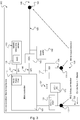
1 eine schematische Darstellung eines Zustandsüberwachungsgeräts 100 zum Überwachen des Zustands einer mechanischen Maschinenkomponente, -
2 eine schematische Darstellung eines IO-Link Geräts 200 zum Condition Monitoring gemäß einer ersten Ausführungsform, -
3 eine schematische Darstellung eines IO-Link Geräts 300 zum Condition Monitoring gemäß einer zweiten Ausführungsform, und -
4 eine schematische Darstellung eines Verfahrens 400 zum Überwachen des Zustands einer mechanischen Maschinenkomponente.
-
1 a schematic representation of acondition monitoring device 100 for monitoring the condition of a mechanical machine component, -
2 a schematic representation of an IO-Link device 200 for condition monitoring according to a first embodiment, -
3 a schematic representation of an IO-Link device 300 for condition monitoring according to a second embodiment, and -
4th a schematic representation of amethod 400 for monitoring the condition of a mechanical machine component.
Im Folgenden werden IO-Link Systeme und IO-Link Geräte bzw. Messgeräte mit IO-Link Schnittstelle beschrieben.IO-Link systems and IO-Link devices or measuring devices with IO-Link interface are described below.
Bei IO-Link handelt es sich um eine serielle, bidirektionale Punkt-zu-Punkt-Verbindung für Signalübertragung und Energieversorgung unterhalb beliebiger Netzwerke, Feldbusse bzw. Rückwandbusse.IO-Link is a serial, bidirectional point-to-point connection for signal transmission and energy supply under any network, fieldbus or backplane bus.
Ein IO-Link System besteht aus IO-Link Geräten, meist Sensoren, Aktoren oder Kombinationen hieraus sowie einem Standard 3-Leiter Sensor- / Aktorkabel und einem IO-Link Master. Dabei kann der Master als Gerät beliebiger Bauweise und Schutzart ausgeführt werden.An IO-Link system consists of IO-Link devices, mostly sensors, actuators or combinations thereof as well as a standard 3-wire sensor / actuator cable and an IO-Link master. The master can be designed as a device of any design and degree of protection.
Der IO-Link Master stellt die Verbindung zwischen den IO-Link Devices bzw. IO-Link Geräten und dem Automatisierungssystem her. Als Bestandteil eines Peripheriesystems ist der IO-Link Master beispielsweise entweder im Schaltschrank oder als Remote-I/O direkt im Feld installiert. Der IO-Link Master kommuniziert über verschiedene Feldbusse oder produktspezifische Rückwandbusse. Ein IO-Link Master kann mehrere IO-Link Ports (Kanäle) besitzen. An jedem Port ist ein IO-Link Device anschließbar (über Punkt-zu-Punkt-Kommunikation). Somit ist IO-Link eine Punkt-zu-Punkt-Kommunikation.The IO-Link master establishes the connection between the IO-Link devices or IO-Link devices and the automation system. As part of a peripheral system, the IO-Link master is installed either in the control cabinet or as a remote I / O directly in the field. The IO-Link master communicates via various field buses or product-specific backplane buses. An IO-Link master can have several IO-Link ports (channels). An IO-Link device can be connected to each port (via point-to-point communication). This means that IO-Link is point-to-point communication.
Für die Anschlusstechnik in IP65/67 sind unter anderem M12-Steckverbinder definiert, wobei Sensoren üblicherweise einen 4-poligen Stecker und Aktoren einen 5-poligen Stecker haben. IO-Link Master verfügen grundsätzlich über eine 5-polige M12-Buchse.For connection technology in IP65 / 67, M12 connectors are defined, among other things, whereby sensors usually have a 4-pin connector and actuators a 5-pin connector. IO-Link masters always have a 5-pin M12 socket.
Die Anschlussbelegung ist laut IEC 60974-5-2 wie folgt spezifiziert: Pin 1: 24 V; Pin 3: 0 V; Pin 4: Schalt- und Kommunikationsleitung (C/Q). Über diese 3 Pins wird neben der IO-Link Kommunikation auch eine Energieversorgung des Geräts mit maximal 200 mA realisiert. The pin assignment is specified as follows according to IEC 60974-5-2: Pin 1: 24 V; Pin 3: 0 V; Pin 4: Switching and communication line (C / Q). In addition to IO-Link communication, these 3 pins also provide a power supply for the device with a maximum of 200 mA.
Im Folgenden werden Messgeräte mit SPI und UART Schnittstelle beschrieben. Das Serial Peripheral Interface (kurz SPI) ist ein Bus-System für einen synchronen seriellen Datenbus, mit dem digitale Schaltungen nach dem Master-Slave-Prinzip miteinander verbunden werden können. Eine UART-Schnittstelle dient zum Senden und Empfangen von Daten über eine Datenleitung und bildet den Standard der seriellen Schnittstellen an PCs, Mikrocontrollern sowie im industriellen Bereich. Die Daten werden als serieller digitaler Datenstrom mit einem fixen Rahmen übertragen, der aus einem Start-Bit, fünf bis maximal neun Datenbits, einem optionalen Parity-Bit zur Erkennung von Übertragungsfehlern und einem Stopp-Bit besteht.In the following, measuring devices with SPI and UART interfaces are described. The Serial Peripheral Interface (SPI for short) is a bus system for a synchronous serial data bus with which digital circuits can be connected to one another according to the master-slave principle. A UART interface is used to send and receive data via a data line and forms the standard for serial interfaces on PCs, microcontrollers and in the industrial sector. The data is transmitted as a serial digital data stream with a fixed frame consisting of a start bit, five to a maximum of nine data bits, an optional parity bit to detect transmission errors and a stop bit.
Die im Folgenden beschriebenen Geräte umfassen Kommunikationsschnittstellen, die nach dem Master-Slave Prinzip arbeiten. Master-Slave bzw. Hauptrechner-Satellitenrechner, ist ein hierarchisches Konzept für die Organisation und Verteilung von Aufgaben zwischen übergeordneten Stationen - hier die Master-Stationen - und untergeordneten Recheneinheiten, den Slaves. Solche Konzepte werden immer dann eingesetzt, wenn eine Recheneinheit die Steuerung und Aufgabenverteilung von einer anderen übernimmt.The devices described below include communication interfaces that work on the master-slave principle. Master-slave or main computer satellite computer is a hierarchical concept for the organization and distribution of tasks between higher-level stations - here the master stations - and subordinate processing units, the slaves. Such concepts are always used when one processing unit takes over control and task distribution from another.
Das Master-Slave-Konzept wird unter anderem in Client-Server Architekturen, Feldbussen und Bluetooth realisiert. Beim Client-Server-Prinzip arbeitet der Server als Master-Station, die mit einem eigenen Betriebssystem, höherer Intelligenz und einem höheren Funktionsumfang ausgestattet ist als die Clients. Die als Slave-Stationen fungierenden Clients sind passive Kommunikationsteilnehmer, die durch die Master-Station aufgefordert werden Daten zu empfangen oder zu senden.The master-slave concept is implemented in client-server architectures, field buses and Bluetooth, among other things. In the client-server principle, the server works as a master station, which is equipped with its own operating system, higher intelligence and a greater range of functions than the clients. The clients acting as slave stations are passive communication participants who are requested by the master station to receive or send data.
Im Folgenden werden MEMS-Sensoren, insbesondere MEMS-Vibrationssensoren beschrieben. MEMS (Micro-Electro-Mechanical Systems) sind winzige Bauelemente, die Logikelemente und mikromechanische Strukturen in einem Chip vereinen. Sie können mechanische und elektrische Informationen verarbeiten. MEMS Elemente werden in Sensoren, Aktoren, Oszillatoren und Filtern eingesetzt. Diese Mechatronik-Chips werden meist aus Silizium hergestellt. Die Strukturen können kleiner als ein Mikrometer sein. Aufgrund der Miniaturisierung lassen sie sich wie Halbleiter billig und in Massen fertigen. MEMS-Vibrationssensoren sind dafür ausgelegt, Vibrationen bzw. mechanische Schwingungen zu messen.MEMS sensors, in particular MEMS vibration sensors, are described below. MEMS (Micro-Electro-Mechanical Systems) are tiny components that combine logic elements and micromechanical structures in one chip. They can process mechanical and electrical information. MEMS elements are used in sensors, actuators, oscillators and filters. These mechatronic chips are mostly made of silicon. The structures can be smaller than a micrometer. As a result of miniaturization, like semiconductors, they can be manufactured cheaply and in large quantities. MEMS vibration sensors are designed to measure vibrations or mechanical oscillations.
Der Vibrationssensor 110 dient der Erfassung von mechanischen Schwingungen an der Maschinenkomponente. Der Controller 101 ist mit dem Vibrationssensor 110 gekoppelt und ausgebildet, basierend auf von dem Vibrationssensor 110 erzeugten Messdaten 116 einen Zustand der Maschinenkomponente zu bestimmen. Die Kommunikationsschnittstelle 120 ist mit dem Controller 101 kommunikationstechnisch gekoppelt und dafür ausgelegt, mit einem externen Steuergerät zu kommunizieren. Der Controller 101 ist ausgebildet, basierend auf einer Anfrage zur Übermittlung von Informationen über den Zustand der Maschinenkomponente, die angefragten Informationen über die kabelgebundene Kommunikationsschnittstelle 120 zu übertragen.The
Die Kommunikationsschnittstelle 120 kann beispielsweise ausgebildet sein, das Zustandsüberwachungsgerät 100 über eine Punkt-zu-Punkt Verbindung mit dem externen Steuergerät zu koppeln. Die Kommunikationsschnittstelle 120 kann ausgebildet sein, das Zustandsüberwachungsgerät mit externer Gleichspannung zu versorgen.The
Der Controller 101 kann als Slave im Master-Slave Betrieb operieren und kann über die Kommunikationsschnittstelle 120 gesteuert werden.The
Die Kommunikationsschnittstelle 120 kann eine IO-Link Schnittstelle umfassen, wie beispielsweise in den
Das Zustandsüberwachungsgerät 100 kann einen IO-Link PHY Baustein 121, wie beispielsweise in den
In einer Ausführungsform umfasst das Zustandsüberwachungsgerät 100 einen Gleichspannungswandler 123, der ausgebildet ist, die über die Kommunikationsschnittstelle 120 zugeführte externe Gleichspannung in eine interne Systemspannung 124 zu wandeln, beispielsweise gemäß der Darstellung in
In einer Ausführungsform kann das Zustandsüberwachungsgerät 100 einen ersten Eingang 140 zum Anschluss zumindest eines externen Temperatursensors zur Erfassung zumindest einer Temperatur der Maschinenkomponente umfassen, wie beispielsweise in den
Der erste Eingang 140 kann eine Mehrzahl von RTD-Leitungen zum Anschluss zumindest eines externen Widerstandstemperatursensors umfassen. Das Zustandsüberwachungsgerät 100 kann ferner eine interne Stromquelle 142 aufweisen, wie beispielsweise in den
Das Zustandsüberwachungsgerät 100 kann ferner einen zweiten Eingang 130 zum Anschluss zumindest eines externen Drehzahl- und/oder Positionssensors zur Erfassung zumindest einer Drehzahl und/oder Position der Maschinenkomponente umfassen, wie beispielsweise in den
Der Vibrationssensor 110 kann beispielsweise als MEMS-basierter Vibrationssensor auf Halbleiterbasis ausgeführt sein.The
Der Controller 101 kann ausgebildet sein, ein Amplitudenspektrum basierend auf den von dem Vibrationssensor 110 erzeugten Messdaten 116 zu ermitteln, beispielsweise anhand einer Frequenztransformation wie einer DFT oder FFT.The
In einer Ausführungsform kann das Zustandsüberwachungsgerät 100 ein Hochpassfilter 111 zum Filtern der von dem Vibrationssensor 110 erzeugten Messdaten 116 aufweisen, sowie einen Gleichrichter 112 zum Gleichrichten der hochpassgefilterten Messdaten des Vibrationssensors 110; und einen zweiten Analog-Digital (A/D) Wandler 113 zum Umwandeln der gleichgerichteten hochpassgefilterten Messdaten des Vibrationssensors 110 in digitale Messdaten, wie beispielsweise in den
In einer Ausführungsform kann der zweite A/D-Wandler 113 im Vibrationssensor 110 integriert sein, wie beispielsweise in
In einer Ausführungsform kann die Kommunikationsschnittstelle 120 einen M12 Schraubenstecker 122 zur Anschaltung des externen Steuergeräts und zur Spannungsversorgung umfassen, wie beispielsweise in den
Das IO-Link Gerät 200 bildet eine spezielle Ausführungsform des oben zu
Der Vibrationssensor 110 dient der Erfassung von mechanischen Schwingungen an der Maschinenkomponente. Der Controller 101 ist mit dem Vibrationssensor 110 gekoppelt und ausgebildet, basierend auf von dem Vibrationssensor 110 erzeugten Messdaten 116 einen Zustand der Maschinenkomponente zu bestimmen. Die IO-Link Schnittstelle 120 ist mit dem Controller 101 kommunikationstechnisch gekoppelt und dafür ausgelegt, mit einem externen Steuergerät, beispielsweise einem IO-Link Master, zu kommunizieren. Der Controller 101 ist ausgebildet, basierend auf einer Anfrage des externen Steuergeräts zur Übermittlung von Informationen über den Zustand der Maschinenkomponente, die angefragten Informationen über die kabelgebundene Kommunikationsschnittstelle 120 an das externe Steuergerät zu übertragen.The
Das IO-Link Gerät 200 umfasst ein IO-Link PHY Modul, das die Kommunikation zum IO-Link Master auf physikalischer Ebene realisiert und die Daten von dem als Slave fungierenden IO-Link Gerät 200 an das als Master fungierende Steuergerät übermittelt. Die Kommunikationsschnittstelle umfasst einen M12 Schraubenstecker 122, an den ein Kabel geschraubt werden kann, um das IO-Link Gerät 200 mit dem Steuergerät zu verbinden. Über den IO-Link 120 wird die Versorgungsspannung des IO-Link Geräts 200 übertragen, welche in einer DC/DC Komponente in die Systemspannung des IO-Link Geräts 200, z.B. 3.3 V gewandelt werden kann.The IO-
Der Vibrationssensor 110 ist als MEMS Vibrationssensor ausgeführt und über ein Hochpassfilter 111, einen Gleichrichter 112 und einen Analog-Digital Wandler 113 an eine SPI Schnittstelle des Mikrocontrollers 101 gekoppelt.The
Ein erster Eingang 140 dient der Ankopplung eines oder mehrerer Temperatursensoren, z.B. Widerstandsthermometer, über einen M8 Schraubstecker 141. Eine Stromquelle 142 liefert einen vordefinierten Strom, um den oder die Temperatursensoren mit Strom zu treiben. Die dadurch bewirkte temperaturabhängige Spannungsänderung wird von einem zweiten Analog-Digital Wandler 143 aufgezeichnet und in einen digitalen Messwert gewandelt, der an eine SPI Schnittstelle 144 des Mikrocontrollers 101 übertragen wird.A
Ein zweiter Eingang 130 dient der Ankopplung eines oder mehrerer Drehzahl und/oder Positionssensoren über einen M8 Schraubstecker 131. Die Messwerte 136 dieser Sensoren werden von einer SSI Schnittstelle 132 ausgelesen und dem Mikroprozessor zur Verfügung gestellt.A
Bei dem in
Das Gerät 200 ist als IO-Link Slave (Device) ausgeführt und wird über den standardisierten M12 Schraubstecker 122 an den IO-Link Master angeschlossen. In der IO-Link-Leitung 120 wird neben den Bussignalen auch eine 24V Betriebsspannung mitgeführt, mit der das Gerät 200 versorgt wird. Mit einem integrierten DC/DC Wandler 123 werden im Gerät 200 aus den 24V die 3.3 V Systemspannung 124 erzeugt. Über den IO-Link Phy 121 werden die Daten vom Slave 200 an den Master übermittelt.The
Das Gerät 200 verfügt über einen integrierten MEMS-basierten (auf Halbleiterbasis) Vibrationssensor 110. Die analogen Sensorsignale 116 werden für eine optimale Auswertung des Spektrums und der Amplitude der Schwingung zunächst diskret hochpassgefiltert 111, gleichgerichtet 112 und mit einem Analog/Digital-Wandler 113 erfasst. Die Übertragung der Messwerte vom ADC 113 an den Mikrocontroller 101 erfolgt über ein SPI-Interface 114.The
Alternativ kann der ADC 113 im Vibrationssensor 110 integriert sein, wie in der zweiten Ausführungsform des IO-Link Geräts 300 in
An die zwei oder mehr RTD-Temperatureingänge 140 lassen sich mit M8 Schraubsteckern 141, z.B. PT100 Temperatursensoren anschließen. Der elektrische Widerstand des Sensors ist proportional zur Temperatur. Interne Stromquellen 142 treiben einen definierten Strom durch den Temperatursensor. Der mit einem Analog/Digital-Wandler 143 gemessene Spannungsabfall am Sensor wird über ein SPI-Interface 144 an den Mikrocontroller 101 übertragen. Im Mikrocontroller 101 wird mittels des Spannungsabfalls und des getriebenen Stroms der zur Temperatur proportionale Widerstand berechnet.M8 screw plugs 141, e.g. PT100 temperature sensors, can be connected to the two or more
An die eine oder mehreren SSI-Schnittstellen 132 lassen sich Drehzahl- oder Positionssensoren anschließen. Die Daten werden vom Sensor über den Hardware-Treiber an den Mikrocontroller 101 übertragen und von diesem ausgewertet.Rotational speed or position sensors can be connected to the one or more SSI interfaces 132. The data are transmitted from the sensor via the hardware driver to the
Der Mikrocontroller 101 erfasst die einzelnen Sensorsignale und berechnet daraus die Lagertemperatur, die Drehzahl, die Amplitude und Spektrum der Schwingung sowie den Zustand des Lagers. Der Mikrocontroller 101 ist über ein UART-Interface mit dem IO-Link PHY 121 verbunden, beinhaltet den IO-Link Stack und stellt die Kommunikation zum Master zur Datenübertragung her.The
Das IO-Link Gerät 300 bildet eine spezielle Ausführungsform des oben zu
Das Verfahren 400 umfasst die folgenden Schritte: Erfassung 401 von mechanischen Schwingungen an einer Maschinenkomponente durch einen Vibrationssensor; Bestimmen 402 eines Zustand der Maschinenkomponente basierend auf von dem Vibrationssensor erzeugten Messdaten; und Übertragen 403 von Informationen über den Zustand der Maschinenkomponente über eine kabelgebundene Kommunikationsschnittstelle basierend auf einer Anfrage zur Übermittlung der Informationen.The
Das Verfahren 400 kann beispielsweise in einem Zustandsüberwachungsgerät 100 oder einem IO-Link Gerät 200, 300, wie oben zu den
BezugszeichenlisteList of reference symbols
- 100100
- ZustandsüberwachungsgerätCondition monitoring device
- 101101
- Controller, MicrocontrollerController, microcontroller
- 110110
- Vibrationssensor, MEMS-VibrationssensorVibration sensor, MEMS vibration sensor
- 111111
- HochpassfilterHigh pass filter
- 112112
- GleichrichterRectifier
- 113113
- Analog-Digital WandlerAnalog-to-digital converter
- 114114
- SPI InterfaceSPI interface
- 116116
- Messdaten des VibrationssensorsMeasurement data of the vibration sensor
- 120120
- Kommunikationsschnittstelle, kabelgebunden, IO-Link Bus zum MasterCommunication interface, wired, IO-Link bus to the master
- 121121
- IO-Link PHYIO-Link PHY
- 122122
- M12 SchraubensteckerM12 screw connector
- 130130
- zweiter Eingangsecond entrance
- 131131
- M8 SchraubensteckerM8 screw connector
- 132132
- SSI SchnittstelleSSI interface
- 136136
- Messdaten des zweiten EingangsMeasurement data of the second input
- 140140
- erster Eingangfirst entrance
- 141141
- M8 SchraubensteckerM8 screw connector
- 142142
- StromquellePower source
- 143143
- Analog-Digital WandlerAnalog-to-digital converter
- 144144
- SPI SchnittstelleSPI interface
- 146146
- Messdaten des ersten Eingangs Measurement data of the first input
- 200200
- IO-Link Gerät gemäß erster AusführungsformIO-Link device according to the first embodiment
- 300300
- IO-Link Gerät gemäß zweiter Ausführungsform IO-Link device according to the second embodiment
- 400400
- Verfahren zum Überwachen des Zustands einer mechanischen MaschinenkomponenteMethod for monitoring the condition of a mechanical machine component
- 401401
- erste Schritt: Erfassenfirst step: capture
- 402402
- zweiter Schritt: Bestimmensecond step: determine
- 403403
- dritter Schritt: Übertragenthird step: transfer
Claims (16)
Priority Applications (5)
| Application Number | Priority Date | Filing Date | Title |
|---|---|---|---|
| DE102017107814.2A DE102017107814B4 (en) | 2017-04-11 | 2017-04-11 | Condition monitoring device for monitoring the condition of a mechanical machine component |
| CN201880024384.7A CN110537150A (en) | 2017-04-11 | 2018-04-06 | Condition monitoring equipment for monitoring the condition of mechanical machine parts |
| PCT/EP2018/000166 WO2018188780A1 (en) | 2017-04-11 | 2018-04-06 | State monitoring device for monitoring the state of a mechanical machine component |
| EP18716890.1A EP3610338B1 (en) | 2017-04-11 | 2018-04-06 | State monitoring device for monitoring the state of a mechanical machine component |
| US16/603,917 US12241806B2 (en) | 2017-04-11 | 2018-04-06 | Condition monitoring device for monitoring the condition of a mechanical machine component |
Applications Claiming Priority (1)
| Application Number | Priority Date | Filing Date | Title |
|---|---|---|---|
| DE102017107814.2A DE102017107814B4 (en) | 2017-04-11 | 2017-04-11 | Condition monitoring device for monitoring the condition of a mechanical machine component |
Publications (2)
| Publication Number | Publication Date |
|---|---|
| DE102017107814A1 DE102017107814A1 (en) | 2018-10-11 |
| DE102017107814B4 true DE102017107814B4 (en) | 2022-01-05 |
Family
ID=61952614
Family Applications (1)
| Application Number | Title | Priority Date | Filing Date |
|---|---|---|---|
| DE102017107814.2A Active DE102017107814B4 (en) | 2017-04-11 | 2017-04-11 | Condition monitoring device for monitoring the condition of a mechanical machine component |
Country Status (5)
| Country | Link |
|---|---|
| US (1) | US12241806B2 (en) |
| EP (1) | EP3610338B1 (en) |
| CN (1) | CN110537150A (en) |
| DE (1) | DE102017107814B4 (en) |
| WO (1) | WO2018188780A1 (en) |
Families Citing this family (7)
| Publication number | Priority date | Publication date | Assignee | Title |
|---|---|---|---|---|
| ES2971734T3 (en) * | 2017-12-29 | 2024-06-06 | Datalogic IP Tech Srl | IO-Link device |
| CN110400451A (en) * | 2019-08-06 | 2019-11-01 | 江苏金恒信息科技股份有限公司 | Vibration measuring temp measuring system based on LoRa wireless communication |
| DE102019216492A1 (en) * | 2019-10-25 | 2021-04-29 | Robert Bosch Gmbh | Method for monitoring the function of an assembly in the motor vehicle by means of a MEMS sensor, as well as an electric drive unit for carrying out the method |
| DE102021108770A1 (en) * | 2021-04-08 | 2022-10-13 | Balluff Gmbh | IO-Link system with diagnostics channel |
| CN116386245A (en) * | 2023-06-07 | 2023-07-04 | 吉林省日月智感互联科技有限公司 | Unmanned on duty alarm system and method based on modularized design |
| DE102023116914A1 (en) * | 2023-06-27 | 2025-01-02 | Turck Holding Gmbh | Device for connecting a field device to a control system |
| CN119420455B (en) * | 2024-11-01 | 2025-11-21 | 杭州电力设备制造有限公司 | Communication system and method |
Citations (4)
| Publication number | Priority date | Publication date | Assignee | Title |
|---|---|---|---|---|
| US6789030B1 (en) | 2000-06-23 | 2004-09-07 | Bently Nevada, Llc | Portable data collector and analyzer: apparatus and method |
| US7093492B2 (en) | 2004-03-19 | 2006-08-22 | Mechworks Systems Inc. | Configurable vibration sensor |
| WO2015002617A1 (en) | 2013-07-01 | 2015-01-08 | Jirapong Lim | Multi-function machine condition analyzer instrument |
| US20150168268A1 (en) | 2013-12-16 | 2015-06-18 | Tdg Aerospace, Inc. | Monitoring systems and methods |
Family Cites Families (29)
| Publication number | Priority date | Publication date | Assignee | Title |
|---|---|---|---|---|
| US6148258A (en) | 1991-10-31 | 2000-11-14 | Nartron Corporation | Electrical starting system for diesel engines |
| SE510771C2 (en) | 1996-07-05 | 1999-06-21 | Spm Instr Ab | Procedure for evaluating the condition of a machine as well as the analyzer and apparatus for cooperation with the analyzer |
| US5852793A (en) | 1997-02-18 | 1998-12-22 | Dme Corporation | Method and apparatus for predictive diagnosis of moving machine parts |
| US6199018B1 (en) * | 1998-03-04 | 2001-03-06 | Emerson Electric Co. | Distributed diagnostic system |
| US20030025612A1 (en) * | 1999-08-16 | 2003-02-06 | Holmes John K. | Wireless end device |
| US7034711B2 (en) | 2001-08-07 | 2006-04-25 | Nsk Ltd. | Wireless sensor, rolling bearing with sensor, management apparatus and monitoring system |
| EP1502086A2 (en) | 2002-04-13 | 2005-02-02 | I-For-T Gmbh | Vibration sensor and method for monitoring the condition of rotating components and bearings |
| US6839660B2 (en) * | 2002-04-22 | 2005-01-04 | Csi Technology, Inc. | On-line rotating equipment monitoring device |
| DE10238529A1 (en) * | 2002-08-22 | 2004-03-04 | Robert Bosch Gmbh | control unit |
| DE10305986B4 (en) * | 2003-02-12 | 2022-07-21 | IAD Gesellschaft für Informatik, Automatisierung und Datenverarbeitung mbH | Measuring system with intelligent sensor head for medium or high voltage systems or in mining |
| CN1878038A (en) * | 2005-06-07 | 2006-12-13 | 洛克威尔自动控制技术股份有限公司 | Wireless modular monitoring and protection system topology |
| WO2007147617A1 (en) * | 2006-06-23 | 2007-12-27 | Ab Skf | Vibration and condition monitoring system and the parts thereof |
| US7424403B2 (en) | 2006-09-29 | 2008-09-09 | Csi Technology, Inc. | Low power vibration sensor and wireless transmitter system |
| US9483429B2 (en) * | 2008-07-14 | 2016-11-01 | Texas Instruments Incorporated | Unified input/output controller for integrated wireless devices |
| CN102792240B (en) * | 2009-11-16 | 2016-06-01 | Nrg系统股份有限公司 | Data acquisition system for condition-based maintenance |
| US9133727B2 (en) * | 2010-01-12 | 2015-09-15 | Advanced F.M.E. Products | Sensor foreign material exclusion devices and methods |
| SE535559C2 (en) | 2010-01-18 | 2012-09-25 | Spm Instr Ab | Method and apparatus for analyzing the condition of rotating part machine |
| EP3527961A1 (en) * | 2011-07-14 | 2019-08-21 | S.P.M. Instrument AB | A condition monitoring system |
| US20130030765A1 (en) | 2011-07-27 | 2013-01-31 | Danni David | System and method for use in monitoring machines |
| BR112014026505A2 (en) * | 2012-04-24 | 2017-06-27 | Skf Ab | bearing monitoring method and system |
| DE102012109393A1 (en) | 2012-10-02 | 2014-04-03 | Prüftechnik Dieter Busch AG | Apparatus and method for evaluating vibrations |
| US9946680B2 (en) * | 2012-10-05 | 2018-04-17 | Analog Devices, Inc. | Peripheral device diagnostics and control over a two-wire communication bus |
| DE102012109583A1 (en) * | 2012-10-09 | 2014-04-10 | Prüftechnik Dieter Busch AG | Sensor arrangement and method for generating an output signal |
| US8924600B2 (en) * | 2013-03-14 | 2014-12-30 | General Electric Company | Programmable universal IO interface |
| US9237039B2 (en) * | 2013-06-27 | 2016-01-12 | Stmicroelectronics S.R.L. | Transceiver suitable for IO-Link devices and related IO-Link device |
| US10291292B2 (en) * | 2014-09-02 | 2019-05-14 | Johnson Controls Technology Company | Wireless sensor with near field communication circuit |
| CN105632137A (en) * | 2014-10-29 | 2016-06-01 | 上海市特种设备监督检验技术研究院 | MEMS-based integrated scooter vibration data acquisition system |
| CN104280157A (en) * | 2014-11-07 | 2015-01-14 | 上海艾络格电子技术有限公司 | Low-power-consumption transmitter |
| SG11201908426TA (en) * | 2017-03-17 | 2019-10-30 | Movus Australia Pty Ltd | Machine monitoring |
-
2017
- 2017-04-11 DE DE102017107814.2A patent/DE102017107814B4/en active Active
-
2018
- 2018-04-06 US US16/603,917 patent/US12241806B2/en active Active
- 2018-04-06 WO PCT/EP2018/000166 patent/WO2018188780A1/en not_active Ceased
- 2018-04-06 CN CN201880024384.7A patent/CN110537150A/en active Pending
- 2018-04-06 EP EP18716890.1A patent/EP3610338B1/en active Active
Patent Citations (4)
| Publication number | Priority date | Publication date | Assignee | Title |
|---|---|---|---|---|
| US6789030B1 (en) | 2000-06-23 | 2004-09-07 | Bently Nevada, Llc | Portable data collector and analyzer: apparatus and method |
| US7093492B2 (en) | 2004-03-19 | 2006-08-22 | Mechworks Systems Inc. | Configurable vibration sensor |
| WO2015002617A1 (en) | 2013-07-01 | 2015-01-08 | Jirapong Lim | Multi-function machine condition analyzer instrument |
| US20150168268A1 (en) | 2013-12-16 | 2015-06-18 | Tdg Aerospace, Inc. | Monitoring systems and methods |
Non-Patent Citations (4)
| Title |
|---|
| IO-Link PHY-Bausteine mit eingebauten Fehlerschutz-Funktionen"; SPS-Mgazin, 10 2013;http://www.sps-magazin.de/?inc=artikel/article_show&nr=80815. |
| Wikipedia: "IO-Link"; Version vom 22.08.2016. |
| Wikipedia: "Point to Point Protocol"; Version vom 07.06.2016. |
| Wikipedia: "Synchron-Serielle Schnittstelle"; Version vom 01.10.2014, Seite 1 - 2. |
Also Published As
| Publication number | Publication date |
|---|---|
| US20200080916A1 (en) | 2020-03-12 |
| EP3610338B1 (en) | 2025-06-04 |
| WO2018188780A1 (en) | 2018-10-18 |
| EP3610338C0 (en) | 2025-06-04 |
| US12241806B2 (en) | 2025-03-04 |
| DE102017107814A1 (en) | 2018-10-11 |
| EP3610338A1 (en) | 2020-02-19 |
| CN110537150A (en) | 2019-12-03 |
Similar Documents
| Publication | Publication Date | Title |
|---|---|---|
| DE102017107814B4 (en) | Condition monitoring device for monitoring the condition of a mechanical machine component | |
| EP3114652B1 (en) | Electronic unit for a vehicle communication interface | |
| DE102013111714B4 (en) | Procedure for setting the function of a measuring point | |
| EP2307934B1 (en) | Universal interface for a wireless adapter | |
| DE202019105936U1 (en) | Input / output module with load management unit | |
| DE102005041455A1 (en) | Automated device e.g. field device and control device, has first program assigned to microcontroller for conversion of data bit stream and second program assigned to microcontroller for recognition of frequency-modulated line signal | |
| WO2011067070A2 (en) | Method for determining a connection configuration of a field device to a wireless adapter | |
| WO2012152516A2 (en) | Sensor assembly | |
| EP1915631A1 (en) | Method and device for monitoring a first voltage value | |
| WO2020249322A1 (en) | Automation field device | |
| EP3114771B1 (en) | Device for the transmission of signals | |
| DE102018129944B4 (en) | Method for monitoring an automation system | |
| EP4097840B1 (en) | Device and method for operating a drive system | |
| WO2021213958A1 (en) | Automation field device | |
| DE10358989A1 (en) | Redundant control system | |
| DE102005043489A1 (en) | Field device for e.g. data processing application, has converting unit, which converts binary signal representing data bit stream to periodic frequency shift keying signal using microcontroller | |
| DE102012111018A1 (en) | Multichannel measurement data acquisition device for microprocessor-controlled data recording, comprises input channels operatively connected to data storage unit, and power supply unit for providing input channels with supply voltages | |
| EP3043222B1 (en) | Analysis system for measuring and analyzing industrial machinery or installations | |
| DE10152216B4 (en) | Method and device for monitoring a bus system | |
| DE102005043483A1 (en) | Automatic technical device e.g. protocol converter, has microcontroller to which clock generator and memory unit are attached, and retriggerable mono-stable trigger circuits, where data bit is output based on output conditions of circuits | |
| DE102005043488A1 (en) | Field device for data processing application, has microcontroller, whose connection is actively switched for input of logical connection in related level and is switched for input of inverse logical connection as high impedance input | |
| DE102005043481A1 (en) | Automation technical device e.g. protocol converter, for use as component of higher-level device, has counter and microcontroller, where program execution of microcontroller is interrupted by interrupt request for handling counter | |
| EP1892885B1 (en) | Bus station with an integrated bus monitor function | |
| EP3760979B1 (en) | Position measuring device and method for operating same | |
| DE102008061435A1 (en) | Device connectable to a vacuum pump |
Legal Events
| Date | Code | Title | Description |
|---|---|---|---|
| R012 | Request for examination validly filed | ||
| R016 | Response to examination communication | ||
| R016 | Response to examination communication | ||
| R018 | Grant decision by examination section/examining division | ||
| R026 | Opposition filed against patent | ||
| R006 | Appeal filed | ||
| R008 | Case pending at federal patent court |